1 computed radiography and digital radiography 2 filmless’ radiology departments diagnostic...
TRANSCRIPT

1
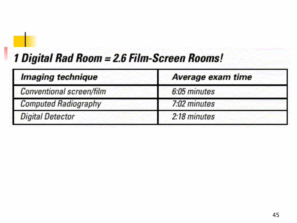
Computed Radiography
and Digital Radiography

2
filmless’ radiology departments
Diagnostic radiographers
have traded their ______ and _________
for a __________ and __________
advance for Rad Sci Prof, 8/9/99

3
What Is Digital Imaging?
Digital imaging is the acquisition of images to a computer rather than directly to film.
4
New Technology Has impacted everyone:
1. Practicing radiologic technologist
2. Educators
3. Administrators
4. Students in the radiologic sciences.

5
Computed Radiography
Fundamentals of
Computerized Radiography

6
Radiology 1895 Radiology 2001

7
CR SYSTEM COMPONENTS
1. CASSETTES (phosphor plates)
2. ID STATION
3. IMAGE PREVIEW (QC) STATION
4. DIGITIZER
5. VIEWING STATION

8
9
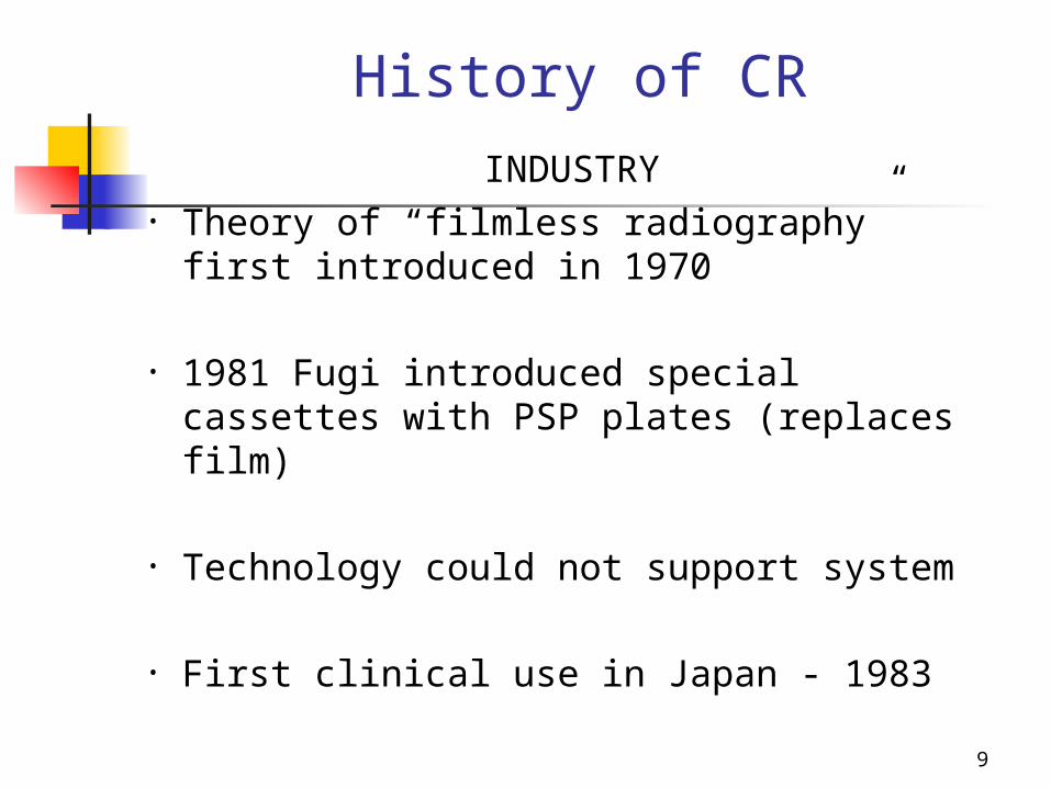
History of CR
INDUSTRY • Theory of “filmless radiography” first
introduced in 1970
• 1981 Fugi introduced special cassettes with PSP plates (replaces film)
• Technology could not support system
• First clinical use in Japan - 1983

10
Predictions 1980 – Bell Labs believed that Unix would
be the worlds dominant operating system
1982 – Bill Gates thought 640K of main memory would suffice for workplace operating systems ( This presentation is 80,000 kb)
1984 – IBM predicted that personal computers would not amount to anything

11
History of CR By 1998 – over 5,000 CR systems in use
nationwide
1998 – Local area hospitals begin to incorporate CR systems in their departments
(Riverside Co. Hosp builds new hospital in Moreno Valley) – completely CR system – 1st generation equipment

12
TERMINOLOGY
1. F/S - ______________________
2. CR - _____________________
3. DR - _____________________
4. DDR - _____________________

13
IMAGE CREATION SAME RADIOGRAPHY EQUIPMENT
USED
THE DIFFERENCE IS HOW IT IS 1. ___________2. ___________3. ___________4. ___________

14

15
Conventional vs. Digital Imaging
Conventional X-ray imaging systems Produce an analog image
(radiographs, & fluoroscopy). Using x-ray tube with films &
cassettes
16
Conventional vs. Digital Imaging
Digital radiography systems require that the electronic signal be converted to a digital signal –
Using x-ray tube – CR cassettes with phosphor plate (PSP) DR systems with transistors (TFT)

17
COMPUTED RADIOGRAPHY & DIRECT RADIOGRAPHY
& FILM SCREENIMAGE CAPTURE
FS - Film inside of cassette
CR – Photostimuable Phosphor Plate (PSP)
DR(DDR) - Thin Film Transitor (TFT)

18
Cassette with film CR with PSP

19

20
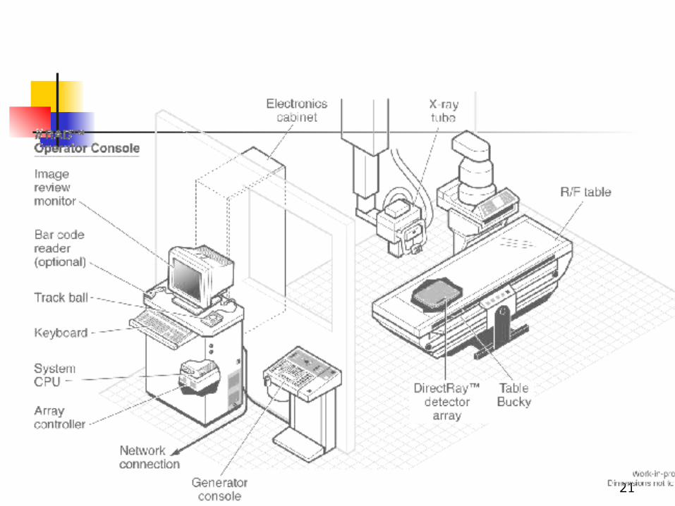
Directed Digital Radiography
(DDR)
Directed digital radiography, a term used to describe total electronic imaging capturing.
Eliminates the need for an
image plate altogether.
21

22
Amorphous Selenium detector technology for DR Direct Radiography

23

24

25
IMAGE CAPTURE
1. _____________ PSP – photostimulable phosphor plate Replaces film in the cassette
2. _____________ – No cassette- Photons captured directly onto TFT Sent directly to a monitor

26
CR vs. FS CR PSP in cassette Digital image Scanned & read- CR
reader
COMPUTER Image stored on
computer Viewed on a
Monitor Hard copy (film)
can be made with laser printer
FILM Film in cassette loaded in a
darkroom Processed in a
processor
FILM Hard copy image –
stores the image Viewboxes – view
the images
27
CR BASICS• Eliminates the need for film as a
recording, storage & viewing medium.
• PSP Plate – receiver
• Archive Manager – storage
• Monitor - Viewing

28
General Overview CR
PSP cassette exposed by conventional X-ray equipment.
Latent image generated as a matrix of trapped electrons in the plate.

29
CR – PSP plate
1. Photostimulable phosphor (PSP) plate
2. Captures photons
3. Stored in traps on plate (latent image)
4. PLATE scanned in CR READER

30
CR Phosphor PlatesCR Phosphor Plates
ABSORPTION EMISSION
X-RAY
LIGHT
LASER STIMULATION
ELECTRONTRAP
ELECTRONTRAP

31
CR – PSP plate
1. Stimulated by a ________________ LIGHT
2. Energy is ________ in a form of _____ light
3. LIGHT captured by photomultiplier tube (PMT)
4. Changed to a __________________ signal

32
How CR works1. Blue released light is captured by a
PMT (photo multiplier tube)
2. This light is sent as a digital signal to the computer
3. The intensity _________ of the light – correlates to the ______ on the image

33
PMT
Beam deflector
LaserSource
Light channeling guide
Plate translation: Sub-scan direction
Laser beam: Scan direction
Output Signal
Reference detec tor
Beam splitter
Cylindrical m irrorf-thetalens
Amplifier
ADC
To imageprocessor

34
X-rayX-raysystemsystem
PatientPatient
PSPPSPdetector detector
ComputedComputedRadiographRadiograph
1. X-ray Exposure1. X-ray Exposure
ImageImageReaderReader
2.2.
ImageImageScalingScaling
3.3.
ImageImageRecorderRecorder
4.4.
une xposedune xposed
exposedexposed
5.5.
re-usablere-usablephosphorphosphor
plateplate

35

36
CR “PROCESSORS”

37
Densities of the IMAGE
1. The light is proportional to amount of light received
2. Digital values are then equivalent (not exactly the same) to a value of optical density (OD) from a film, at that location of the image

38

39
40
ERASING PLATE
1. After image is recorded
2. Plate is erased with high intensity _______________________ light
3. Cassettes are reused
41
CR VS. DR
CR -______________ where the image is first captured on plate and stored = then converted to digital signal
DDR -____________ where the image is acquired immediately as a matrix of pixels – sent to a monitor

42
Digital
Radiography
DirectCapture
IndirectCapture
Direct-to-DigitalRadiography
(DDR)
ComputedRadiography
(CR)
43
DIRECT RADIOGRAPHY Uses a transistor receiver (like bucky)
Captures and converts x-ray energy directly into digital signal
Images seen immediately on monitor
Sent to PACS/ printer/ other workstations FOR VIEWING

44
CR vs DRCR Imaging plate
Processed in a Digital Reader
Signal sent to computer
Viewed on a monitor
DR Transistor receiver
(like bucky)
Directly into digital signal
Seen immediately on monitor
45

46
Image Resolution – (how sharply is the image seen)
CR • 4000 x 4000
• Image only as good a monitor*
• 525 vs 1000 line
• More pixels = more memory needed to store
• CR 2 -5 lp/mm• RAD 3-6 lp/mm• DR ?
• IMAGE APPEARS SHARPER BECAUSE CONTRAST CAN BE ADJUSTED BY THE COMPUTER –
• (DIFFERENCES IN DENSITY)

47
ADVANTAGE OF CR/DR Can optimize image quality
Can manipulate digital data
Improves visualization of anatomy and pathology
AFTER EXPOSURE TO PATIENT

48
ADVANTAGE OF CR/DR
Changes made to image after the exposure
Can eliminate the need to repeat the exposure

49
ADVANTAGE OF CR/DR vs FS1. Rapid storage
2. Retrieval of images NO LOST FILMS!
3. PAC (storage management)
4. Teleradiology - long distance transmission of image information
5. Economic advantage - at least in the long run?

50
CR/DR VS FILM/SCREEN
1. FILM these can not be modified once processed
2. If copied – lose quality
3. DR/CR – print from file – no loss of quality

51
“No fault” TECHNIQUES
F/S: RT must choose technical factors (mAs & kvp) to optimally visualize anatomic
detail
CR: the selection of processing algorithms and anatomical regions controls how the acquired latent image is presented for display
HOW THE IMAGE LOOKS CAN BE ALTERED BY THE COMPUTER – EVEN WHEN “BAD” TECHNIQUES ARE SET

52
DR
1. Initial expense high
2. Very low dose to pt –
3. Image quality of 100s using a 400s technique
4. Therefore ¼ the dose needed to make the image

53
Storage /ArchivingFILM/SCREEN
1. Films: bulky
2. Deteriorates over time
3. Requires large storage & expense
4. Environmental concerns
CR & DR
1. 8000 images stored on CD-R
2. Jukebox CD storage
3. No deterioration of images
4. Easy access

54

55
Transmission of Images1. ___________ - Picture Archiving &
Communications System
2. ____________- Digital Images & Communication in Medicine
3. __________ -Remote Transmission of Images

56

57
Benefits of Computer (web)-based Viewing Systems
1. Hardcopy studies are no longer misplaced or lost- eliminates films
2. Multiple physicians may access same patient films
3. Patients do not have to wait in Radiology for films once study is completed

58
“Film-less” components
1. CR or DR2. CD-ROM or similar
output3. Email capability4. Digitizing capability or
service

59
PACS
Internet VPN
Digital Images Archive
Databaseand Workflow Engine
Workstations
Remote Workstations
Remote Facilities

60
Histogram Analysis
1. A histogram is a plot of gray scale value
2. vs. the frequency of occurrence
3. (# pixels) of the gray value in the image

61

62
HISTOGRAM – a bar graph depicting the density distribution (in numerical values) of the imaging plate
ALGORITHM – a set of mathematical values used to solve a problem or find an average

63
0 200 400 600 800 1,0000
2,000
4,000
6,000
8,000
10,000
12,000
Digital number
Fre
qu
ency
High attenuation(e.g., mediastinum)
Low attenuation(e.g., lungs)
Histogram
Adapted from AAPM TG10

64

65
Statistical plots of the
frequency of occurrence of
each pixel's value

66
Basics of Digital Images
Digital images are a (matrix) of pixel (picture element) values

67

68
The algorithm attempts to distinguish among the parts of the histogram which represent the range of densities from bone to soft tissue

69
Histograms set for specific exams (body parts)
Should produce digital images that are consistent (regardless of kVp or mAs used)
Correct Algorithm (body part) must be selected prior to processing imaging plate

70

71
Methods to Digitize an Image
1. _________ - Teleradiography system (PACS, DICOM)
2. ________ (vidicon or plumbicon)
3. _____________ _______________
4. _____________ _______________

72
FILM DIGITIZER

73
Analog vs Digital1. ______________ -
one value blends into another
1. like a thermometer
2. ______________ - distinct separation
1. 98.6 2. exact
0
20
40
60
80
100
1st
Qtr
3rd
Qtr
East
West
North
74
ANALOG TO DIGITAL IMAGE
1. Conversion of conventional analog films
2. To digital format for PACs and teleradiology applications
3. With scanning laser digitizers

75
CONTRAST & DENSITY1. Most digital systems are capable of
1024 shades of gray – but the human eye can see only about 30
shades of gray
2. The Optical Density and Contrast can be adjusted after the exposure by the Radiographer.
3. This is POST - PROCESSING

76High displayed contrast – narrow window width

77Low displayed contrast (stretched) – wide window width
78
Basics of Digital Images1. Pixel values can be any bit depth
(values from 0 to 1023)
2. Image contrast can be manipulated to stretched or contracted to alter the displayed contrast.
3. Typically use “window width” and “window level” to alter displayed contrast

79

80

81
55 15 30
100 200 500
80 KVP

82
Then the COMPUTER corrects any exposure errors
Therefore almost ANY technique can be used on the patient –
The computer will fix it

83
DOSE IMPLICATIONS
1. More exposure to the patient2. Techniques established
3. Higher kVp = Less mAs 4. Less patient dose
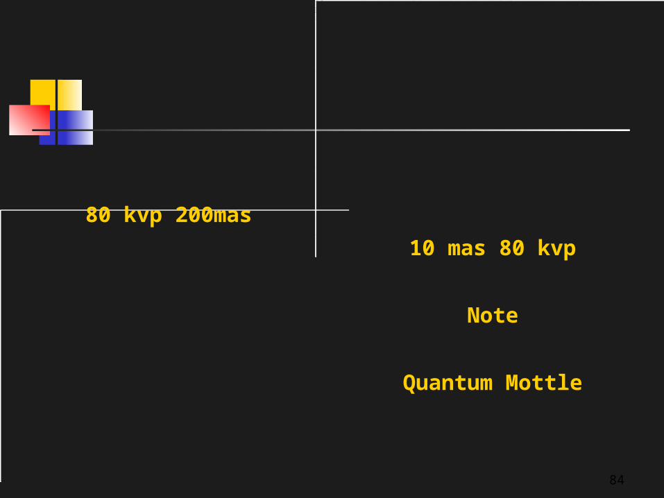
84
80 kvp 200mas
10 mas 80 kvp
Note
Quantum Mottle

85
Dose Implications
1. Images nearly always look better at higher exposures.
2. Huge dynamic range means nearly impossible to overexpose.

86
POST PROCESSING

87
TECHNIQUE CONISDERATIONS
1. KVP Dependant
2. Now COMPUTER controls CONTRAST
3. Higher kVp to stimulate electron traps
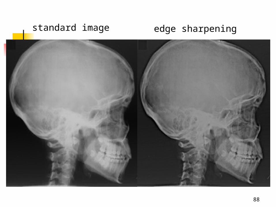
88
standard image edge sharpening

89
NO GRID HAND ALGO
REPROCESSED

90
QC – Reader (replaces Darkroom & Processor & Chemicals
Diagnostic Viewer(replaces film, storage & viewboxes)

91

92
FILM SCREEN PROCESSOR
93
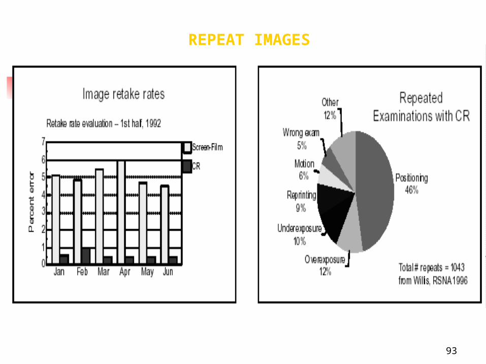
REPEAT IMAGES

94

95
EMERGING PROBLEMS
1. Better – not necessarily faster
2. Learning curve for technologists and physicians
3. Student applications and issues
4. Pitfalls of CR

96
97
1. _____ and proper __________ are critical to good imaging outcomes
2. Just like Phototiming, it can magnify your mistakes
98
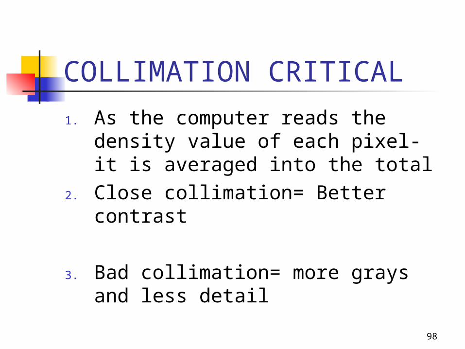
COLLIMATION CRITICAL
1. As the computer reads the density value of each pixel- it is averaged into the total
2. Close collimation= Better contrast
3. Bad collimation= more grays and less detail

99
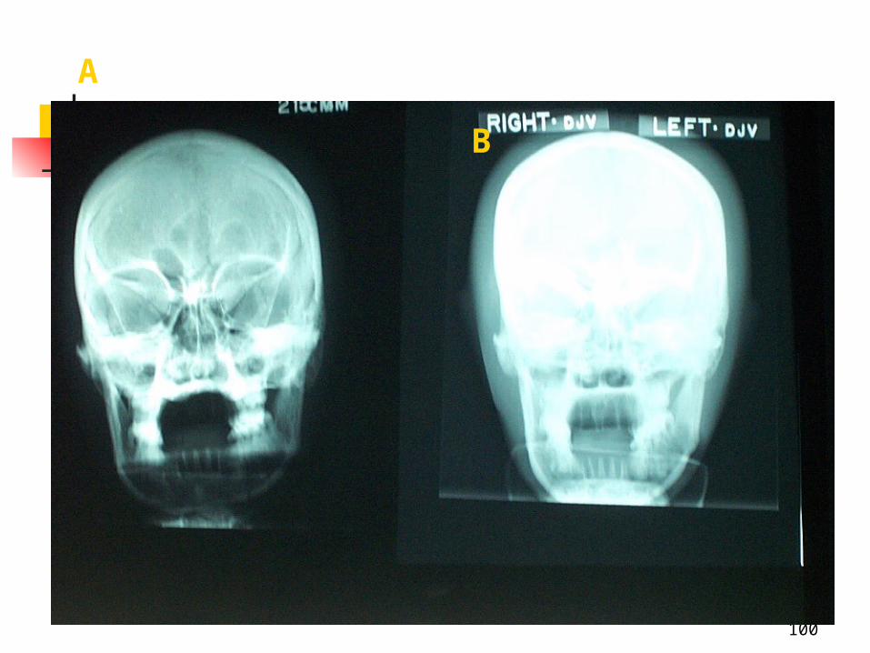
100
A B

101

102

103

104

105
1. Digital imaging is not the end all, cure all for imaging problems
2. It is still technologist dependent

106
To Produce Quality ImagesFor Conventional Projection
or CR Radiography: The same rules, theories, and laws still
apply and can not be overlooked FFD/OFD (SID/SOD) Inverse Square Law Beam Alignment Tube-Part-Film Alignment Collimation Grids
Exposure Factors: KVP, MaS
Patient Positioning

107

108

109
CONVENTIONAL RADIOGRAPHYVIEWING OF “X-RAY FILM” IMAGES

110
NEW IMAGE• Towel that was used to help in positioning a child
• CR is MORE sensitive to
• ARTIFACTS

111
CR image – NEW IMAGE
Line caused from dirt collected in a CR Reader

112
High resolution with digital imaging