filmless radiology: the design, integration
TRANSCRIPT

TIC FILE COPY "9W0AD 4MTR-90W00040
Filmless Radiology: The Design,Integration, Implementation, and Evaluation
of a Digital Imaging Network
Annual and Final Report
NJohn R. CervaBarbara D. Kerlin, Ph.D.
N4 Leon S. Pocinki, Sc.D.
June 1990
DOD DISTRIBUTION STATEMENTApproved for public release; distribution unlimited.
The findings in this report are not to be construed asan official Department of the Army position unless so
designated by other authorized documents.
Supported byD T ICU.S. Army Medical Research and Development Comaand ELECTE
Fort Detrick, Frederick, Maryland 21701-5012 JUL 13 10Contract No. DAMD17-86-C-6145 D
The MITRE Corporation7525 Colshire Drive
McLean, Virginia 22102-3481
I . . . . . .
SECURITY CLASSIFICATION OF THIS PAGEForm ApprovedREPORT DOCUMENTATION PAGE OMBNo 070-18e
la REPORT SECURITY CLASSIFICATION lb RESTRiCTIVE MARKINGS
Unclassified2a SECURITY CLASSIFICATION AUTHORITY 3 DISTRIBUTION /AVAILABILITY OF REPORT .
b DApproved for public release;'2b DECLASSIFICATION DOWNGRADING' CXEDULE distribution unlimited
4 P[RFORMNG ORGANIZATION REPORT NUMBER(S) 5 MONITORING ORGANIZATION REPORT NUMBER(S)
MTR-90W00040
6a NAME OF PERFORMING ORGANIZATION 6b OFFICE SYM3OL 7a NAME OF MONITORING ORGANIZATION
The MITRE Corporation (If applicable)
6c. ADDRESS (City. State. and ZIP'Code) 7b ADDRESS (Ciy, State, and ZIP Code)
7525 Colshire DriveMcLean, Virginia 22102-3481
8a NAME OF FUNDING SPONSORiNG Bb OFFICE SYMBOL 9 PROCUREMENT INSTRUMENT IDENTIFICATION NUMBERORGANIZATION U.S. Army Medical (if applicable)
Research & Development Command Contract No. DA0D17-86-C-6145
b- ADDRESS (City, State, and ZIP Code) 10 SOURCE OF FUNDING NUMBERSPROGRAM PROJECT TASK WORK UNIT
Frt Detrick ELEMENT NO NO 354- NO ACCESSION NO
Frederick, Maryland 21701-5012 63732A I 63732D836 I AV 1 1271' TI'LE (,nclude Securn'y Cl~ssf~cc.raon) ..
Filmless Radiology: The Design, Integration, Implementation,
and Evaluation of a Digital Imaging Network
12 PERSONAL AUTHOR(S)Barbara D. Kerlin, Ph.D.; John R. Cerva; Leon S. Pocinki, Sc.D.
13a TYPE OF REPORT 13b TIME COVERED 14 DATE OF REPORT (Yfar. MonthDoy) 15 PAGE COUNT
Annual *and Final FROM 3//86 TO.3.,J90 1 1990 February 8516 SUPPLEMENTARY NOTATION
Annual covers research for the period of time March 1, 1988 - January 31, 1990.
17 COSATI CODES 18 SUBJECT TERMS (Continue on reverse if neces ary and identify by block number)
FIELD GROUP SUB-GROUP RA II; Radiclogical information management; Digital data
06 02 comunications; Digital images; Filmless radiology; Picture06 05 .. L...LL..........JArhivinz 6 Communication Svst=m,(PACS)- Medical imacn _
19 ABSTRACT (Continue on ,vverm , necessry awn 4entify by block number)j Medical images generated by radiological procedures typically result in the generation
of film-based images. In 1986, the U.S. Army Medical Research and Development Command con-tracted with the )ITRE Corpcratior. to investigate the use of filmless radiology in both itsfixed facility and battlefield medical systems. To support this evaluation, commerciallyavailable Digital Imaging Network System (DINS) equipment was competitively procured andinstalled at two university medical centers, which competed for the opportunity to partici-pate in this evaluation. Equipment provided by AT&T was installed at Georgetown Universityand equipment provided by Philips Medical Systems was installed at the University ofWashington. In parallel, a prototype battlefield DINS was developed by MITRE, using commer-cially available workstation technology, to support concept exploration of DINS in thebattlefield environmen . This document summarizes and presents the results of the systemsengineering studies and technical evaluations that were conducted as part of this four-yearstudy. K.
20 DiSTRIBUTION/IVAILABILITY OF ABSTRACT 21 ABSTRACT SECURITY CLASSIFICATION0 UNCLASSIFIED/UNLIMITED 0 SAME AS RPT 0 DTIC USERS Unclassified
22a NAME OF RESPONSIBLE INDIVIDUAL 22b TELEPHONE (Include Area Cot*) 22c OFFICE SYMBOLMrs. Virginia 'h. Miller 301/663-7325 SGRD-RMI-S
DD Form 1473, JUN 86 Prevous editions are obsolete SECURITY CLASSIFICATION OF THIS PAGE

FOREWORD
For the protection of human subjects, the investigator(s) have adhered to policies of applicableFederal Law 45CFR56.
Citations of commercial organizations and trade names in this report do not constitute anofficial Departmeni of the Army endorsement or approval of the products or services of theseorganizations.
iv

ACKNOWLEDGEMENTS
The authors wish to thank the individuals whose time and efforts led to the successfulcompletion of the DINS project. Principal contributors from MITRE and the participatingorganizations were:
MITRE
Lawrence D. Nadel, PILD.
* John D. Cappelletti * Barbara J. Jacobs" Marcus E. Glenn * William P. Johnson, Ph.D." James R. Gouge, Jr. e David A. Lafko
GEORGETOWN UNIVERSITY
Larry P. Elliott, M.D.Seong K. Mun, Ph.D.Steven C. Horii, M.D.
" Seung-Ok Ahn * Brian Garra, M.D.• Harold R. Benson * John W. Keyes, M.D.* Cate Bozarth, R T. e Kenneth Levin, M.D." Robert Braudes o Betty A. Levine" Mark Carvlin, Ph.D. o Shih-Chung B. Lo, Ph.D." William J. Davros, Ph.D. o Bruce P. Majors" \natoly Dritschilo, M.D. * Marian Meissner" Vadj Dubiansky, R.T. o Edward Milges" Frederick H. Fahey, D.Sc. c Gabriel S. Piumlee* Robert Fielding 9 Eric Rodenhauser* Mathew Freedman, M.D. * Victor Sank, Ph.D.
GEORGE WASHINGTON UNIVERSITY
Robert Allman, M.D.
" Eilene Bradley, Ph.D. * John Schnizlein, Ph.D." Jerry Gaskill o John Sibert, Ph.D.* Murray Loew, Ph.D. o Y.Q. Zhang
v

UNIVERSITY OF WASHINGTON
John Loop, M.D.Albert A. Moss, M.D., FACR
* Jacquie Carter * Stephen I. Marglin, M.D." Marty Caudill s Karl Mills* Hwan Soo Choi e Russell Myers* Larry DeSoto * Ramesh Panwaro Albert Drui, Ph.D. * Hyunwook Park, Ph.D.* Ben Fahey * Judith A. Ramey, Ph.D.o Tracy Florant, M.D. * Alan Rowberg, M.D." Jim Gee e Allan 0. Saarinen, Ph.D.o Mitch Goodsitt, Ph.D. a Udo Schmiedl, M.D., Ph.D." David Haynor, M.D., Ph.D. e Vandan Trivedi, Ph.D.* Linda Johnson * Dean Verheiden* Yongmin Kim, Ph.D. * Chi-Shung Wang" Woobin Lee * Suzanne Weghorst* Thomas Lewellen, Ph.D. e Michelle Wheeler" Gayle Youngs
Finally, the authors wish to acknowledge the efforts of Joseph N. Gitlin, D.P.H., who wasinstrumental in initiating the DINS project, COL Thomas Sweeney (retired) who supported theproject in its early days, and LTC Fred Goeringer who guided the project through its operationalphases
Accession For
jNTIS GCA&JIC TA
U"U
1 .t; .t ,t I,,n/
Av' k,,,bI.t,, Codos - C
-- r I /vi
vi

TABLE OF CONTENTS
SECTION PAGE
Introduction 1-1
1.1 Projczt Background and History 1-11.1.1 Significant Project Accomplishments 1-1
1.2 Project Structure 1-31.2.1 Project Management 1-31.2.2 Project Guidance 1-5
1.3 Objectives and Approach 1-51.4 Audience 1-51.5 Scope 1-61.6 Document Organization 1-6
2 Fixed-Site DINS Implementation 2-1
2.1 Description of the Test Site Hospitals 2-12.1.1 Site Characterization 2-12.1.2 The University of Washington Medical Center (UWMC)
Radiology Department 2-12.1.2.1 Managing Patient Information 2-12.1.2.2 Radiology Procedures 2-42.1.2.3 Support Procedures 2-52.1.2.4 Radiology Records 2-5
2.1.3 GUH Radiology Department 2-72.1.3.1 Managing Patient Information 2-72.1.3.2 Transcription Workload 2-72.1.3.3 Radiology Procedures 2-92.1.3.4 Support Procedures 2-92.1.3.5 Film Library 2-102.1.3.6 Use of the Film Library 2-10
2.2 The DINS Installation at the Test Sites 2-112.2.1 Georgetown University Installation 2-112.2.2 University of Washington Installation 2-15
2.3 Evaluation of Test Site Installations 2-15
vii

SECTION PAGE
3 Selected Technical Investigations at the University Sites 3-1
3.1 Network Simulation 3-13.1.' University of Washington Network Simulation 3-1
3.1.1.1 Results 3-13.1.1.2 Conclusions 3-1
3.1.2 Georgetown University Network Simulation 3-23.2 RIS Interface Issues 3-2
3.2.1 RIS Interface at University of Washington 3-23.2.2 HIS Interface at Georgetown University 3-33.2.3 MITRE Evaluation of DINS/CHCS Interface 3-4
3.3 Workstation Evaluation 3-43.3.1 Clinical Workstation Evaluation at
University of Washington 3-43.3.2 Research Workstation Evaluation at
University of Washington 3-53.3.3 Workstation Evaluation at Georgetown University 3-6
3.4 Computed Radiography Evaluation 3-63.4.1 Evaluations at the University of Washington 3-6
3.4.1.1 Equipment Description 3-63.4.1.2 Results of the PCR Evaluation 3-8
3.4.2 MITRE Filmless Radiology Evaluation 3-83.4.2.1 Conclusions Concerning Clinical Acceptability 3-83.4.2.2 Conclusions Concerning Image Quality 3-93.4.2.3 Conclusions Concerning Ruggedization 3-93.4.2.4 Conclusions Concerning Teleradiology
Capabilities 3-93.4.2.5 Conclusions Concen-ng Costs and Benefits 3-9
3.4.3 Evaluation of Film Digitization at Georgetown 3-103.5 Teleradiology Experiences 3-10
3.5.1 Georgetown University Teleradiology Experience 3-113.5.2 University of Washington Teleradiology Experience 3-11
3.6 Video Image Acquisition Studies 3-133.6.1 Video Image Acquisition Studies at
the University of Washington 3-133.6.1.1 Evaluation Methodology 3-133.6.1.2 Results 3-13
3.6.2 Video Image Acquisition Studies at Georgetown University 3-14
viii

SECTION PAGE
4 Bardefield DINS 4-1
4.1 The Combat Medical Environment 4-14.2 System Requirements 4-14.3 System Definition 4-3
4.3.1 Hardware Configuration 4-34.3.2 System Software 4-5
4.4 Operational Overview 4-54.4.1 Patient Registration 4-54.4.2 Acquisition of New Images 4-54.4.3 Storing and Archiving Data 4-64.4.4 Data Transport 4-64.4.5 System Vulnerability 4-6
4.5 Evaluations of the Battlefield DINS 4-64.5.1 Laboratory Evaluation by MITRE Staff 4-74.5.2 Laboratory Evaluation by U.S. Army and University
Personnel 4-74.5.3 Field Evaluation at the Camp Bullis Training Facility 4-74.5.4 Summary 4-8
4.6 Significance of the Battlefield DINS Prototype 4-84.7 System Simulation 4-8
4.7.1 Model Description 4-94.7.2 Results of the Simulation 4-11
5 Conclusions and Recommendations 5-1
5.1 Conclusions 5-15.1.1 Clinical Acceptability of Fixed Facility DINS 5-15.1.2 Technical Acceptability of Fixed Facility DINS 5-25.1.3 Needed Improvement in Fixed Facility DINS 5-25.1.4 Conclusions Regarding DINS in the Battlefield 5-3
5.2 Recommendations 5-45.2.1 Recommendations Regarding Fixed Facility DINS 5-45.2.2 Recommendations Regarding DINS in the Battlefield 5-6
5.3 General Project Conclusions 5-65.4 General Project Recommendations 5-7
Appendix A: Project Bibliography A-1
Glossary GL-1
ix

LIST OF FIGURES
FIGURE PAGE
1-1 Project Timeline/Key Milestones 1-2
1-2 DINS Project Structure 1-4
2-1 Georgetown University Digital Imaging Network System 2-13
2-2 University of Washington Digital Imaging Network System 2-16
3-1 UWMC PCR Configuration 3-7
4-1 Hardware Configuration of the Battlefield DINS Prototype 4-4
4-2 Casualty Flow through the Five Echelons of Combat Care 4-10
x

LIST OF TABLES
TABLE PAGE
2-1 Size and Other Characteristics of the Test Site Hospitals 2-2
2-2 Annual Number of Medical Image Procedures 2-3
2-3 Average Time for Film Processing Activities at UWMC (Minutes) 2-6
2-4 Activities of UWMC Fileroom Personnel 2-8
2-5 Survey of GUH Medical Image Film Library Users 2-12
4-1 Characteristics of the Combat Medical Care System 4-2
4-2 Peak Image Storage Requirements in an EVAC Hospital 4-12
4-3 Images Transferred to Echelons 4 and 5 4-12
4-4 Comparison of Peak Storage Requirements for X-Rays Onlyand for X-Rays plus CTs 4-13
4-5 Comparisons of Images Transferred to Echelons 4 and 5 forX-Rays Only and for X-Rays Plus CTs 4-13
xi

EXECUTIVE SUMMARY
BACKGROUND AND INTRODUCTION
Under the sponsorship of the U.S. Army Medical Research and Development Command, TheMITRE Corporation installed and evaluated two Digital Imaging Network Systems (DINS) atuniversity medical centers, and examined this technology for use in future Army fixed and battlefieldmedical facilities. To achieve these objectives, MITRE competitively selected GeorgetownUniversity, in conjunction with George Washington University, and the University of Washington toserve as evaluation sites. MITRE also competitively selected AT&T as the vendor for the equipmentinstalled at Georgetown University, and Philips Medical Systems for the equipment installed at theUniversity of Washington. The DINS project began in March 1986 and is scheduled to end in June1990. The objective of DINS is to replace film-based radiological image management with filmlessimage management. In the fllless environment, images are acquired digitally, transferred overcomputer networks, stored on magnetic or optical computer storage media, and displayed on videomonitors.
This report summarizes the detailed evaluations, technical studies, and cost studies that wereconducted under the DINS project. For the most part, it is based on the final reports submitted toMITRE by the two universities. This report seeks to achieve the following objectives:
" To discuss the highlights and major accomplishments of the program in one document.
* To serve as the formal final report on the project to the sponsoring agency.
* To identify other documents that provide detailed information on selected DINS projectactivities.'
OVERALL PROJECT GOALS
From the outset, the scope of the DINS project was broad: to install and evaluate DINS at twouniversity medical centers and to investigate uses of DINS technology in the battlefield medicalenvironment. However, the technologies and issues involved in implementing filmless radiotogy inthe peacetime and combat medical arenas constantly evolve. Considerable effort was directed tomaintaining flexibility within the project regarding current technologies to assure that those beingevaluated were relevant to the Army's future plans. The overall goals of the project were:
Throughout this report, bracketed numbers refer to documents listed in appendix A.
xiii

* To gain experience in planning for and installing DINS within a medical facility
* To gain clinical experience with DINS equipment from an operational perspective.
* To identify features of DINS that either were suitable for use in future systems or requiredmodification before a specification can be written.
* To demonstrate DINS technology to key Army personnel.
* To facilitate technology transfer.
* To apply experiences gained from the fixed facility evaluations to the battlefield medicalenvironment.
SIGNIFICANT PROJECT ACCOMPLISHMENTS
The DINS project can be credited with a number of significant accomplishments with regard tothe use of DINS for medical applications. These include:
" First full-scale use of DINS in a radiology department with links to other parts of thehospital and to remote sites
* First evaluation of filmless radiology in the combat medical environment
" First evaluation at Army medical centers of Computed Radiology (CR) employing phosphorplate technology
" First evaluation of teleradiology as a peripheral to a hospital image management system asdistinguished from stand-alone teleradiology systems
" First demonstration of teleradiology linking overseas U.S. Army bases and ContinentalUnited States (CONUS) facilities
FIXED FACILITY DINS
Baseline data were collected from Georgetown University Hospital [2] and the University ofWashington Medical Center [I] as part of the evaluation as summarized in section 2 of this report.These data characterize the size of the two facilities and the spectrum of services they provided priorto DINS implementation. Table I abstracts general data that characterize the two DINS test sites.These data are useful for comparing the two medical centers and, in the future, for comparisons with
xiv
I

Table ES 1Size and Other Characteristics of the Test Site Hospitals
Test Site
Hospital Sub-Category or MeasureCharmcterlstics UWMC GUMC
Size Number of Beds 450 535
Number of Admissions 13,231 20,202Utilization Average Daily Census 296 414
(Annual Data-1987) Average L.-ngth of Stay (Days) 8 7Number of Outpatient Visits 162,783 127,844Number of Emergency Rm Visits 36,783 24,748
Auending Physicians 391 600Senior Residents and Fellows 530 558
Hospital Ward Practitioners 81 N/AMedical Staff Nurse Coordinators 29 29
Nuys. Specialists 14 38Licensed Practical Nurses 10 17Hospital Assistants 50 N/ANurse Trainees 34 5
Attending Radiologists 10 20Physicist/Radiochemists 9 6
Radiology Fellows 5 8Department Staff Residents 11 13
Technical Staff 35 36Support/Clerical StAff 40 113
N/A: This personnel type not represented at Georgetown University
xv

Defense Department Medical Treatment Facilities. To characterize the radiology departmentworkload, annual totals for medical imaging modalities at the two hospitals appear in table 2.
A number of technical evaluations were conducted at each university using the DINSequipment. These studies, and others, are documented in the University final reports and relatedtechnical publicati,,ns [3][4] [5]. Six key studies are referenced below, along with their majorfindings. They are discussed more fully in section 3.
" Fixed Facility Network Simulation--Bottlenecks were identified that impeded smoothoperation of the system. However, users felt that the system could be made clinicallyacceptable [6] with minor improvements.
* Interface to Other Information Systems--Efforts were made at both evaluation sites tointerface a Radiology Information Systems (RIS) or a Hospital Information Systems (HIS)to the DINS. However, there were limitations in the protocols available for moving data tothe DINS, and data could only move in one direction from the RIS/HIS to the DINS. Forfull integration, two-way communications is considered essential. Requirements forinterfacing future generic DINS tr. other military information systems, such as theComposite Health Care System (CHCS), were also investigated [151[16].
* Workstation Evaluation--Evaluations of the DINS workstations indicated that the displaysmust be faster and that the user interface needs to be more intuitive (i.e., simple andstraightforward for the infrequent user).
" CR Evaluation--CR technology was considered satisfactory by its principal users. It servesas a replacement for film-type images and allows direct capture of digital radiographs byexposing and then scanning a phosphor plate in place of film. Improvements wererecommended regarding user interface and the general system organization.
" I eleradiology--Teleradiology evaluations were conducted at both sites and the technologyappeared to work well when coupled with the DINS.
" Image Acquisition--An evaluation of the system's image acquisition techniques indicatedthat future operational DINS must support interfaces to digital imaging modalities (e.g.,Computed Tomography, Magnetic Resonance Imaging).
Additionally, cost modeling was performed at the University of Washington to estimate costsof future DINS installation and determined cost reductions required to justify future DINSimplementations [20]. It was estimated that a DINS may be considered cost-justifiable if initialsystem costs, using 1988 figures, are reduced by 30 to 50 percent. Trends in the workstation industry,a primary component of a DINS, indicate that such a reduction is probable.
xvi

Table ES 2Annual Number of Medical Image Procedures at Test Site Hospitals
Test SiteModality
Washington Georgetown
General Radiology 50,662 103,64Mammography 2,166 8,574Ultrasound 9,533 7,566Computed Tomography 8,247 12,803Magnetic Resonance 3,861 3,253Angiography 1,020 1,459Nuclear Medicine 2,166 8,641Cardiac Radiology 2,572 2,360
xvii

BATTLEFIELD DINS
As discussed in section 4 of this report, one of the principal goals of the project was to extendthe technology evaluated in the fixed facility environment into the battlefield environment. Toaccomplish this goal, MITRE documented the imaging needs of the Army's deployable combatMedical Treatment Facilities [7.1 and then developed an initial set of functional requirements [9]. Thisled to the design, development, and evaluation by MITRE of a prototype battlefield DINS. Theserequirements include:
* Image Acquisition
- Direct acquisition of digital image data- Electronic capture of inter-facility image data
* Image Display
- Rapid access and display of any image at any DINS workstation- Display of multiple images on a single screen- Adjustability of display by gray scale window width and level- Ability to display image in inverse video- Ability to rotate an image- Ability to flip and mirror displayed image
* Database Administraton
- Registration of new patients- Electronic capture of inter-facility patient data- Storage of all patient data on the local DINS until patient discharge or transfer- Interface to other battlefield medical information systems [14]
* Data Communications
- Intra-facility transport of image data via electronic network or transportable datastorage medium
- Transportability of image data between hospitals or back to CONUS
To assist with the definition of requirements for future battlefield DINS systems, MITREdeveloped a model to simulate the flow of battlefield casualties through the Army combat medicalcare system [10]. The simulation focused on facilities in Echelon 3 of the system, the lowest echelonat which DINS is expected to be introduced. The basic assumptions regarding the flow of patientsand medical images, as well as assumptions introduced for computational simplicity, weredocumented. This simulation showed that a typical peak estimated image storage requirement for an
xviii

Echelon 3 hospital was two Gi,,-bytes, or approximately 1,400 film-type images. A 10 Megabits persecond Ethernet local area network provides sufficient communication capacity for this hospital.
Based upon preliminary analyses, a proto',, battlefield DINS was developed and subjected toevaluations. The results were positive, indicating that this technology is ready for evaluation in thebattlefield environment.
CONCLUSIONS
The conclusions drawn from the evaluations of the fixed facility DINS and the battlefieldDINS prototype are presented in detail in section 5 of this report, and summarized below:
* DINS will not be accepted operationally until interfaces to the modalities are fully digitaland their operation is transparent to the users of both DINS and the imaging modalityhardware.
* A completely functional interface between DINS and HIS/RIS remains a problem and is akey issue for operational acceptance.
* If DINS is to coexist in military medical facilities with CHCS, an interface must be defined
so that
- DINS can be adapted to the CHCS environment.
- CHCS can be modified to interact with DINS.
- DINS can be specified and procured with a proper interface.
* While still expensive, DINS implementation costs may drop significantly, followingworkstation technology cost trends, making an operational DINS more feasible from a costviewpoint.
* Teleradiology is reaching the point where it is both operationally acceptable and costjustifiable.
* Speed of display and ease of operation are critical to user acceptance.
The evaluators at Georgetown University generally found the system to be acceptable, whereasthe evaluators at the University of Washington found the system to be clinically acceptable, withreservations. A number of factors could have influenced this difference in opinion. It should bepointed out, however, that the Georgetown systcm contained two enhancements not included in theUniversity of Washington system. a 'Turbo" display workstation and automatic routing of images
xix

upon acquisition. While the Georgetown system actually experienced an overall lower throughputthan that at the University of Washington, as determined during final system acceptance testing,operations as perceived by the clinical user appeared to occur faster in some cases.
RECOMMENDATIONS
Given the above conclusions, the recommendations made in section 5.2, are summarizedbelow:
" Evaluate DINS in an operational military fixed-facility setting.
" Phase implementation of DINS. Do not attempt to reconfigure an existing radiologydepartment in one operation.
" Use CR as the main source of plain film images for DINS.
" Develop a functional description for a DINS/CHCS interface.
" Continue to develop and evaluate the battlefield DINS prototype, and prepare the technicalspecifications for future battlefield DINS.
xx

SECTION 1
INTRODUCTION
1.1 PROJECT BACKGROUND AND HISTORY
The Digital Imaging Network Systems (DINS) project began in March 1986. The twouniversity evaluation sites, Georgetown University and the University of Washington, were selectedcompetitively and placed under contract to The MITRE Corporation in September 1986. Thevendors, AT&T and Philips Medical Systems, were also selected competitively, based uponspecifications defined in Technical Specifications for a Hospital Based Digital Imaging Network,MITRE Technical Report (MTR-85W242). They signed as subcontractors to MITRE in August1987.
Equipment installation began at Georgetown University in the spring of 1988 while installationat the University of Washington was delayed until the fall of 1988 due to changes in the configurationof the Philips equipment. A complete system was operational at Georgetown University by Jane1989 and at lie University of Washington by Sepiember 1989. While there were delays inimplementing complete systems at each site, component evaluations took place prior to installation ofthe complete system. For example, the Philips Computed Radiology (PCR) system was installed atthe University of Washington by September 1988 and evaluated in subsequent months. Each systemwas subjected to formal acceptance testing to assure proper operation of the system. Evaluationefforts and technical activities were completed by February 1990 and all documentation will becomplete by June 1990. These milestones and other significaLit events during the course of the DINSprojeci at MITRE are depicted in figure 1-1.
1.1.1 Significant Project Accomplishments
The DINS project achieved a number of significant "firsts" with regard to DINS medicalapplications, including the following:
" First full-scale use of DINS in a radiology department with links to other parts of thehospital and to remote sites
" First evaluation of filmiless radiology in the combat medical environment
" First evaluation at Army medical centers of Computed Radiography (CR) using photo-stimulable phosphor plate technology [11]
" First evaluation of teleradiology as a peripheral to a hospital image management system asdistinguished from a stand-alone system
1-1

0 &*r
U. LL
a . l
z0
> e)
CD
Wa.
LoL
CL C
8 zz
0
UU)
U).
8 z0
1--

* First demonstration of teleradiology linking overseas U.S. Army bases and ContinentalUnited States (CONUS) facilities
1.2 PROJECT STRUCTURE
1.2.1 Project Management
The contractual structure of the DINS evaluation project is depicted in figure 1-2. MITRE wasplaced under contract to the U.S. Army Medical Research and Development Command to install andevaluate two DINS at two university medical centers, and to examine this technology for use in futureArmy fixed and mobile combat medical facilities. As described above, Georgetown University, theUniversity of Washington, AT&T, and Philips Medical Systems were selected competitively andwere subcontractors to MITRE under the project.
Project participants had the following general responsibilities:
* MITRE
Assume overall management responsibility for the projectConduct competitive procurements for vendors and evaluation sitesMonitor the subcontractorsMonitor equipment acceptance testsInvestigate applications of DINS technology in combat medical facilitiesDesign, develop, and evaluate a prototype battlefield DINSCoordinate feasibility briefings
" Georgetown University
- Conduct pre-evaluation baseline studies at Georgetown University- Prepare Georgetown University hospital site for equipment installation- D vclop and evaluate an interface between DINS and the University's Hospital
Information System (HIS)- Conduct clinical and technical evaluations of the equipment- Serve as primary DINS demonstration site for military Yrsonnel
" George Washington University
- Provide technical support to Georgetown University
" University of Washington
- Conduct pre-evaluation baseline studies at the University of Washington- Prepare site for equipment installation
1-3

0
~ 0
-7--
00
0 0
4-
Develop and evaluate an interface between DINS and the University's RadiologyInformation System (RIS)Conduct clinical and technical evaluations of the equipmentServe as the "DINS mentor" for Army personnel at Madigan Army Medical Center
" AT&T
- Install DINS equipment at Georgetown University- Maintain equipment during the course of the evaluation project
" Philips Medical Systems
- Install DINS equipment at the University of Washington- Maintain equipment during the course of the evaluation project
1.2.2 Project Guidance
Technical efforts under the DINS project were guided by two documents, the project studyplan [13] and the project management plan [12]. The latter document was issued as a draft in early1987, published as a formal project document in November 1988, and revised in July 1989. Theproject study plan defined the basic goals of the project, including a list of questions to be addressedby studies under the project, and addressed the framework of the studies to be conducted. The projectmanagement plan prioritized the studies defined in the project study plan, assigned primaryresponsibilities for the participating organizations, and identified deliverables resulting from thevarious investigations.
1.3 OBJECTIVES AND APPROACH
The final report of the DINS evaluation project summarizes the technical and evaluative workperformed on the DINS project over its four-year history. It documents the history of the project,outlines key investigation activities, identifies the parties involved in the evaluation, referencesliterature published as a result of the project, and presents conclusions and recommendations resultingfrom the project. Readers are directed to appendix A for a list of documents and conference papersthat address the accomplishments of the project in detail.
1.4 AUDIENCE
This document addresses topics of relevance to the following audiences:
Management and staff of the Army medical command. The report serves both as the finalreport of the DINS project and as a brief summary of the evaluations that occurred under theproject.
1-5

" Personnel in other military and civilian government organizations who anticipate;mplementing DINS at their facilities. Installation and operational experiences at the twouniversity sites, as reported herein, can contribute to the success of future implementations.
* Members of the medical community, generally, and the radiological science community,specifically. This is the professional group that will be most critically affected if the DINSconcept takes hold
1.5 SCOPE
This report summarizes the formal products completed during the four-year life of the DINSconnact. Highlights of the evaluation activities are discussed, and project conclusions andrecommendations are presented. Material presented herein is intended to summarize, not replace, thesource documents, which are referenced in the text and annotated in appendix A, ProjectBibliography.
1.6 DOCUMENT ORGANIZATION
This introduction to the final report provides a brief project overview, including the objectives,approach, and major program milestones. Section 2 describes the systems installed at the two test sitehospitals used for evaluation purposes. It also includes descriptions of the two hospitals, essentially asample of the baseline data provided in more detail in other project deliverables [1][2], to supportfuture comparisons with facilities operated b) the Army. Technical studies addressing a variety ofissues relevant to the fixed facility DINS evaluations are summarized in section 3. The battlefieldsystem is treated in detail in section 4, which also includes a description of, and sample results from,the battlefield medical imaging workload simulation developed at MITRE. Section 5 presents theproject conclusions and recommendations. Appendix A contains detailed project bibliographies forMITRE, the University of Washington, and Georgetown University.
1-6

SECTION 2
FIXED-SITE DINS IMPLEMENTATION
2.1 DESCRIPTION OF THE TEST SITE HOSPITALS
2.1.1 Site Characterization
This section presents data characterizing the two medical centers that participated in the DINSproject as test sites. This information is identified by the term "baseline data," since it describes thetest site hospitals prior to the implementation of DINS. These data serve to establish the size of thetwo facilities and the spectrum of services they provide. This information is intended to serve as apoint of reference from which to view the medical centers' experience in the DINS environment. Themedical center scope-of-service data may also be useful in the future for comparing these twohospitals with Department of Defense (DOD) medical treatment facilities (MTFs).
Table 2-1 presents commonly accepted measures for the physical size, the utilization, and themedical staffing for both hospitals. Table 2-1 also includes detailed medical staffing information forthe hospitals' radiology departments. In each case the staffing data apply only to patient care at themedical center's principal hospital location. The data exclude staff who are largely or exclusivelyconcerned with teaching or research, as contrasted with patient services. The annual totals for thedifferent medical imaging procedures performed at the two hospitals appear in table 2-2.
2.1.2 The University of Washington Medical Center (UWMC) Radiology Department
This section briefly describes the baseline operations (i.e., before DINS implementation) of theRadiology Department of the University of Washington [1].
2.1.2.1 Managing Patient Information
The DECRad Radiology Information Systems (RIS), which supports the daily activities of theUniversity of Washington Radiology Department, consists of modules to perform patient registration,scheduling examinations, patient tracking, film library management, diagnostic reporting,management function and reports.
2-1

Table 2-1Size and Other Characteristics of the Test Site Hospitals
Test SiteHospital Sub-Category or Measure
Characteristics UWMC GUMC
Size Number of Beds 450 535
Number of Admissions 13,231 20,202.0Utilization Average Daily Census 296 414.9
(Annual Data-1987) Average Length of Stay (Days) 8.2 7.5Number of Outpatient Visits 162,783 127,844.0Number of Emergency Rm Visits 36,783 24,748.0
Attending Physicians 391 600.0Senior Residents and Fellows 530 558.0
Hospital Ward Practitioners 81 N/AMedical Staff Nurse Coordinators 29 29.0
Nurse Specialists 14 38.3Licensed Practical Nurses 10 17.8Hospital Assistants 50 N/ANurse Trainees 34 5.0
Attending Radiologists 10 20.0Physicist/Radiochemists 9 6.0
Radiology Fellows 5 8.0Depanment Staff Residents 11 13.0
Technical Staff 35 36.5Support/Clerical Staff 40 113.5
N/A: This personnel type not represented at Georgetown University
2-2
I

Table 2.2Annual Number of Medical Image Procedures
Modality Procedure Test Site
UWMC GUMC
Chest/ribs/stemum/abdnmen 31,538 N.A.Extremities 8,822
General Spine 3,170Radiology Hips/pelvis 2,166
Shoulder 1,532Miscellaneous 3,434
Total for Modality 50,662 103,644
Mammography Total for Modality 2,166 8,574
Obstetrics/gynecology 4,347 N.A.Abdomen 1,592 1157Retroperitoneum 1,144 1569Headneck 667 1401
Ultrasound Pelvis 620 974Extremities 515 --Abdominal 715Chest/breast 276 563Miscellaneous 372 1187
Total for Modality 9533 7,566
Abdomen 2,260 2,843Head 2,235 5,215Chest 1,014 1,211Pelvis 891 1,309
Computed Orbit/Sella 767 431Tomography me 330 439
Maxillofacial 305Neck 272 --Other 173 1355
Total for Modality 8,247 12,803
Brain 1,749 1,247Spine 764 1,425Pelvis 556 65
Magnetic Extremities 290 282Resonance Abdomen 143 169Imaging Miscellaneous 112 38
Chest 108 27Other 139 --
Total for Modality 3,861 3253
Angiography Total for Modality 1,020 1,459
Nuclear Medicine Total for Modality 2,166 8,641
Cardiac Radiology Total for Modality 2,572 2,360
Grand Total 80,227 148,300
N.A.: Data not available.
2-3

The University of Washington Radiology Department generates approximately 232 reports perday; the average length is 420 words and the transcription time averages 6.5 minutes per report.Completing a transcription of a radiologist's report depends on having the three copies (document,file, and doctor's) received in the file room. This system is in the process of being replaced. A digitaldictation/transcription system has been installed. Turnaround time for reports is expected to decrease,while the number of reports is expected to increase.
2.1.2.2 Radiology Procedures
The procedures performed at the University of Washington include the following:
" General Radiology
- Chest Exam. This exam consists of two views and is the most common generalradiology exam.
- General Exam. The procedure for a general exam, ankle or wrist, for example, isessentially the same as for the chest exam.
- Gastrointestinal (GI)/Genitourinary (GU) Exams. These diagnostic radiologyprocedures involve the radiologist in the exam and may make use of a contrastmedium.
" Computed Tomography (CT). A CT study is composed of cross-sectional images ofparticular body parts taken in successive small steps (about 3 mm). Results are stored in athree-dimensional matrix, allowing the image to be viewed from different perspectives.
" Magnetic Resonance Imaging (lvMRI). MRI uses a strong magnetic field to obtain images ofcross-sections of the body. The time to take a series of images is primarily dependent on thepart of the body being scanned.
" Angiography. For this procedure, catheters are inserted into the patient's blood vessels; acontrast medium is injected; and a series of images are obtained using a digitalfluorographic system. There is at least one radiologist-angiographer, one technician, andone nurse present during this procedure.
" Ultrasound. Exam results are recorded on video tape; the ultrasonographer transferssignificant images to hard copy as necessary. When the ultrasonographer has completedhis/her preliminary exam, the radiologist takes one or more scans of the patient.
2-4

2.1.2.3 Support Procedures
The following Radiology Department support procedures, required for the preparation andstorage of medical images, are described briefly:
* Film Processing. One of the critical baseline data elements is the amount of time spentprocessing hard copies of different medical images. Table 2-3 summarizes film processingtime for different image modalities at the University of Washington, based on data that areabout a year old (i.e., 1988) but that match more recent experience.
* Viewing/Searching for Images. Another major concern as the radiology operation movesfrom a hard copy to digital image operation is the change, if any, in the allocation of aradiologist's time. In the current system at the University of Washington, a radiologisttypically spends the following fractions of his/her total viewing time searching for an imagein each of the modalities listed:
- CT/MI: NA
- Ultrasound: 9.5 percent
- Angiography: 2.2 percent
- G/GU: 7.1 percent
- Plain Films: 18.7 percent
- Average, overall: 10.6 percent
2.1.2.4 Radiology Records
The file room is an integral part of the Radiology Department, providing access to a patient'smedical images. The University Hospital keeps all master film jackets, containing all of a patient'smedical images, for eight years from the date of the last entry in the jacket. They are kept in threeseparate areas within the hospital complex:
* Primary storage, located in the Radiology Department, for master jackets that have beenchecked out within the past four months.
" Secondary storage for films that have not been requested duing the last four months buthave been reviewed within the last two years.
2-5

Table 2-3Average Time for Film Procmcing Act; --ties at LJWMC (Minutes)
IActivity*_______ ______
Modality Transport Process Inspect Package Total
CT/MRI 0.22 1.80 1.00 2.86 5.88
Ultrasound 0.34 2.59 0.39 0,75 4.07
Angiography NA 6.02 NA NA 6.02
CI/GU 0.28 1.85 1.45 1.95 5.53
Plain Film 0.23 1.81 096 NA 3.00
All Modalities 0.28 2.22 0.90 1.88 J5.28Transport:~ Transport film to processor.Process: Insert film into processor and remove when processed.
Inspect: Check film to make sure that exam does not need to be repeated.
Package: Collect films and place in folder.
2-6

* Results of pediatric examinations are retained until the patient is 18 years old and eightyears have elapsed since the last date of service.
Table 2-4 summarizes the approximate amount of time the file room personnel spend onactivities in each of the following categories:
" Collating reports
" Updating file jacket information
" Making loans
" Archiving files
" Administration
2.1.3 GUtt Radiology Department
This section briefly describes the baseline operations, (i.e., before DINS implementation), ofthe Radiology Department at GUH [2].
2.1.3.1 Managing Patient Information
The Radiology Department is supported by the Hospital Information System (HIS) whichincludes support for radiology functions. The HIS modules include patient registration, chronologicalindex of patient activity, film jacket tracking system, report generating system, and order entry.
2.1.3.2 Transcription Workload
During a two-week period in 1987, selected for baseline purposes, a total of 3,036 reports weretyped. An average of 217 reports were generated per day, and the length of the average report was111 words. For a sample of 100 reports, the average elapsed time between typing and signing of thereport was 3.2 days. Approximately one-third of the reports were signed within one day.
2-7

Table 2-4Activities of UWMC Fileroom Personnel
AverageTime
Task (Hours/Day)
Collate Records 22.0
Update Jacket Information 17.0
Internal/Alternators 38.0Internal/Radiologists 9.0
Loans Hospital/Clinics 12.0Individual Practitioners 3.0Extemal/Mail 8.0
Monthly Film Move,Archiving Active to Inactive 1.25
Annual Purge 1.4Movement From Inactive toArchives 0.6
Administrative 16.0
2-8

2.1.3.3 Radiology Procedures
The medical imaging procedures performed at the GUH include all of those shown in table 2-2.For purposes of estimating archival requirements and digital image processing workloads, thetabulated data provide estimates of the static load. For baseline purposes, the Georgetown team alsoattempted to examine the data movement, and dynamic traffic loading on the image processingsystem. For this purpose, they focussed on two imaging modalities:
" General Radiology. At the Georgetown University the general radiography service isresponsible for chest, pediatric, and bone radiography studies. The average daily imagegeneration rate is approximately 500 on weekdays and 300 on weekends. The weekdaymaximum image generation rate occurs in mid-morning; the weekend imaging rate exhibitsmaxima in the middle of the morning and at the end of the afternoon.
" Computed Tomography. Georgetown University covers two services, neurological andabdominal imaging, with its two CT scanners. During a two-month data collection period,the monthly average of 682 cases generated 20,000 image frames.
2.1.3.4 Support Procedures
This section describes the general flow of the work in the Radiology Department, introducingand briefly describing the department's support functions. The principal steps in the work flow aredescribed as follows:
" Generating the images. The different divisions of the department maintain the protocols bywhich images are initially generated. Once the images are acquired, they are processed byradiology technologists. Hard copies of the images are taken to the designated filmalternators or directly to the film library.
" Mounting at alternators. Technologists bring the new images to the designated alternators.They are loaded by technologists, film library clerks, or residents. The cases are recorded ina log book kept at the alternator. During a designated period of the day, radiologists reviewthe cases and record an abbreviated diagnosis in the log book and on film inserts. Theimages and film jackets are removed from the alternators and taken to the 24-hour file,described below, by the film library staff during the night shift.
" Generating reports. The reports that have been dictated are transcribed into the RIS; theyare then accessible to physicians in the hospital on the RIS and HIS video terminalsthroughout the hospital. The signed report is printed and sent to the medical record, and tothe referring and admitting physicians.
2-9

2.1.3.5 Film Library
The images are placed in the library for use by the hospital medical staff, transmission to otherhospitals, and other applications. The film library uses two types of envelopes in which to keep thefilms:
" Inserts that contain images organized by category, such as CT, MRI, ultrasound, bone, chest,and others. The inserts are then placed inside a master jacket.
" Master jackets, each of which represents one patient. Radiology Department rules state thata master jacket never leaves the library.
The HIS film library management module keeps track of the inserts but does not trackindividual images.
The Georgetown film library is organized in four levels of storage, defined as:
" The 24-hour file holds the current day's work as it comes back to the file room, and thework done late the previous day.
* The active file maintains the images for the most recent six to nine months.
" The intermediate file holds images up to 24 months. A typical retrieval time for an image inthe intermediate file is approximately two hours.
" The archival storage facility, at a remote site 12 miles from the hospital, keeps images forlonger periods. It typically takes on the order of two days to retrieve an image from thearchives.
For most patients, films are maintained in the film library for a minimum of five years after thelast date of service. For those patients who have had angiography, ultrasound, nuclear medicine,computed tomography, or manunography services, the films are maintained for at least ten years afterthe last date of service. Results of pediatric examinations are retained until the patient is 18 years oldand eight years have elapsed since the last date of service.
2.13.6 Use of the Film Library
Patient images are requested by individual physicians and clinical services. Images arechecked out to the physicians over the counter at the library. This section describes the twocategories of users in turn. The detailed Georgetown University data appearing here, describing theuse of the film image library, the users of the library, and the loans from the library, are based on asurvey of medical image film library users conducted during one summer week in 1987.
2-10

" Individual users. Table 2-5 summarizes several results of the survey. The table shows, forexample, that 60 percent of the users of the film library are either residents or attendingphysicians. The results also show that 77 percent, or approximately three quarters, of thefolders drawn from the library were held out for only one day or less.
" Use by medical services. The Georgetown University study team collected medical imagecheck-out data by reviewing every film request from the hospital's medical services during aone-week test period. Different departments and services request a list of patient jackets forconferences and research purposes. Out of a total of 827 jackets requested during the datacollection week, 534 were found. The remaining 293 jackets were not located for thefollowing reasons:
- 187 were for new patients with no previous studies
- 9 jackets had no films or inserts
- 22 jackets were signed out to someone else
- 75 represented special data problems
The data problems indicated above include ambiguous or incomplete patient information,duplicate names, and duplicate patient identifications (IDs).
2.2 THE DINS INSTALLATION AT THE TEST SITES
2.2.1 Georgetown University Installation
The DINS installation for Georgetown University is depicted in figure 2-1. The basiccomponents of the system and their general technical characteristics are as follows:
" Software configuration--CommView 0 release 3,0. 1, RIS interface (version of 7 December1989), Kermit version 4E.
" Data Management System (DMS)--The DMS serves as the central hub of the DINS. Asdepicted in figure 2-1, the DINS uses a star topology. The DMS supports access by a totalof up to 11 devices via fiber optic links (additional fiber optic links are possible usingmanual switching or a patch panel), and both leased and dial-up telephone lines. The DMSalso supports mirrored magnetic storage of images with a total capacity of 10.4 GBytes.
CommView is a registered trademark of AT&T.
2-11

Table 2-5Survey of GUH Medical Image Film Library Users
Category Variable or Percent ofof Variable Class Interval Category
Resident 39Attending Physician 21
Useis Student 17(427 Responses) Fellow 13
Other 8Patient 2
Personal Review 6Reasons for Consult with Other Radiologists 14Request Other 10
(441 Responses) Clinical Conference 9Take to Another Facility 3
Less than I Day 31Length of I Day 46Possession 1 Week 4
(412 Responses) 2 Weeks 1Other 18
Number of More than 15 Cases 25Requests per 10-15 Cases 18
Week 5-9 Cases 36(153 Responses) Fewer than 5 21
2-12

c _g R
C22
u' C2
0
zz
UC, V
J1j
-13

* Optical Jukebox--The optical jukebox serves as the archival storage system for the DINS. Itcontains 89 twelve inch Write Once. Read Many (WORM) platters, each of which can store2 GBytes of data. The jukebox supports two optical platter disk drive units; however, onlyone drive can be accessed. Each platter can hold approximately 8,000 512 x 512 8 bituncompressed images.
* Results Viewing Stations (RVS)--The RVS is a low-end PC based workstation supporting asingle screen display. This device was used primarily to support non-diagnostic imagedisplay in several hospital wards via Ethemet and at the home of one radiologist via a dial-up telephone link.
" Results Viewing Station Gateway--The RVS gateway provides a one-way image link fromDINS to Ethernet.
" Acquisition Module (AM)--The acquisition modules are used to acquire images from thevarious modalities into the DINS. Video frame grabbers were used to re-digitize imagesfrom CT, MRI and, Ultrasound, and digital images were accepted directly from laser filmdigitizers (and CR, in the case of the University of Washington.) The AMs also support aDR- 11 parallel digital interface, currently used to connect to the laser film digitizers. A newversion of the AM, the 32 bit AM, has been received and will support the ACR-NEMAdigital interfaces for MRI and CT.
" Four-Screen Enhanced Display Workstation (EDW)--The four screen display stationssupports four 1280 x 1024 gray-scale monitors and basic image manipulation capabilities.Local disk storage is available at each of these workstations. The "turbo" package, installedon the workstations in Abdominal Imaging, General Radiology, and Neuroradiology,provides for increased image display speed and expanded local disk storage.
* Two-Screen Enhanced Consultation Workstation (ECW)/AM--The two screen displayssupports both display and acquisition of images.
" Laser Film Digitizer--The laser film digitzer supports acquisition of images into the DINS ofimages that have already been committed to film. The approximate resolution of the laserfilm digitizers used on the DINS project is 2048 x 2048 x 12 bits.
" Research Image Processing Stations--The research image processing stations at GeorgetownUniversity consist of a Pixar Image Computer and an AT&T Pixel machine. These stationsare used for advanced image processing research and investigation of potential workstationdesigns and are able to receive images from DINS via Ethemet.
" HIS/DINS Interface- The HIS interface consists of a desktop computer that communicatedwith the in-house HIS and with the DINS, using the Kermit protocol.
2-14

2.2.2 University of Washington Installation
The DINS installation for the University of Washington is depicted in figure 2-2. The systemconfiguration at the University of Washington was essentially the same as that at Georgetown withthe following exceptions:
" Number and placement of workstations.
" Integration of a Philips Computed Radiography (PCR) system at the University ofWashington. PCR combines conventional radiographic techniques with stimulablephosphor, laser, and computer technology to produce digital X-ray images. The primaryfunction of PCR is to acquire, process, and transmit high-resolution (up to 2510 x 2000 with10 bits per pixel) X-ray images employing reusable stimulable phosphor image plates inplace of conventional film/screen detectors.
" Dedicated 1.544 Mbps T1 leased line communications to the Harborview Medical Center(Seattle, WA), VA Medical Center (Seattle, WA), and Madigan Army Medical Center(Tacoma, WA).
" Use of a long distance teleradiology link to Alaska at the University of Washington.
* The research image processing station at the University of Washington was configureddifferently than at Georgetown, consisting of a Pixar image computer, a MegaScan high-resolution display monitor, and a parallel transfer disk capable of performing high-speedupdates of the MegaScan monitor display.
" The DMS at the University of Washington was configured with 5.4 GBytes of mirroredmagnetic disk storage.
* Interface to a DECrad RIS.
* "Turbo" workstations or image routing capabilities not supported by the University ofWashington DINS.
2.3 EVALUATION OF TEST SITE INSTALLATIONS
Evaluations at the two sites generally proceeded according to plans laid out in the project studyplan and project management plan. The activities fell into two categories:
Technical evaluation--evaluation of various technical aspects of the system includingdisplay image quality, network performance and interfacing issues
2-15

E5
00
522
030
c h~~
9 c -0
& 2 -6
C3 HofU
LL ME o
2-1

* Clinical evaluation--evaluation of the medical professionals' reactions to various aspects ofthe system and its overall effect on clinical practice.
Details regarding these evaluations are discussed in each University's final project report [3][4]and in other papers and publications listed in appendix A. Key conclusions and recommendationsfrom the fixed facility evaluations are included in section 5 of this document. Selected studies andevaluations conducted at the University sites are abstracted in section 3 of this document.
2-17

SECTION 3
SELECTED TECHNICAL INVESTIGATIONS AT THE UNIVERSITY SITES
A number of technical evaluations were conducted at each site using the DINS equipment.This section presents a brief overview of some of the key activities conducted. The University finalreports and conference papers contain more detailed information on these activities.
3.1 NETWORK SIMULATION
3.1.1 University of Washington Network Simulation
In order to better identify bottlenecks in the design of the DINS, the University of Washingtondeveloped a simulation model of the system. As the system installed at the University wasproprietary, it was not possible to modify system software to incorporate automatic collection of datausing check points within the system. Therefore, baseline input for the model was generated byobserving the system's physical response to various stimuli (e.g., request display of an image and waitfor the image to be displayed and observe the indicator lights on the communications module.)
3.1.1.1 Results
The following results were obtained from the University of Washington simulation studies:
* The central database unit, Data Management System (DMS), becomes the global bottleneckwhen more than four modes of the DINS ask for services simultaneously.
* The image acquisition and compression times at the image capture units, and thedecompression time at the display workstations are some of the local bottlenecks.
SThe teleradiology link to Alaska did not seem to degrade system performance during thenetwork modeling exercise. However, the teleradiology link was found to degrade systemperformance in subsequent acceptance testing of the system.
3.1.1.2 Conclusions
Based upon the results obtained from the simulation studies, the University of Washingtonbelieved that the system was not yet ready for clinical use due to slow system response. However, ifthe causes of this slow response were removed and system performance were improved, then thesystem could be considered clinically acceptable [6].
3-1

3.1.2 Georgetown University Network Simulation
Georgetown University carried out modeling of the DINS at a different level from that done atUW. The model was built on operational characteristics, and viewed devices as queueing systems.While real-world values were used to establish operating parameters of the system simulation, it didnot build a detailed communications network model (for example, simulation down to the data packetsize). A number of studies were carried out usinb the queueing model, and were compared withactual systems performance. Both acquisition and display were successfully modeled, and helpedreveal reasoning behind some systems design. An important example is in the acquisition model; itwas shown that the bias the Acquisition Module (AM) software builds in towards minimizing inputqueue length is a valid one, since it will result in a minimum wait time for the technologist acquiringthe images on clinical services. The success of these studies also prompted GUH to use the model ina predictive way. The impact of adding a fourth ultrasound machine on either of the two AMs wasmodeled. In the process, the model helped illustrate how unevenly loaded the AMs were, and theresult was a reconfiguration of the real DINS.
The GUH experience was that the overall operational model could be used to verify systemdesigns and to optimize the configuration of the equipment on the network. While the DINS operatedsatisfactorily a: GUH, the simulations helped point out ways in which modifications could be made soas to minimize tCie impact of additions or changes.
3.2 RIS INTERFACE ISSUES
The DINS at each evaluation site was interfaced to the facility's existing RIS or HIS for thepurpose of dowLoading patient data to the DINS. At each site, the interface was limited to un-directional data transfer from the RIS/HIS to the DINS. More information on this topic can be foundin each Universit)'s final report and assorted conference papers. Additionally, MITRE investigatedthe requirements for interfacing DINS to other military information systems, such as the CompositeHealth Care System (CHCS) [15][16].
3.2.1 RIS Interface at University of Washington
The RIS used by the University of Washington Department of Radiology is the DECradsystem. The interface between DECrad and the DINS was implemented on an desktop computer.The desktop computer was interfaced to the DLNS via a serial interface running the KERMITcommunication protocol. Communication between the desktop computer and DECrad occurred overan 8-port serial communication interface. The DINS accepted the following transactions from theRIS:
3-2

" Add/modify/delete patient
" Merge patients
" Add exam/modify/delete
" Merge exams
" Add/modify/delete report
" Audit
The RIS interface was found to behave unreliably, with the link frequently failing to operate.When operational, the link tended to degrade performance of the DINS. Furthermore, it was felt thatthe DMS did not have the computing power necessary to service the RIS interface while serving theDINS workstations. These problems and their cause are discussed in some detail in the University ofWashington final report. Due to the problems encountered, the University of Washington staffconsidered the operation of the RIS/DINS interface to be unacceptable for clinical usage. Theirrecommendations for improving this situation include:
* The American College of Radiology/National Electrical Manufacturer's Association(ACR/NEMA) RIS/HIS/PACS message format should be used when that format is released(expected in late 1990), and a more efficient communication protocol than Kermit should beconsidered. Improved error handling and error recovery are required.
" The RIS identifier must be used in the DINS as the RIS initiates all cases. A manual meansmust exist for entering this identifier into the DINS if the RIS/DINS interface fails.
" Two-way communication is required so that the DMS can request the initiation of a requiredtransaction.
3.2.2 HIS Interface at Georgetown University
Though the GUH experiences in designing and testing of the HIS/DINS were similar to thoseencountered at UW in terms of the hardware selected and protocol used for communication, themethod used for the interface and the software environment were different. The version of theinterface being used at Georgetown ran for over five months without technical problems and wasclinically useful. Through the capture of the HIS radiology order inf, rmation, the technologists werefreed from having to re-enter the patient demographic information when setting up acquisition at the
3-3

modalities. Some operational issues regarding the interface still need to be addressed by the GUHHIS managers and the DINS vendor, but these would result in additional enhancements to theinterface and are not necessary to enable its basic operation.
The HIS-DINS interface at GUH did not cause any degradation of system performance. Nochange in image capture, transfer, or display time was seen as a result of running the HIS interfaceprotocol. The protocol uses the ACR-NEMA data set structure, which, at present, is the only widelyaccepted standard for this interface. The GUH team recommends using ACR-NEMA structure. It isvery likely that an ACR-NEMA standard that specifically addresses the HIS/RIS/DINS interface issuewill be produced. Such a standard is in development at present, and will follow other standards (e.g.,HL7, IEEE Medix) in this development.
3.2.3 MITRE Evaluation of DINS/CHCS Interface
The requirements for interfacing DINS to CHCS were examined and various possibleimplementation configurations were examined. Configurations varied from logically separate DINSand CHCS with one-way or two-way communication to a logically similar system supporting bothDINS and CHCS functions. The advantages and disadvantages for each approach were evaluated anddocumented. It was recommended that, once DINS prototypes had been evaluated, a functionaldescription should be developed for incorporating the DINS interface into CHCS. This interfacedefinition must then be included in any specifications for future DINS for military environments.
3.3 WORKSTATION EVALUATION
3.3.1 Clinical Workstation Evaluation at University of Washington
The University of Washington conducted an evaluation, using the installed equipment, todetermine optimal requirements for DINS workstations. The evaluation methodology andworkstation specifications are discussed in detail in the University of Washington's final projectreport. The workstation evaluation was conducted primarily by exposing the workstations to expertsin radiology and human-computer interactions and requesting that these individuals answer a detailedevaluation questionnaire. The general conclusions and recommendations coming from this studywere as follows:
The speed of the basic DINS workstation display (8-second image display time) was notsufficient for radiology applications. However, the display time for the research imagingstation (1.5 seconds per image) was considered to be clinically acceptable.
3-4

" The reviewers felt that two screens were needed for a minimal capability display station(e.g., RVS) and that more than four screens were required at the larger diagnosticworkstations.
" The user interface must be more intuitive.
* An intelligent scheme for automatically routing images to appropriate workstations inadvance of a clinical review session is desirable (such ar :uto-routing scheme was installedat Georgetown University late in the evaluation).
3.3.2 Research Workstation Evaluation at University of Washington
The University of Washington implemented a prototype electronic alternator utilizing anadvanced image processing workstation and evaluated its clinical acceptability as a primarydiagnostic workstation. The goals of the study were to utilize the unique features of the workstation(large image memory of 72 MBytes, a high-speed parallel transfer disk, and a 2560 x 2048 high-resolution image monitor) to demonstrate the feasibility of a limited model of the electronic alternatoras a primary diagnostic workstation in the DINS environment, to evaluate its capability in imageviewing and diagnosis, and to assess the feasibility of an icon-based user interface to select andrearrange images on the monitor. The general conclusions from this study were as follows:
" Using currently available hardware, the display speed of the locally stored images was fast
enough to be clinically acceptable to radiologists in making primary diagnosis.
" The icon-based user interface was quite acceptable.
" The spatial resolution (2560 x 2048) and its image quality were acceptable.
" The contrast resolution of only 8 bits per pixel was not adequate for use in an electronicalternator displaying medical images for primary diagnosis.
" The functions provided by the separate text monitor should be integrated into the imagemonitor.
3-5

3.3.3 Workstation Evaluation at Georgetown University
Georgetown University had the opportunity to evaluate the original display workstations(DW), the enhanced graphics DW (EGDW), the "turbo" EGDW, and the single-screen RVS. Clinicaluse of the workstations increased as their speed and capability increased. The DWs were primarilyused for review of cases for comparison; no primary reading was done. The EGDWs were the first(in four screen configuration) to be used for primary interpretation. The neuroradiologists used anEGDW to read some of the MRI cases from the Montgomery Imaging Center.
The major change in use patterns developed when the "turbo" EGDWs were installed. Thisupgrade increased local storage capacity to 1.3 Gigabytes (about 2,100 images of 512 x 512 x 8 bitsize) and made z marked improvement in display speed. From the local disk, the time to fill a screenwith 20 images of 512 x 512 x 8 bits was improved from 24 seconds to 7 seconds. For a full-screendisplay of a digitized film (1684 x 2048 x 12 bits in memory, 960 x 1024 x 8 bits displayed), the timeimprovement was from 8.6 seconds (very close to the UW measured 8 seconds for CR images)reduced to 3.2 seconds. The remote display times were not as dramatically reduced, sincecommunicatior protocol overhead erodes some of the advantage. In spite of this, reductions in therange of 25 - 30 percent were measured.
In addition to the improved speed, new software allowed for automatic routing of examinationsto workstations. This allowed building of real work lists, and prompted the Ultrasound Section tobegin primary reading at the workstation for about 50 percent of its cases.
3.4 COMPUTED RADIOGRAPHY EVALUATION
The University of Washington conducted clinical and technical evaluations of the PCR systeminstalled as part of their DINS (figure 3-1). These evaluations are discussed in detail in the Universityof Washington's final report; however, key points and results of that evaluation are abstracted here.Phosphor plate technology was also evaluated by MITRE at Ft. Meade and Ft. Bragg Army hospitals[11]. Additionally, Georgetown University conducted evaluations of film digitizers.
3.4.1 Evaluations at the University of Washington
3.4.1.1 Equipment Description
The PCR system uses phosphor plate technology to directly acquire radiographic imageswithout first going through the process of generating films. A cassette (with the same physicaldimensions as a standard film cassette) containing the phosphor plate is placed behind the patient as
3-6

0C)
0
IIn
3-7-

would a standard film, and the patient is X-rayed in standard fashion. The phosphor plate cassette isthen placed into a reader that extracts a digital image with a resolution of 1760 x 2140 x 10 bits for a14-inch by 17-inch X-ray format. Images are produced on film via a laser film digitizer and can beretrieved at the image processing station. At optical disk unit provides image storage for the PCR. Aone-way image interface allows transfer of digital images from the PCR to the DINS.
The advantages of CR technology include the following:
* Film and chemicals are not required, thus allowing true filmless radiology.
o Digital images can be enhanced through the use of image processing, primarily, edgeenhancement.
* Image quality can be improved through digital compensation, thus improving overall imagequality and reducing patient X-ray exposure due to retakes of poorly exposed images.
3.4.1.2 Results of the PCR Evaluation
Technicians generally appreciated the image enhancement capabilities, automated managementof images, and elimination of repeat procedures. However, the following recommendations weremade:
" Overall operational complexity must be reduced, including user interface, system responseto user errors, consistency in the user interface and overall system configuration.
" Sufficient training must be provided for new users.
" Easily performed, automated quality control procedures must be implemented and run atregular intervals.
3.4.2 MITRE Filmless Radiology Evaluation
Filmless radiology was also evaluated at two Army medical centers: Womack Army MedicalCenter at Ft. Bragg, North Carolina, and Kimbrough Army Community Hospital at Ft. Meade,Maryland. The results of the two 30-day examinations of the filmless radiology system led totentative but significant conclusions concerning the likely value to the Army of an appropriatelyconfigured filmless system. These conclusions appear below.
3.4.2.1 Conclusions Concerning Clinical Acceptability
The system achieved considerable acceptance from radiologists and radiological technicians atFt. Meade and Ft. Bragg during the evaluation periods. This was true despite the fact that the system
3-8

was viewed as experimental and was not specifically configured to meet the requirements of eithertest hospital. The high potential value of the system in combat casualty care was widelyacknowledged among clinicians at both hospitals.
3.4.2.2 Conclusions Concerning Image Quality
Based on laboratory studies on filmless technology, prior field studies employing filmlesstechnology in general, and the clinical judgment of radiologists using the system during theexamination, the system is capable of very high quality images. In some instances, this quality ishigher than that of film, due to the system's ability to compensate for certain shortcomings in X-raytechnique. In the opinion of all radiologists who used the system, it produces images that areadequate for the majority of cases in peacetime fixed facilities and that exceed image qualityrequirements during combat casualty care.
3.4.2.3 Conclusions Concerning Ruggedization
The system used during the examination was not ruggedized, but in the opinion of experts onthe subject, there are no significant technical barriers to making the system sufficiently rugged to befield-deployable. This conclusion should be verified by testing an appropriately redesigned systemagainst applicable field performance criteria.
3.42.4 Conclusions Concerning Teleradiology Capabilities
The system can be made fully compatible with all requirements for teleradiology links amongfixed facilities. Though untestable during the examination, it seemed likely that the sameperformance could be expected among combat care facilities since the technology underlyingteleradiology is well established.
3.4.2.5 Conclusions Concerning Costs and Benefits
An appropriately configured system has the potential for reducing the cost of radiology. Majorcost reductions can be achieved by eliminating film, film processors, chemicals, and film storage.Important cost savings associated with the time spent by radiologists and technicians handling casescan also be realized. Potential benefits associated with the system can be achieved in the area ofimage acquisition, archiving, display, and inter-departmental and inter-facility communication.
3-9

3A.3 Evaluation of Film Digitization at Georgetown
While the Georgetown CR facility was not included as part of the DINS, film digitization wasinvestigated as a method for introducing plain film images into the system. Two DuPont laser filmdigtizers and a Konica laser film digitizer were used.
Film digitization is used clinically at Georgetown, though engineering studies of the digitizerperformance showed them to be minimally acceptable. Problems were noted with noise, resulting in12- bit data that contained usable information in only the top 8 or 9 bits. Despite these difficulties,the resulting images have been used clinically, but not for primary reading by radiologists.
A far more serious problem with the digitizers has been reliability. Until effective methods ofpreventive maintenance were used (primarily carefully cleaning the digitizer electronics bay), thedigitizers would rarely run for more than 24 hours without having to be reset. Downtime has beensignificantly reduced, but still exceeds that of other devices on the network.
The technologists have been excellent at accepting the use of the digitizers even though it addsa step to their work flow. Operation of the laser digitizers is not difficult, and compliance is nearly100 percent.
Because of the reliability issues, image noise problems, and workload for users, this method ofacquiring plain radiographic images cannot be recommended for general use. For acquisition of a fewimages, or importing images that are only available on film, the technique is acceptable. In the modetested at Georgetown, film digitization will not support input of the entire plain film load of a typicalteaching hospital.
3.5 TELERADIOLOGY EXPERIENCES
Teleradiology was evaluated extensively under efforts previous to the DINS evaluation project.The initial concept of teleradiology was that image acquisition and transmission equipment located atmultiple remote medical clinics would send digital copies of images to a central location for reviewby radiologists. Under DINS, this concept is modified slightly: i.e., remote site teleradiology systemsare now considered peripherals to the DINS system, much as a computer printer is peripheral to adesktop computer, and the central reading site is not merely a reading site for teleradiology imagesbut is an image management system for the hospital and the remote sites. Teleradiology workstationscan be viewed as an extension of the hospital's image management system.
3-10

3.5.1 Georgetown University Teleradiology Experience
Experience with teleradiology was gained at Georgetown primarily through two routes:remote access by the Montgomery Imaging Center (MIC) and by using a workstation from aphysician's home (see figure 2.1). During the course of the DINS project, Georgetown Universityoperated the MIC on an outpatient basis. The Siemens CT and MRI units were interfaced to an AMat the MIC, and images were transmitted 15 miles to Georgetown University via a TI link at 1.544Mbps. The primary use of this link was to facilitate consultation between the staffs at GeorgetownUniversity and the MIC. In 1988, 1030 CT and 1,174 MRI examinations were performed at the MICin consultation with Georgetown University.
The main users of the MIC teleradiology link were the neuroradiologists. They did primaryreading, preliminary reading, and completeness evaluation using the system. The films from casesreviewed on the workstation were reviewed the next day, and over the period of the evaluation, nosignificant problems in interpretation from the workstation were found.
A link to one radiologist's home has been in place since July 1989. It is used for readingultrasound cases when he is on call. He has found that during the average week of on-call coverage,he reads approximately four cases on the system. This translates into avoiding a trip in to the hospitalabout 80 percent of the time. The remainder of the time, the examination is one he must performpersonally. The use has been successful, and plans are underway to install a second unit at anotherradiologist's home. All data communication is over voice-grade telephone lines using an adaptivemodem. If line conditions are good, a 19.2 kilobit per second rate can be achieved. A typical displaytime is 59 seconds to paint a 512 x 512 x 8 bit image as it is being received. This timing is based onusing low (2:1 lossless) compression.
In other tests and demonstrations of teleradiology, images were sent successfully fromGeorgetown to San Antonio, Texas, San Diego, California, Denver, Colorado, and Seoul, Korea.These were all accomplished using voicegrade telephone lines with the same modems used for thelocal teleradiogy links.
3.5.2 University of Washington Teleradiology Experience
Experience with teleradiology at the University of Washington was gained primarily throughteleradiology links with Sitka, Alaska, the Seattle VA Medical Center (VAMC), and HarborviewMedical Center (figure 2.2). The characteristics of these three sites are listed below:
Sitka, Alaska
Equipment: AM, Laser Film Digitizer (LFD)
3-11

- Link: 4800 baud dial-up
- Distance to UW: 800 miles
* VA Medical Center
- Equipment: AM, LFD, interface to CT scanner
- Link: 1.544 Mbps T1
Distance to UW: 10 miles
" Harborview Medical Center
- Equipment: Consultation Workstation
- Link: 1.544 Mbps TI
- Distance to UW: 5 miles
Data were generated by the LFD at a resolution of 1280 x 1024 x 12 bits and reversiblycompressed to a ratio of between 2 and 2.5:1 prior to transmission.
The teleradiology evaluation ran for a period of 21 weeks. Following is a summary of the caseloads transmitted from Alaska and VAMC to the University of Washington:
Alaska Studies VAMC Studies
Chest 60 48Spine 36 27Extremities 61 43Abdomen 20 25Skull 32 11Ultrasound 48 0CT 0 26
TOTALS 257 180
The conclusions of this evaluation were as follows:
* Reliable, high-speed communication is required for the teleradiology links to be consideredacceptable. University of Washington staff generally found the 4800 baud link to beunacceptably slow.
3-12
I ml . . . .

Teleradiology image quality from digitized film was judged to be acceptable for manyapplications, marginal in some (e.g., mastoiditis, infant respiratory distress syndrome), andunacceptable in others (e.g., mammography).
3.6 VIDEO IMAGE ACQUISITION STUDIES
3.6.1 Video Image Acquisition Studies at the University of Washington
The DINS equipment used at both Georgetown University and at the University of Washingtonused frame grabbers to acquire images from modalities that currently generate video output (CT, MR,Ultrasound). The frame grabber functions by capturing the video signal being sent to a displaymonitor by the rodality. This teclnical approach has the advantage of allowing an external system toacquire images from the modality without having to modify the modality, through the addition ofinterface hardware and software, to support a computer network interface. The disadvantage is thatthe frame grabber is re-digitizing a signal that had once been digital and was converted to analog fordisplay on the modality's video monitor. This second signal conversion results in significantdegradation of the resulting image when compared to the original digital image.
3.6.1.1 Evaluation Methodology
To evaluate the frame grabber acquisition scheme, several digital image phantoms weregenerated on the General Electric (GE) CT9800 CT scanner, displayed on the console displaymonitor, and captured by the DINS. Once captured, these images were routed through the DINS andsent to an RVS where they were transferred to floppy diskette and moved to an image analysiscomputer. This procedure was repeated using the GE Signa MRI scanner and Society of MotionPicture Test Engineers (SMPTE) test pattern.
3.6.1.2 Results
Analysis of the images acquired using the DINS frame grabber yielded the following results:
" The resulting images were characterized by approximately two percent interference due to60 cycle hum.
" The captured SMPTE test pattern exhibited blurring of alphanumeric characters.
" The frame grabber did not capture the full gray scale range of the original image. Of theoriginal 12 bits (4096 possible grey levels) available in the original CT image, only 8 bits(256 grey levels) were made available to the frame grabber at the modality's video out, and
3-13
p

only 5 to 6 bits (32 to 64 grey levels) of image information were finally acquired by theframe grabber for use within the DINS. Even if this degradation from 8 to 5 bits did notoccur, the frame grabber approach would not be acceptable in a fully operational DINS. Theradiologist would lose the benefit of having access to the full 12 bits of data for windowwidth and level adjustment, and the Radiology Department would be required to maintaintwo separate digital archives: a tape archive for 12 bit images from the modality in additionto the DINS archive containing the frame grabber images.
Operationally, the frame grabber performed slower than standard optical multiformat camerasand newer laser film printers, which adds some delay to the image acquisition process. Further, sincethere was no digital interface between DINS and the modalities, there is substantial delay required dueto dual entry of patient demographic data into both the DINS and the modalities.
3.6.2 Video Image Acquisition Studies at Georgetown University
The Georgetown timing studies of frame grabbing have shown typical response times undertwo seconds (1.5 seconds/image with version 3.0 software), which is faster than most CRT-basedmultiformat cameras but not faster than loading the image buffer of a laser film printer. Thissomewhat slower speed of frame grabbing is noticed by technologists whose cameras are faster.
Despite the problems of digitized video (and GUH agrees with UW that the artifacts, noise, andothei irregularities are present), ultrasound images have proved to be of sufficient quality to bereadable. In fact, the ultrasound image size, at 512 x 512 x 6 bits (typical), does not "strain" the framegrabber as much as an 800-line CT. For CT and MRI, with their larger dynamic range, digitizedvideo is not sufficient for primary reading. It does suffice for most correlation uses.
3-14

SECTION 4
BATTLEFIELD DINS
The U.S. Army plans to implement medical imaging systems throughout its deployable MTFsin the early 1990s. The filmless environment will require an electronic management system to store,display, and transport the digital images. As part of its work for the U.S. Army Medical Research andDevelopment Command, MITRE developed an understanding of the imaging needs of the Army'scombat medical care system, and addressed these needs in a prototype Battlefield DINS. This sectiondescribes the activities MITRE performed in this part of the DINS project [8].
4.1 THE COMBAT MEDICAL ENVIRONMENT
The five echelons of medical treatment capabilities in which the Army combat medical caresystem is organized are characterized in table 4-1. Mobile Army Surgical Hospitals (MASH),Combat Support Hospitals (CSH), and Evacuation (EVAC) Hospitals typically contain 60, 200, and400 beds, respectively. In one of these MTFs, the medical imaging capability is housed in a centrally-located International Standards Organization (ISO) shelter. Each X-ray module contains one HighCapacity X-ray Unit (Hi-CAP) for standard radiologic and fluoroscopic exams. This equipment usesstandard film cassettes, which are manually loaded into a chemical film processor. The Army is nowevaluating an analog Hi-CAP unit for combat use. A fieldable CT scanner is also under developmentand will be evaluated for use in Echelons 3 and 4.
4.2 SYSTEM REQUIREMENTS
An initial set of functional requirements was developed from the experience with fixed facilityDINS installations, and with Army input. These include:
" Image acquisition
- Direct acquisition of digital image data
- Electronic capture of inter-facility image data
" Image display
- Rapid access and display of any image at any DINS workstation
- Multiple images on a single screen
- Adjustability of display by gray scale window width and level
4-1

Table 4-1Characteristics of the Combat Medical Care System
Echelon Distance Level of Care Number Medical X-RayTo FLOT1 of Beds Expertise Capa-(KM) blity
One 5-10 First Aid & N/A Physician's None(Unit) Emergency Assistant
Resuscitation
Two 35 Simple Emergency 25 Several(Division) Surgery Physicians Lo-Cap2
50 MASH3-Surgically 60 Surgeons/Three Intensive Physicians
(Corps) 100-150 Combat Support 200 Physicians Hi-CapHospital 200 Inciuding
Radiologist
200 EVAC Hospital 300
Four General Hospital 1000(COMMZ)
Five 1000 Teaching Hospital All Specialties All(CONUS IIModalities
1 FLOT Forward Line of Own Troops2 LO-CAP Low Capacity X-ray Unit3 MASH Mobile Army Surgical Hospital4 HI-CAP High Capacity X-ray Unit5 COMMZ Communications Zone6 CONUS Continental United States
N/A Not Applicable
4-2

Ability to display image in inverse video
Ability to rotate image
Ability to flip or mirror a displayed image
Ability to capture and display electronic images of patient forms
Maintenance of image quality [211
" Database Administration
- Registration of new patients
- Electronic capture of inter-facility patient data
- Storage of all patient data on the local DINS until patient discharge or transfer
" Data Communications
- Intrafacility transport of image data via electronic network or transportable datastorage medium
- Transportability of image data between hospitals or back to CONUS
4.3 SYSTEM DEFINITION
4.3.1 Hardware Configuration
A schematic diagram of the DINS test bed laboratory configuration is shown in figure 4-1.The non-ruggedized workstation platforms used are Sun Microsystems 3/160G and SunMicrosystems SPARC Station I. Their principal relevant characteristics are:
* 8-16 MB random access memory
* 327 MB hard disk
* 60 MB streaming cartridge tape unit
* 19-inch gray scale display, 1152x900x8 bits (square pixel) resolution
4-3

1z, EU)
E
C-O
za
0
000
c) 0 -
lz0
A)r i (I
4-4

* Mouse/Trackball
" Keyboard
The ruggedized workstation is an equivalent Sun 3/E equipped with a trackball. Provisions forworkstation interfaces include:
" Ethernet hardware interface and software compatible with the TCP/IP protocol. Currentspecifications indicate that an Ethernet can handle the image data communicationsrequirements for an Echelon 3 hospital.
" Small Computer Systems Interface (SCSI) allows fature connection of a compacttransportable media data storage device. Transportable magnetic and optical devices will beused for the Soldier's Interfacility Radiographic Record (SIRR) [18].
4.3.2 System Software
The battlefield DINS operating system is Sun OS Version 4.0, which is Sun's implementationof the UNIX operating system. This implementation combines the two dominant versions of theUNIX operating system, AT&T's System V and Berkeley's 4.3/4.2BSD. The display and file transfercapabilities are provided by Sun View and Network File Systems. All additional operationalfunctions are performed by MITRE-developed software written in the "C" programminglanguage [ 17].
4.4 OPERATIONAL OVERVIEW
The following sections discuss general operational features of the battlefield DINS prototype.Details of operation are presented in the user's manual for the prototype [233.
4.4.1 Patient Registration
Patients are registered in DINS either manually, by keyboard entry of pertinent demographicand medical data, or electronically by automatically reading the SIRR. When the SIRR is read, allexisting images and associated patient data are read into the DINS database. This information is thenavailable at any DINS workstation in the MTF. If a folder does not already exist for the patient, thesystem generates one.
4.4.2 Acquisition of New Images
It is anticipated that images will be generated directly by digital imaging modalities. Eachpiece of equipment will be connected directly to a DINS workstation by what will become a standardhardware interface, e.g., ACR/NEMA (NEMA, 1985).
4-5

4.4.3 Storing and Archiving Data
All of a patient's data are stored in a "folder", which is located in its entirety on one of theDINS workstation magnetic disks. When possible, the folder will be stored at the workstationconsidered most likely to call for the next access to the patient's data.
There is currently no requirement to archive patient medical data at the field hospital. Themedical record accompanies the soldier upon return to duty or transfer to another MTF. At separationfrom the armed service, the entire record should be stored in a CONUS central records repository.When the patient leaves the field hospital, his DINS data are transferred from the patient's "folder",which is located in its entirety on one of the DINS workstation magnetic disks, to a SIRR, with thefolder being erased from the facility's disk storage.
4.4.4 Data Transport
All locations in the MTF at which image viewing is required will be equipped with the DINSdisplay capability. The Local Area Network (LAN) interconnection will support intrafacility dataaccess. In the event that only a partial network or no network is established, any DINS Stationequipped with a SIRR reader can display the data stored on a patient's SIRR. Current plans call forall image data to be transferred to the patient's SIRR upon transfer to another facility. Generally, theuse of the SIRR simplifies the transport of patient medical image data and therefore supportscontinuity of care.
4.4.5 System Vulnerability
Although there are hardware differences between the mggedized and the non-ruggedizedworkstations in the test bed prototype battlefield DINS, the final deployed version of the system willbe of similar modular design. The use of identical interchangeable units linked via a LAN providesfor ease of modifying the hardware configuration. It also greatly rduces the system's vulnerabilitydue to failure of a critical, unique element.
4.5 EVALUATIONS OF THE BATTLEFIELD DINS
The primary aims behind integrating a battlefield DINS test bed were concept exploration andrequirements definition. Two laboratory evaluations and one field evaluation provided the formalbasis for the iterative design approach undertaken to accomplish these goals [22]. Informal commentsand suggestions were elicited on a continuing basis as briefings and demonstrations concerning theprototype were given at a number of relevant military and civilian conferences during the year-longdevelopment period.
4-6

4.5.1 Laboratory Evaluation by MITRE Staff
The first evaluation of the DINS prototype was based on a combination of discussions betweenDINS project team members, various civilian and military members of the medical imagingcommunity, and other persons familiar with the provision of combat health services. The aim of thisevaluation was to conduct an informal, preliminary evaluation of the DINS workstation with respectto such aspects as functionality, ease of use, system performance (particularly display speed), anddisplay configuration. Of utmost importance was the detection of any operational difficulties orinconsistencies. As a result of this preliminary evaluation, the subsequent evaluations were able tofocus more effectively on the medical requirements of the DINS rather than become distracted withthe details of software design.
4.5.2 Laboratory Evaluation by U.S. Army and University Personnel
The goals for this evaluation were similar to those for the evaluation by MITRE staff.However, this evaluation specifically focused on military field requirements. Two key questionsneeded to be answered:
* Do aspects such as vorkstation functionality, system performance, and display quality andconfiguration meet essential field medical imaging requirements?
* Are aspects such as hardware configuration, ease of use, user interface, operationalorganization, and functionality consistent with the battlefield environment and the specificneeds and capabilities of battlefield health care providers?
This evaluation elicited a number of clinically useful enhancements to the prototype that wereimplemented in advance of the field trial, thus helping to make the field trial more realistic and usefulThe evaluation participants consisted of approximately 15 members of the tri-Service military,government, and academic medical imaging communities.
4.5.3 Field Evaluation at the Camp Bullis Training Facility
The prototype battlefield DINS was transported, installed, and operated at the Camp BullisTraining Facility for a one-week evaluation in a field hospital setting. The primary goals were to:
e More precisely determine the requirements for the installation and operation of DINS
equipment in battlefield hospitals
* Determine functional or user interface refinements that would improve system efficacy
* Familiarize a cross-section of key military medical personnel with digital imagingtechnologies appropriate for use in the field hospital environment
* Gain overall experience with DINS equipment in the operational setting
4-7

The evaluation participants consisted of over 30 people with a variety of health carebackground perspectives from the U.S. Army, the Australian Armed Forces, industry, and academia.This evaluation elicited a number of clinical suggestions critical to a successful clinicalimplementation of DINS on the battlefield. Practical issues concerning system transport, installation,and maintenance were also brought to light.
4.5.4 Summary
Overall, the workstation and electronic network technology incorporated in the prototypeprovided acceptable display quality and system performance for use in Echelon 3 and 4 health carefacilities. The prototype demonstrated that functional completeness could be achieved in concert withoperational simplicity, Appropriate system ruggedization should be possible through the use ofrugged packing materials and/or ruggedized system fabrication techniques; however, a review shouldbe conducted by military hardware experts to better determine the physical ruggedizationrequirements of the DINS hardware. Many of the questions pertaining to various operational andimplementation issues have necessarily been deferred until the DINS is interfaced to a digital imagingmodality and a clinical trial can be performed.
4.6 SIGNIFICANCE OF THE BATTLEFIELD DINS PROTOTYPE
The battlefield DINS test bed allowed the demonstration of DINS's capabilities to managedigital image data in a battlefield MTF. The nature of the hardware and software which comprisedthe prototype was such that various operational functions (e.g., the use of image processingalgorithms such as histogram equalization and unsharp masking) and new technologies (e.g., opticaldisks) could be conveniently evaluated to determine if they should be part of a specification for abattlefield DINS.
Individuals with various backgrounds and interests were able to effectively comprehend and usethe system with less than 30 minutes of instruction. Given the excess data storage, analysis andmanagement capacity inherent in the computer workstations and electronic network that comprise theDINS, the possibility of integrating all of a soldier's medical data into the DINS was suggested. Thepotential usefulness of providing access to general medical expert systems via the DINS was alsosuggested as a means to augment the capabilities of the medical staff, particularly in the more forwardechelons. This prototype system will provide the means to allow future exploration of these advancedconcepts for incorporation into the specifications for the DINS that will be eventually fielded.
4.7 SYSTEM SIMULATION
MITRE developed a simulation model to help define the requirements for future battlefieldDINS. This model was used to simulate the flow of casualties through the Army combat health caresystem. The model provided estimates of DINS data storage requirements, the impact of LANutilization on delays in displaying images, and estimates of the capacity requirements of the SIRR.
4-8

utilization on delays in displaying images, and estimates of the capacity requirements of the SIRR.The principal relevant attributes of the health care system being simulated are described in section 4.1[10]. The flow diagram for the movement of casualties through the combat health care system isshown in figure 4-2.
4.7.1 Model Description
The simulation model focused on the EVAC hospital in Echelon 3 as this is the lowest echelonat which DINS is expected to be introduced. Image use for triage and surgical planning is urgent andcritical at this level. The model follows the movement of a casualty through the battlefield medicalsystem and analyzes, in detail, casualty movement through the EVAC hospital wards:
* Emergency medical treatment ward (EMT)
" X-ray and CT units (X-ray)
" Operating room (OR)
" Intensive care unit (ICU)
" Intermediate care ward (ICW)
" Minimum care ward (MCW)
The nature of the injury (selected from a random distribution function) is used to determine thelength of stay in the wards and the number of X-ray images generated [19]. It is assumed that apatient's electronic folder of images is stored on a workstation in or near his ward. This means thatwhen a patient moves, the folder is transferred to the new ward over the LAN. The LAN protocolused is equivalent to carrier sense multiple access (CSMA) with access requests queued to preventcollisions. For low utilization of the LAN, the results are consistent with the performance of anEthernet LAN.
The rate at which casualties enter the simulated health care system was adjusted to cause asignificant queuing in the EVAC hospital OR. This criterion was used to establish a maximumloading on the hospital DINS. Casualties could be entered into the hospital at a greater rate, but froma medical care standpoint, this would be impractical.
Output generated by the model detailed the number of medical images stored within thehospital wards and the utilization of the LAN. Specific outputs include:
" Average number of images stored in each hospital
" Average number of images stored in each EVAC hospital ward
4-9

B
0L 0
E E20 0-
20 C
I 0
2 000
4-10

" Number of images stored versus time over the time period simulated
* Average and maximum delay encountered by workstations attempting to send images overthe LAN
* Average size of image files transferred over the LAN and between hospitals
In addition to the means and extreme values indicated above, the model generates frequencydistributions of the output parameters.
4.7.2 Results of the Simulation
Simulation results on the peak number of images actively stored in each EVAC hospital wardand in the hospital as a whole are given in table 4-2. Assuming that a 1024 x 1024 x 12 bit imagerequires 1.5 Mbytes of storage space, table 4-2 also gives the peak active storage requirements.
Table 4-3 presents results on the number of images transferred to Echelons 4 and 5 whencasualties are evacuated to rear areas for further treatment and recuperation. These images can becarried with the patient on a SIRR.
In order for a medical provider to be able to view an image on a workstation within a fewseconds of making the request, any images transferred between workstations over the LAN must besent at a high data rate. In the simulation, a LAN data rate of 8 Mbits per second was used. Theaverage time between requests for any workstation to send images over the LAN is 12 minutes, whichis a low relative data throughput requirement for a LAN with such a high data rate, and contention foraccess to the LAN should be rare. However, occasionally, the simulation found that the LAN wasbusy when a request to send images was made, causing a transmission delay. The simulation outputindicated that 99 percent of the time a workstation encountered a transmission delay of less than one-half second (the minimum resolution of the measured delay), with a maximum delay greater than onesecond occurring only 13 times out of the total of 1,540 requests made. The longest delay was 11seconds. Since the LAN used in the model closely resembled a 10 Mbits per second Ethemet, thistype of LAN should easily satisfy the inner-workstation communication needs for the hospital in thisexample.
The input data have been modified to include the use of Cl exams for certain types of injuries.These CT exams generate images that have significant diagnostic value but require a large amotint ofdigital storage capacity. For this simulation, it is assumed that the storage requirements for a CTexam are ten times that of a single x-ray (i.e., 40 CT slices at a resolution of 512 x 512 pixels by 12bits per pixel.) Table 4-4 compares the peak storage requirements for X-rays only with therequirements for X-rays plus CT exams. Table 4-5 compares the effect on number of imagesaccompanying evacuees to Echelons 4 and 5. The introduction of CT diagnostic imaging in an EVACHospital increases the peak storage requirements by about 40 percent.
4-11

Table 4-2Peak Image Storage Requirements in an EVAC Hospital
Peak Number Peak StorageWorkstation of Requirements
Locations Images Stored (MBytes)
XRAY 20 30OR 310 465ICU 762 1,143ICW 514 771
Total for Hospital 1,398 2,097
Note: The peak number of images stored in the wards does not add up to the totalfor the hospital since ward peak values are not reached simultaneously.
Table 4-3Images Transferred to Echelons 4 and 5
Number Storageof Requirements
Images (MBytes)
Transferred to Echelon 4 3,441 5,162
Transferred to Echelon 5 3,553 5,330
4-12

Table 4-4Comparison of Peak Storage Requirements for X-Rays
Only and for X-Rays Plus CTs
Stored Images (MBytes)Workstation X-rays X-raysLocations Only Plus CTs
XRAY 30 83OR 465 723ICU 1,143 1,791ICW 771 1,080
Total for Hospital 2,097 3,074
Note: The peak number of images stored in the wards does not add up to the totalfor the hospital since ward peak values are not reached simultaneously.
Table 4-5Comparison of Images Transferred to Echelons 4 and 5 for
X-Rays Only and for X-Rays Plus CTs
images (MBytes)X-rays X-raysOnly Plus CTs
Transferred to Echelon 4 5,162 7,119
Transferred to Echelon 5 5,330 7,515
4-13

SECTION 5
CONCLUSIONS AND RECOMMENDATIONS
5.1 CONCLUSIONS
Evaluations conducted under the DINS project demonstrated that there are no basic flaws inthe DINS concept but that some technical improvements are required for such systems to beconsidered technically and clinically acceptable. These enhancements are not beyond the capabilitiesof existing commercial technology.
Specific conclusions are grouped together below regarding clinical acceptability in the fixedfacility environment, technical acceptability in the fixed facility environment, and general conclusionsfollowing the evaluations of the DINS battlefield prototype.
5.1.1 Clinical Acceptability of Fixed Facility DINS
Following are positive attributes of DINS drawn from the university evaluations in fixedfacility medical environments:
" Access to and availability of images are improved.
" Images in digital form can be interactively processed and enhanced.
" Consistency of images is improved over time, primarily due to CR.
• CR is tolerant of poor exposure procedures; as a result, retake rate and radiation dose topatients can be reduced.
" Multi-modality data can be co" cted more quickly and easily.
" Fewer films and folders are lost.
" Multi-location access to an image promotes remote consultation.
Furthermore, time savings were reported by users of DINS in the ICU at GeorgetownUniversity, and the travel burden to an on-call radiologist was reduced via a teleradiology link to hishouse.
5-1

5.1.2 Technical Acceptability of Fixed Facility DINS
The DINS equipment evaluated under the DINS project was found to be technically acceptableto system users, with some reservations. Principal concerns were a lack of user friendliness, less thansatisfactory reliability of the system, and, at the University of Washington, less than satisfactoryspeed of operation due to system bottlenecks. At Georgetown University, the operational speed of thesystem was reported to be less of a problem. It should be noted that, in the later stages of theevaluation, the Georgetown system supported 'Turbo" workstations and auto-routing. The 'Turbo"workstations were significantly faster than those used at the University of Washington. Auto-routingsent newly acquired images immediately to the appropriate viewing stations based on the modality ofthe exam rather than requiring users at the viewing stations to request the retrieval of exam images.These capabilities appeared to make the system seem faster for some operations when, in actuality,the system at Georgetown University was found to provide lower overall throughput than the systemat the University of Washington.
5.1-3 Needed Improvement in Fixed Facility DINS
Although there were no insurmountable technical flaws identified, room for improvement inDINS was reported.
Areas where the equipment was found to be lai:king include:
- Display speed--The general guideline for acceptability seems to be that the systemthroughput should be such that a radiologist is as productive, if not more productive,using DINS than working in a conventional film-based radiology department. Whilesignificant delays were experienced with early versions of the system, the addition ofthe Turbo workstation and the auto-routing of images significantly improved systemperformance. In the Georgetown experience, the improvements in speed and storagecapacity of the "turbo" EGDW made it acceptable as a clinical tool, at least for primaryreading of ultrasound studies. Early testing with other radiologists has shown that itwill probably also be sufficient for body and head CT reading, but additional monitorsmay be needed for MRI interpretation.
- Stability--It is essential that the system function reliably and predictably. The originaltechnical specification called for availability on the order of 98 percent. If a DINS isto function satisfactorily in a fully operational environment, this requirement must bemet or exceeded. This availability requirement applies to DINS functionality and notnecessarily to the reliability of each individual DINS subsystem. For example, a singleworkstation failure can be tolerated provided all of the work that is normally done atthat workstation can be completed at another workstation without seriously disruptingthe department's workflow.
5-2

Image acquisition--Direct digital interface to the digital imaging modalities (CT, CR,MRI) is required. The analog video frame grabbing technique used in this evaluationwas technically evaluated and found to be unacceptable due to degradation of theacquired images. In addition to degrading the overall image quality, the frame grabberapproach does not allow capture of the full 12-bit images from the modalities so thatwindow width and level adjustments can be made at the DINS workstations. Further,this approach requires the maintenance of dual archives for each modality: a 12-bittape archive and an 8-bit DINS archive.
Interfaces to other systems--While early versions of the system software causedsignificant delays in transferring data between DINS and the RIS/HIS. later softwareversions corrected these problems, and resulted in significant performanceimprovements.
" Other weaknesses identified in the evaluation of the fixed facility DINS included:
- Lack of an intuitive user interface
- Insuffici ;nt image resolution for some modalit;es
- Documentation lacking in content, consisten;y, and accuracy
" From the evaluations conducted under the DINS project, it is clear that a two-way, reliableinterface is required between DINS and a RIS or HIS. If the interface fails, both systemsmust remain operational with both automatic and manual procedures in effect to insureintegrity of the DINS and RIS/HIS databases.
" Interfaces to the imaging modalities (CT, CR, MRI) must be digital and must support theautomatic transport of both patient images and demographic information. Dual entry ofdemographic data is error-prone, time-consuming, and generally unacceptable.
" Issues still pending regarding fixed facility DINS include the following:
- Acceptable image display resolution needs to be defined for CR
- Use of image compression (reversible versus irreversible) must be resolved
5.1.4 Conclusiors Regarding DINS in the Battlefield
From the evaluation of the prototype battlefield DINS developed and evaluated under theproject, the following conclusions were reached:
5-3

" Current workstation technology provides acceptable image resolution and systemperformance for use in Echelons 3 and 4 combat medical facilities.
" DINS equipment can be made to survive in the battlefield environment through eitherruggedization of the equipment or the use of rugged packing material.
" A simple user interface is preferred in this environment.
• An affordable digital medium for transporting images between battlefield hospitals is notavailable at this time.
5.2 RECOMMENDATIONS
Recommendations are grouped below with respect to implementations of DINS in fixed
facilities and in the battlefield.
5.2.1 Recommendations Regarding Fixed Facility DINS
" DINS is nc w ready to be phased into installations on a limited basis. Such phase-ins shouldbe subjected to operational evaluations to determine the effect they may have on theoperations. While the systems evaluated under the DINS project yielded data on theperformance and requirements for future DINS, the systems were experimental and wereoperated largely in parallel with existing radiology department operations.
* Efforts should continue to make DINS operational, and close attention should be paid to theissues of user interface, speed of operation, and reliability when developing futurespecifications.
" Quality assurance and testing tools (preferably automated) are required and must bespecified as part of any DINS.
" Redundancy must be built into the system to reduce downtime. A system upgrade path mustbe well-defined with modular implementation, and upgrades must not result in substantialdowntime.
" Significant advanced planning is essential. It is easy to underestimate the amount of effortrequired to educate users and general hospital community ani to plan and coordinate theinstallation.
" A DINS/CHCS functional description must be prepared if DINS is to be used in militaryhospitals
5-4

" Cost/benefit models should be refined as operational DINS are implemented.
" Redundant parallel operations using film should be phased out as quickly as possible infixed facility operations so that DINS can be evaluated as a stand-alone capability.
* Standards must be developed for image and patient demographic data transport betweenfield and fixed facility (standard media, file format, file structure).
" Common interface standards should be emp.,yed at each external interface with the systemincluding:
- interface to the modalities- interface to the RIS/HIS- open interface for research applications and for evaluation of future capabilities- interface to other facilities via teleradiology- open systems interface
" Given the rapid pace with which improvements in technology are made, DINS equipmentprocurements should include options for future upgrades so as to avoid obsolescence.
" Support of DINS requires the addition of technical personnel not currently included in atypical radiology department's staffing. The need for such staff must be addressed inplanning for and estimating the costs of DINS.
* The following recommendations pertain to training and user support:
- System messages to users must be informative, void of computerjargon, and offer theuser some assistance if further action is required.
- User's actions must be acknowledged, especially if lengthy delays are involved (e.g.,requests to move large folders across the network). The user must never be left in aposition of wondering if the system has frozen or is merely carrying out a lengthyoperation.
On-line help files are essential
User's manuals must correctly reflect the current version of the system.
- System acceptance testing should include criteria for completeness and correctness ofthe documentation (e.g., manuals, quick reference cards, on-line help files).
- Video taped training may be useful.
5-5

5.2.2 Recommendations Regarding DINS in the Battlefield
Following are recommendations regarding the future use of DINS in the battlefield:
" Environmental and ruggedization requirements must be further defined for the workstationsand CR equipment.
" A fully integrated battlefield DINS prototype, including CR and CT, should be subjected tofornal evaluations under field conditions so that final technical specifications can beprepared for future procurements of this equipment.
* Interoperability between battlefield and fixed facilities is required.
" Protocols for image storage and format for the battlefield transportable media should beconsistent with requirements for fixed facility DINS equipment to insure interoperability.
" Additional uses for the DINS workstations and network in the battlefield environmentshould be explored (e.g., support for the Joint Theater Medical Information System,medical logistics support, records management.)
* Further cost analyses should be conducted for DINS in the battlefield environment asmission requirements change and as new organizations for field medical operatio,,s evolve.
5.3 GENERAL PROJECT CONCLUSIONS
Following are general conclusions reached under the DINS project:
" DINS will not be accepted operationally until interfaces to the modalities (CT, CR, MRI)are fully digital and their operation is transparent to the users of both DINS and the uiagingmodality hardware.
* A fully functional interface between DINS and HIS/RIS remains a protlem and is a keyissue for operational acceptance.
" If DINS is to coexist in military medical facilities with CHCS, an interfac,- must be definedso that DINS can be adapted to the CHCS environment, CHCS can be modified to interactwith DINS, and DINS can be specified and procured with a proper interface.
• Whkfile still expensive, DINS implementation costs may drop significantly, followingworkstation technology cost trends, making an operational DINS more feasible from a costviewpoint.
5-6
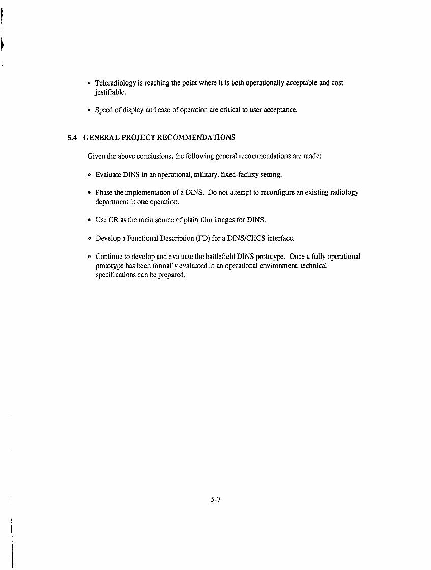
" Teleradiology is reaching the point where it is both operationally acceptable and costjustifiable.
" Speed of display and ease of operation are critical to user acceptance.
5.4 GENERAL PROJECT RECOMMENDATIONS
Given the above conclusions, the following general recommendations are made:
" Evaluate DINS in an operational, military, fixed-facility setting.
" Phase the implementation of a DINS. Do not attempt to reconfigure an existing radiologydepartment in one operation.
" Use CR as the main source of plain film images for DINS.
" Develop a Functional Description (FD) for a DINSICHCS interface.
o Continue to develop and evaluate the battlefield DINS prototype. Once a fully operationalprototype has been formally evaluated in an operational environment, technicalspecifications can be prepared.
5-7

Appendix A
PROJECT BIBLIOGRAPHY
THE MITRE CORPORATION PROJECT DOCUMENTS1 Caudill, M., G. Youngs, A.O. Saarinen, and J.W. Loop, 1989. Radiology Department
Operational Characteristics Prior to Implementation of DIN/PACS: Pre-Installation BaselineStudy Report, Parts I and 11. A Report to The MITRE Corporation DIN/PACS EvaluationProject, Contract No. N55-200, University of Washington Department of Radiology, Seattle,Washington, 60 pp.
2 Mun, S. K., et al, 1988. Baseline Study of Radiology Services for the Purpose of PACSEvaluation. Georgetown University, Washington, D.C.
3 Mun, S. K., et al, 1990. Technical and Clinical Evaluation of Digital Imaging Network.Georgetown University, Washington, D.C.
4 Loop, J. W. et al, 1989. DINS Evaluation Plan and System Evaluation; Part I: ClinicalAcceptability. A Report to the MITRE Corporation DIN/PACS Evaluation Project, ContractNo. N55-200, Uriversity of Washington Department of Radiology, Seattle, Washington.
5 Saarinen, A. 0., G.L. Youngs, and J. W. Loop, 1989b. The Attitude of Clinical PhysiciansToward PACS: A Pre-Installation Assessment. Preliminary Baseline Study Report, Part III. AReport to the MITRE Corporation. University of Washington, Seattle, Washington, -- pp. --1989. A Study of Labor Measurement: DIN/PACS & The University of Washington MedicalCenter. Work Systems Design, Industrial Engineering 317, Winter 1989. University ofWashington, Seattle, Washington.
6 Kim, Y., eLal., 1989. DIN/PACS Prototype Performance Measurement, Computer Model andSimulation at the University of Washington. University of Washington, Seattle, Washington.
7 Kerlin, B.D., J.R. Cerva, and M.E. Glenn, 1987. The Applicability of Digital Imaging for theUS.Army Combat Medical Care System, The MITRE Corporation, McLean, Virginia, WP-86W00426R2.
8 Nadel, L.D., M. E. Glenn, W.P. Johnson, and D.A. Lalko, 1989. Prototype System for DigitalImage Management in Combat Casualty Care. The MITRE Corporation, McLean. Virginia,WP-89W00261.
A-1

9 Nadel, L.D. and W.P. Johnson, 1989. Design of a Prototype Battlefield DINS. The MITRECorporation, McLean, Virginia, MTR-89W00266.
10 Johnson, W.P., 1989. A Description of a Simulation Model Applied to the Digital ImagingNetwork System in Echelon three of Deployable Combat Medical Facilities. The MITRECorporation, McLean, Virginia, MTR-89W00083.
11 Harrington, M.B., 1989. The Results of an Evaluation of a Filmless Radiology System UnderProvision of Army Regulation 40-61. The MITRE Corporation, McLean, Virginia, MTR-89W00152.
12 Cerva, J.R, 1989. The Digital Imaging Network System (DINS) Project Management Plan.The MITRE Corporation, McLean, Virginia, MTR-88W00173.
13 Harrington, M.B. et al, 1988. The Picture Archiving Communications System (PACS)Evaluation Study Plan. The MITRE Corporation, McLean, Virginia, MTR-87W131.
14 Cappelletti, J.D., 1989. Integration Issues Regarding Digital Imaging Network System (DINS)and the Joint Theater Medical Information System (JOTMIS). The MITRE Corporation,McLean, Virginia, MTR-89W00049.
15 Jacobs, B.J., 1989. Design for In Initial Interface Capability Between the Composite HealthCare System (CHCS) and the Digital Imaging Network System (DINS). The MITRECorporation, McLean, Virginia, MTR-89W00049.
16 Cappelletti, J.D., 1989. Integration Issues Regarding Digital Imaging Network Systems (DINS)and the Composite Health Care System(CHCS), The MITRE Corporation, McLean, Virginia,MTR-89W00070.
17 Lafko, D.A., 1989. Software Design of the Prototype Battlefield Digital Imaging NetworkSystem. The MITRE Corporation, McLean, Virginia, MTR-89W00264
39 Kerlin, B.D. and W.P. Johnson, 1989. The Pros and Cons of Various Optical Media for theSoldier's Intefacility Radiographic Record (SIRR) in the Combat Casualty Care System. Paperpresented at the SPIE Medical Imaging Ill Conference, Newport Beach, California.
19 .... 1988. Patient Distribution for the Medical Planning Module. Unpublished Document,USAMRDC, Fort Detrick, MD.
20 Myers, Russ and Michelle Wheeler, 1989. Cost/Benefit Analysis of DIN/PACS at UniversityHospital and Sitka Community Hospitalfor 1988-1989 Masters Project. University ofWashington, Seattle, Washington.
A-2

21 Glenn, M.E., 1989. Image Quality Assurance for Digital Imaging Network System. TheMITRE Corporation, McLean, Virginia, MTR-89W00489.
22 Nadel, L.D., 1989. Evaluation of the Prototype Battlefield Digital Imaging Network System.The MITRE Corporation, McLean, Virginia, MTR-89W00490.
23 Glenn, M.E. and D. A. Lafko, 1989. User's Manualfor a Battlefield Digital Imaging NetworkSystem. The MITRE Corporation, McLean, Virginia, WP-89W00491.
Other References
Funk, COL J., 1987. DEPMEDS Policies/Guidelines Treatment Briefs. USAF and the Joint ServicesClinical Review Group, 5th Edition.
Harrington, M.B., 1989. An Evaluation of Receiver Operating Characteristic (ROC) Analysis as aMethod for Assessing Image Quality in Radiology. The MITRE Corporation, McLean, Virginia,MTR-89W00076.
Harrington, M.B., 1988. The Digital Imaging Network System and its Potential Impact on Quality ofCare in the U.S.Army Peacetime Medical Care System. The MITRE Corporation, McLean, Virginia,WP-87W00513.
Harrington, M. B. and K. D. Miller, 1985. Results of Image Quality Evaluation Conducted inConjunction with the 1984-85 Teleradiology Field Trial. The MITRE Corporation, McLean,Virginia, MTR-85W236.
Johnson, L. et al, 1988. Preliminary Analysis of the Impact of a Digita! Imaging Network and PictureArchiving Communications System at University Hospital. University of Washington, Seattle,Washington.
National Electrical Manufacturer's Association, 1985. Digital Imaging and Communications. ACR-NEMA Standards Publication, 300-1985. Washington, D.C.
Seeley, G.W. and J.D. Newell II, 1984. The Use of Psychophysical Principles in the Design of aTotal Digital Radiology Department. Symposium on Digital Radiography, University of Arizona.
A-3

GEORGETOWN UNIVERSITY: CONFERENCES AND PRESENTATIONS
Benson, H.R., D.E. Madsen, and S.K. Mun: Cost Analysis of an Image Management andCommunication System. SPIE Con:erence on Medical Imaging III, Newport Beach, California,February 1989.
Benson, H.R., and S.K. Mun: Economic Analysis of Developing PACS Network. AAPM SummerSchool, Ann Arbor, Michigan, August 1987.
Benson, H.R.: "Basis IMAC Concepts": Administration and Operations, IMAC 89 (The FirstInternational Conference on Image Management and Communication in Patient Care:Implementation and Impact), June 1989.
Braudes, R.E., C. Green, S.C. Horrii, S.K. Mun, and J. Sibert: Experiences in Building a RadiologyWorkstation Using X-View. Sun Microsystems User Group Conference, 6-8 December 1989,Anaheim, California.
Braudes, R.E., K.E. Hauck, and S.K. Mun: "Advanced Physicians Workbench": An X Windows-Based Workstation. SPIE Conference on Medical Imaging IV, Newport Beach, California, February1990.
Braudes, R.E., B.H. Krasner, J. Schnizlein, J. Sibert, and S.K. Mun: Rapid Prototyping Environmentfor Picture Archiving and Communication System (PACS) Workstation User Interfaces. SPIEConference on Medical Imaging III, Newport Beach, California, February 1989.
Braudes, R.E., S.K. Mun, and S.C.B. Lo: Use of Pixar and Pixel Image Processors for theDevelopment of a Digital Radiology Workstation. Electronic Imaging '88 East, 3 October - 6 October1988, Boston, Massachusetts.
Braudes, R.E., S.K. Mun, J. Sibert, J. Schnizlein, and S. Horii: 'Workstation ModelingDevelopment". Clinical Definition of a Picture Archiving and Communications System (PACS) UserInterface. SPIE Conference on Medical Imaging HI. Newport Beach, California, February 1989.
Braudes, R.E.: ACM SIGCHI'90 Invited Poster Session, 1-5 April, 1990, Seattle Washington
Davros, W.J., J.W. Gaskill, and S.K. Mun: Quality Assurance Protocol for Display Monitors used ina Hospital-Wide IMAC Network. SPIE Conference on Medical Imaging III, Newport Beach,California, February 1989.
A-4

Gaskill, J.W., S.K. Mun, W.J. Davros, and B.A. Levine: Image Quality in Film Digitization andDisplay: "Implications for Teleradiology SPIE Conference on Medical Imaging III", Newport Beach,California, February 1989.
Horii, S.C., and S.K. Mun: A Comprehensive Image Management and Communications System forRadiology: The Clinical Perspective. EuroPACS '89, Bruszie1s, Belgium, March 1989.
Hurii, S.C., H.N. Horii, S.K. Mun, H.R. Benson, and R.K. Zeman: Environmental Designs forReading from Imaging Workstations: Ergonomic and Architectural Features. SPIE Conference onMedical Imaging III, Newport Beach, California, February 1989.
Horii, S.C., B.A. Levine, M.L. Malon-Ingeholm, and S.K. Mun: Validating a Simulation. SPIEConference on Medical Imaging IV, Newport Beach, Valifornia, February 1990.
Horii, S.C., A. Muraki, M.L. Mallon-Ingeholm, S.K. Mun, L. Clark, and D. Schellinger: A CompleteImage Management and Communications Network for the Neuroradiology Service at GeorgetownUniversity Hospital. <fo-5> SPIE Conference on Medical Imaging III, Newport Beach, California,February 1989.
Horii, S.C.: A Review of the ACR-NEMA Digital Imaging and Communications Standards.Electronic Imaging '88, April 1988.
Horii, S.C.: ACR-NEMA Standards Activity: An Update. SPIE Conference on Medical Imaging IV,Newport Beach, California, February 1990.
Horii, S.C.: ACR-NEMA Standards and Magnetic Tape. "IMAC 89 (The First InternationalConference on Image Management and Communication in Patient Care: Implementation andImpact)", Washington, D.C., June 1989.
Horii, S.C.: Clinical Applications. " IMAC 89 (The First International Conference on ImageManagement and Communication in Patient Care: Implementation and Impact)", Washington, D.C.,June 1989.
Horii, S.C.: Clinical Impact of Digital Image Management. "Pleanary Symposia on Images of the21st Century, Engineering in Medicine and Biology Society, Institute of Electrical and ElectronicsEngineers." Seattle, Washington, November 1989.
Levin, K. R. Fielding: Methods to Prefetch Comparison Images in an Image Management andCommunication System (IMACS). SPIE Conference 3n Medical Imaging IV, Newport Beach,California, February 1990.
A-5

Levin, K., S.C. Horii, S.K. Mun, M. Freedman, C. Leftridge, and R.E. Braudes: Analysis of DataAssembling Activities for Radiologists and Its Implications foi Clinical and Operational Acceptanceof PACS. SPIE Conference on Medical Imaging IV, Newport Beach, California, February 1990.
Levine, B.A., H.R. Benson, S.C. Horii, and S.K. Mun: Assessment of the integration of a HIS/RISwith a PACS. SPIE Conference on Medical Imaging III, Newport Beach, California, February 1989.
Levine, B.A. M. Meissner, H.R. Benson, C. Bzarth, and S.K. Mun: Integration of a RadiologyInformation System (RIS) with an Image Management and Communication System (IMACS): AComparative Analysis SPIE Conference on Medical Imaging III, Newport Beach, California,February 1989.
Levine, B.A., M. Meissner, K. Randall, and S.K. Mun: Performance Analysis of the GUHPACS:Modeling and Validation. 7th EuroPACS Conference, Brussels, Belgium, March 1989.
Levine, G.A., K. Randall, and G.S. Plumlee: Performance Analysis of PACS: Modeling andSimulation. 1 Ith Annual International Conference, Engineering in Medicine and Biology Scoiety,Institute of Electrical and Electronics Engineers, Seattle, Washington, November 1989.
Levine, B.A., K. Randall, S.K. Mun, H.R. Benson, and M. Meissner: Optimization of PictureArchiving and Communication Systems (PACS) Network Performance: Simulation and Validation.SPIE Conference on Medical Imaging III, Newport Beach, California, February 1989.
Levin, B.A.: Managing a Medical Image Database: Design and Operational Issues. ElectronicImaging West '90. Pasadena, California, March 1990.
Levine, B.A.: PACS Integration into the Radiology Department at Georgetown University Hospital.5th Arm,jal International Conference on Computerization of Medical Records, Anaheim, Califorma,April 1989.
Lo, S.C.B., and S.K. Mun: Data Compression for a Radiology Image Display System with VisualDirectory. SPIE Conference on Medical Imaging II, Newport Beach, California, February 1988.
Lo, S.C.B, S.C. Horii, S.K. Mun, R. Braudes, and B. Garra: Development of pictorial DirectoryWorkstation for Rapid Image Presentation. SPIE Conference on Medical Imaging III, NewportBeach, California, February 1989.
A-6

Lo, S.C B., Y. Kim. D.R. Haynor, H.R. Benson, A.H. Rowberg, M. Greberman, R. Allman and J.W.Loop: Experiences in Implementation, Clinical Acceptance, and Operations of ComprehensiveRadiology Networks. SPIE Conference on Medical Imaging III, Newport Beach, California, February1989.
Lo, S.C B., B.H. Krasner, and S.K. Mun: Impact of Random Noise on Radiological ImageCompression. SPIE Conference on Medical Imaging III, Newport Beach, California, February 1989.
Lo, S.C B., B.H. Krasner, and S.K. Mun: Implementation Consideration of a Compression Modulefor a PAC System. Medical Infomatic. Beijing china, Octover, 1989.
Lo, S.C. B., J.W. Gaskill, B.H. Krasner, and S.K. Mun: Image Information in Film Digitization andDisplay Monitor - Implication for Teleradiology. SPIE Conference on Medical Imaging III, NewportBeach, California, February 1989.
Lo, S.C.B., S.C. Mun, R.E. Braudes, B.A. Levine, A. Muraki, and B. Garra: Radiology ReportingStation Modeling and Implementation. The 5th International Symposium on PACS. 7 July-9 July1988, Tokyo, Japan.
Mallon-Ingeholm, M.L.: A Hospital-Wide Network at Georgetown University Hospital. AmericanAssociation for Medical Instrumentation, St. Louis, Missouri, May 1989.
Mun, I.K., and S.K. Mun: Radiology Workstations. The 5th Asian-Oceanic Congress of Radiology,Seoul, Korea. Octover, 1987.
Mun, S.K., H.R. Benson, and L.P. Elliott: Development and Operational Evaluation of PACSNetwork at Georgetown University. Medical Imaging III, Vol. 914, pp.1334-1340, 1988.
Mun, S.K., H.R. Benson, S.C. Horii, L.P. Elliott, S.C.B. Lo, B. Levine, R. Braudes, G. Plumles, B.Garra, D. Schellinger, and B.P. Majors: Completion of a Hospital-Wide Comprehensive ImageManagement and Communication System. SPIE Conference on Medical Imaging III, Newport Beach,California, February 1989.
Mun, S.K., and H.R. Benson: Total Digital Radiology Department: Implementation Strategy andRequirements. SPIE Conference on Medical Imaging 1II, Newport Beach, California, February 1989.
A-7

Mun, S.K. S.C. Horii, H.R. Benson: Picture Archiving and Communication in Radiology: AnAmerican Perspective. Hokkaido University School of Medicine, Sapporo, Japan, December 1989.
Mun, S.K. and S.C. Horii: Experience with a Hospital-Wide Image Management and CommunicationSystem: Is Filmless Radiology Possible? IMA GO 90 conference, Bologna, Italy, 1989.
Mun, S.K: Chairman: IMAC 89 (the First International Conference on Image Mangement inCommunication in Patient Care: Implemer, tation and Impact), Washington, D.C., June 1989.
Mun, S.K: Chairman: Plenary Symposia on Images of the 21st Century, Engineering in Medicineand Biology Scoiety, Institute of Electrical and Electronics Engineers. Seattle, Washington,November 1989.
Mun, S.K: Comprehensive Digital Imaging Network Project: System Implementation and ClinicalEvaluation. SPSE's 41st Annual Conference, Washington, D.C. May 1988.
Mun, S.K: Design and Development of PACS. The 5th Asian-Oceanic Congress of Radiology,Seoul, Korea. October 1987.
Mun, S.K.: Development and Evaluation of a Comprehensive PACS network as a part of DINSProgram. Keynote Address, Japar, PACS Society Annual Meeting, Tokyo, Japan July, 1987.
Mun, S.K: Implementation Strategy of Image Management Network. Japan Radiology Contress,Tokyo, Japan. February, 1988.
Mun, S.K: PACS Network Performance. Japan Nuclear Medicine contress Special Session, Tokyo,Japan, October 1988.
-,;un, S.K: Performance Analysis of PACS Workstation. Electronic Imaging Conference, Boston.October 1987.
Mun, S.K: Performance Evaluation of Electronic Workstations. AAPM Summer School, Ann Arbor,Michigan. August, 1987.
Mun, S.K: Progress in Digital Imaging Network Development and Evaluation Project. PACSCommittee Japan Radiology Socicy, Tokyo, Japan. February, 1988.
Mun, S.K: Progress Report of Digital Network Development at Evaluation Project. EuroPACSAnnual Meeting, Utrecht, Holland. April, 1989.
A-8

Mun, S.K: Technical Overview of PACS Development. AUR-AAPM Symposium on DigitalImaging, New Orleans, Louisiana. March, 1988.
Plumlee, G.S., H.R. Benson, S.K. Mun, and F. Goeringer: Cost Analysis Model of Digital ImagingNetwork Systems (CAMDIN): Results of a Comprehensive Sensitivity Analysis. SPIE Conference onMedical Imaging IV, Newport Beach, California, February 1990.
Plumlee, G.S. S.C. Horii, S.K. Mun, R.E. Braudes, and F. Goeringer: Teaching File-BasedWorkstations for Radiology. SPIE Conference on Medical Imaging IV, Newport Beach, California,February 1990.
A-9

UNIVERSITY OF WASHINGTON: CONFERENCES AND PRESENTATIONS
Bartoo, G. T., Kim, Y., Haralick, R. M., Nochlin, D., and Sumi, S. M., MathematicallyMorphology Techniques for Image Processing Applications in Biomedical Imaging. SPIE MedicalImaging '88 Conference, Vol. 914, pp. 466-475, 1988.
Choi, H. S., Haynor, D. R., and Kim, Y., Multivariate Tissue Classification of MRI Images for 3-DVolume Reconstruction - A Statistical Approach. SPIE Medical Imaging 'T9, Vol. 1092, pp. 183-193,1989.
Choi, H. S., Park, H. W., Haynor, D. R., and Kim, Y., Development of a Prototype ElectronicAlternator for DINIPACS Environment and its Evaluation. SPIE Medical Imaging IV, Vol 1234, inpress. 1990.
DeSoto, L. A., Choi, I. S., Burchiel, K. J., Haynor, D. R., Kim, Y., and Roberts, T. S., MultiplanarImaging System for Stereotaxic Neurosurgery. SPIE Medical Imaging '89, Vol. 1091, pp. 31-41,1989.
DeSoto, L. A. and Kim, Y., Implementations Issues of DIN/PACS. Electronic Imaging Spring '87,pp. 405-410, 1987.
Fahy, J. B. and Kim, Y., A Consistent DINIPACS Workstation Interface Based on MUVIP VirtualImage Processing Architecture. SPIE Medical Imaging '88 Conference, Vol. 914, pp. 911-919, 1988.
Gee, J. C., Barfield, W., Haynor, D. R., and Kim, Y., The Design and Analysis of a Medical ImagingWorkstation. Third International Conference on Humannn-Computer Interaction, in press 1989
Gee, J. C., DeSoto, L. A., Haynor, D. R., Kim, Y., and Loop, J. W., User Interface Design for aRadiological Imaging Workstation. SPIE Medical Imaging '89, Vol. 1093, pp. 122-132, 1989.
Gee, J., Barfield, W., Haynor, D. R., and Kim, Y., User nerface Design for a Medical ImagingWorkstation. Image Presentation and Processing Issues. International Journal of Human-ComputerInteraction, submitted, 1989.
Gee, J. C., DeSoto, L. A., and {im, Y., User Interface Design for a Radiological ImagingWorkstation. SPIE Medical imaging 1989, Vol. 1093, pp. 122-132.
Greberman, M., Mun, S. K., Loop, J. W., Goeringer, F., Kerlin, B., The US. Digital Imaging Project:Program Notes. First Na..ional Conference on Image Management and Communication in PatientCases, Utrecht/Leiden, The Netherlands, April, 1988, pp. 209-212
A-10

Haynor, D. R., Rowberg, A. H., and Loop, J. W., Clinical Evaluation of a Prototype Digital ImagingNetwork. SPIE Medical Imaging 1988, Vol. 914, pp. 1432-1443.
Haynor, D., Weghorst, S., Saarinen, A., Loop, J., and Schmiedl, U., Clinical Evaluation of PACSWorkstation--Methodology and Results. SPIE Medical imaging 1990.
Haynor, D. R., The Old Study and The Correlative Study, Implications for PACS. SPIE MedicalImaging 1989, Vol. 1093, pp. 10-12.
Kim, Y., Miyaoka, R. S., and Choi, H. S., Review of Low-cost Image Processing Systems forBiomedical Applications. IEEE EMBS Nith Annual Conference, pp. 1342-1344, 1987.
Kim, Y., Fahy, J. B., DeSoto, L. A., Haynor, D. R., and Loop, J, W., Development of a PC-basedRadiological Imaging Workstation. SPIE Medical Imaging '88 Conference, Vol. 914, pp. 1257-1264,1988.
Kim, Y., Haynor, D. R., Saarinen, A. 0., Rowberg, A. H., and Loop, J. W., Preliminary PACSExperience at the University of Washington. Electronic Imaging Spring '89, pp. 142-147, 1989.
Lee, W., Rowberg, A. H., O'Leary, Y. W., and Kim,, Y., Integrating a Radiology Information Systemwith a Picture Archiving and Communications System. SPIE Medical Imaging IV, Vol. 1234, inpress, 1990.
Loop, J. W., Haynor, D., Weghorst, S., and Schmiedl, U., Radiologists' Preferences in PACSWorkstations. EuroPACS 1990, Italy.
Loop, J. W., Rowberg, A., Saarinen, A., Lewellen, T., Haynor, D., Trivedi, V., Kim, Y., and O'Leary,Y., Evaluation of a Digital Imaging Network: A Multidisciplinary Approach. In planningConsiderations in Diagnostic Imaging and Radiation Theory, Editors, A. Chiesor, R. Gasporotti, R.Marldi, F. Apollonio, Brescia (Italy) April, 1988, pp. 209-212.
Loop, J. W., Evaluation of Picture Archiving and Communication: Current Status of a GovernmentSponsored Project at Two University Medical Centers. Proceedings of the Third InternationalSymposium on PACS and PHD, Tokyo, July 9-11, 1986.
Marglin, S. I., Rowberg, A. H., and Godwin, D. J., Preliminary Experience with Portable DigitalImaging for Intensive Care Radiology. I. Thorac Imag, 1990.
Mun, S. K., Benson, H., and Elhott, L. P., Goeringer, F., Saarinen, A., and Haynor, D., Total DigitalDepartment: Implementation Strategy. SPIE Medical Imaging 1989, Vol. 1093, pp.133-139.
Mun, S. K., Hori, S., Benson, H., and Lo, S. H., Haynor, D., Saarinen, A., Kim, Y., Loop, J.,Greberman, M., and Allman, R., Experience with Image Management Networks at Three
A-11

Universities: Is the Cup Half-Empty or Half -Full? SPIE Medical Imaging 1989. Vol. 1093, pp. 194-201.
Nelson, A. C., Kim, Y., Haralick, R. M., Andersson, P. A., Johnson, R. H., and DeSoto, L. A., Stereoand Multiplanar Video Display for 3-D Magnetic Resonance Image Data. Journal of ImagingTechnology, Vol. 15, pp. 74-78, 1989.
Nelson, A. C., Kim, Y., Haralick, R. M., Anderson, P. A.,Johnson, R. H., and DeSoto, L. A., 3-DDisplay of Magnetic Resonance Imaging of the Spine. SPIE Conference on Three-DimensionalImaging and Remote Sensing Imaging, Vol. 902, pp.103-112, 1988.
Panwar, R. K., Wang, C. S., DeSoto, L. A., Park, H. W., and Kim, Y., University of WashingtonPACS Prototype Performance Measurements, Computer Model, and Simulation. SPIE MedicalImaging IV, Vol. 1234, in press, 1990.
Rowberg, A. H., O'Leary, Y. M., and Loop, J. W., Interfacing a Radiology Information System to anImage Database System. Computer Applications in Radiology, RISC/ACR, June 1988.
Rowberg, A. H., Clinical Overview of IMAC Systems. IMAC, 1989.
Saarinen, A. 0., Haynor, D. R., Loop, J. W., Johnson, L., Russell, j., Mitchell, K., and Nemerever,M., Modeling the Economics of PACS: What is Important? SPIE Medical Imaging 1989, Vol. 1093,pp. 62-73.
Saarinen, A. 0., Goodsitt, M. M., and Loop, J. W., The Logistics of Installing PACS in an ExistingMedical Center. SPIE Medical Imaging 1989, Vol. 1093, pp. 159-170.
Saarinen, A. 0., Youngs, G., Haynor, D. R., and Loop, J. W., Clinical Determinants of PACSAcceptance. SPIE Medical Imaging 1990.
Saarinen, A. 0., Wilson, M. C., Iverson, S. C., Haynor, D. R., and Loop, J. W., PACS Economics andthe Referring Physician. SPIE Medical Imaging 1990.
Saarinen, A. 0., Wilson, M. C., Iverson, S. C., and Loop, J. W., Potential Time Savings to RadiologyDepartment Personnel in a PACS-Based Environment. SPIE Medical Imaging 1990, Vol. 1234:261.
Wilhelm, P., Haynor, D. R., Kim, Y., Nelson, A. C., and Riskin, E. A., Lossy Image Compression forDigital Medical Imaging Systems. SPIE Medical Imaging IV, Vol. 1232, in press, 1990.
A-12

OTHER DIN/PACS RELJTED TECHNICAL REPORTS
Caudill, M., Youngs, G., Saarinen, A. 0., and Loop, J. W., Radiology Department OperationalCharacteristics Prior to Implementation of DIN/PACS. A Report to the MITRE Corporation,Contract No. N55200, November, 1989, 60 pp.
Haynor, D. R., Johnson, L., and Saarinen, A. 0., An Economic Evaluation of a Digital ImagingNetwork System at Madison Army Medical Center. A Report Prepared for the US Army SurgeonGeneral, April, '88, 60 pp.
Loop, J. W., Haynor, D. R., Weghorst, S., Ramey, J., Saarinen, A. 0., and Youngs, G., The Clinicaland Technical Evaluation of PACS at the University of Washington Medical Center. A Report to theMITRE Corporation, Contract No. N55200, December, 1989, 232 pp.
Saarinen, A. 0., Youngs, G., and Loop, J. W., The Attitude of Referring Physicians Towards PACS: APreinstallation Assessment. A Report to the MITRE Corporation, Contract No. N55200, November,1989, 71 pp.
A-13

GLOSSARY
ACR American College of RadiologyAM Acquisition ModuleAT&T American Telephone and Telegraph
CAT Computer Aided TomographyCC Consultation ConsoleCHCS Composite Health Care SystemCOMMZ Communications ZoneCONUS Continental United StatesCR Computed RadiographyCRT Cathode Ray TubeCSH Combat Support HospitalCT Computed Tomography
DECrad Digital Equipment Corporation Radiology Information SystemDEMPEDS Deployable Medical SystemDINS Digital Imaging Network SystemDoD Department of Defense
EGDW Enhanced Graphics Display WorkstationEMT Emergency Medical TreatmentEVAC Evacuation Hospital
FD Functional DescriptionFIDS Filmless Digital Imaging SystemFLOT Forward Line of Own Troops
GUMC Georgetown University Medical Center
HI-CAP High Capacity X-ray UnitHIS Hospital Information SystemHSS Health Services Support
ICU Intensive Care UnitICW Intermediate Care WardID IdentificationIFD Interface Functional DescriptionIMACS image Management and Communication SystemISO International Standards Organization
JOTMIS Joint Theater Medical Information System
GL-1

LAN Local Area NetworkLO-CAP Low Capacity X-ray UnitKBPS Kilobits Per Second
MAMC Madigan Army Medical CenterMASH Mobile Army Surgical HospitalMB MegabytesMBPS Megabits Per SecondMCW Minimal Care WardMF2K Medical Force Two ThousandMIC Montgomery Imaging CenterMUS Meditech Interpretive Information SystemMRI Magnetic Resonance ImagingMTF Medical Treatment FacilityMTR MITRE Technical ReportMUMPS Massachusetts General Hospital Utility Multi-Programming System
NEMA National Electrical Manufacturer's AssociationNMR Nuclear Magnetic Resonance
OR Operating Room
PACS Picture Archiving and Communication SystemPCR Philips Computed RadiographyPDIP Program Decision Increment PackagePET Positron Emission Tomography
Rad RadiologicalRIS Radiology Information SystemROC Receiver Operating CharacteristicRTD Returned to DutyRVS Results Viewing StationRVU Remote Viewing Unit
SCSI Small Computer Systems InterfaceSIRR Soldier's Interfacility Radiographic Record
UCA Uniform Chart of AccountsUSAMRDC U.S. Army Medical Research and Development CommandUWMC University of Washington Medical Center
WORM Wnte Once, Read Many
VAMC Veterans Administration Medical Center
GL-2

DAT E: , ~ tI
LIQIn

SUPPLEMENTARY,
INFORMATION

------ AD 79 '7
MTR-90W00040
Filmless Radiology: The Design,Integration, Implementation, and Evaluation
of a Digital Imaging Network
Annual and Final Report
John R. CervaBarbara D. Kerlin, Ph.D.
Leon S. Pocinki, Sc.D.
DOD DISTRIBUTION STATEMENTApproved for public release; distribution unlimited.
aThe findings in this report are not to be construed as
o an official Department of the Army position unless sodesignated by other authorized documents.
Supported byU.S. Arnpy Medical Research and Development Command
Fort Detrick, Frederick, Maryland 21701-5012
Contract No. DAMD17-86-C-6145
The MITRE Corporation7525 Colshire Drive
McLean, Virginia 22102-3481