1 2/10/2005thrust chamber assembly concept design review components of tca injector chamber nozzle
Post on 20-Dec-2015
217 views
TRANSCRIPT
2/10/2005 Thrust Chamber Assembly Concept Design Review
1
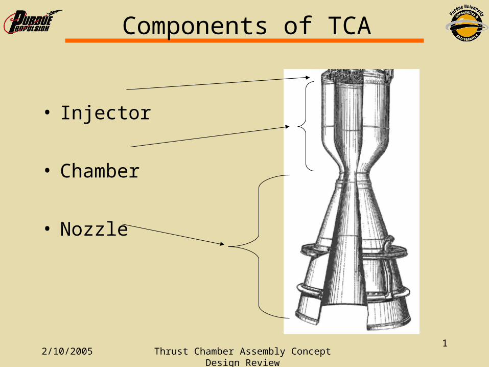
Components of TCA
• Injector
• Chamber
• Nozzle
2/10/2005 Thrust Chamber Assembly Concept Design Review
2
• The first step in the design was to pick propellants– LOX – propylene chosen for several reasons
• Customer has experience and access
• Allow for partial self pressurization of propellant tanks
• The mixture ratio is specified by CSULB based on the ratio that will give the best operability = 2.27. This allows for the propellant tanks to empty at the same rate
• A chamber pressure must be chosen– 300 psi was chosen by the customer.
• Current tanks can handle 450 psi 300 psi chamber pressure after losses
• Cooling by passive means is possible (No dump or regenerative cooling required)
Design Process
2/10/2005 Thrust Chamber Assembly Concept Design Review
3
• With the information available we run the NASA thermochemistry code to obtain some useful data:– Chamber Temp (Tc) = 6341 R
– C* = 6044 ft/s
– Exit pressure (pe) = 5.66 psi
– Exit velocity (ve) = 9627.8 ft/s
– Cfvac = 1.593
– Specific heat ratio γ = 1.1398
– Molecular weight = 21.313
– Ispvac = 327.6 s
Design Process
2/10/2005 Thrust Chamber Assembly Concept Design Review
4
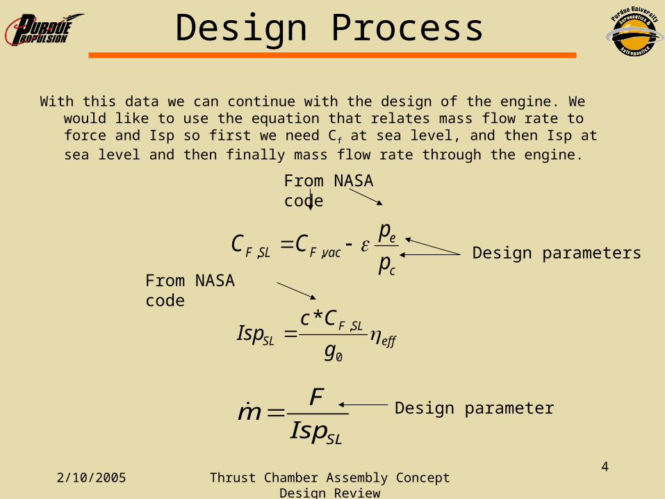
With this data we can continue with the design of the engine. We would like to use the equation that relates mass flow rate to force and Isp so first we need Cf at sea level, and then Isp at sea level and then finally mass flow rate through the engine.
c
evacFSLF p
pCC ,,
effSLF
SL g
CcIsp
0
,*
SLIsp
Fm
From NASA code
Design parameters
From NASA code
Design parameter
Design Process
2/10/2005 Thrust Chamber Assembly Concept Design Review
5
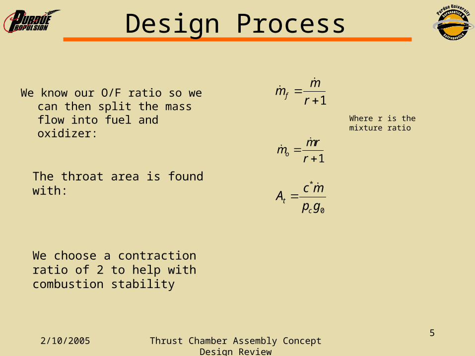
We know our O/F ratio so we can then split the mass flow into fuel and oxidizer:
1r
mm f
1r
rmmo
Where r is the mixture ratio
The throat area is found with:
We choose a contraction ratio of 2 to help with combustion stability
0
*
gp
mcA
ct
Design Process
2/10/2005 Thrust Chamber Assembly Concept Design Review
6
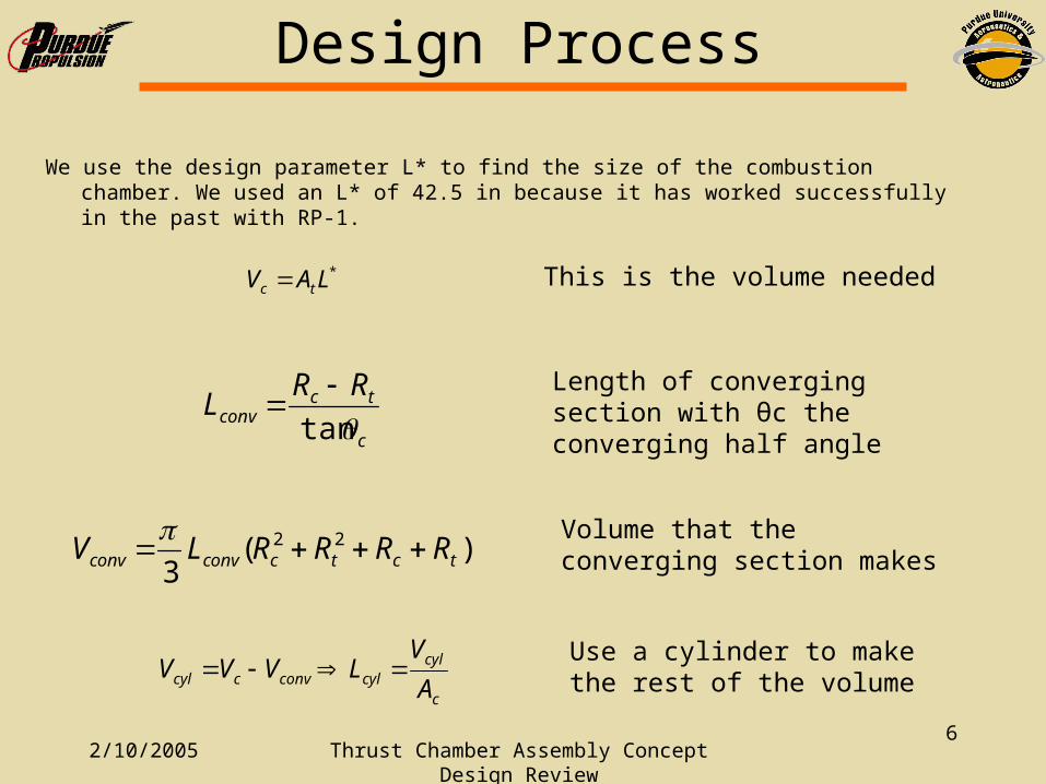
We use the design parameter L* to find the size of the combustion chamber. We used an L* of 42.5 in because it has worked successfully in the past with RP-1.
*LAV tc This is the volume needed
c
tcconv
RRL
tan
Length of converging section with θc the converging half angle
)(3
22tctcconvconv RRRRLV
Volume that the converging section makes
c
cylcylconvccyl A
VLVVV
Use a cylinder to make the rest of the volume
Design Process
2/10/2005 Thrust Chamber Assembly Concept Design Review
7
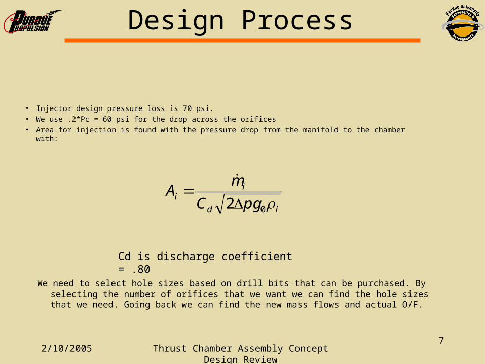
• Injector design pressure loss is 70 psi.
• We use .2*Pc = 60 psi for the drop across the orifices
• Area for injection is found with the pressure drop from the manifold to the chamber with:
id
ii
pgC
mA
02
Cd is discharge coefficient = .80
Design Process
We need to select hole sizes based on drill bits that can be purchased. By selecting the number of orifices that we want we can find the hole sizes that we need. Going back we can find the new mass flows and actual O/F.
2/10/2005 Thrust Chamber Assembly Concept Design Review
8
Design Requirements – Chamber
• L* = 42.5 in• Should withstand heat flux for burn time• Should withstand any transient pressure• Should not be overly complicated (Cheap to build)• Cannot use regenerative cooling because of lack
of pressure budget• Use ablative liner and film cooling or O/F bias.• Convergence ratio of 2• Need to be able to flange onto injector
2/10/2005 Thrust Chamber Assembly Concept Design Review
9
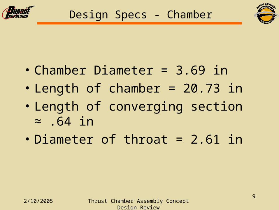
Design Specs - Chamber
• Chamber Diameter = 3.69 in
• Length of chamber = 20.73 in
• Length of converging section ≈ .64 in
• Diameter of throat = 2.61 in
2/10/2005 Thrust Chamber Assembly Concept Design Review
10
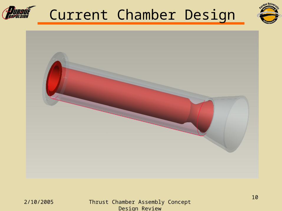
Current Chamber Design
• Put drawing here
2/10/2005 Thrust Chamber Assembly Concept Design Review
11
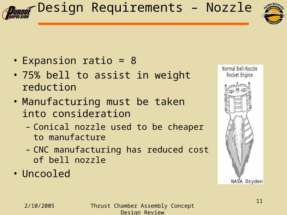
Design Requirements – Nozzle
• Expansion ratio = 8• 75% bell to assist in weight reduction• Manufacturing must be taken into
consideration– Conical nozzle used to be cheaper to
manufacture
– CNC manufacturing has reduced cost of bell nozzle
• UncooledNASA Dryden

2/10/2005 Thrust Chamber Assembly Concept Design Review
12
Design Specs - Nozzle
• Length of nozzle – 8.91 in (15° cone)– 7.13 in (80% bell)
• 75% Bell– Lower Weight– Better Performance
Bell Nozzle on Pump-Fed LRE

2/10/2005 Thrust Chamber Assembly Concept Design Review
13
Current Nozzle Design
2/10/2005 Thrust Chamber Assembly Concept Design Review
14
Design Requirements - Injector
• By far the most complicated part of design• ΔP = 70 psi• Shouldn’t melt or scorch• Provide combustion stability• No inter-propellant seals• Total flow rate = 8.45 lbm/s• Ox flow rate = 5.87 lbm/s• Fuel Flow rate = 2.58 lbm/s
2/10/2005 Thrust Chamber Assembly Concept Design Review
15
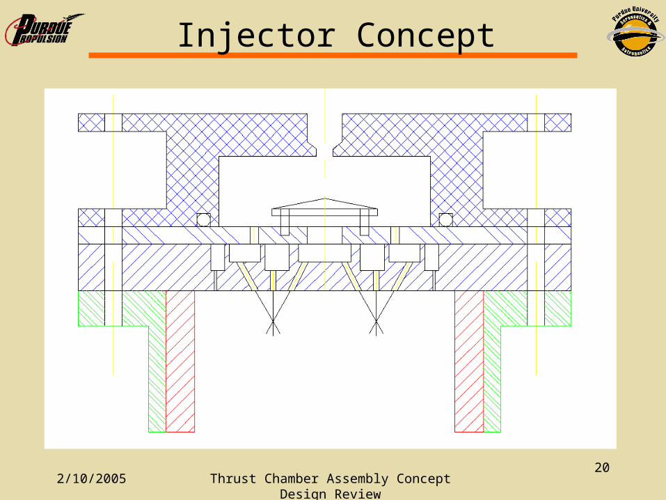
O-F-O Impinging Injector
• Injector provides for propellant mixing by impinging jets. Two oxidizer jets impinge on one fuel jet.
O OF
Fan
2/10/2005 Thrust Chamber Assembly Concept Design Review
16
O-F-O Injector
• Well known design process• Better performance compared to pintle• Allows for O/F biasing against wall and
film cooling• Propellants are well suited for this option
– SG propylene = .5– SG LOX = 1.14– O/F = 2.27
2/10/2005 Thrust Chamber Assembly Concept Design Review
17
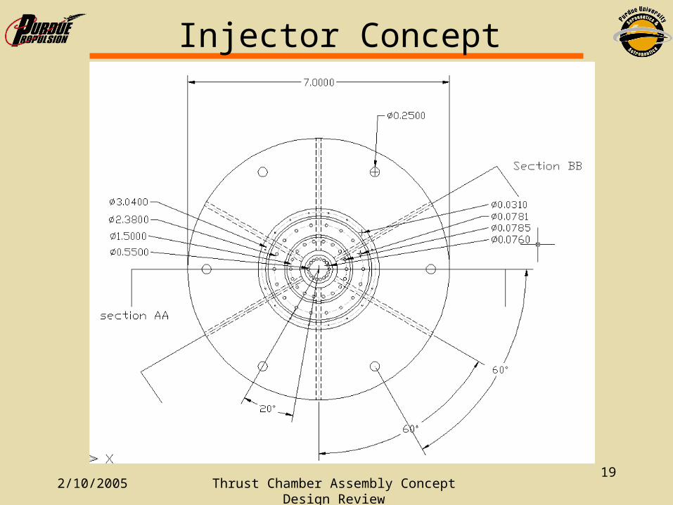
Injector Sizing
• 18 – triplets • 18 film cooling elements• Oversize outboard oxidizer element to
ensure jets stay away from the wall• Impingement point length/ diameter of
orifice should be ~ 5• Bore length/diameter of orifice should be >
3.5 to ensure Cd = .80• Manifolds – 10*area of orifices they feed
2/10/2005 Thrust Chamber Assembly Concept Design Review
18
Injector Concept
2/10/2005 Thrust Chamber Assembly Concept Design Review
19
Injector Concept
2/10/2005 Thrust Chamber Assembly Concept Design Review
20
Injector Concept
• Put the picture here
2/10/2005 Thrust Chamber Assembly Concept Design Review
21
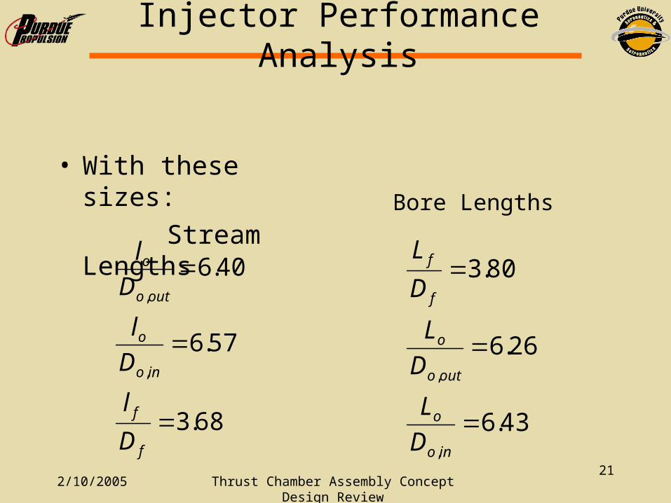
Injector Performance Analysis
• With these sizes:
Stream Lengths
68.3
57.6
40.6
,
,
f
f
ino
o
outo
o
D
l
D
l
D
l
43.6
26.6
80.3
,
,
ino
o
outo
o
f
f
D
L
D
L
D
L
Bore Lengths
2/10/2005 Thrust Chamber Assembly Concept Design Review
22
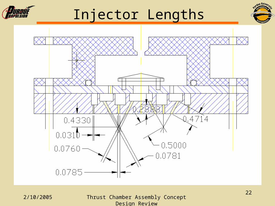
Injector Lengths
2/10/2005 Thrust Chamber Assembly Concept Design Review
23
Manifold Sizes
2/10/2005 Thrust Chamber Assembly Concept Design Review
24
Manifold Sizes
2/10/2005 Thrust Chamber Assembly Concept Design Review
25
Manifold Sizes
• Aox,in = .08165 in2
• Aox,out = .01437 in2
• Afuel = .01452 in2
• Afilm = .00226 in2
• Flow Area/ Injection Area• Oxin = 2.296• Oxout = 7.738• Fuel = 9.043• Film = 33.186
2/10/2005 Thrust Chamber Assembly Concept Design Review
26
Injector performance
• Velocities:– Ox = 88.35 ft/s– Fuel = 120.45 ft/s
• Momenta– Ox_out = 222 lb-in/s2
– Ox_in = 210 lb-in/s2
– Fuel = 224 lb-in/s2
0.9911 : 1.0000 : 0.9375

2/10/2005 Thrust Chamber Assembly Concept Design Review
27
Injector Fill Times
Volumes
Vox = 7.13508 in3
Vf = .26875 in3
Volumetric flows
Qox = 142 in3/s
Qf = 118.5 in3/s
Fill times
tox= .05 sec
tfuel= .002 sec
2/10/2005 Thrust Chamber Assembly Concept Design Review
28
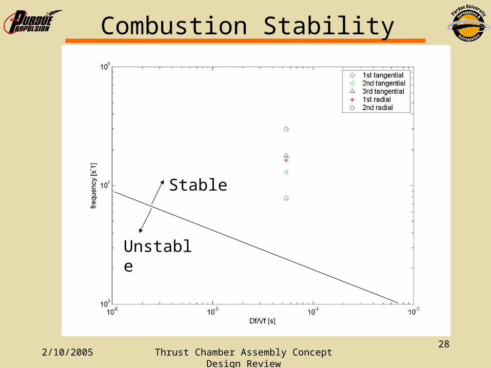
Combustion Stability
Stable
Unstable
2/10/2005 Thrust Chamber Assembly Concept Design Review
29
Current Concept Summary
• Injector: O-F-O Injector
• Chamber: Ablative Lining
• Nozzle: 80% Bell
Picture here
2/10/2005 Thrust Chamber Assembly Concept Design Review
30
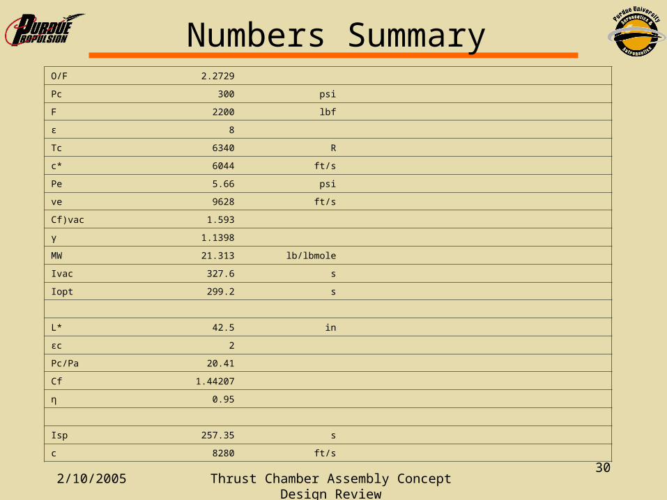
Numbers SummaryO/F 2.2729
Pc 300 psi
F 2200 lbf
ε 8
Tc 6340 R
c* 6044 ft/s
Pe 5.66 psi
ve 9628 ft/s
Cf)vac 1.593
γ 1.1398
MW 21.313 lb/lbmole
Ivac 327.6 s
Iopt 299.2 s
L* 42.5 in
εc 2
Pc/Pa 20.41
Cf 1.44207
η 0.95
Isp 257.35 s
c 8280 ft/s
2/10/2005 Thrust Chamber Assembly Concept Design Review
31
Numbers
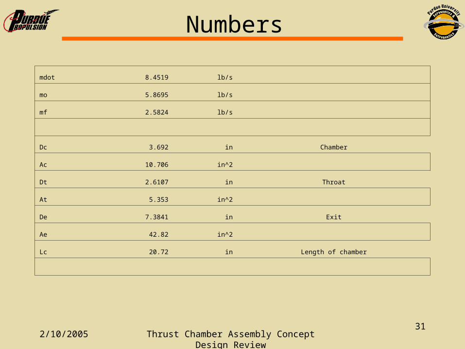
mdot 8.4519 lb/s
mo 5.8695 lb/s
mf 2.5824 lb/s
Dc 3.692 in Chamber
Ac 10.706 in^2
Dt 2.6107 in Throat
At 5.353 in^2
De 7.3841 in Exit
Ae 42.82 in^2
Lc 20.72 in Length of chamber
2/10/2005 Thrust Chamber Assembly Concept Design Review
32
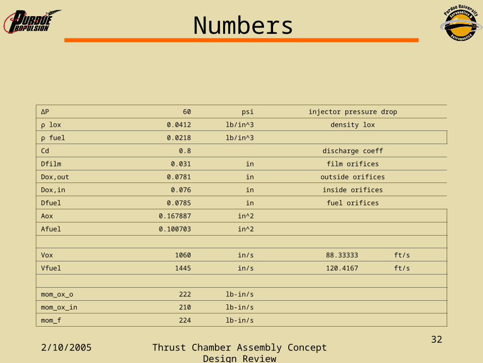
Numbers
ΔP 60 psi injector pressure drop
ρ lox 0.0412 lb/in^3 density lox
ρ fuel 0.0218 lb/in^3
Cd 0.8 discharge coeff
Dfilm 0.031 in film orifices
Dox,out 0.0781 in outside orifices
Dox,in 0.076 in inside orifices
Dfuel 0.0785 in fuel orifices
Aox 0.167887 in^2
Afuel 0.100703 in^2
Vox 1060 in/s 88.33333 ft/s
Vfuel 1445 in/s 120.4167 ft/s
mom_ox_o 222 lb-in/s
mom_ox_in 210 lb-in/s
mom_f 224 lb-in/s
2/10/2005 Thrust Chamber Assembly Concept Design Review
33
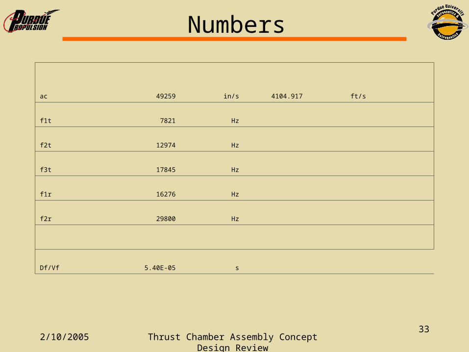
Numbers
ac 49259 in/s 4104.917 ft/s
f1t 7821 Hz
f2t 12974 Hz
f3t 17845 Hz
f1r 16276 Hz
f2r 29800 Hz
Df/Vf 5.40E-05 s
2/10/2005 Thrust Chamber Assembly Concept Design Review
34
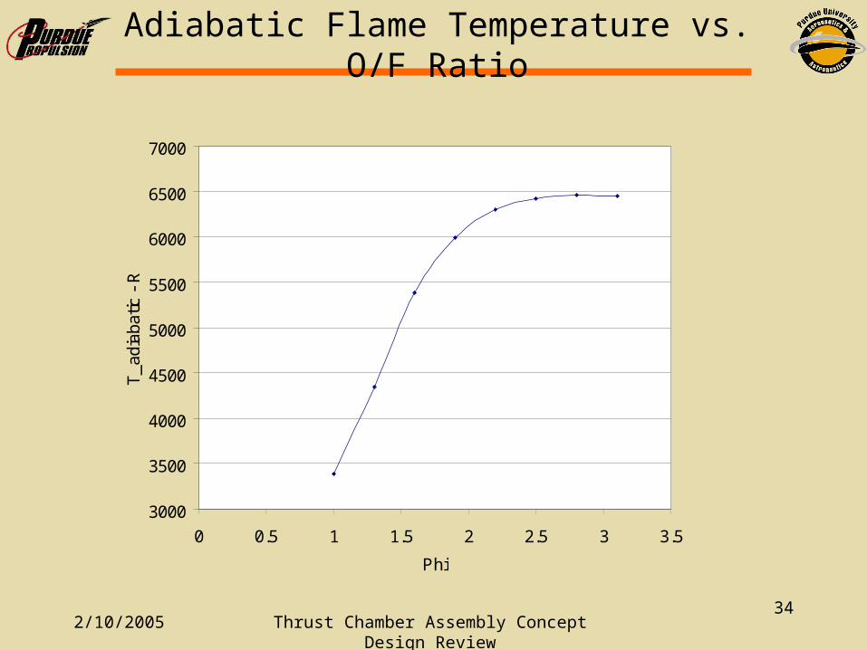
Adiabatic Flame Temperature vs. O/F Ratio
3000
3500
4000
4500
5000
5500
6000
6500
7000
0 0.5 1 1.5 2 2.5 3 3.5
Phi
T_a
diab
atic
- R
2/10/2005 Thrust Chamber Assembly Concept Design Review
35
5000
5200
5400
5600
5800
6000
6200
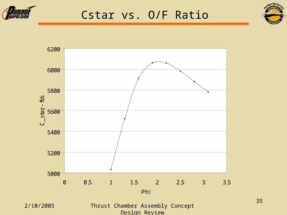
0 0.5 1 1.5 2 2.5 3 3.5
Phi
C_s
tar
- ft/
s
Cstar vs. O/F Ratio
2/10/2005 Thrust Chamber Assembly Concept Design Review
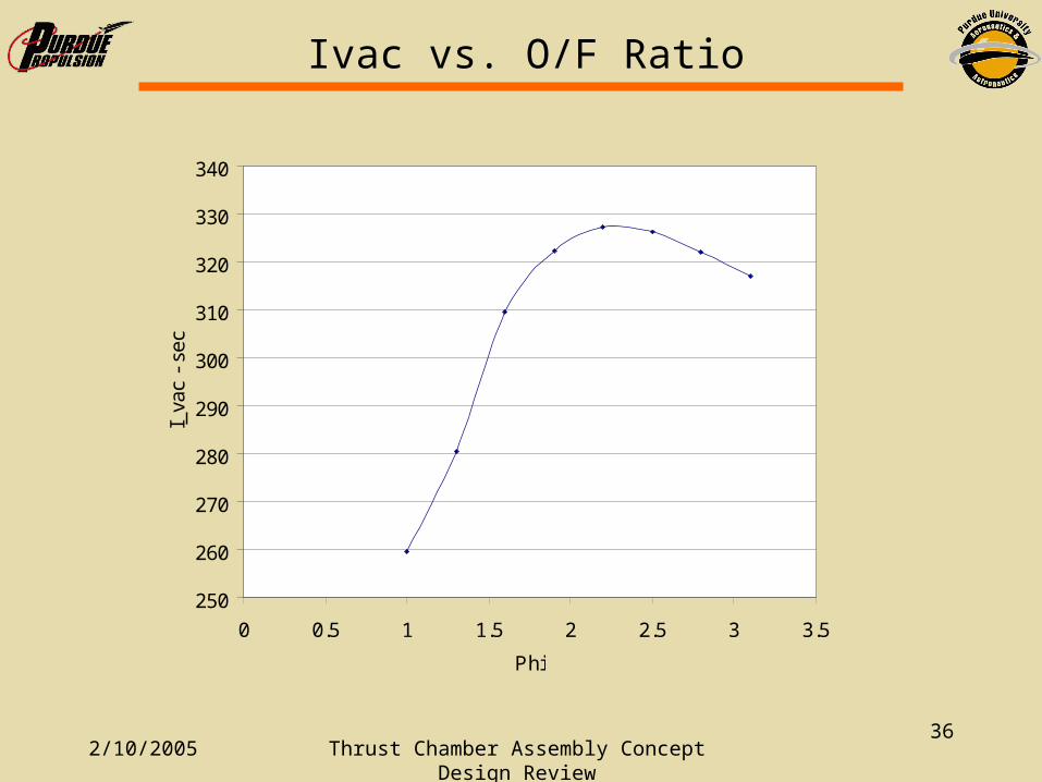
36
250
260
270
280
290
300
310
320
330
340
0 0.5 1 1.5 2 2.5 3 3.5
Phi
I_va
c -
sec
Ivac vs. O/F Ratio

2/10/2005 Thrust Chamber Assembly Concept Design Review
37
1.5
1.51
1.52
1.53
1.54
1.55
1.56
1.57
1.58
1.59
1.6
0 0.5 1 1.5 2 2.5 3 3.5
Phi
Thr
ust C
oeffi
cien
t
Thrust Coefficient vs. O/F Ratio