and electromagnetic injector - university of california,...
TRANSCRIPT
Status of Target Injector, In-Chamber Tracking, and Electromagnetic Injector
Ronald Petzoldt, Dan Goodin, Neil Alexander, Gottfried Besenbruch,Walt Egli, Leslie Evans, John Follin, Dane Fricker, Chuck Gibson, MikeGouge, Michael Hollins, Kevin Jonestrask, and Dennis Lieurance
HAPL Project Review Pleasanton, CA November 13, 2001

Overview/Summary
Status of injector• Design status• Selected examples of mechanical design• Schedule overview
Analysis of tracking requirements based on chamber pressure• Coefficient of drag• Target displacement• In-chamber tracking likely required for chamber pressure > 10-4 Torr• Methods of in-chamber tracking
Electromagnetic injector is being modeled as a backup to the gas gun• Advantages for power plant use

The Experimental Target Injection and Tracking SystemFinal Design Review will be held at GA on 16 November
Position Verification
Detectors
TargetPosition
Detectors
Sabot Deflector
TurboPumps
VacuumExpansion
Tanks
GunBarrel
TargetCatcher
RevolverChamber
Name Area of Expertise AffiliationFrederick Dahms (Chairman) IndependentTed Torres Computer and Control Systems LANL/GALance Lund Mechanical Engineering LLE RochesterRudi Klasen Mechanical Engineering GAPat Connors Quality Assurance GA
Review Committee
Final check of drawings and design documents prior to procuring equipment

Detailed design work has been accomplishedDocument type Drawings PFD and P&ID Mechanical Assembly Weldment Control Block Diagram Electrical Schematic Miscelaneous Word Documents System Design Descriptions QAPD Technical Spe cifications Equipment/ instrument lists Miscelaneous docs
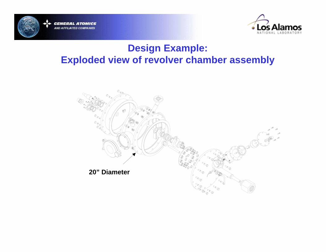
Design Example:Exploded view of revolver chamber assembly
20” Diameter
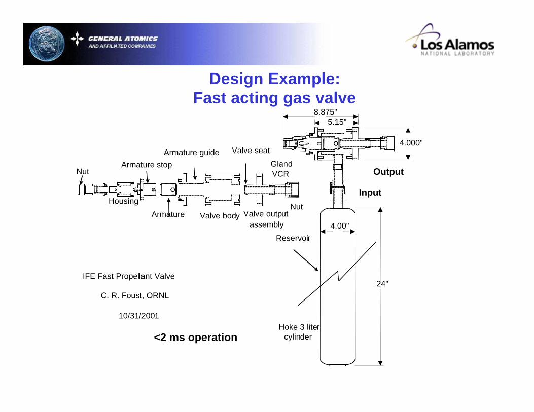
Design Example:Fast acting gas valve
24"
4.00"
Output
Input
4.000"
IFE Fast Propellant Valve
C. R. Foust, ORNL
10/31/2001Hoke 3 liter
cylinder
VCRGland
Valve outputassembly
Valve seat
Valve body
Armature guide
Armature
Armature stop
Housing
Nut
Reservoir
Nut
8.875"5.15"
<2 ms operation

A change from the PDR is use of pulsed laser illuminationof position verification cameras
Beam Collimator
Anamorphic Prisms 6X Beam
Expander
Laser Diode4 ns Pulse
Area Scan Camera
(Gated ICCD not required)

FY 2001 | FY 2002 | FY 2003 | FY 2004 | FY 2005 | FY 2006 | FY2007
Simplified Target Fab/Injection 5-Year Plan
Injection Accuracy and Tracking
Data, Anal. and Modeling
Target Fabrication
Studies, R&D, Proof of Principle
NRL Target Physics
Prel.TargetDesigns
Target Analysis(Continuing)
TargetBaselineDesign(NRL)
Engineering Prototype Development
Upgrade to Cryo Cryo
Target InjectionIRE Plant Design
IRE Plant Design
CY01 CY02 CY03 CY04 CY05Final DesignProcurement & Fabrication
Assembly and InitialShakedownAcquire Data, ModifyEquipment to Optimize ResultsDoc. Results/Support IREDecisionConceptual Design of InjectorUpgrades (Cryo & High-TempEquipment)Implement Cryo Upgrades

Significant drag occurs even at low chamber gas densities
F C r vD D t= ( . )0 5 2 2πρ
Coefficient of Drag vs Velocity
0.001.002.003.004.005.006.007.008.009.00
0 200 400 600 800 1000 1200
Velocity (m/s)
500 mTorr50 mTorr5 mTorr0.5 mTorr
At lower (<~ 5 mTorr) pressures CD does not change with density.Therefore the drag force increases linearly with density. For low density (< 50 mTorr), the drag coefficient is cut in half as speedincreases from 200 to 400 m/s. Therefore, FD ~CDv2 increases linearly ratherthan quadratically with speed.
Range of interest
*Pressures at standard temperature
Based on DSMC drag force calculations
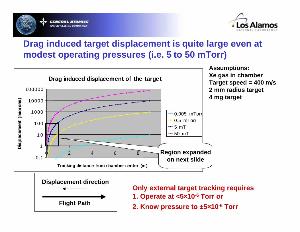
Drag induced target displacement is quite large even atmodest operating pressures (i.e. 5 to 50 mTorr)
Assumptions:Xe gas in chamberTarget speed = 400 m/s 2 mm radius target 4 mg target
Only external target tracking requires1. Operate at <5××××10-6 Torr or
2. Know pressure to ±5××××10-6 Torr
Drag induced displacement of the target
0.1
1
1 0
100
1000
10000
100000
0 2 4 6 8 1 0
Tracking distance from chamber center (m)
0.005 mTorr0.5 mTorr5 mT50 mT
Flight Path
Displacement direction
Region expandedon next slide

In-chamber tracking is required for higher pressure ops
Conclusion:Need to track to within 1 m if pressure is known to 0.5 mTorr
Drag-induced displacement of the target
1.0
10.0
100.0
0 0.2 0.4 0.6 0.8 1
Tracking distance from chamber center (m)
Dis
plac
emen
t (m
icro
ns)
0.5 mTorr5 mT50 mT

Gas density fluctuations affect required tracking distance
5 mTorr 10 mTorr 50 mTorr5% Fluctuations 1.3 m (3.2 ms) 0.95 m (2.4 ms) 0.46 m (1.2 ms)10% Fluctuations 0.95 m (2.4 ms) 0.66 m (1.65 ms) 0.33 m (0.83 ms)50% Fluctuations 0.42 m (1.1 ms) 0.30 m (0.75 ms) 0.15 m (0.38 ms)
Assumptions:Shot to shot chamber gas density is unknown to ± fluctuation value2 mm radius, 4 mg target moving 400 m/sTarget velocity is well measuredXe gas drag ±10 micron affect on target position
Even 5% fluctuations of 5 mTorr chamber gasrequires tracking to within 1.3 m of chamber center

Windspeed fluctuations affect required tracking distance
Normalized wind speed 5 mTorr 10 mTorr 50 mTorr5% Fluctuations 1.3 m (3.2 ms) 0.95 m (2.4 ms) 0.46 m (1.2 ms)10% Fluctuations 0.95 m (2.4 ms) 0.66 m (1.65 ms) 0.33 m (0.83 ms)50% Fluctuations 0.42 m (1.1 ms) 0.30 m (0.75 ms) 0.15 m (0.38 ms)
Assumptions:2 mm radius, 4 mg target moving 400 m/s Shot to shot normalized wind speed is unknown to ± fluctuation valueTarget velocity is well measuredUnknown wind affect on drag has ±10 micron affect on target position Drag force is proportional to target velocity relative to chamber gas
(true for <~50 mTorr gas and velocity < ~400 m/s)
Same table applies as for gas density variations Normalized wind speed is chamber gas speed divided by target speed
Resultant velocity, force or displacement components are independent
Force or displacement due to target velocity
Force or displacement due to wind speed
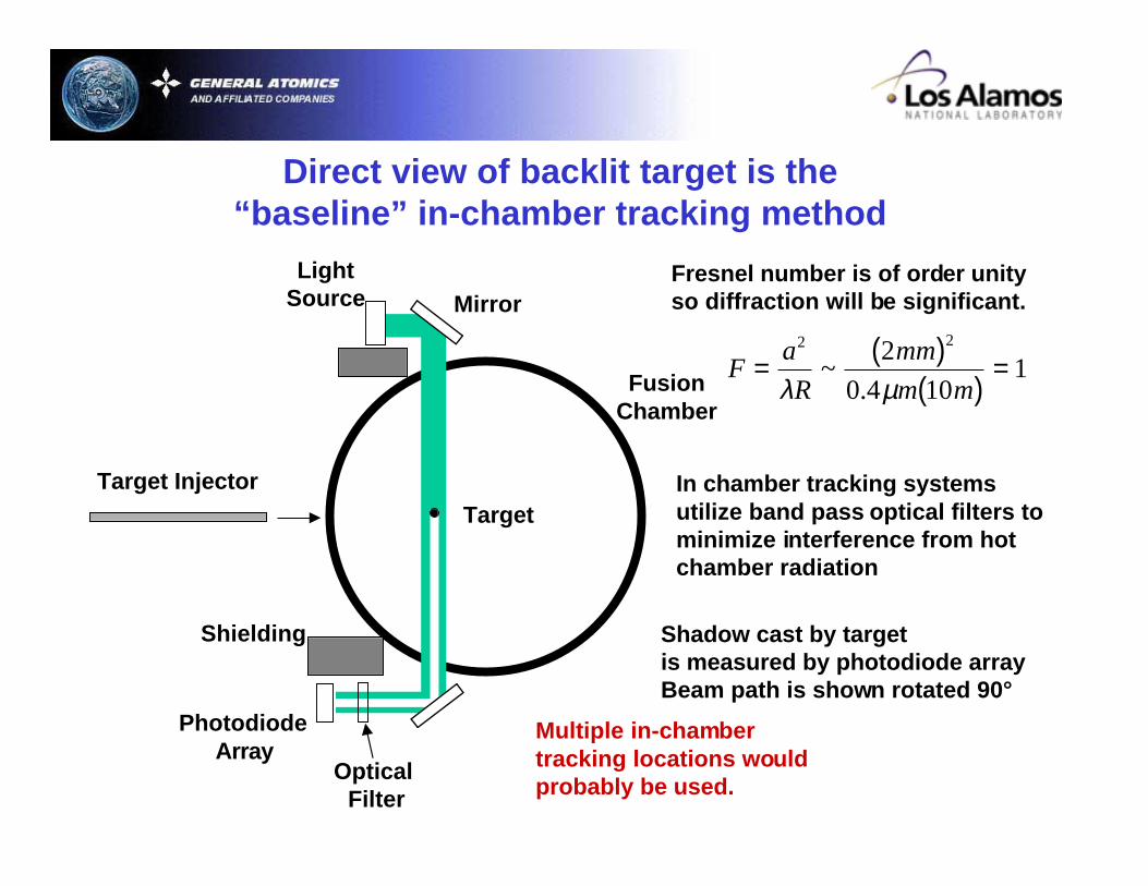
Direct view of backlit target is the“baseline” in-chamber tracking method
Mirror
LightSource
Photodiode Array
Shielding
FusionChamber
Multiple in-chambertracking locations wouldprobably be used.
Shadow cast by targetis measured by photodiode arrayBeam path is shown rotated 90°
Optical Filter
In chamber tracking systemsutilize band pass optical filters tominimize interference from hotchamber radiation
Target
Target Injector
Fa
R
mm
m m= ( )
( )=
2 22
0 4 101
λ µ~
.
Fresnel number is of order unityso diffraction will be significant.

An interferometric tracking method may also be possible
Laser
BeamSplitter
InterferencePattern
OpticalFilter
TargetInjector
OpticalFibers
PhotodiodeDetector
Detect target passing interference fringes in thechamber. Complementary to external tracking.Dr. Ilya AgurokSBIR-Physcical Optics Corporation, Torrance,CA
Target
Fusion Chamber
Conventional ExternalTracking Detectors
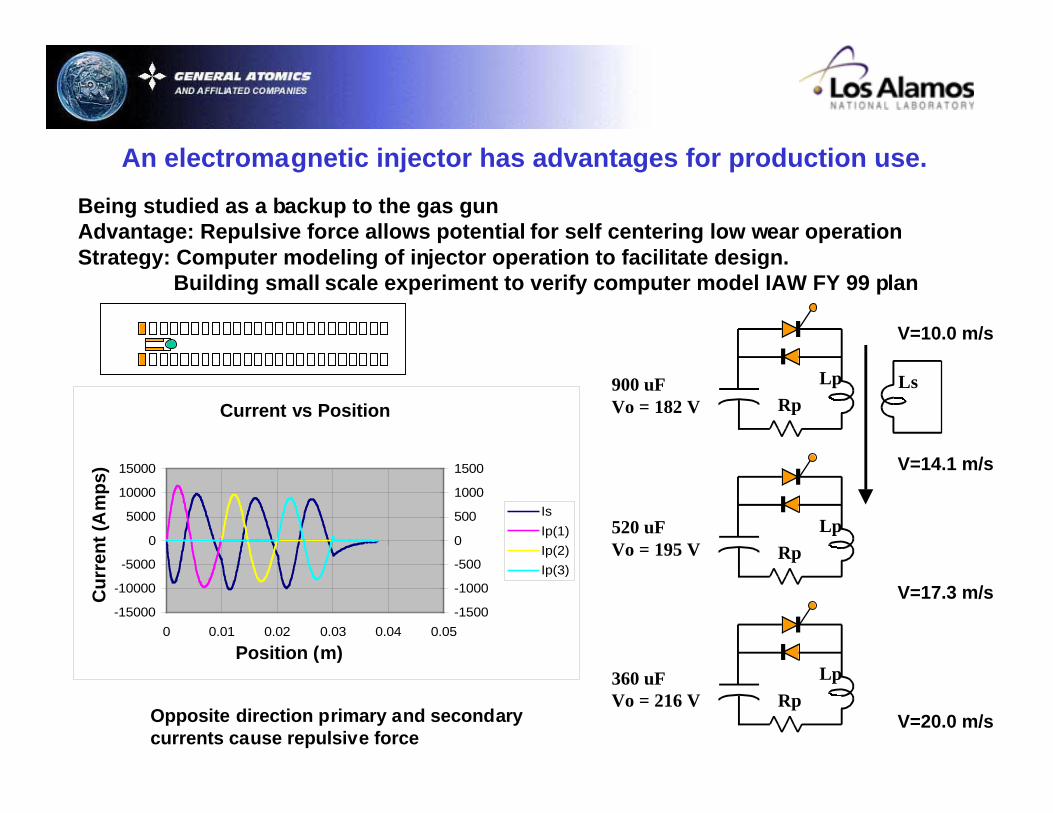
An electromagnetic injector has advantages for production use.
Being studied as a backup to the gas gunAdvantage: Repulsive force allows potential for self centering low wear operationStrategy: Computer modeling of injector operation to facilitate design.
Building small scale experiment to verify computer model IAW FY 99 plan
V=10.0 m/s
900 uFVo = 182 V
Lp
RpLs
520 uFVo = 195 V
Lp
Rp
360 uFVo = 216 V
Lp
Rp
V=14.1 m/s
V=17.3 m/s
V=20.0 m/s
Current vs Position(1-3)
-15000
-10000
-5000
0
5000
10000
15000
0 0.01 0.02 0.03 0.04 0.05
Position (m)
Cu
rren
t (A
mp
s)
-1500
-1000
-500
0
500
1000
1500
Is
Ip(1)
Ip(2)
Ip(3)
Opposite direction primary and secondarycurrents cause repulsive force
Current vs Position
Cu
rren
t (A
mp
s)
Position (m)

Summary and Conclusions
Injection and tracking experimental design • Project is proceeding on schedule• The target injection and tracking system final design review is this Friday
In-chamber tracking• External tracking of direct drive targets requires pressure known to ~10-5 Torr• 0.5 mTorr Xe pressure uncertainty requires tracking to 1 m from center (Direct Drive)• A fractional change in normalized wind speed affects target trajectory same as an equivalent change in gas density• “Baseline” in-chamber tracking is modified external method
• Mirrors and optical filters will be added• Stand-off distance is greater implying more diffraction
• Interferometric target tracking is being investigated
Electromagnetic injector• A non-contacting electromagnetic injector is being modeled as a backup to the gas gun