1-2 design considerations - fema.gov considerations 1- aggressor tactics run the gamut: moving...
TRANSCRIPT
design considerations 1
1-1design considerations
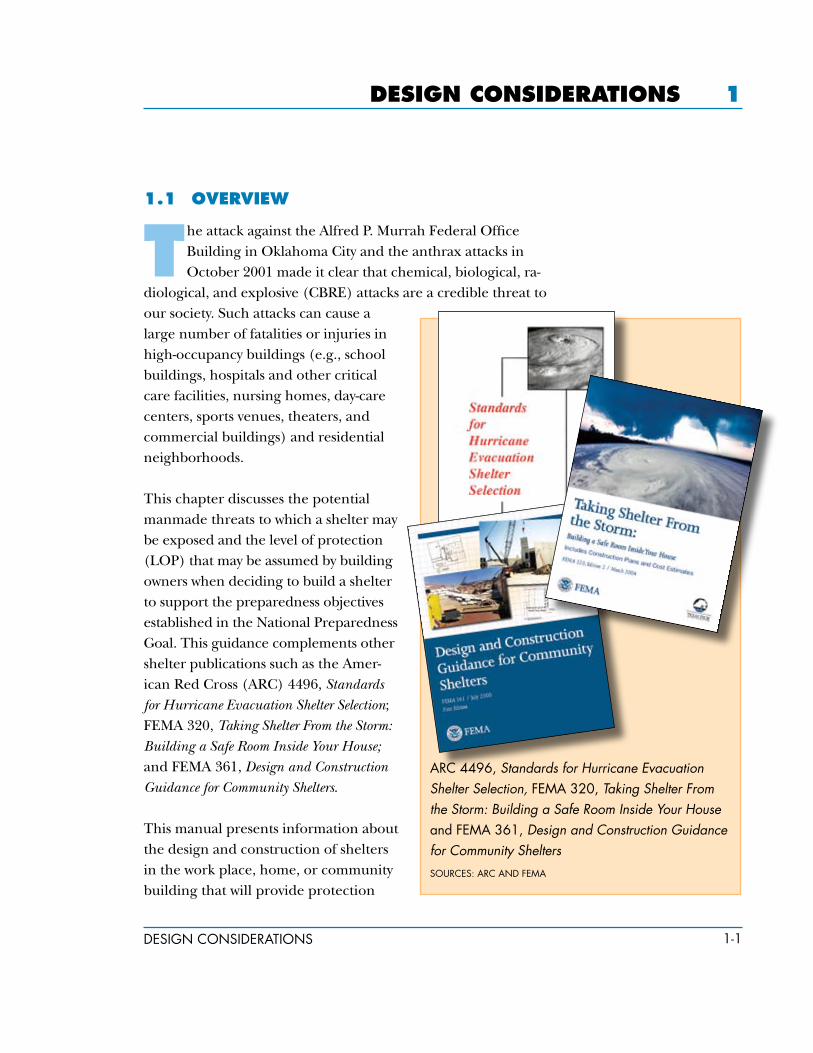
arc 4496, Standards for Hurricane Evacuation Shelter Selection, FeMa 320, Taking Shelter From the Storm: Building a Safe Room Inside Your House and FeMa 361, Design and Construction Guidance for Community Shelters
sources: arc and FeMa
1.1 oVerVieW
the attack against the Alfred P. Murrah Federal Office Building in Oklahoma City and the anthrax attacks in October 2001 made it clear that chemical, biological, ra-
diological, and explosive (CBRE) attacks are a credible threat to our society. Such attacks can cause a large number of fatalities or injuries in high-occupancy buildings (e.g., school buildings, hospitals and other critical care facilities, nursing homes, day-care centers, sports venues, theaters, and commercial buildings) and residential neighborhoods.
This chapter discusses the potential manmade threats to which a shelter may be exposed and the level of protection (LOP) that may be assumed by building owners when deciding to build a shelter to support the preparedness objectives established in the National Preparedness Goal. This guidance complements other shelter publications such as the Amer-ican Red Cross (ARC) 4496, Standards for Hurricane Evacuation Shelter Selection; FEMA 320, Taking Shelter From the Storm: Building a Safe Room Inside Your House; and FEMA 361, Design and Construction Guidance for Community Shelters.
This manual presents information about the design and construction of shelters in the work place, home, or community building that will provide protection

1-2 design considerations
in response to the manmade CBRE threats as defined in the National Response Plan (NRP) and the National Planning Sce-narios. As published in the National Preparedness Guidance (April 2005), the Federal interagency community developed 15 plan-ning scenarios (the National Planning Scenarios or Scenarios) for use in national, Federal, state, and local homeland security preparedness activities. The National Planning Scenarios are planning tools and are representative of the range of potential terrorist attacks and natural disasters and the related impacts that face our nation. The scenarios establish the range of response re-quirements to facilitate preparedness planning.
The National Planning Scenarios describe the potential scope and magnitude of plausible major events that require coordina-tion among various jurisdictions and levels of government and communities.
Scenario 1: Nuclear Detonation – 10-Kiloton Improvised Nuclear Device
Scenario 2: Biological Attack – Aerosol Anthrax
Scenario 3: Biological Disease Outbreak – Pandemic Influenza
Scenario 4: Biological Attack – Plague
Scenario 5: Chemical Attack – Blister Agent
Scenario 6: Chemical Attack – Toxic Industrial Chemicals
Scenario 7: Chemical Attack – Nerve Agent
Scenario 8: Chemical Attack – Chlorine Tank Explosion
Scenario 9: Natural Disaster – Major Earthquake
Scenario 10: Natural Disaster – Major Hurricane
Scenario 11: Radiological Attack – Radiological Dispersal Devices
Scenario 12: Explosives Attack – Bombing Using Improvised Explosive Device
Scenario 13: Biological Attack – Food Contamination

1-3design considerations
Scenario 14: Biological Attack – Foreign Animal Disease (Foot and Mouth Disease)
Scenario 15: Cyber Attack
Manmade threats include threats of terrorism, technological accidents, assassinations, kidnappings, hijackings, and cyber at-tacks (computer-based), and the use of CBRE weapons. High-risk targets include military and civilian government facilities, interna-tional airports, large cities, and high-profile landmarks. Terrorists might also target large public gatherings, water and food sup-plies, utilities, and corporate centers. Further, they are capable of spreading fear by sending explosives or chemical and biological agents through the mail.
This chapter also considers shelter design concepts that relate to the type of shelter being designed and where it may be located. It discusses how shelter use (either single or multiple) may affect the type of shelter selected and the location of that shelter on a particular site. The chapter describes key operations zones in and around a shelter that need to be taken into consideration as a means to provide safe ingress and egress and medical assistance to victims of a manmade event (terrorist attack or technological accident). The decision to enter a shelter is made by the senior management staff based on notification of a credible threat or as a result of an actual disaster. The National Incident Management System (NIMS) and the Catastrophic Incident Supplement (CIS) to the NRP established the procedures to respond to and recover from a CBRE event. Section 4.2 discusses the plan’s alerting and notification, and response and recovery processes. The objective of this chapter is to provide a broad vision on how a shelter should be designed to protect against catastrophic events.
The decision to design and construct a shelter can be based on a single factor or on a collection of factors. Single factors are often related to the potential for loss of life or injury (e.g., a hospital that cannot move patients housed in an intensive care unit decides to build a shelter, or shelters, within the hospital; a school

1-4 design considerations
decides not to chance fate and constructs a shelter). A collection of factors could include the type of hazard event, probability of event occurrence, severity of the event, probable single and ag-gregate annual event deaths, shelter costs, and results of computer models that evaluate the benefits and costs of the shelter project.
1.2 PotentiaL tHreats
Rather than identify a specific threat, this document provides general guidance that will address different types of building construction and the reasonable mitigative measures to provide a secure shelter. However, it is important for building owners and design professionals to understand the potential threats to which buildings may be exposed. This section provides an overview of manmade threats.
The term “threat” is typically used to describe the design criteria for manmade disasters (technological accident) or terrorism. Identifying the threats for manmade threats can be a difficult task. Because they are different from other natural hazards such as earthquakes, floods, and hurricanes, manmade threats are diffi-cult to predict. Many years of historical and quantitative data, and probabilities associated with the cycle, duration, and magnitude of natural hazards exist. The fact that data for manmade threats are scarce and that the magnitude and recurrence of terrorist attacks are almost unpredictable makes the determination of a particular threat for any specific site or building difficult and largely subjec-tive. Such asymmetrical threats do not exclusively target buildings and may employ diversionary tactics to actually direct occupants to a primary attack instrument.
With any manmade threat, it is important to determine who has the intent to cause harm. The aggressors seek publicity for their cause, monetary gain (in some instances), or political gain through their actions. These actions can include injuring or killing people; destroying or damaging facilities, property, equipment, or re-sources; or stealing equipment, material, or information.

1-�design considerations
Aggressor tactics run the gamut: moving vehicle bombs; sta-tionary vehicle bombs; bombs delivered by persons (suicide bombers); exterior attacks (thrown objects like rocks, Molotov cocktails, hand grenades, or hand-placed bombs); stand-off weapons attacks (rocket propelled grenades, light antitank weapons, etc.); ballistic attacks (small arms and high power rifles); covert entries (gaining entry by false credentials or cir-cumventing security with or without weapons); mail bombs (delivered to individuals); supply bombs (larger bombs processed through shipping departments); airborne contamination (CBR agents used to contaminate the air supply of a building); and waterborne contamination (CBR agents injected into the water supply). This section focuses on explosive threats, chemical agents, biological warfare agents, and radiological attacks.
1.2.1 explosive threats
The explosive threat is particularly insidious, because all of the in-gredients required to assemble an improvised explosive device are readily available at a variety of farm and hardware stores. The in-tensity of the explosive detonation is limited by the expertise of the person assembling the device and the means of delivery. Although the weight of the explosive depends on the means of transporta-tion and delivery, the origin of the threat depends primarily on the access available to the perpetrator. Operational security pro-cedures will define the areas within or around a building at which a device may be located, undetected by the building facilities staff. These security procedures include screening of vehicles, inspection of delivered parcels, and vetting hand carried bags. The extent to which this inspection is carried out will determine the size of an ex-plosive device that may evade detection. Despite the most vigilant attempts, however, it is unrealistic to expect complete success in preventing a small threat from evading detection. Nevertheless, it is unlikely that a large threat may be brought into a building. As a result, a parcel sized device may be introduced into publicly acces-sible lobbies, garages, loading docks, cafeterias, or retail spaces and it must be assumed that a smaller explosive device may be brought anywhere into the building.

1-6 design considerations
Although operational security measures can drastically limit the size of the explosive device that could be introduced onto a building site, there is no means of limiting the size of the ex-plosive that could be contained within a vehicle traveling on the surrounding streets or roadways.
Explosives weigh approximately 100 pounds per cubic foot and, as a result, the maximum credible threat corresponds to the weight of explosives that can be packaged in a variety of containers or vehicles. The Department of Defense (DoD) developed a chart to help indicate the weight of explosives and deflagrating materials that may reasonably fit within a variety of containers and vehicles (see Table 1-1). The table also indicates the safe evacuation dis-tances for occupants of conventional unreinforced buildings, based on their ability to withstand severe damage or resist col-lapse. Similarly, Table 1-1 indicates the safe evacuation distance for pedestrians exposed to explosive effects based on the greater of fragment throw distance or glass breakage/falling glass hazard distance. Because a pipe bomb, suicide belt/vest, backpack, and briefcase/suitcase bomb are specifically designed to throw frag-ments, protection from these devices may require greater safe evacuation distances than an equal weight of explosives trans-ported in a vehicle. Table 1-2 shows safe evacuation distances for liquefied petroleum gas (LPG) threats.

1-�design considerations
Table 1-1: Safe Evacuation Distances from Explosive Threats
Threat DescriptionExplosives Mass* (TNT equivalent)
Building Evacuation Distance**
Outdoor Evacuation Distance***
High
Exp
losiv
es (T
NT E
quiv
alen
t)
Pipe Bomb � lbs 2.3 kg
�0 ft 21 m
8�0 ft 2�9 m
suicide Belt 10 lbs 4.� kg
90 ft 2� m
1,080 ft 330 m
suicide Vest 20 lbs 9 kg
110 ft 34 m
1,360 ft 41� m
Briefcase/suitcase Bomb
�0 lbs 23 kg
1�0 ft 46 m
1,8�0 ft �64 m
compact sedan
�00 lbs 22� kg
320 ft 98 m
1,�00 ft 4�� m
sedan 1,000 lbs 4�4 kg
400 ft 122 m
1,��0 ft �34 m
Passenger/cargo Van
4,000 lbs 1,814 kg
640 ft 19� m
2,��0 ft 838 m
small Moving Van/ delivery truck
10,000 lbs 4,�36 kg
860 ft 263 m
3,��0 ft 1,143 m
Moving Van/Water truck
30,000 lbs 13,608 kg
1,240 ft 3�� m
6,�00 ft 1,982 m
semi-trailer 60,000 lbs 2�,216 kg
1,��0 ft 4�� m
�,000 ft 2,134 m
* Based on the maximum amount of material that could reasonably fit into a container or vehicle. Variations are possible.
** governed by the ability of an unreinforced building to withstand severe damage or collapse.
*** governed by the greater of fragment throw distance or glass breakage/falling glass hazard distance. these distances can be reduced for personnel wearing ballistic protection. note that the pipe bombs, suicide belts/vests, and briefcase/suitcase bombs are assumed to have a fragmentation characteristic that requires greater stand-off distances than an equal amount of explosives in a vehicle.

1-8 design considerations
The Bureau of Alcohol, Tobacco, Firearms, and Explosives (ATF) report on Incidents, Casualties and Property Damage for all states for 2002 lists 553 actual bombing incidents, 32 of which were prema-ture explosions, injuring 80 people, killing 13, and causing over $5 million in damages. Nearly half of the events were against build-ings and nearly a quarter were against vehicles.
Table 1-2: Safe Evacuation Distances from LPG Threats
Threat Description LPG Mass/Volume Fireball Diameter*
Safe Distance**
Lique
fied
Petro
leum
Gas
(LPG
- Bu
tane
or P
ropa
ne)
small LPg tank
20 lbs/� gal 9 kg/19 l
40 ft 12 m
160 ft 48 m
Large LPg tank
100 lbs/2� gal 4� kg/9� l
69 ft 21 m
2�6 ft 84 m
commercial/residential LPg tank
2,000 lbs/�00 gal 90� kg/1,893 l
184 ft �6 m
�36 ft 224 m
small LPg truck
8,000 lbs/2,000 gal 3,630 kg/�,��0 l
292 ft 89 m
1,168 ft 3�6 m
semi-tanker LPg
40,000 lbs/10,000 gal
18,144 kg/3�,8�0 l
499 ft 1�2 m
1,996 ft 608 m
* assuming efficient mixing of the flammable gas with ambient air.
** determined by u.s. firefighting practices wherein safe distances are approximately four times the flame height. note that an LPg tank filled with high explosives would require a significantly greater stand-off distance than if it were filled with LPg.

1-9design considerations
Only two domestic terrorist bombings involved the use of large quantities of High Energy explosive materials. (For more informa-tion on High Energy explosives, see FEMA 426, Reference Manual to Mitigate Potential Terrorist Attacks Against Buildings, Chapter 4.) Although these events represent the largest explosions that have occurred to date, they do not accurately represent the actual domestic explosive threat. The 1995 explosion that collapsed portions of the Murrah Federal Office Building in Oklahoma City contained 4,800 pounds of ammonium nitrate and fuel oil (ANFO) and the 1993 explosion within the parking garage be-neath the World Trade Center complex contained 1,200 pounds of urea nitrate.
Every year, approximately 1,000 intentional explosive detonations are reported by the Federal Bureau of Investigation (FBI) Bomb Data Center. As implied by the FBI statistics, the majority of the domestic events contain significantly smaller weights of Low En-ergy explosives. (For more information on Low Energy explosives, see FEMA 426, Chapter 4.) Figure 1-1 illustrates the breakdown of domestic terrorist events from 1980 to 2001. The vast majority of the 294 terrorist incidents, 55 suspected terrorist incidents, or 133 prevented terrorist incidents, involved explosives and 75 percent of these events occurred in the 1980s. The explosive that was used in the 1996 pipe bomb attack at the Olympics in Atlanta, Georgia, consisted of smokeless powder and was preceded by a warning that was called in 23 minutes before the detonation.

1-10 design considerations
Although the majority of these explosions targeted residential properties and vehicles, 63 took place in educational facilities, causing a total of $68,500 in property damage. By contrast, other than the attack against the Murrah Federal Office Building, no explosive devices were detonated at a Federal government owned facility, and only nine were detonated at local/state government facilities. Nearly 80 percent of the people known to be involved in bombing incidents were “young offenders,” and less than ½ per-cent of the perpetrators were identified as members of terrorist groups. Vandalism was the motivation in 53 percent of the known intentional and accidental bombing incidents, and the timing of the attacks was fairly uniformly distributed throughout the day.
Figure 1-1 terrorism by event 1980 through 2001
source: FBi terrorisM 2000/2001 PuBLication #308

1-11design considerations
Nevertheless, the protective design of structures focuses on the ef-fects of High Energy explosives and relates the different mixtures to an equivalent weight of trinitrotoluene (TNT).
1.2.2 cBr attacks
Like explosive threats, CBR threats may be delivered externally or internally to the building. External ground-based threats may be released at a stand-off distance from the building or may be delivered directly through an air intake or other opening. Inte-rior threats may be delivered to accessible areas such as the lobby, mailroom, or loading dock, or they may be released into a secure area such as a primary egress route. There may not be an official or obvious warning prior to a CBR event. Although official warn-ings should always be heeded, the best defense may be to be alert to signs of a release.
There are three potential methods of attacks in terms of CBR:
m A large exterior release originating some distance away from the building (includes delivery by aircraft)
m A small localized exterior release at an air intake or other opening in the exterior envelope of the building
m A small interior release in a publicly accessible area, a major egress route, or other vulnerable area (e.g., elevator lobby, mail room, delivery, receiving and shipping, etc.)
Chapter 4 provides additional guidance on emergency manage-ment considerations that may have an impact on siting or design of a shelter.
1.2.2.1ChemicalAgents.Toxic chemical agents can present air-borne hazards when dispersed as gases, vapors, or solid or liquid aerosols. Generally, chemical agents produce immediate effects, unlike biological or radiological agents. In most cases, toxic chemical agents can be detected by the senses, although a few are
1-12 design considerations
odorless. Their effects occur mainly through inhalation, although they can also cause injury to the eyes and skin.
1.2.2.2 BiologicalWarfareAgents.Biological warfare agents are or-ganisms or toxins that can kill or incapacitate people and livestock, and destroy crops. The three basic groups of biological agents that would likely be used as weapons are bacteria, viruses, and toxins.
m Bacteria. Bacteria are small free-living organisms that reproduce by simple division and are easy to grow. The diseases they produce often respond to treatment with antibiotics.
m Viruses. Viruses are organisms that require living cells in which to reproduce and are intimately dependent upon the body they infect. The diseases they produce generally do not respond to antibiotics; however, antiviral drugs are sometimes effective.
m Toxins. Toxins are poisonous substances found in, and extracted from, living plants, animals, or microorganisms; some toxins can be produced or altered by chemical means. Some toxins can be treated with specific antitoxins and selected drugs.
Most biological agents are difficult to grow and maintain. Many break down quickly when exposed to sunlight and other environ-mental factors, while others such as anthrax spores are very long lived. They can be dispersed by spraying them in the air or by infected animals that carry the disease, as well through food and water contamination:
m Aerosols. Biological agents are dispersed into the air, forming a fine mist that may drift for miles. Inhaling the agent may cause disease in people or animals.
m Animals. Some diseases are spread by insects and animals, such as fleas, flies, mosquitoes, and mice. Deliberately spreading diseases through livestock is also referred to as agroterrorism.

1-13design considerations
m Foodandwatercontamination. Some pathogenic organisms and toxins may persist in food and water supplies. Most microbes can be killed, and toxins deactivated, by cooking food and boiling water.
Person-to-person spread of a few infectious agents is also possible. Humans have been the source of infection for smallpox, plague, and the Lassa viruses.
anthrax spores formulated as a white powder were mailed to individuals in the Federal government and media in the fall of 2001. Postal sorting machines and the opening of letters dispersed the spores as aerosols. several deaths resulted. the effect was to disrupt mail service and to cause a widespread fear of handling delivered mail among the public.
Figure 1-2 sample anthrax letter
source: FBi terrorisM 2000/2001 PuBLication #308
1.2.2.3RadiologicalAttacks.Shelters described in this manual do not address the severe and various effects generated by nuclear events, including blinding light, intense heat (thermal radiation), initial nuclear radiation, blast, fires started by the heat pulse, and secondary fires caused by the destruction. Protection against these severe effects of a nuclear explosion is not considered in this manual.
Terrorist use of a radiological dispersion device (RDD), often called ”dirty nuke” or “dirty bomb,” is considered far more likely than use of a nuclear device. These radiological weapons are a combination of conventional explosives and radioactive material designed to scatter dangerous and sublethal amounts of radio-active material over a general area. Such radiological weapons

1-14 design considerations
appeal to terrorists because they require very little technical knowledge to build and deploy compared to that of a nuclear device. Also, these radioactive materials, used widely in medicine, agriculture, industry, and research, are much more readily avail-able and easy to obtain compared to weapons grade uranium or plutonium. Figure 1-3 shows the number of incidents of radioac-tive materials smuggling from 1993 to 2003.
Figure 1-3 radioactive materials smuggling
source: internationaL atoMic energy agency
There is no way of knowing how much warning time there would be before an attack by a terrorist using a radiological weapon. A surprise attack remains a possibility.

1-1�design considerations
1.3 LeVeLs of Protection
Currently, there are only two Federal standards that have been promulgated for Federal facilities that define LOPs for manmade threats: the Interagency Security Committee (ISC) Design Criteria and the DoD Minimum Antiterrorism Standards, UFC 4-010-01. Both standards address blast primarily through the use of stand-off distance and ensuring walls and glazing blast pressures are strengthened to withstand the blast shock wave. Both standards address CBR agents primarily through the use of filtration, emer-gency shutdown of mechanical and electrical systems, and mass notification to building occupants.
Until the building, mechanical, electrical, and life safety codes are promulgated for manmade events, the ISC building standards pro-vide a reasonable approach to selecting a level of protection for a shelter for CBR agents.
1.3.1 Blast Levels of Protection
The level of protection in response to blast loading defines the extent of damage and debris that may be sustained in response to the resulting blast pressures and impulses. (For more information on blast pressure impulses, see FEMA 426, Chapter 4.) The levels of protection are generally defined in the terms of performance. Fundamental to the discussion of levels of protection is the notion of repairable damage. Repair is typically assumed to be within days to weeks and the structure requires partial evacuation during re-pairs. Table 1-3 provides a synopsis of the ISC blast standards.

1-16 design considerations
Table 1-3: Correlation of ISC Levels of Protection and Incident Pressure to Damage and Injury
Level of Protection Potential Structural Damage Potential Glazing Hazards
Minimum and Low
the facility or protected space will sustain a high level of damage without progressive collapse. casualties will occur and assets will be damaged. Building components, including structural members, will require replacement, or the facility may be completely unrepairable, requiring demolition and replacement.
For Minimum Protection, there are no restrictions on the type of glazing used.
For Low Protection, there is no requirement to design windows for specific blast pressure loads. However, the use of glazing materials and designs that minimize the risks is encouraged.
glazing cracks and window system fails cata-strophically. Fragments enter space, impacting a vertical witness panel at a distance of no more than 3 m (10 ft) from the window at a height greater than 0.6 m (2 ft) above the floor.
Medium
Moderate damage, repairable. the facility or protected space will sustain a significant degree of damage, but the structure will be reusable. some casualties may occur and assets may be damaged. Building elements other than major structural members may require replacement.
For Medium and High Protection, design up to the specified load as directed by the risk assessment. Window systems design (glazing, frames, anchorage to supporting walls, etc.) on the exterior façade should be balanced to mitigate the hazardous effects of flying glazing following an explosive event. the walls, anchorage, and window framing should fully develop the capacity of the glazing material selected.
glazing cracks. Fragments enter space and land on the floor and impact a vertical witness panel at a distance of no more than 3 m (10 ft) from the window at a height greater than 0.6 m (2 ft) above the floor.
High
Minor damage, repairable. the facility or protected space may globally sustain minor damage with local significant damage possible. occupants may incur some injury, and assets receive minor damage.
For Medium and High Protection, design up to the specified load as directed by the risk assessment. Window systems design (glazing, frames, anchorage to supporting walls, etc.) on the exterior façade should be balanced to mitigate the hazardous effects of flying glazing following an explosive event. the walls, anchorage, and window framing should fully develop the capacity of the glazing material selected.
glazing cracks. Fragments enter space and land on the floor no farther than 3 m (10 ft) from the window.

1-1�design considerations
1.3.2 cBr Levels of Protection
Protection against airborne chemical, biological, and radiological (CBR) agents or contaminants is typically achieved by using par-ticulate and adsorption filters, and personal protective equipment (PPE). Many different types of filters are available for CBR re-leases. Filter efficiency (e.g., how well the filter captures the toxic material) varies based on the filter type (e.g., activated or impreg-nated charcoal) and the specific toxic material. No single filter can protect against all CBR materials; therefore, it is important to verify which CBR materials a filter protects against.
There are three levels of protection that range from filtration with pressurization (Class 1), filtration with little or no pressurization (Class 2), and passive protection (Class 3). Class 1 protection is for a large-scale release over an extended period of time and would apply to mission essential government and commercial buildings that must remain operational 24 hours a day/7 days a week. Class 2 protection is for a terrorist attack or technological accident with little or no warning and is characterized as a short duration small scale release. Class 3 is typically applicable to an industrial acci-dent that results in a short duration release. These three levels of protection are discussed in greater detail in Chapter 3. Table 1-4 provides a synopsis of the ISC CBR protection standards.
the cBr levels of protection included in this section are consistent with the department of Homeland security (dHs) Working group on radiological dispersal device Preparedness and the Health Physics society’s (HPs’s) scientific and Public issues committee reports:
“sheltering is 10-80% effective in reducing dose depending upon the duration of exposure, building design and ventilation. if there is a passing plume of radioactivity, sheltering may be preferable to evacuation. When sheltering, ventilation should be turned off to reduce influx of outside air. sheltering may not be appropriate if doses are projected to be very high or long in duration.”
“sheltering is likely to be more protective than evacuation in responding to a radiological terrorist event. therefore, the HPs recommends that sheltering be the preferred protective action. the Protective action guidance (Pag) for sheltering is the same as the existing evacuation Pag, i.e., 10 msv (1 rem), with the minimum level for initiation being the same as the existing Pag, i.e., 1 msv (100 mrem).”

1-18 design considerations
Table 1-4: ISC CBR Levels of Protection
Level of Protection
For Biological/Radiological
Contaminants
For Chemical/
Radiological Additional Considerations Class
Low use minimum efficiency reporting value (MerV) 13 filter or functional equivalent.
none none 3
Medium
use high-efficiency particulate air (HePa) filter or functional equivalent.
use gas absorber for outside air.
design for future detection technology
stairway pressurization system should maintain positive pressure in stairways for occupant refuge, safe evacuation, and access by firefighters. the entry of smoke and hazardous gases into stairways must be minimized.
Locate utility systems at least 1� m (�0 ft) from loading docks, front entrances, and parking areas.
2
High
use HePa filter or functional equivalent.
use gas absorber for outside air and return air.
design for future detection technology
stairway pressurization system should maintain positive pressure in stairways for occupant refuge, safe evacuation, and access by firefighters. the entry of smoke and hazardous gases into stairways must be minimized.
Locate utility systems at least 1� m (�0 ft) from loading docks, front entrances, and parking areas.
1, 2

1-19design considerations
1.4 sHeLter tYPes
A CBRE shelter can be designed as a standalone or internal shelter to be used solely as a shelter or to have multiple purposes, uses, or occupancies. This section provides a series of definitions that can be useful when deciding to build a new shelter or up-grade an existing shelter.
1.4.1 standalone shelters
A standalone shelter is considered a separate building (i.e., not within or attached to any other building) that is designed and con-structed to withstand the range of natural and manmade hazards. This type of shelter has the following characteristics:
m It may be sited away from potential debris hazards.
m It will be structurally and mechanically separate from any building and therefore not vulnerable to being weakened if part of an adjacent structure collapses or if a CBRE event occurs in the adjacent building.
m It does not need to be integrated into an existing building design.
A shelter for CBRE protection may be as simple as an interior residential room to the traditional public shelter able to support several hundred people. The number of persons taking refuge in a shelter will typically be more than 12 and could be up to several hundred or more.
1.4.2 internal shelters
An internal shelter is a specially designed and constructed room or area within or attached to a larger building that is designed and constructed to be structurally independent of the larger building and to withstand the range of natural and manmade hazards. It shows the following characteristics:

1-20 design considerations
m It is partially shielded by the surrounding building and may not experience the full force of the blast. (Note that any protection provided by the surrounding building should not be considered in the shelter design.)
m It is designed to be within a new building and may be located in an area of the building that the building occupants can reach quickly, easily, and without having to go outside, such as a data center, conference room, gymnasium, or cafeteria.
m It may reduce the shelter cost because it is typically part of a planned renovation or building project.
1.4.3 shelter categories
A standalone or internal shelter may serve as a shelter only, or it may have multiple uses (e.g., a multi-use shelter at a school could also function as a classroom, lunchroom, or laboratory; a multi-use shelter intended to serve a manufactured housing community or single-family-home subdivision could also function as a com-munity center). The decision to design and construct a single-use or a multi-use shelter will likely be made by the prospective client or the owner of the shelter. To help the designer respond to non-engineering and non-architectural needs of shelter owners, this section discusses different shelter categories and usages. Table 1-5 provides a summary of the commercial shelter categories.

1-21design considerations
Table 1-5: Commercial Shelter Categories
Shelter Considerations In-Ground Single-Use Multi-Use Community
Level of ProtectionBlast – Medium
cBr – class 3
Blast – Low
cBr – class 3
all all
Expected Capacity 1-100 1-10 1-100 100-1,000
Location
Basement or sub-basement area without windows and semi-hardened walls and ceiling
interior space without windows and semi-hardened walls and ceiling
conference room
data center
Bathroom
stairwell
elevator core
school
church
Mall
government Building
Special Considerations
difficult to site/build in high water table and rocky areas
annual or semi-annual inspection and rotation of supplies
May need multiple areas in large buildings and commercial office space; plan and exercises to prevent overcrowding
Plan for multi-lingual, elderly, non-ambulatory, and special needs populations
• Life safety nFPa 101 and �000 guidance
• ada compliance
nFP = national Fire Protection associationada = americans with disabilities act
m In-groundshelters. The in-ground shelters referred to in this manual are built below ground inside a building and therefore can be entered directly from within the building. Other types of in-ground shelters are available that are designed to be installed outside a building and entering one of these exterior in-ground shelters would require leaving the building.

1-22 design considerations
m Single-useshelters. Single-use shelters are used only in the event of a hazard event. One advantage of single-use shelters is a potentially simplified design that may be readily accepted by the authority having local jurisdiction. These shelters typically have simplified electrical and mechanical systems because they are not required to provide normal daily accommodations for people. Single-use shelters are always ready for occupants and will not be cluttered with furnishings and storage items, which is a concern with multi-use shelters. Simplified, single-use shelters may have a lower total cost of construction than multi-use shelters.
The cost of building a single-use shelter is much higher than the additional cost of including shelter protection in a multi-use room. Existing maintenance plans will usually consider multi-use rooms, but single-use shelters can be expected to require an additional annual maintenance cost.
m Multi-useshelters. The ability to use a shelter for more than one purpose often makes a multi-use standalone or internal shelter appealing to a shelter owner or operator. Multi-use shelters also allow immediate return on investment for owners/operators; the shelter space is used for daily business when the shelter is not being used during a hazard event. Hospitals, assisted living facilities, and special needs centers would benefit from multi-use internal shelters, such as hardened intensive care units or surgical suites. Internal multi-use shelters in these types of facilities allow optimization of space while providing near-absolute protection with easy access for non-ambulatory persons. In new buildings being designed and constructed, recent FEMA-sponsored projects have indicated that the construction cost of hardening a small area or room in a building is 10 to 25 percent higher than the construction cost for a non-hardened version of the same area or room.
m Communitysheltersatneighborhoodsandorpublicfacilities. Community shelters are intended to provide protection for the residents of neighborhoods and are

1-23design considerations
typically located at schools and other similar institutions; they are identified, categorized, and labeled by the American Red Cross (see ARC 4496).
1.5 siting
One of the most important elements in designing a shelter is its location or siting. In inspecting areas of existing buildings that are used as shelter areas, research has found that owners may over-look the safest area of a building, while the safety of a hallway or other shelter areas may be overestimated. Evaluating shelter areas in an existing building or determining the best areas for new ones is invaluable for saving lives when a disaster strikes.
The location of a shelter on a building site is an important part of the design process for shelters. The shelter location on the site and capacity should consider how many occupants work in the building, as well as how many non-occupants may take refuge in the nearest shelter available. At the site and building level, the shelter location analysis should include evaluation of potential CBRE effects.
When deciding to build a shelter, a preliminary evaluation may be performed by a design professional or by a potential shelter owner, property owner, emergency manager, building mainte-nance person, or other interested party provided he or she has a basic knowledge of building sciences and can understand building design plans and specifications. AlthoughthethreatofdamagefromCBREeventsmaybethepredominantfocusoftheevalua-tion,additionalthreatsmayexistfromtornado,hurricane,flood,andseismicevents;therefore,theevaluationshouldassessthethreatatthesite. Prior to the design and construction of a shelter, a design professional should perform a more thorough assessment in order to confirm or, as necessary, modify the findings of a pre-liminary assessment.
An entire building or a section of a building may be designated as a potential shelter area. To perform an assessment of an existing

1-24 design considerations
structure or a new structure to be used as a shelter, the building owner or designers may use the Building Vulnerability Assessment Checklist included in FEMA 426, Reference Manual to Mitigate Po-tential Terrorist Attacks Against Buildings; FEMA 452, A How-To Guide to Mitigate Potential Terrorist Attacks Against Buildings for the assess-ment of CBRE events; and FEMA 433, Using HAZUS-MH for Risk Assessment for the assessment of major natural hazards.
If an existing building is selected for use as a shelter, the Building Vulnerability Assessment Checklist will help the user identify major vulnerabilities and/or the best shelter areas within the building to place the shelter. The checklist consists of questions pertaining to structural, nonstructural, and mechanical character-istics of the area being considered. The questions are designed to identify structural, nonstructural, and mechanical vulnerabilities to CBRE hazards based on typical failure mechanisms. Structural, nonstructural, and mechanical deficiencies may be remedied with retrofit designs; however, depending on the type and degree of de-ficiency, the evaluation may indicate that the existing structure is unsuitable for use as a shelter area. A detailed analysis should con-sider if a portion of a particular building can be used as shelter or whether that portion is structurally independent of the rest of the building. It should also determine if the location is easily acces-sible, contains the required square footage, and has good ingress and egress elements.
The shelter should be located such that all persons designated to take refuge may reach the shelter with minimal travel time. Shel-ters located at one end of a building or one end of a community, office complex, or school may be difficult for some users at a site to reach in a timely fashion. Routes to the shelter should be easily accessible and well marked. Exit routes from the shelter should be in a direction away from the threat. Hazard signs should be lo-cated following Crime Prevention Through Environmental Design (CPTED) principles of natural access control, natural surveillance, and territoriality and illustrated in Figure 1-4.

1-2�design considerations
m Naturalaccesscontrol(controlsaccess).Guides people entering and leaving a space through the placement of entrances, exits, fences, landscaping, and lighting. Access control can decrease opportunities for terrorist activity by denying access to potential targets and creating a perception of risk for would-be terrorists.
m Naturalsurveillance(increasesvisibility).The placement of physical features, activities, and people in a way that maximizes visibility. A potential criminal is less likely to attempt an act of terrorism if he or she is at risk of being observed. At the same time, we are likely to feel safer when we can see and be seen.
Figure 1-4 example of shelter marking on building, floor plan, and exterior exits to rally points

1-26 design considerations
m Territoriality(promotesasenseofownership). The use of physical attributes that express ownership such as fences, signage, landscaping, lighting, pavement designs, etc. Defined property lines and clear distinctions between private and public spaces are examples of the application of territoriality. Territoriality can be seen in gateways into a community or neighborhood.
Shelters should also be located outside areas known to be flood-prone, including areas within the 100-year floodplain. Shelters in flood-prone areas will be susceptible to damage from hydrostatic and hydrodynamic forces associated with rising flood waters. Damage may also be caused by debris floating in the water. Most importantly, flooding of occupied shelters may well result in inju-ries or deaths. Furthermore, shelters located in flood-prone areas, but properly elevated above the 100-year flood elevation, could become isolated if access routes were flooded. As a result, shelter occupants could be injured and no emergency services would be available.
Where possible, the shelter should be located away from large objects and multi-story buildings. Light towers, antennas, satel-lite dishes, and roof-mounted mechanical equipment may be toppled or become airborne during blast, hurricane, tornado, or earthquake events. Multi-story buildings adjacent to a shelter may be damaged or may fail structurally due to natural or manmade hazards. When these types of objects or structures fail, they may damage the shelter by collapsing onto it or impacting it. The impact forces associated with these objects are well outside the design parameters of any building code.
There are several possible locations in a building or a house for a shelter. Perhaps the most convenient and safest is below ground level, in a basement. If the building or house does not have a basement, an in-ground shelter can be installed beneath a concrete slab-on-grade foundation or a concrete garage floor (typically would be used as a single-use shelter). Basement

1-2�design considerations
shelters and in-ground shelters provide the greatest degree of protection against missiles and falling debris.
Another alternative shelter location is an interior room on the first floor of a building or house. Closets, bathrooms, and small storage rooms offer the advantage of having a function other than providing occasional storm protection. Typically, these rooms have only one door and no windows, which make them well-suited for conversion to a shelter. Bathrooms have the added advantage of a water supply and toilet.
Regardless of where in a building or house a shelter is built, the walls and ceiling of the shelter must be built so that they will protect the occupants from missiles and falling debris, and so that they will remain standing if the building or house is severely damaged by extreme winds. If sections of the building or house walls are used as shelter walls, those sections must be separated from the structure of the building or house. This is true regard-less of whether interior or exterior walls of the building or house are used as shelter walls.
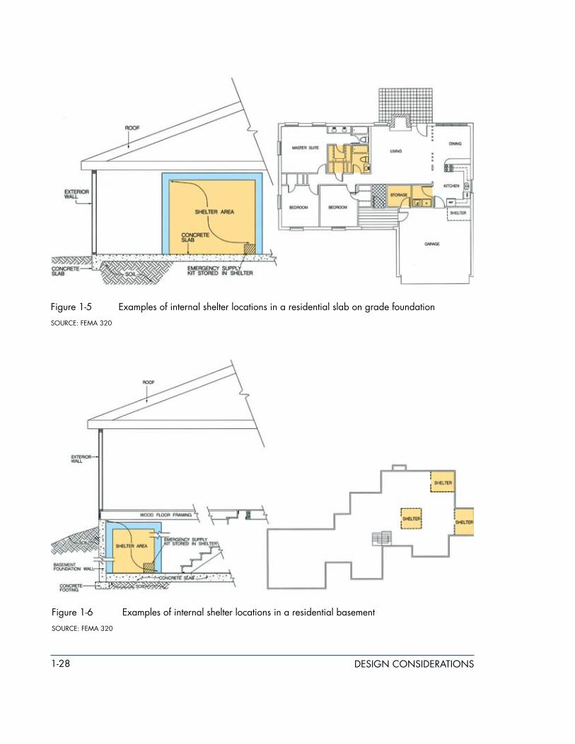
Typical floor plans of possible locations for shelters in a home are highlighted in yellow in Figures 1-5 and 1-6. These are not floor plans developed specifically for houses with shelters, but they show how shelters can be added without changes to the layout of rooms.
1-28 design considerations
Figure 1-� examples of internal shelter locations in a residential slab on grade foundation
source: FeMa 320
Figure 1-6 examples of internal shelter locations in a residential basement
source: FeMa 320
1-29design considerations
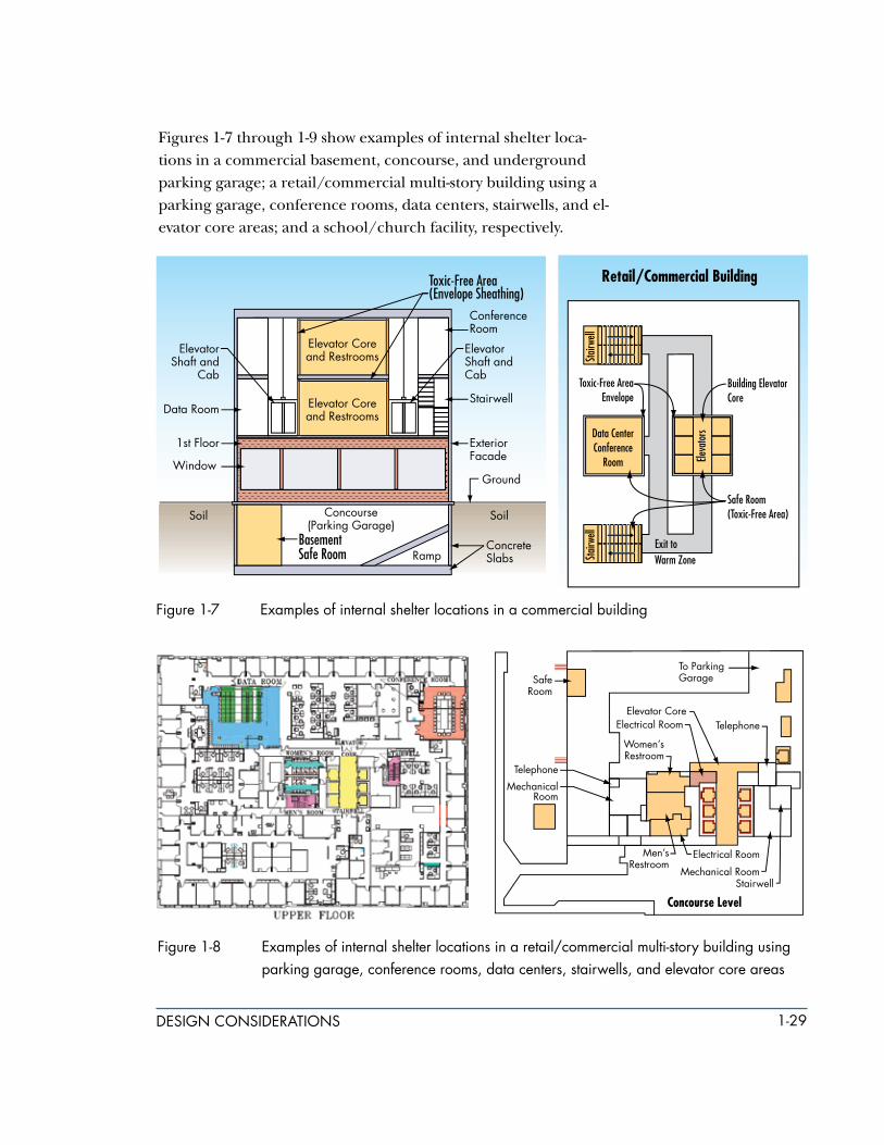
Figures 1-7 through 1-9 show examples of internal shelter loca-tions in a commercial basement, concourse, and underground parking garage; a retail/commercial multi-story building using a parking garage, conference rooms, data centers, stairwells, and el-evator core areas; and a school/church facility, respectively.
Figure 1-� examples of internal shelter locations in a commercial building
Figure 1-8 examples of internal shelter locations in a retail/commercial multi-story building using parking garage, conference rooms, data centers, stairwells, and elevator core areas

1-30 design considerations
Currently, standalone shelters are relatively rare and most remaining shelters are remnants of the Cold War era that were de-signed for nuclear weapons protection as “fallout shelters.” These shelters were called “dedicated shelters” to make a clear differen-tiation from dual use shelters (normal facilities in the community that had enhanced radiation protection). Dedicated shelters were built with very high levels of protection and did not have peace time functional compromises. Siting of standalone shelters for nuclear protection has typically been underground, as tunnels, caves, or buried structures. The mass of the geological materials absorbed the blast energy and provided radiation shielding.
Many of the siting and design principles developed by the Office of Civil Defense in FEMA TR-29, Architect & Engineer Activities in Shelter Development; FEMA RR-7, Civil Defense Shelters A State of the Art Assessment 1986; and FEMA TR-87, Standards for Fallout Shelters are still applicable.
Figure 1-9 examples of internal shelter locations in a school/church facility
-
-
-

1-31design considerations
For a standalone shelter, many sites will be constrained or site lim-ited for underground, and an aboveground structure may be the only feasible alternative. For these sites, the siting considerations include:
m Outside the floodplain
m Separation distance between buildings and structures to prevent progressive collapse or impact from collapsing elements
m Separation from major transportation features (road, rail)
m Access to redundant power and communications capabilities
1.6 occuPancY duration, toxic-free area (tfa) fLoor sPace, and VentiLation requirements
Occupancy duration (also known as button-up time) is the length of time that people will be in the shelter with the doors closed and in the protected environment. This period of time is determined by the building owner or local authorities and can range from several hours to several days. For off-site industrial accidents, the occupancy duration is usually less than 24 hours; occupancy durations longer than 24 hours are generally restricted to war-time. Occupancy duration stops when the doors to the shelter are opened. It influences the floor area requirements and the amount of consumable and waste storage. Generally, occupancy duration will not significantly affect the performance of the col-lective protection system.
a. Less Than 24 Hours. An occupancy duration of less than 24 hours does not require sleeping areas. The occupant load will generally be a net 1.86 m2/person (20 square feet/person), depending upon the classification of occupancy. The classification of occupancy, as stated in NFPA 101, may require a higher or lower occupant
cBr collective Protection shelter Basics
m occupancy duration
m toxic-free area (tFa) Floor space
m Ventilation requirements
1-32 design considerations
loading depending upon the building classification. The occupant loading will be coordinated with the authority having jurisdiction.
b. More Than 24 Hours. An occupancy duration greater than 24 hours requires sleeping areas. The minimum floor area, with the use of single size beds, is approximately 5.6 m2/person (60 square feet/person). With the use of bunked beds, the minimum floor area is approximately 2.8 m2/person (30 square feet/person).
The total required TFA floor space is determined from the oc-cupancy duration, the number of people sheltered, and the required floor area per person. Generally, large open areas such as common areas, multi-purpose areas, gymnasiums, etc., provide the most efficient floor area for protecting a large number of per-sonnel. The TFA envelope should include bathroom facilities and, if possible, kitchen facilities.
Although the planned response to CBR events may be to tem-porarily deactivate the ventilation systems, both single- and multi-use shelters must include ventilation systems capable of providing the minimum number of air changes required by the building code for the shelter’s occupancy classification. This will provide a flushing capability once the CBR hazard has passed and facilitate use of the shelter for non-CBR events. For single-use shelters, 15 cubic feet per person per minute is the minimum air exchange recommended; this recommendation is based on guid-ance outlined in the International Mechanical Code (IMC). For multi-use shelters, the design of mechanical ventilation systems is recommended to accommodate the air exchange requirements for the occupancy classification of the normal use of the shelter area. Although the ventilation system may be overwhelmed in a rare event when the area is used as a shelter, air exchange will still take place. The designer should still confirm with the local building official that the ventilation system may be designed for the normal-use occupancy. In the event the community where the shelter is to be located has not adopted a model building and/or mechanical code, the requirements of the most recent edition of the International Building Code (IBC) are recommended.

1-33design considerations
1.7 Human factors criteria
Human factors criteria for the natural and manmade hazard shel-ters build on existing guidance provided in this chapter and in FEMA 320 and 361. Although existing documents do not address all the human factors involved in the design of CBRE shelters, they provide the basis for the criteria summarized in this chapter. These criteria are detailed in the following sections.
1.7.1 square footage/occupancy requirements
The duration of occupancy of a shelter will vary, depending on the intended event for which the shelter has been designed. Oc-cupancy duration is an important factor that influences many aspects of the design process.
The recommended minimums are 5 square feet per person for tornado shelters and 10 square feet per person for hurricane shelters. The shelter designer should be aware of the occupancy requirements of the building code governing the construction of the shelter. The occupancy loads in the building codes have histor-ically been developed for life safety considerations. Most building codes will require the maximum occupancy of the shelter area to be clearly posted. Multi-use occupancy classifications are pro-vided in the IBC; NFPA 101, Life Safety Code; NFPA 5000, Building Construction and Safety Code; and state and local building codes. Conflicts may arise between the code-specified occupancy classifi-cations for normal use and the occupancy needed for sheltering. For example, according to the IBC and NFPA 101 and 5000, the occupancy classification for educational use is 20 square feet per person; however, the recommendation for a tornado shelter is 5 square feet per person. Without proper signage and posted oc-cupancy requirements, using an area in a school as a shelter can create a potential conflict regarding the allowed number of per-sons in the shelter. If both the normal maximum occupancy and the shelter maximum occupancy are posted, and the shelter oc-cupancy is not based on a minimum less than the recommended 5 square feet per person, the shelter design should be acceptable to the building official. The IBC, NFPA 101 and 5000, and the

1-34 design considerations
model building codes all have provisions that allow occupancies as concentrated as 5 square feet per person. The American So-ciety of Heating, Refrigeration, and Air-Conditioning Engineers (ASHRAE) recommends that a minimum head room of 6.5 feet and a minimum of 65 cubic feet of net volume be provided per shelter occupant. Net volume shall be determined using the net area calculated for the space.
ASHRAE Ventilation Standard 62-1981, Ventilation for Smoking-Per-mitted Areas defines minimum outdoor air supply rates for various types of occupancy. These rates have been arrived at through a consensus of experts working in the field. A minimum rate of 5 cfm per person for sedentary activity and normal diet holds the carbon dioxide (CO2) level in a space at 0.25 percent under steady state conditions. Although normal healthy people tolerate 0.5 percent CO2 without undesirable symptoms and nuclear subma-rines sometimes operate with 1 percent CO2 in the atmosphere, a level of 0.25 percent provides a safety factor for increased activity, unusual occupancy load, or reduced ventilation. The ASHRAE Handbook 1982 Applications Environmental Control for Survival states that carbon dioxide concentration should not ex-ceed 3 percent by volume and preferably should be maintained below 0.5 percent. For a sedentary man, 3 cfm per person of fresh air would maintain a CO2 concentration of 0.5 percent.
1.7.1.1TornadoorShort-termShelterSquareFootageRecom-mendations. Historical data indicate that tornado shelters will typically have a maximum occupancy time of 2 hours. Because the occupancy time is so short, many items that are needed for the comfort of occupants for longer durations (in hurricane shelters) are not recommended for a tornado shelter. FEMA 361, Section 8.2 recommends a minimum of 5 square feet per person for tor-nado shelters. However, other circumstances and human factors may require the shelter to accommodate persons who require more than 5 square feet. Square footage recommendations for persons with special needs are presented below; these recommen-dations are the same as those provided in the FEMA 1999 National Performance Criteria for Tornado Shelters:

1-3�design considerations
m 5 square feet per person adults standing
m 6 square feet per person adults seated
m 5 square feet per person children (under the age of 10)
m 10 square feet per person wheelchair users
m 30 square feet per person bedridden persons
1.7.1.2HurricaneorLong-termShelterSquareFootageRecom-mendations.Historical data indicate that hurricane shelters will typically have a maximum occupancy time of 36 hours. For this reason, the occupants of a hurricane shelter need more space and comforts than the occupants of a tornado shelter. FEMA 361, Sec-tion 8.2 recommends a minimum of 10 square feet per person for hurricane shelters (for a hurricane event only; an event expected to last less than 36 hours). The American Red Cross 4496 publica-tion recommends the following minimum floor areas (Note: the ARC square footage criteria are based on long-term use of the shelter [i.e., use of the shelter both as a refuge area during the event and as a recovery center after the event]):
m 20 square feet per person for a short-term stay (i.e., a few days)
m 40 square feet per person for a long-term stay (i.e., days to weeks)
Again, the designer should be aware that there can be conflicts between the occupancy rating for the intended normal use of the shelter and the occupancy required for sheltering. This oc-cupancy conflict can directly affect exit (egress) requirements for the shelter.
1.7.2 distance/travel time and accessibility
The shelter designer should consider the time required for all oc-cupants of a building or facility to reach the shelter. The National Weather Service (NWS) has made great strides in predicting tor-nadoes and hurricanes and providing warnings that allow time to seek shelter; it has now expanded the service to include all hazards.

1-36 design considerations
As part of the NIMS, for tornadoes, the time span is often short between the NWS warning and the onset of the tornado. Figure 1-10 shows a sample NWS current watches, warnings, statements, and advisories summary. This manual recommends that a tornado shelter be designed and located in such a way that the following ac-cess criteria are met: all potential users of the shelter should be able to reach it within 5 minutes, and the shelter doors should be secured within 10 minutes. For hurricane shelters, these restrictions do not apply, because warnings are issued much earlier, allowing more time for preparation. A CBRE event may have warning such as the Irish Republican Army gave to London police and residents, or no warning as happened with the events of 9/11, and anthrax and sarin releases in October 2001 and the Tokyo subway, respectively.
Figure 1-10 national Weather service forecast and warnings
source: nWs
Travel time may be especially important when shelter users have disabilities that impair their mobility. Those with special needs may require assistance from others to reach the shelter; wheel-chair users may require a particular route that accommodates the wheelchair. The designer must consider these factors in order to

1-3�design considerations
provide the shortest possible access time and most accessible route for all potential shelter occupants.
Access is an important element of shelter design. If obstructions exist along the travel route, or if the shelter is cluttered with non-essential equipment and storage items, access to the shelter will be impeded. It is essential that the path remain unencumbered to allow orderly access to the shelter. Hindering access in any way can lead to chaos and panic. For example, at a community shelter built to serve a residential neighborhood, parking at the shelter site may complicate access to the shelter; at a non-residential shelter, such as at a manufacturing plant, mechanical equipment can impede access.
Unstable or poorly secured building elements could potentially block access if a collapse occurs that creates debris piles along the access route or at entrances. A likely scenario is an overhead canopy or large overhang that lacks the capacity to withstand blast effects collapses over the entranceway. The inclusion of these elements should be seriously considered when designing ac-cess points in shelters.
1.7.3 americans with disabilities act (ada)
The needs of persons with disabilities requiring shelter space should be considered. The appropriate access for persons with disabilities must be provided in accordance with all Federal, state, and local ADA requirements and ordinances. If the minimum requirements dictate only one ADA-compliant access point for the shelter, the design professional should consider providing a second ADA-compliant access point for use in the event that the primary access point is blocked or inoperable. Additional guidance for compliance with the ADA can be found in many pri-vately produced publications.
The design professional can ensure that the operations plan developed for the shelter adheres to requirements of the ADA by assisting the owner/operator of the shelter in the devel-opment of the plan. All shelters should be managed with an

1-38 design considerations
operations and maintenance plan. Developing a sound opera-tions plan is extremely important if compliance with ADA at the shelter site requires the use of lifts, elevators, ramps, or other considerations for shelters that are not directly accessible to non-ambulatory persons.
1.7.4 special needs
The use of the shelter also needs to be considered in the design.Occupancy classifications, life safety code, and ADA requirements may dictate the design of such elements as door opening sizes and number of doors, but use of the shelter by hospitals, nursing homes, assisted living facilities, and other special needs groups may affect access requirements to the shelter. For example, basic requirements are outlined in the IBC and NFPA 101 and 5000 regarding the provision of uninterruptible power supplies for life support equipment (e.g., oxygen) for patients in hospitals and other health care facilities. NFPA 99, Standard for Healthcare Facilities, specifies details on subjects such as the type, class, and duration of power supplies necessary for critical life support equipment. In addition, it also details the design, arrangement, and configuration of medical gas piping systems, alarms, and net-works.
In addition, strict requirements concerning issues such as egress, emergency lighting, and detection-alarm-communication systems are presented in Chapter 10 of the IBC and in NFPA 101, 2006 Edition, Chapters 18 and 19, for health care occupancies. The egress requirements for travel distances, door widths, and locking devices on doors for health care occupancies are more restrictive than those for an assembly occupancy classification in non-health care facilities based on the model building codes for non-health care facilities. Additional requirements also exist for health care facilities that address automatic fire doors, maximum allowable room sizes, and maximum allowable distances to egress points. The combination of all these requirements could lead to the con-struction of multiple small shelters in a health care facility rather than one large shelter.

1-39design considerations
1.8 otHer design considerations
Emergency lighting and power, as well as a backup power source, need to be included in the design of multi-use shelters. Route marking and wayfinding, and signage also should be included.
1.8.1 Lighting
For the regular (i.e., non-shelter) use of multi-use shelters, lighting, including emergency lighting for assembly occupancies, is required by all model building codes. Emergency lighting is recommended for community shelters. A backup power source for lighting is essential during a disaster because the main power source is often disrupted. A battery-powered system is recommended as the backup source because it can be located, and fully protected, within the shelter. Flashlights stored in cabi-nets are useful as secondary lighting provisions, but should not be used as the primary backup lighting system.
A reliable lighting system will help calm shelter occupants during a disaster. Failing to provide proper illumination in a shelter may make it difficult for shelter owners/operators to minimize the agitation and stress of the shelter occupants during the event. If the backup power supply for the lighting system is not contained within the shelter, it should be protected with a structure designed to the same criteria as the shelter itself. Natural lighting provided by windows and doors is often a local design requirement, but is not required by the IBC for assembly occupancies. The 2003 edi-tion of the IBC and the 2006 edition of NFPA 5000 has additional guidance on egress, lighting, and markings.
1.8.2 emergency Power
Shelters will have different emergency (backup) power needs based upon the length of time that people will stay in the shelters (i.e., shorter duration for tornadoes and longer duration for hur-ricanes). In addition to the essential requirements that must be provided in the design of the shelter, comfort and convenience should be addressed.

1-40 design considerations
For tornado shelters, the most critical use of emergency power is for lighting. Emergency power may also be required in order to meet the ventilation requirements described in Chapter 3 and Section 1.7.1. The user of the shelter should set this requirement for special needs facilities, but most tornado shelters would not require additional emergency power.
For hurricane shelters, emergency power may be required for both lighting and ventilation. This is particularly important for shelters in hospitals and other special needs facilities. Therefore, a backup generator is recommended. Any generator relied on for emergency power should be protected with an enclosure designed to the same criteria as the shelter.
As illustrated in the previous sections, the manmade hazards shelter design criteria require an adjustment to the traditional design process for natural hazard shelters. The shelter location, operation, and life-cycle costs are now significantly coupled to the community, first responders, and government plans and proce-dures for mass casualty response and recovery; Federal and local laws for criminal investigation; and the unique site and building design parameters and level of protection that is desired.
1.8.3 route marking and Wayfinding
Route marking or wayfinding in an emergency situation such as total darkness has historically relied on fire exit lighting. A new technology that is being adopted by many cities is photolumines-cent exit path marking. These photoluminescent self-adhesive signs and tapes are very visible during the day and will glow for up to 8 hours after the light source is removed. These signs have du-rable, permanent, and renewable fluorescence. Figure 1-11 shows sample signs.

1-41design considerations
Figure 1-11 Photoluminescent signs, stair treads, and route marking

1-42 design considerations
1.8.4 signage
The signs should be illuminated, luminescent, and obvious. Key elements of signage include the following.
1.8.4.1CommunityandParkingSignage. It is very important that shelter occupants can reach the shelter quickly and without chaos. Parking is often a problem at community shelters; therefore, a Community Shelter Operations Plan should instruct occupants to proceed to a shelter on foot if time permits. Main pathways should be determined and laid out for the community. Pathways should be marked to direct users to the shelter. Finally, the exterior of the shelter should have a sign that clearly identifies the building as a shelter.
1.8.4.2SignageatSchoolsandPlacesofWork. Signage for shel-ters at schools and places of work should be clearly posted and should direct occupants through the building or from building to building. If the shelter is in a government-funded or public-funded facility, a placard should be placed on the outside of the building designating it an emergency shelter (see Figure 1-12). It is recommended that signage be posted on the outside of all other
Reference Standard 6-1
Photoluminescent exit path markings as required by Local Law 26 of 2004, new york city Building code § 2�-383(b)
this standard is intended to provide minimum requirements for photoluminescent exit path markings that will aid in evacuation from buildings in the event of failure of both the power and back-up power to the lighting and illuminated exit signs. Photoluminescent material is charged by exposure to light and will emit luminance after the activating light source is unavailable. the markings covered by this standard are not designed to provide enough light to illuminate a dark egress path, but rather will provide luminescent signs and outlines of the egress path, stairs, handrails, and obstacles, so that occupants can discern these egress path elements in dark conditions. the markings are generally required to be located at a low location in case of smoke and to be readily seen, such as in a crowd situation. they are in addition to, and not as a substitute for, any other signage required under the Building code, such as electrically illuminated exit signs with electrical back-up power required under § 2�-383(a).

1-43design considerations
types of shelters as well. It is important to note, however, that once a public building has been identified as a shelter, people who live or work in the area around the shelter will expect the shelter to be open during an event. Shelter owners should be aware of this and make it clear that the times when a shelter will be open may be limited. For example, a shelter in an elementary school or com-mercial building may not be accessible at night.
Figure 1-12 shelter signage

1-44 design considerations
1.9 eVacuation considerations
When designing a shelter, evacuation is one of the most impor-tant aspects to save lives. During the attack of the World Trade Center, good and well-marked egress was critical for thousands of people to evacuate the buildings. The same concept is applicable to shelters. Good ingress and egress, along with robustness and re-dundancy of the structural system, is critical for a sound design.
The matter of high-rise evacuation has become vital since Sep-tember 11, 2001, as a result of the fatalities of almost 3,000
building occupants and emergency per-sonnel. Life safety is provided to building occupants by either giving them the op-portunity to evacuate to a safer place or be protected in place.
The National Institute of Standards and Technology (NIST) Final Report of the Na-tional Construction Safety Team on the Collapses of the World Trade Center Towers conducted analysis of the life safety systems and emer-gency response to validate and expand the state of the practice for high-rise buildings. The NIST study was focused on the collapse mechanisms and life safety systems perfor-mance.
As a result of the collapse of the World Trade Center towers, NIST identified three major scenarios that are not considered ad-equately in current design practice:
m Frequent but low severity events (for design of sprinkler system)
m Moderate but less frequent events (for design of compartmentation)
m A maximum credible fire (for design of passive fire protection on the structure)
every building should have an emergency evacuation and shelter-in-place plan that is coordinated with the local community emergency manager. Building stakeholders and tenants should develop the plan with the objective to save lives and property, and to recover and restore the business should an event occur. the nFPa 1600 Standard on Disaster/Emergency Management and Business Continuity Programs publication provides a framework and recommendations for developing a plan. the building owner, property manager, and tenants should work with the local community to develop an evacuation versus shelter-in-place options matrix as shown in table 1-6.

1-4�design considerations
Table 1-6: Evacuation Versus Shelter-in-place Options Matrix
Attack Agent Timeframe and Protection Objective Occupant/Personnel Action
Chemical – Exterior Release immediate - shelter in safe room, minimize duration and concentration exposure
use portable air filtration, wait for first responder extraction
Chemical – Interior Release immediate - don PPe and evacuate, minimize duration and concentration exposure
Move perpendicular to plume direction, seek decontamination and medical treatment
Biological – Exterior Release immediate - shelter in safe room, do not touch agents, use time to advantage to identify safe evacuation route
use portable air filtration, wait for first responder extraction, seek decontamination and medical treatment
Biological – Interior Release immediate - don PPe and evacuate, minimize duration and concentration exposure
seek decontamination and medical treatment
Radiological/Nuclear – Exterior Release
immediate - shelter in safe room, minimize duration and concentration exposure
use portable air filtration, wait for first responder extraction
Radiological/Nuclear – Interior Release
immediate - don PPe and evacuate, minimize duration and concentration exposure
seek decontamination and medical treatment
Explosive Blast - Exterior immediate - shelter in safe room use portable air filtration, wait for first responder extraction
Explosive Blast - Interior immediate - don PPe and evacuate
seek medical treatment

1-46 design considerations
Three methods are followed for the evacuation of buildings. One method consists of evacuating all occupants simultaneously. Alternatively, occupants may be evacuated in phases, where the floor levels closest to the event are evacuated first and then other floor levels are evacuated on an as needed basis. Phased evacua-tion is instituted to permit people on the floor levels closest to the threatening hazard to enter the stairway unobstructed by queues formed by people from all other floors also being in the stairway. Those who are below the emergency usually are encouraged to stay in place until the endangered people from above are already below this floor level.
The concept of occupant relocation to other floors is usually the best course of action for many types of building emergencies. This method normally involves movement of occupants, from the fire floor, the floor above, and floor below to a lower level until the danger passes.
Evacuation involves providing people with the means to exit the building. The egress system involves the following considerations:
Capacity.A sufficient number of exits of adequate width to ac-commodate the building population need to be provided to allow occupants to evacuate safely.
Access.Occupants need to be able to access an exit from wherever the fire is, and in sufficient time prior to the onset of untenable conditions. Alternative exits should be remotely located so that all exits are not simultaneously blocked by a single incident.
ExitDesign. Exits need to be separated from all other portions of the building in order to provide a protected way of travel to the exit discharge. This involves designing to preclude fire and smoke from entering the exit and will usually involve structural stability.
In general, the means of egress system is designed so that oc-cupants travel from the office space along access paths such as corridors or aisles until they reach the exit or a safer place. An
1-4�design considerations
exit is commonly defined as a protected path of travel to the exit discharge (NFPA 101, 2006). The stairways in a high-rise building commonly meet the definition of an exit. In general, the exit is intended to provide a continuous, unobstructed path to the exte-rior or to another area that is considered safe. Most codes require that exits discharge directly to the outside. Some codes, such as NFPA 101, permit up to half of the exits to discharge within the building, given that certain provisions are met.
There is no universally accepted standard on emergency evacu-ation. Design considerations for high-rise buildings relative to these two options involve several aspects, including design of means of egress, the structure, and active fire protection systems (e.g., detection and alarm, suppression, and smoke manage-ment). Many local jurisdictions, through their fire department public education programs, have developed comprehensive and successful evacuation planning models but, unless they are locally adopted, there is no legal mandate to exercise the plans. Seattle, Phoenix, Houston, and Portland, Oregon, are among the cities that have developed comprehensive programs.
The NIST life safety, egress, and emergency response findings provide valuable lessons learned for future shelter evacuation design. Currently, building fire protection is based on a four-level hierarchical strategy comprising alarm and detection, suppression (sprinklers and firefighting), compartmentation, and passive pro-tection of the structure.
m Manual stations and detectors are typically used to activate fire alarms and notify building occupants and emergency services.
m Sprinklers are designed to control small and medium fires and to prevent fire spread beyond the typical water supply design area of about 1,500 square feet.
m Compartmentation mitigates the horizontal spread of more severe but less frequent fires and typically requires fire-rated

1-48 design considerations
partitions for areas of about 12,000 square feet. Active firefighting measures also cover up to about 5,000 square feet to 7,500 square feet.
m Passive protection of the structure seeks to ensure that a maximum credible fire scenario, with sprinklers compromised or overwhelmed and no active firefighting, results in burnout, not overall building collapse. The intent of building codes is also for the building to withstand local structural collapse until occupants can escape and the fire service can complete search and rescue operations.
NIST recommends that building evacuation should be improved to include system designs that facilitate safe and rapid egress, methods for ensuring clear and timely emergency communica-tions to occupants, better occupant preparedness for evacuation during emergencies, and incorporation of appropriate egress technologies. When designing good evacuation systems and routes of ingress and egress, designers should take into account the fol-lowing considerations:
m As stated above, improved building evacuation, including system designs that facilitate safe and rapid egress, methods for ensuring clear and timely emergency communications to occupants, better occupant preparedness for evacuation during emergencies, and incorporation of appropriate egress technologies. Primary and secondary evacuation routes and exits should be designated and clearly marked and well lit. Signs should be posted.
m Improved emergency response, including better access to the buildings and better operations, emergency communications, and command and control in large-scale emergencies.
m Emergency lighting should be installed in case a power outage occurs during an evacuation.

1-49design considerations
Recommendation 18. nist recommends that egress systems should be designed: (1) to maximize remoteness of egress components (i.e., stairs, elevators, exits) without negatively impacting the average travel distance; (2) to maintain their functional integrity and survivability under foreseeable building-specific or large-scale emergencies; and (3) with consistent layouts, standard signage, and guidance so that systems become intuitive and obvious to building occupants during evacuations.
Recommendation 16. nist recommends that public agencies, non-profit organizations concerned with building and fire safety, and building owners and managers should develop and carry out public education campaigns, jointly and on a nationwide scale, to improve building occupants’ preparedness for evacuation in case of building emergencies. 16Recommendation 17. nist recommends that tall buildings should be designed to accommodate timely full building evacuation of occupants due to building-specific or large-scale emergencies such as widespread power outages, major earthquakes, tornadoes, hurricanes without sufficient advanced warning, fires, accidental explosions, and terrorist attacks. Building size, population, function, and iconic status should be taken into account in designing the egress system. stairwell and exit capacity should be adequate to accommodate counterflow due to emergency access by responders.
17
18Recommendation 19. nist recommends that building owners, managers, and emergency responders develop a joint plan and take steps to ensure that accurate emergency information is communicated in a timely manner to enhance the situational awareness of building occupants and emergency responders affected by an event. this should be accomplished through better coordination of information among different emergency responder groups, efficient sharing of that information among building occupants and emergency responders, more robust design of emergency public address systems, improved emergency responder communication systems, and use of the emergency Broadcast system (now known as the integrated Public alert and Warning system) and community emergency alert networks.
19
Recommendation 21. nist recommends the installation of fire-protected and structurally hardened elevators to improve emergency response activities in tall buildings by providing timely emergency access to responders and allowing evacuation of mobility-impaired building occupants. such elevators should be installed for exclusive use by emergency responders during emergencies. in tall buildings, consideration also should be given to installing such elevators for use by all occupants.
21

1-�0 design considerations
m Evacuation routes and emergency exits should be:
m wide enough to accommodate the number of evacuating personnel.
m clear and unobstructed at all times.
m unlikely to expose evacuating personnel to additional hazards.
m Evacuation routes should be evaluated by a professional.
It is also important to designate assembly areas and a means of obtaining an accurate account of personnel after a site evacuation. Designate areas where personnel should gather after evacuating (see Section 1.10). A head count should be taken after the evacuation. The names and last known locations of personnel not accounted for should be determined and given to the Emergency Op-erations Coordinator (EOC). (Confusion in the assembly areas can lead to unnecessary and dan-gerous search and rescue operations.) A method for accounting for non-employees (e.g., suppliers and customers) should also be established.
In addition, procedures should be established for further evacu-ation in case the incident expands. This may consist of sending employees home by normal means or providing them with trans-portation to an off-site location.
1.10 KeY oPerations Zones
Key operations zones refer to the shelter site surrounding areas and entry and exit control points that need to be taken into con-sideration when designing a shelter.
For catastrophic incidents depicted in the planning scenarios related to the National Response Plan - Catastrophic Incident Supplement (NRP-CIS), decontamination involves several
the 2006 editions of nFPa 101, Life Safety Code and nFPa �000, Building Construction and Safety Code addressed the issue of counter-flow between first responders and descending occupants. the new provisions mandate a minimum stair width of �6 inches (1,420 mm) when a stair is designed to handle an aggregate or accumulated of 2,000 or more occupants. Previous criteria required 44 inches (1,120 mm) minimum.

1-�1design considerations
related and sequential activities. Chief among these are (1) immediate (or gross) decontamination of persons exposed to toxic/hazardous substances; (2) continual decontamina-tion of first responders so that they can perform their essential functions; (3) decontamination of animals in service to first responders; (4) continual decontamination of response equipment and vehicles; (5) secondary, or definitive, decon-tamination of victims at medical treatment facilities to enable medical treatment and protect the facility environment; (6) de-contamination of facilities (public infrastructure, business and residential structures); and (7) environmental (outdoor) decon-tamination supporting recovery and remediation.
1.10.1 containment Zones
There are three zones of containment after an event:
m Hot Zone (the area where the agent or contamination is in high concentration and high exposure, typically an ellipse or cone extending downwind from the release)
m Warm Zone (the area where the agent or contamination is in low concentration or minimal exposure, typically a half circle in the above wind direction)
m Cold Zone (those areas outside of the Hot and Warm zones that have not been exposed to the agent or contamination)
The three zones and staging areas are shown in Figure 1-13.

1-�2 design considerations
Figure 1-13 operations Zones, casualty collection Point (ccP), and safe refuge area (sra)
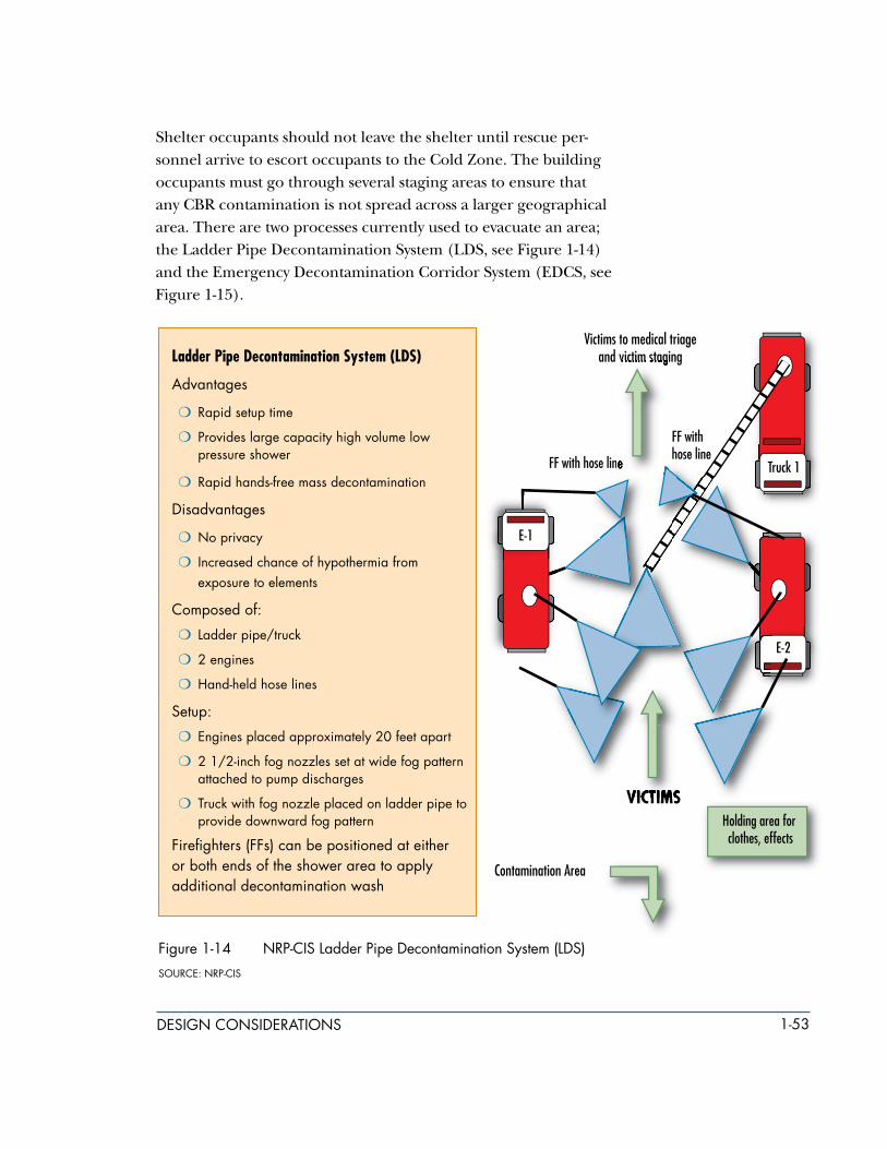
1-�3design considerations
Ladder Pipe Decontamination System (LDS)
advantages
m rapid setup time
m Provides large capacity high volume low pressure shower
m rapid hands-free mass decontamination
disadvantages
m no privacy
m increased chance of hypothermia from exposure to elements
composed of:
m Ladder pipe/truck
m 2 engines
m Hand-held hose lines
setup:
m engines placed approximately 20 feet apart
m 2 1/2-inch fog nozzles set at wide fog pattern attached to pump discharges
m truck with fog nozzle placed on ladder pipe to provide downward fog pattern
Firefighters (FFs) can be positioned at either or both ends of the shower area to apply additional decontamination wash
Shelter occupants should not leave the shelter until rescue per-sonnel arrive to escort occupants to the Cold Zone. The building occupants must go through several staging areas to ensure that any CBR contamination is not spread across a larger geographical area. There are two processes currently used to evacuate an area; the Ladder Pipe Decontamination System (LDS, see Figure 1-14) and the Emergency Decontamination Corridor System (EDCS, see Figure 1-15).
Figure 1-14 nrP-cis Ladder Pipe decontamination system (Lds)
source: nrP-cis

1-�4 design considerations
Figure 1-1� nrP-cis emergency decontamination corridor system (edcs)
source: nrP-cis
Emergency Decontamination Corridor System (EDCS)advantagesm Privacy for victimsm separate male/female corridorsm shower area can be heated using
portable heaters
disadvantagesm slower setup time than Ldsm casualty processing slowerm requires more manpower to set up
composed of:m 2 enginesm salvage covers
setup:m 2 engines placed approximately
20 feet apartm 3 ladders placed and secured to
top of enginesm 4th ladder centered atop the other
three ladders and securedm 2 nozzles secured to the 4th
ladder hanging down into the shower area
m salvage covers draped over ladders to create corridors

1-��design considerations
1.10.2 staging areas and designated entry and exit access control Points
To control the potential spread of a CBRE agent and ensure the safety of the victims and first responders, the Incident Com-mander (IC) will establish several staging areas and designated entry and exit access control points for the three zones.
m PatientStagingArea(PSA).The PSA is located in the Cold Zone and is the transfer point for victims that have been stabilized for transport to higher care medical facilities or for fatalities to be transported to morgue facilities (see Figures 1-16 and 1-17). The PSA area must be large enough to accommodate helicopter operations and a large number of ambulances.
Figure 1-16 Patient staging area and remains recovery
source: arLington county aFter-action rePort

1-�6 design considerations
m ContaminationControlArea(CCA). The CCA (see Figure 1-18) is located on the boundary of the Cold Zone and Warm Zone and used by the rescue and decontamination personnel to enter and exit the Warm Zone. There are several processing stations, a resupply and refurbishment area, and a contaminated waste storage area. Mass casualty decontamination occurs in the Warm Zone.
Figure 1-1� example of Pentagon staging and recovery operations
source: arLington county aFter-action rePort

1-��design considerations
m SafeRefugeArea(SRA). The SRA is located in the Warm Zone and used to assemble survivors and witnesses that are not injured and will require minimal medical attention and decontamination. Law enforcement and FBI agents can conduct interviews and gather evidence at the SRA.
Evidence collection can occur in any of the three zones as shown in Figure 1-19.
Figure 1-18 contamination control area (cca)

1-�8 design considerations
Figure 1-19 site and evidence collection on the site
source: arLington county aFter-action rePort
Designated entry/exit access control points will be between each of the zones. The entry/exit access control point between the Hot and Warm Zones is used by the first responders in PPE to enter/exit the Hot Zone and extract victims and casualties (both con-taminated and uncontaminated) to the Warm Zone. The patient entry/exit access control point between the Warm and Cold Zones is used as a one-way exit out to move decontaminated uninjured personnel and medically stabilized casualties. The first responders entry/exit between the Cold and Warm Zones is used by the first responders, rapid visualization and structural evaluation team, and debris operations personnel to enter and exit the site, and in-cludes equipment shown in Figure 1-20.

1-�9design considerations
Between the Hot Zone entry access control point and the patient exit control point, there will be a casualty collection point. The CCP (Figure 1-13) is located in the Warm Zone and will typically have three processing stations:
m Station 1 – Litter decontamination and non-ambulatory delayed treatment patients
m Station 2 – Litter decontamination and immediate treatment patients
m Station 3 – Ambulatory decontamination, minimal treatment patients, and ambulatory delayed treatment patients
Figure 1-20 rescue team coordination prior to entering a sitesource: arLington county aFter-action rePort
