(,1 2 1/,1( - epa
TRANSCRIPT
Citation: 40 Fed. Reg. 33152 1975
Content downloaded/printed from HeinOnline (http://heinonline.org)Tue Apr 5 10:06:59 2016
-- Your use of this HeinOnline PDF indicates your acceptance of HeinOnline's Terms and Conditions of the license agreement available at http://heinonline.org/HOL/License
-- The search text of this PDF is generated from uncorrected OCR text.
.33152
Title 40-Protection of EnvironmentCHAPTER [-ENVIRONMENTAL
PROTECTION AGENCYIPRL 392-7]
PART 60-STANDARDS OF PERFORM-ANCE FOR NEW STATIONARY SOURCES
Five Categories of Sources in thePhosphate Fertilizer Industry
On October 22; 1974 (39 FR 37602),under section 111 of the Clean Air Act,as amended, the Administrator proposedstandards of performance for five newaffected facilities within the phosphatefertilizer industry as follows: Wet-process phosphoric acid plants, super-phosphoric acid plants, diammoniumphosphate plants, triple superphosphateplants, and granular triple superphos-phate storage facilities.
Interested parties participated in therulemaking by sending comments toEPA. The Freedom of Information Cen-ter, Rm 202 West Tower, 401 M Street,SW., Washington, D.C. has copies of thecomment letters received and a summaryof the issues and Agency responses avail-able for public inspection. In addition,copies of the issue summary and Agencyresponses may be obtained upon writtenrequest, from the EPA Public Informa-tion Center (PM-215), 401 M Street, SW.,Washington, D.C. 20460 (specify "Com-ment Summary: Phosphate FertilizerIndustry"). The comments have beenconsidered and where determined by theAdministrator to be appropriate, revi-sions have been made to the proposedstandards, and the revised version of thestandards of performance for five sourcecategories within the phosphate'fertilizerindustry are herein promulgated. Theprincipal revisions to the proposed stand-ards and the Agency's responses to major'comments are summarized below.
DErINTIoNsThe comment was made that the desig-
nation of affected facilities (§§ 60.200,60.210, 60.220, 60.230, and 60.240) wereconfusing as written in the proposedregulations. As a result of the proposedwording, each component of an affectedfacility could have been considered aseparate affected facility. Since this wasnot the intent, the affected facility desig-nations have been reworded. In the newwording, the listing of components of anaffected facility Is intended for identifi-cation of those emission sources to whichthe standard for fluorides applies. Anysources not listed are not covered by thestandard. Additionally, the definition ofa "superphosphoric acid plant" has beenchanged to include facilities which con-centrate wet-process phosphoric acid to66 percent or greater P.O, content In-stead of 60 percent as specified in theproposed regulations. This was the resultof a comment stating that solvent ex-tracted acids could be evaporated togreater than 60 percent P20 using con-ventional evaporators in the wet-processphosphoric acid plant. The revision clar-ifes the original intention of preventingcertain wet-process phosphoric acidplants from being subject to the more
RULES AND REGULATIONS
restrictive standard for superphosphoricacid plants.
One commentator was concerned thata loose interpretation of the definition ofthe affected facility for diammoniumphosphate plants might result in certainliquid fertilizer plants becoming subjectto the standards. Therefore, the word"granular" has been inserted before"diammonium phosphate plant" in theappropriate places in subpart V to clarifythe intended meaning.
Under the standards for triple super-Phosphate plants in § 60.2k1(b), theterm "by weight" has been added to thedefinition of "run-of-pile triple super-phosphate." Apparently it was not clearas to whether "25 percent of which(when not caked) will pass through a16 mesh screen" referred to percent byweight or by particle count.
OPAcrry SANrDARDS
Many commentators challenged theproposed opacity standards on thegrounds that EPA had shown no correla-tion between fluoride emissions andplume opacity, and that no data werepresented which showed that a violationof the proposed opacity standard wouldindicate simultaneous violation of theproposed fluoride standard. For theopacity standard to be used as an en-forcement tool to indicate possible vio-lation of the fluoride standard, such acorrelation must be established. TheAgency has reevaluated- the opacity testdata and determined that the correlationis insuff clent to support a standard.Therefore, standards for visible emissionsfor diammonium phosphate plants, triplesuperphosphate plants, and granulartriple superphosphate storage facilitieshave been deleted. This action, however,is not meant to set a precedent re-garding promulgation of visible emissionstandards. The situation which necessi-tates this decision relates only to fluorideemissions. In the future, the Agenicy willcontinue to set opacity standards foraffected facilities where such standardsare desirable and warranted based ontest data.
In place of the opacity standard, a pro-,vision has been added which requires anowner or operator to monitor the totalpressure drop across an affected facility'sscrubbing system. This requirement wilprovide an affected facility's scrubbingsystem. This requirement will provide fora record of the operating conditions ofthe control system, and will serve as aneffective method for monitoring compli-ance with the fluoride standards.
REFERENCE METHODS 13A AND 13BReference Methods 13A and 13E,
which prescribed testing and analysisprocedures for fluoride emissions, wereoriginally proposed along with stand-ards of performance for the primaryaluminum industry (39 FR 37730). How-ever, these methods have been includedwith the standards of performance forthe phosphate fertilizer industry and thethe fertilizer standards are being prom-ulgated before the primary aluminumstandards. Comments were received from
the phosphate fertilizer Industry and theprimary aluminum industry as tho meth-ods are applicable to both industries. Themajority of the comments discussed pos-sible changes to procedures and to equip-ment specifications. As a result of thesecomments some minor changes wereiaade. Additionally, It has been deter-mined that acetone causes a positiveinterference In the analytical procedures.Although the bases for the standard arenot affected, the acetone wash has beendeleted in both methods to prevent po-tential errors. Reference Method 13A hasbeen revised to restrict the distillationprocedure (Section 7.3.4) to 1750C In-stead of the proposed 1800C in order toprevent positive interferences introducedby sulfuric acid carryover In the distil-late at the higher temperatures, Somecommentators expressed a desire to re-place the methods with totally differentmethods of analysis. They felt theyshould not be restricted to using onlythose methods published by the Agency.However, in response to these comments,an equivalent or alternative method maybe used after approval by the Adminis-trator according to the provisions of§ 60.8(b) of the regulations (as revisedin-39 I 9308).
FLUOIDE CONTROLComments were received which ques-
tioned the need for Federal fluoridecontrol because fluoride emissions axe lo-calized and ambient fluoride concentra-tions are very low. As discussed In thepreamble to the proposed regulations,fluoride was the only pollutant otherthan the criteria pollutants, specificallynamed as requiring Federal action Inthe March 1970 "Report of the Secre-tary of Health, Education, and Welfareto the United States (91st) Congress."The report concluded that '"norganicfluorides are highly Irritant and toxicgases" which, even in low ambient con-centrations, have adverse effects onplants and animals, The United StatesSenate Committee on Public Works InIts report on the Clean Air Amendmentsof 1970 (Senate Report No. 91-1190, Sep-tember 17, 1970, page 9) Included fluo-rld-s on a list of' contaminants whichhave broad national impact and requireFederal action.
One commentator questioned EPA'suse of section 111 of the Clean Air Act, asamended, as a means of controlling fluo-ride air pollution, Again, as was men-tioned in the preamble to the proposedTeg-Wations, the "Preferred StandardsPath Report for Fluorides" (November1972) concluded that the most appro-priate control strategy Is through section111. A copy of this report Is availablefor Inspection during normal businesshours at the Freedom of InformationCenter, Environmental ProtectionAgency, 401 M Street, SW., Washington,D.C.
Another objection was voiced concern-ing the preamble statement that the"phosphate fertilizer industry is a majorsource of fluoride air pollution." Accord-ing to the "Engineering and Cost Effec-tiveness Study of Fluoride Emissions
FEDERAL REGISTER, VOL. 40, NO. 152-WEDNESDAY, AUGUST 6, 1975
RULES AND REGULATIONS
Control"_ (Contract EHSD 71-14) pub-lished in January 1972, the phosphatefertilizer industry ranks near the topof the list of fluoride emitters in theU.S, accounting for nearly 14 percentof the total soluble fluorides emittedevery year. The Agency contends thatthese facts justify naming the phosphatefertilizer industry a major source offluorides.
DiU=ONm PHOSPHATE STAIDARDOne commentator contended that the
fluoride standard for diammonium phos-phate plants could not be met undercertain 'extreme conditions. During pe-riods of high air flow rates through thescrubbing system, high ambient temper-atures, and high -fluoride content inscrubber liquor, the commentator sug-gested that the standard would not bemet even by sources utilizing best dem-onstrated control technology. This com-ment was refuted for two reasons: (1)The surmised extreme conditions wouldnot occur and (2) even if the conditionsdid occur, the performance of the controlsystem would be such as to meet thestandard anyway. Thus the fluoridestandard for diammonium phosphateplants was not revised.
POND WATER STADARDSThe question of the standards for pond
water was raised in the comments. Thecommentator felt that it would havebeen more logical if the Agency had post-poned pr6posal of the phosphate fer-tilizer regulations until standards of per-formance for pond water, had also beendecided upon, instead of EPA saying thatsuch pond water standards might be setin the future. EPA researched pondwater standards along with the otherfertilizer standards, but due to the com-plex nature of pond chemistry and a gen-eral lack of available information, si-multaneous proposal was not feasible.Rather than delay, new source fluoridecontrol regulations, possibly for severalyears, the Agency decided to proceedwith standards for five categories ofsources within the industry.
EcoNomc IMPACTAs was indicated by the comments re-
ceived, clarification of some of theAgency's statements concerning the eco-nomic impact of the standards is reces-sary. First, the statement that "for threeof the five standards there will be noincrease in power consumption over thatwhich results from State and local stand-ards" is misleading as written in thepreamble to the proposed regulations.The statement should have been qualifiedin that this conclusion-was based on pro-jected construction in the industrythrough 1980, and was not meant to beapplicable past that time. Second, somecomments suggested that the cost data inthe background document were out ofdate. Of course the time between thegathering of economic data and the pro-posal of regulations may be as long as ayear or two because of necessary inter-mediate steps Jn the standard settingprocess, however, the economic data aredeveloped with future industry growth
and financial status in mind, and there-fore, the analysis should be viable at thetime of standard proposal. Third, an ob-jection was raised to the statement that"the disparity in cost between triplesuperphosphate and dilammonlum phos-phate will only hasten the trend toward
-production of diammonlum phosphate"The commentator felt that EPA shouldnot place itself in a position of regulatingfertilizer production. In response, theAgency does not set standards to regu-late production. The standards are set toemploy the best system of emission re-duction considering cost. The standardswill basically require use of a packedscrubber for compliance in each of thefive phosphate fertilizer source catego-ries. In this instance, control costs (al-though considered reasonable for bothsource categories) are higher for triplesuperphosphate plants than for diam-monlum phosphate plants. The reasonsfor this are that (1) larger gas volumesmust be scrubbed In triple- superphos-phate facilities and (2) triple suprephos-phate storage facility emissions must alsobe scrubbed. However, the greater costscan be partially offset in a plant produc-ing both granular triple superphosphateand diammonlum phosphate with thesame manufacturing facility and samecontrol device. Such a facility can op-timize utilization of the owner's capitalby operating his phosphoric acid plant atfull capacity and producing a productmix that will maximize profits. The in-formation gathered by the Agency Indi-cates that all new facilities equipped tomanufacture dlammonlum- phosphatewill also produce granular triple super-phosphate to satisfy demand for directapplication materials and exports.
CONTROL oF TOTAL BuOflDsMost of the commentators objected to
EPA's control of "total fluorides" ratherthan "gaseous and water soluble flu-oride." The rationale for deciding to setstandards for total fluorides is presentedon pages 5 and 6 of volume 1 of the back-ground document. Esentially the ra-tionale is that some "Insoluble" fluoridecompounds will slowly dissolve if allowedto remain In the water-impinger sectionof the sample train. Since EPA did notclosely control the time between captureand filtration of the fluoride samples, thechange was made to insure a more ac-curate data base. Additional comments onthis subject revealed concern that theswitch to total fluorides would bringphosphate rock operations under thestandards. EPA did not intend such op-erations to be controlled by these regula-tions, and did nat Include them in thedefinitions of affected facilities; however,standards for these operations are cur-rently under development within theAgency.
MONITOMNG REQuDI.RELESSeveral* comments were received with
regard to the sections requiring a flowmeasuring device which has an accuracyof ± 5 percent over Its operating range.The commentators felt that this accu-racy could not be met and that thecapital and operating costs outweighed
anticipated utility. First of all, "weigh-belts" are common devices in the phos-phate fertilizer industry as raw materialfeeds are routinely measured. EPAfelt there would be no economic impactresulting from this requirement becauseplants would have normally Installedweighing devices anyway. Second, con-tacts with the industry led EPA to be-lieve that the ± 5 percent accuracy re-quirement would be easily met, and asearch of pertinent literature showedthat weighing devices with ± 1 percentaccuracy are commercially available.
Ptro rcz TEsT PaocEnu'xsFinally some comments specifically
addressed § 60.245 (now § 60.244) of theproposed granular triple superphosphatestorage facility standards. The first tworemarks contended that it is Impossibleto tell when the storage building is filledto at least 10 percent of the buildingcapacity without requiring an expensiveengineering survey, and that it was alsoimpossible to tell hovw much triple super-phosphate in the building Is fresh andhow much is over 10 days old. EPA's ex-perience has been that plants typicallymake surveys to determine the amountof triple superphosphate stored, andtypically keep good records of the move-ment of triple superphosphate into andout of storage so that It is possible tomake a good estimate of the age andamount of product. In light of datagathered during testing, the Agencydisagrees with the above contentions andfeels the requirements are reasonable. Athird comment stated that § 60.241 (pro-posed § 60.245) was too restrictive, couldnot be met with partially filled storagefacilities, and that the 10 percent re-quirement was not valid or practical. Inresponse, the requirement of § 60.244(d)(1) is that "at least 10 percent of thebuilding capacity" contain granulartriple superphosphate. This means that,for a performance test, an owner or op-erator could have more than 10 percentof the building filled. In fact it is to hisadvantage to have more than 10 percentbecause of the likelihood of decreasedemissions (in units of the standard) ascalculated by the equation In § 60.44(g).The data obtained by the Agencyshow that the standard can be met withpartially filled buildings. One commenta-tor did not agree with the requirement in§ 60.244(e) [proposed § 60.245(e)] tohave at least five days maximum produc-tion of fresh granular triple superphos-phate In the storage building before aperformance test. The commentatorfelt this section was unreasonablebecause It dictated production schedules.for triple superphosphate. However,this section applies only when the re-quirements of § 60.244(d) (2) [proposed§ 60.245(d) (2)] are not met. In ad-dition this requirement is not unreason-able regarding production schedulesbecause performance tests are not re-quired at regular intervals. A perform-ance test is conducted after a facilitybegins operation; additional perform-ance tests are conducted only when thefacility is suspected of violation of thestandard of performance.
FEDERAL REGISTER, VOL 40, NO. 152-WEDNESDAY, AUGUST 6. 1975
33153

RULES AND REGULATIONS
Effectve date. In accordation 111 of the Act, these rescribing standards of perthe selected stationary soultive on August 4, 1975,sources at which constructication commenced after Oc
RUSSELLAdj
JULY 25, 1975.
Part 60 oi Chapter I, TCode of Federal Regulatioed as follows:
1. The table of sections 1adding Subparts T, U, V,revising Appendix A to rea
Subpart T-Standards of PerfoPhosphate Fertilizer Industr:Phosphoric Acid Plants
60.200 Applicability and daffected- facility.
60.201 Definitions.60.202 Standard for fluorides60.203 Monitoring of operati60.204 Test methods and proeSubpart U-Standards of Perfe
Phosphate Fertilizer industry:Acid Plants
60.210 Applicability andaffected facility.
60.211 Definitions.60.212 Standard for fluorides60.213 Monitoring of operati60.214 Test methods and proSubpart V--Standards of Perle
Phosphate Fertilizer IndustPhosphate Plants
60.220 Applicability andaffected facility.
60.221 Definitions.60.222 Standard for fluorides60.223 Monitoring of operat460.224 Test methods and pro
Subpart W-Standards of PerfPhosphate Fertilizer Industrphosphate Plants
60.230 Applicability and desfected facility.
60.231 Definitions.60.232 Standard for fluorides60.233 Monitoring of operati60.234 Test methods and pro
Subpart X-Standards of PerlePhosphate Fertilizer Industr.Superphosphate Storage Faci
60.240 Applicability and desfected facility.
60.241 Definitions.60.242 Standard for fluoride60.243 Monitoring of operatl60.244 Test methods and pro
APPENDIX A-R.;ERrNCE
Method 1-Sample and velocstationary sources.
Method 2-Determination e:locity and volumetric flcpitot tube).
Method 3---Gas analysis forexcess air, and dry mole
Method 4-Determinationstack gases.
Method 5--Determinationemissions from stationar
Method 6-Determination a:emissions from stationam
Method 7-Defermination oemissions from stationar
ance with sec- Method 8-Determination of sulfuric acidgulations pre- mist and sulfur dioxide emissions from
formance for stationary sources.ces are effec- Method 9-Visual determination of the opac-
ity of emissions from stationary sources.and apply to Method 10-Determination of carbon monox-[on or modifl- Ide emissions from stationary sources.tober 22, 1974. Method 11-Determination of hydrogen sul-
fide emissions from stationary sources.E. TRA3N, Method 12-Reserved.inistrator. Method 13A-Determination of total fluoride
emissions from stationary sources--,SPADNS Zirconium Lake, Method.
itle 40 of the Method 13B-Determination of total fluoridens is amend- emissions from stationary sources-Spe-
cific Ion Electrode Method.
s amended by 2. Part 60 is amended by adding sub-W, and X and parts T, U, V, W, and X as follows:ad as follows: Subpart T-Standards of Performance for
the Phosphate Fertilizer rndustry: Wet-
rmance for the Process Phosphoric Acid Plantsc: Wet Process § 60.200 Applicability and designation
esignation. of of affected facility.The affected facility to which the pro-
visions of this subpart apply is each wet-process phosphoric acid plant For the
ons. purpose of this subpart, the affectedcedures. facility includes any combination of: re-ornance for the actors, filters, evaporators, and hotwells.Superphosphorlc § 60.201 Definitions.designation of As used in this subpart, all terms not
defined herein shall have the meaninggiven them in the Act and in subpart A
ons. of this part.cedures. (a) "Wet-process phosphoric acidormance for the plant" means any facility manufactur-yDiaramonlum ing phosphoric acid by reacting phos-
phate rock and acid.designatton of *(b) "Total fluorides" means elemental
fluorine and all fluoride compounds asmeasured by reference methods specifiedin § 60.204, or equivalent or alternative
ons. methods.(c) "Equivalent P O5 feed" means the
ormance for the ofy Triple Super_ quantityo phosphorus, expressed as
phosphorous pentoxide, fed to the proc-signation of af- ess.
§ 60.202 Standard forfluorides.(a) On and after the date on, which
ons. the performance test required to be con-cedures. ducted by § 60.8 is completed, no ownerormance for the or operator subject to the provisions of
Granular Triple this subpart shall cause to be dischargedies into the atmosphere from any affected
signation of af- facility any gases which contain total
fluorides in excess of 10.0 g/metric tonof equivalent P2O feed (0.020 lb/ton).
ons. § 60.203 Monitoring of operations.cedures. (a) The owner or operator of any wet-
* * process phosphoric acid plant subject toA5=HODS the provisions of this subpart shall In-
ity traverses for stall, calibrate, maintain, and operate amonitoring device which can be used to
f stack gas ve- determine the mass flow of phosphorus-cw rate, (Type S bearing feed material to the process. The
monitoring device shall have an accu-carbon dioxide, racy of ±5 percent over its operatingcular weight, range.of moisture in (b) The owner or operator of any wet-
process phosphoric acid plant shallof particulate maintain a daily record of equivalent
v sources. PjO. feed by first determining the totalsulfur dioxide mass rate In metric ton/hr of phosphorus
y sources. bearing feed using a monitoring devicenitrogen oxide for measuring mass flowrate which meets
y sources. the requirements of paragraph (a) of
this section and then by proceeding ac-cording to § 60.204(d) (2).
(c) The owner or operator of any wet-process phosphoric acid subject to" theprovisions of this part shall intal, cali-brate, maintain, and operate a monitor-Ing device which continuously measurewand permanently records the total pres-sure drop across the process scrubbingsystem. The monitoring device shall havean accuracy of ±5 percent over Its op-erating range.§ 60.201 Test methods and procedures.
(a) Reference methods in Appendix Aof this part, except as provided in § 60.8(b), shall be used to determine compli-ance with the standard prescribed in9 60.202 as follows:
(1) Method 13A or 13B for the concen-tration of total fluorides and the asso-ciated moisture content
(2) Method 1 for sample and velocitytraverses,
(3) Method 2 for veloclty and vol-umetric flow rate, and
(4) Method 3 for gas analysis.(b) For Method 13A or 13B, the sam-
pling time for each run shall be at least60 minutes and the minimum samplevolume shall be 0.85 dscm (30 dscf) ex-cept that shorter sampling times orsmaller volumes, when necessitated byprocess variables or other factors, maybe approved by the Administrator.
(c) The air pollution control systemfor the affected facility shall be con-structed so that volumetric flow ratesand total fluoride emissions can be ac-curately determined by applicable testmethods and procedures.
(d) Equivalent P.O feed shall be de-termined as follows:
(1) Determine the total mass rate inmetric ton/hr of phosphorus-bearingfeed during each run using a flowmonitoring device meeting the require-ments of § 60.203(a).
(2) Calculate the equivalent P1O feedby multiplying the percentage PO con-tent, as measured by the spectrophoto-metric molybdovanadophosphate method(AOAC Method 9), times the total massrate of phosphorus-bearing feed. AOACMethod 9 is published in the OflcialMethods of Analysis of the Associationof Oicial Analytical Chemists, llth edi-tion, 1970, pp. 11-12. Other methods maybe approved by the Administrator,
(e) For each run, emissions expressedin g/metri0 ton of equivalent P.O, feedshall be determined using the followingequation:
S(C..) 10-1'A'P2 06
where:E=Emlsslons of total fluorides in r/
metric ton of equivalent P.Ofeed.
C, =Concentration of total fluorides inmg/dscm as determined byMethod 13A or 13B.
Q, =Volumetrio flow rate of the effluentgas stream in dscm/hr an doter-mined by Method 2.
10-1=Conversion factor for mg to g.Zfo,;=EquIvaont PO feed in motrid
ton/hr a determined by I 60.-204(d).
FEDERAL REGISTER, VOL. 40, NO. 152-WEDNESDAY, AUGUST 6, 1975
33151
Subpart U-Standards of Performance forthe Phosphate Fdrtilizer Industry: Super.phosphoric Acid Plants
§ 60.210 Applicability and designationof affected facility.
The affected facility to which the pro-visions of this subpart apply is eachsuperphosphoric acid plant. For the pur-pose of this subpart, the affected facilityincludes any combination of: evapora-tors, hotwells, acid sumps, and coolingtanks.
60.211) Definitions.As used in this subpart, all terms not
defined herein shall have- the meaninggiven them in the Act and in subpart Aof.thilpart.
(a) "Superphosphoric acid plant"means any facility which concentrateswet-process phosphoric acid to 66 per-cent or greater P.O. content by weightfor eventual consumption as a fertilizer.
(b) "Total fluorides" means elemen-tal fluorine and all fluoride" compoundsas measured by reference methods spe-cified in § 60.214, or equivalent or alter-native methods.
(c) "Equivalent P-Os feed" means thequantity of phosphorus, expressed: asphosphorous pentoxide, fed to theprocess.
§ 60.212 Standard for fluorides.(a) On and after the date on which
the performance test required to be con-ducted by § 60.8 is completed, no owneror operator subject to the provisions ofthis subpart shall cause to be dischargedinto the atmosphere from any affectedfacility any gases, which contain totalfluorides in excess of 5.0 g/metric ton ofequivalent P-Os feed (0.010 lb/ton).§ 60.213 Mo fitorlng of operations.
(a) The owner or operator of anysuperphosphoric acid plant subject tothe provisions of this subpart shall in-stall, calibrate, maintain, and operatea flow: monitoring device which can beused to determine the mass flow ofphosphorus-bearing feed material to" theprocess. The flow monitoring device shallhave an accuracy of k 5 percent over itsoperating range.
(b) The owner or operator of anysuperphosphoric acid plant shall main-tain a dailyrecord of equivalent P.O,feed by fst determining the total massrate in metric ton/hr of phosphorus-bearing feed using a flow monitoring de-.vice meeting the requirements of para-graph (a) of this section and then byproceeding according to § 60.214(d) (2).
(c) The, owner or operator of anysuperphosphoric acid plant subject to theprovisions of this part shall Install, call-brate,-maintain, and operate a monitor-ing device which continuously measuresand permanently records the total pres.sure drop across the process scrubbingsystem. The monitoring device shall havean accuracy of _ 5 percent over itsoperating range.§ 60.214 Test methods and procedures.
(a) Reference methods in AppendixA of this part, except as provided in§ 60.8(b), shall be used to determine
RULES AND REGULATIONS
compliance with the standard prescribedin § 60.212 as follows:
(1) Method IAor 13B for the concen-tration of total fluorides and the asso-ciated moisture content.
(2) Method 1 for sample and velocitytraverses,
(3) Method 2 for velocity and volu-metric flow rate, and
(4) Method 3 for gas analysis.(b) For Method 13A or 137' , the sam-
pling time for each run shall be at least60 minutes and the minimum samplevolume shall be at least 0.85 dscm (30dscf) except that shorter sampling timesor smaller volumes, when necessitated byprocess variables or other factors, maybe approved by the Administrator.
(c) The air pollution control Systemfor the affected facility shall be con-structed so that volumetric flow rates andtotal fluoride emissions can be accuratelydetermined by applicable test methodsand procedures.
(d) Equivalent PzO, feed shall be deter-mined as follows:
(1) Determine the total mass rate Inmetric ton/hr of phosphorus-bearingfeed during each run using a flow moni-toring device meeting the requirementsof § 60.213(a).
(2) Calculate the equivalent PO, feedby multiplying the percentage P.O, con-tent, as measured by the spectrophoto-metric molybdovanadophosphate method(AOAC Method 9), times the total massrate of phosphorus-bearing feed. AOACMethod 9 is published In the OMcialMethods of Analysis of the Association ofOfficial Analytical Chemists, llth edition,1970, pp. 11-12. Other methods may beapproved by the Admiistrator.
(e) For each run, emissions expressedin g/metric ton of equivalent PC, feed,shall be determined using the followingequation:
M=(O,Q,0-
where:9=Emlsslons of total fluorides In g/
metric ton of equivalent P.O,feed.
C,=Concentratlon of total fluorides inmg/dscm as determined byMethod 13A or 13B.
Q.=Volumetrlc flow rate of the eilluentgas stream in dscm/hr as deter-mined by Method 2.
10-=Converslon factor for mg to g.r,,%=Equlvalent P1.O feed In metric
ton/hr as determined by I 0.-214(d).
Subpart V-Standards of Performance forthe Phosphate Fertilizer Industry: Dlam-monium Phosphate Plants
§ 60.220 Applicability and designationof affected facility.
The affected facility to which the pro-visions of this subpart apply is eachgranular diammonlum phosphate plant.For the-purpose of this subpart, the af-fected facility includes any combinationof: reactors, granulators, dryers, coolers,screens and mills.§ 60.221 Definitions.
As used in this subpart, all terms notdefined herein shall have the meaning
3.3153
given them In the Act and in subpart Aof this part
(a) "Granular diammonium phos-phhte plant" means any plant manu-facturing granular diammonum phos-phate by reacting phosphoric acid withammonia.
(b) ' Total fluorides" means elementalfluorine and all fluoride compounds asmeasured by reference methods speci-fled In § 60.224, or equivalent or alter-native methods.(c) "Equivalent P:O feed" means the
quantity of phosphorus, expressed asphosphorous pentoxide, fed to the proc-ess.§ 60.222 Standard for fluorides
(a) On and after the date on whichthe performance test required to be con-ducted by § 60.8 Is completed, no owneror operator subject to the provisions ofthis subpart shall cause to be dischargedInto the atmosphere from any affectedfacility any gases which contain totalfluorlde in excess of 30 g/metrc ton ofequivalent P.O feed (0.060 lb/ton).§ 60.223 Monitoring of operations.-
(a) The owner or operator of anygranular diammonuium phosphate plantsubject to the provisions of this subpartshall install, calibrate, maintain, andoperate a flow monitoring device whichcan be used to determine the mass flowof phosphorus-bearing feed material tothe proces. The flow monitoring deviceshall have an accuracy of t5 percentover its operating range.
(b) The owner or operator of anygranular diammonlum phosphate plant;shall maintain a daily record of equiv-alent P-Os feed by first determining thetotal mass rate in metric ton/hr of phos-phorus-bearing feed using a, flow moni-toring device meeting the requirementsof paragraph (a) of this section and thenby proceeding according to § 60.221(d)(2).(c) Thb owner or operator of any
granular dlammonuim phosphate plantsubject to the provisions of this part shallinstall, calibrate, maintain, and operatea monitoring device which continuouslymeasures and permanently records thetotal pressure drop across the scrubbingsystem. The monitoring device shall havean accuracy of :5 percent over its op-erating range.§ 60.22-4 Test methods and procedures.
(a) Reference methods in Appendix Aof this part, except as provided for in§ 60.8(b), shall be used to determine com-pliance with the standard presdribed inS 60.222 as follows:
(1) Method 13A or 13B for the con-centrationl of total fluorides and the as-soclated moisture content,
(2) Method 1 for sample and velocitytraverses,
(3) Method 2 for velocity and volu-metric flow rate, and
(4) Method 3 for gas analysis.(b) For Method 13A or 13B, the
sampling time for each run shall be atleast 60 minutes and the minimumsample volume shall be at least 0.85 dscm.(30 dsef) except that shorter sampling
FEDERAL REGISTER, VOL 40, NO. 152-WEDNESDAY, AUGUST 6, 1975
33156
times or smaller volumes when neces-sitated by process variables or otherfactors, may be approved by the Ad-ministrator.
(c) The air pollution control systemfor the affected facility shall be con-stiucted so that volumetric flow ratesand total fluoride emissions can be ac-curately determined by applicable testmethods and procedures.(d) Equivalent P.05 feed shall be de-
termined as follows:(1) Determine the total mass rate in
metric ton/hr of phosphorus-bearingfeed during each run using a flow moni-toring device meeting the requirementsof § 60.223(a).
(2) Calculate the equivalent P,05 feedby multiplying the percentage P.O con-tent, as measured by the spectrophoto-metric molybdovanadophosphate method(AOAC Method 9), times the total massrate of phosphorus-bearing feed. AOACMethod 9 is published in the OfficialMethods of Analysis of the Associationof Official Analytical Chemists, 11th edi-tion, 1970, pp. 11-12. Other methods maybe approved by the Administrator.
(e) For each run, emissions expressedIn g/metric ton of equivalent P.0 feedshall be determined using the followingequation:
B= (CQ.) 10-311P2o
where:E=EmssIons of total fluorides in g/
metric ton of equivalent P2 O,.0,=Concentration of total fluorides in
mg/dscm as determined by-Method 13A or 13B.
Q,=Volumetric flow rate of the effluentgas stream in dscm/hr as deter-mined by Method 2.
10-:=Conversion factor for mg to g.Mpo.=Equivalent PO, feed In metric
ton/hr as determined by § 60.-224(d).
Subpart W-Standards of Performance forthe Phosphate Fertilizer Industry: TripleSuperphosphate Plants
§ 60.230 Applicability and designationof affected facility.
The affected facility to which the pro-visions of this subpart apply is eachtriple superphosphate plant. For thepurpose of this subpart, the affectedfacility includes any combination of:Mixers, curing belts (dens), reactors,granulators, dryers, cookers, screens,mills and facilities which store run-of-pile triple superphosphate.
§ 60.231 Definitions.As used In this subpart, all terms not
defined herein shall have the meaninggiven them in the Act and in subpart Aof this part.
(a) "Triple superphosphate plant"means any facility manufacturing triplesuperphosphate by reacting phosphaterock with phosphoric acid. A rule-of-piletriple superphosphate plant, includescuring and storing.
(b) "Run-of-pile triple superphos-phate" means any triple superphosphatethat has not been processed in a granu-lator and is composed of particles at
RULES AND REGULATIONS
least 25 percent by weight of which(when not caked) will pass through a 16mesh screen.
(c) "Total fluorides" means ele-mental fluorine and all fluoride com-pounds as measured by referencemethods specified in § 60.234, or equiva-lent or alternative methods.
(d "Equivalent P0,r feed" means thequantity of phosphorus, expressed asphosphorus pentoxide, fed to the process.
§ 60.232 Standard for fluorides.(a) On and after the date on which the
performance test required to be con-ducted by § 60.8 is completed, no owneror operator subject to the provisions ofthis subpart shall cause to be dischargedinto the atmosphere from any affectedfacility any gases which contain totalfluorides in excess of 100 g/metric ton ofequivalent FO, feed (0.20 lb/ton).
§ 60.233 Monitoring of operations.(a) The owner or operator of any triple
superphosphate plant subject to the pro-visions of this subpart shall install, cali-brate, maintain, and operate a flow moni-toring device which can be used to deter-mine the mass flow of phosphorus-bear-ing feed material to the process. The flowmonitoring device shall have an accuracyof ±5 percent over its operating range.
"(b) The owner or operator of anytriple superphosphate plant shall main-tain a daily record of equivalent P20 feedby first determining the total mass ratein metric ton/hr of phosphorus-bearingfeed using a flow monitoring device meet-ing the requirements of paragraph (a)of this section and then by proceedingaccording to § 60.234(d) (2).
(c) The owner or operator of any triplesuperphosphate plant subject to the pro-visions of this part shall install, calibrate,maintain; and operate a monitoring de-vice which continuously measures andpermanentlyrecords the total pressuredrop across the process scrubbing system.The monitoring device shall have an ac-curacy of ±5 percent over its operatingrange.§ 60.234 Test methods and procedures.
(a) Reference methods in. Appendix Aof this part, except as provided for in§ 60.8 (b), shall be used to determine com-pliance with the standard prescribed in§ 60.232 as follows:
(1) Method 13A or 13B for the concen-tration of total fluorides and the asso-ciated moisture content,
(2) Method I for sample and velocitytraverses,
(3) Method 2 for velocity and'volu-metric flow rate, and
(4) Method 3 for gas analysis.(b) For Method 13A or 13B, the sam-
pling time fbr each run shall be at least60 minutes and the minimum samplevolume shall be at least 0.85 dscn (30dscf) except that shorter sampling timesor smaller volumes, when necessitated byprocess- variables or -other factors, maybe approved by the Administrator.
(c) The air pollution control systemfor the affected facility shall be con-structed so that volumetric flow rates
and total fluoride emissions can be ac-curately determined by applicable testmethods and procedures.
(d) Equivalent P20 feed shall be deter-mined as follows:
(1) Determine the total mass rate Inmetric ton/hr of phosphorus-bearingfeed during each run using a flow moni-toring device meeting the requirementsof § 60.233(a).
(2) Calculate the equivalent P2O0 feedby multiplying the percentage PaOc con-tent, as measured by the speotrophoto-metric molybdovanadophosphate method(AOAC Method 9), times the total massrate of phosphorus-bearing feed. AOACMethod 9 Is published In the OfficialMethods of Analysis of the Association ofOfficial Analytical Chemists, 11th edition,1970, pp. 11-12. Other methods may beapproved by the Administrator.
(e) For each run, emissions expressedin g/metric ton of equivalent P20 feedshall be determined using the followingequation:
E=,(CQ.) 10-1
where:E=Emisslons of total fluorides In g/
metric ton of equivalont P2O,feed.
C,=Concontration f total fluorides inmg/dscm as dotermined byMethod 13A or 13B.
Q,=Volumotrio flow rato of tho effluentgas stream in dscm/br as doter-mined by Method 2.
10-3=Conversion factor for mg to g.M i o,= Equivalent PO, feed In metric
ton/hr as determined by § G0.-231(d).
Subpart X-Standards of Performance forthe Phosphate Fertilizer Industry: Gran-ular Triple Superphosphate Storage Fa-cilities
§ 60.240 Applicability and designationof affected facility.
The affected facility to which the pro-visions of this subpart apply is eachgranular triple superphosphato storagefacility. For the purpose of this subpart,the affected facility Includes any com-bination of: storage or curing piles, con-veyors, elevators, screens and mills.
§ 60.241 Definitions.As used in this subpart, all terms not
defined herein shall have the meaninggiven them in the Act and in subpart Aof this part.
(a) "Granular triple superphosphatostorage facility" means any facility cur-ing or storing granular triple superphos-phate.
(b) "Total fluorides" means elementalfluorine and all fluoride compounds asmeasured by reference methods specifiedin § 60.244, or equivalent or alternativemethods.
(c) "Equivalent P Oa stored" meansthe quantity of phosphorus, expressed asphosphorus pentoxide, being cured orstored in the affected facility.
(d) "Fresh granular triple superphos-phate" means granular triple superphos-phato produced no more than 10 daysprior to the date of the performance test.
FEDERAL REGISTER, VOL 40, NO. 152-WEDNESDAY, AUGUST 6, 1975
RULES AND* REGULATIONS
§ 60.242 Standard for fluorides.(a) On and after the date on whch the
performance test required to be con-ducted by J 60.8 is completed, no owneror operator subject to the provisions ofthis subpart shall cause to be dischargedinto the atmosphere from any affectedfacility any gases which contain totalfluorides in excess of 0.25 g/hr/metricton of equivalent P,05 stored (5.0 x 10-Ib/hr/ton of equivalent P2O stored).§ 60.243 Monitoring of operations.
(a) The owner or operator of anygranular triple superphosphate storagefacility subject to the provisions of thissubpart shall maintain an accurate ac-count of triple superphosphate in storageto permit the determination of theamount of equivalent PjOs stored.
(b) The owner or operator of anyranular triple superphosphate storage
facility shall maintain a daily record oftotal equivalent P.O, stored by multiply-ing the percentage P.0, content asdetermined by § 60.244(f) (2), times thetotal mass of granular triple superphos-phate stored.
(c) The owner or operator of anygranular triple superphosphate storagefacility subject to the provisions of thispart shall install, calibrate, maintain.and operate a monitoring device whichcontinuously measures and permanentlyrecords the total pressure drop across theprocess scrubbing sytem. The monitoringdevice shall have an accuracy of t5 per-cent over its operating range.§ 60.244 Test methods and procedures.
<a) Reference methods In Appendix Aof this part except as provided for in§ 60.8(b), shall be used to determinecompliance with the itandard prescribedin § 60.242 as follows:
(1) Method 13A or 13B for the con-centration of total fluorides and the as-sociated moisture content,
(2) Method 1 for sample and velocitytraverses,
(3) Method 2 for velocity and volu-metricflow rate, and
(4) Method 3 for gas analysis.(b) For Method 13A or 13B, the sam-
pling time for each run shall be at least.60 minutes and the -minimum samplevolume shall be at least 0.85 dscm (30dscf)rexcept that shorter sampling timesor smaller volumes, when necessitated
/ by process variables or other factors, maybe approved by the Administrator.
(c) The air pollution control systemfor the affected facility shall be con-structed so that volumetric flow ratesand total fluoride emissions can be ac-curately determined by applicable testmethods and procedures.
(d) Except -as provided under para-graph (e) of this section, all perform-ance tests on granular triple superphos-phate storage facilities shall be con-ducted only when the following quanti-ties of-product are being cured or storedin the facility:
(C) Total granular triple superphos-phate-at least 10 percent of the build-ing capacity.
(2) Fresh granular triple superphos-phate-at least 20 percent of the amountof triple superphosphate In the building.
(e) If the provisions set forth in para-graph (d) (2) of this section exceed.pro-duction capabilities for fresh granulartriple superphosphate, the owner or oper-ator shall have at least five days maxi-mum production of fresh granular triplesuperphosphate in the building duringa performance test.
Wl) Equivalent P Os stored shall bedetermined as follows:
(1) Determine the total mass storedduring each run using an accountabilitysystem meeting the requirements ,of§ 60.243 (a).
(2) Calculate the equivalent P,,O1stored by multiplying the percentageP.O content, as meamifed by the spec-trophotometric molybdovanadophos-phate method CAOAC Method 9), timesthe total mass stored. AOAC Method 9is published in the Afflcial Methods ofAnalysis of the Association of Ol0lealAnalytical Chemists, 11th edition, 1970,pp. 11-12. Other methods may be ap-proved by the Administrator.
(g) For vach run, emissions expressedin g/hr/metrle ton of equivalent P Osstored shall be determined using the fol-lowing equation:
E (CQ.) 10-3
where:E=Emissions of total fluorldes In g/
hr/metrc ton of equivalent PO,stored.
C,=Concentration of total fluorides Inmg/dsacm as determined byMethod 13A or 13B.
Q,=Volumetrlo Ilowrat of the effluentgas stream In dscm/hr as doter-mined by Method 2.
10-=Conversion factor for mg to g.M ,,=oF-uivalent PO, feed In metric
tons as measured by I 60.244(d).
3. Part 60 is amended by adding ieferencoMethods 13A and 13B to Appendix A asfollows:
E TOD 13-DnTEflATION OF TOTAL 'LUO-RmZ zsnsszoION IMOa 0rATIOr;.An sounczs-SPANs zmcoTUur LIAl SSE'OD
1. Principle and Applicability.1.1 Principle. Gaeous and particulate
fluorides are withdrawn Isolinetlcally fromthe source using a sampling train. The fluo-rides are collected-in the impinger water andon the filter of the sampling train. Theweight of total fluorides in the train is de-termined by the SPADNS Zirconium Lakecolorimetric method.
1.2 Applicability. This method Is applica-ble for the determination or fluoride emis-slons from stationary sources only whenspecified by the test procedures for deter-mining compliance with new source per-formaneo standards. Fluorocarbons, such asFreons. are not quantitatively collected ormeasured by this procedure.
2. Range and Sensitivity.The SPADNS Zirconium Lake analytical
method covers the range from 0-1.4 pg/mlfluoride. Sensitivity bas not been determined.
3. Interferences.During the laboratory analysis, aluminum
in exces3 of 300 mg/liter and Silicon dioxidein excess of 300 pg/liter will prevent com-plete recovery of fluoride. Chloride will distillover and Interfere with the SPADNS Zirconi-
ura Lal. color reaction. If chloride ion ispresont, use of Specific Ion Electrode (M1ethod13B) is recommended; otherwise a chloridedetermination 13 required and 5 mg of silversulfate (ceo section 7.3.6) must be added foreach mng of chloride to prevent chloride in-terferenco. If sulfurlc sacid s carried over inthe diatillation, It will cause a positive Inter-ferenco. To avoid sulfuric acid carryover, Itis Important to stop distillation at 175-C.
4. Preciion, Accuracy and Stability.4.1 Analysis. A relative standard devia-
tion of 3 percent was obtained from twentyreplicate intralaboratory determinations on
l son mples vith a concentrationrange of 39 to 369 mgi. A phosphate rockstandard which wa analyzed by this pro-ceduro contained a certified value of 3.84percent. The average of five determinationsvw= 3.88 percent fluoride.
4.2 Stability. The color obtained whenthe samaple and colorimetric reagent aremixed Is stable for approximately two hour.Alter formation of the color, the abzorbancesof the sample and standard solutions shouldbe measucd at the ame temperatura. A 3"Ctemperature difference between sample andstandard colutinos will produce an error ofapproxim uely 0.003 rg P/liter.
G. Apparatus.5.1 Sample train. See FIgure 13A-l; it is
similar to the Method 5 train except for theInterchangeability of the position of the fli-ter. Commercial models of this train areavailable. However, if one desires to buid hisoW.n. complet" construction detals are de-,cribed in APTD-051, for chages from the
APTD-0581 document and for allowablemodflcations to Figure 13A-l. see the fol-lowing subsections.
The operating and maintenanca proceduresfor the sampling train are described inAPTD-0576. Since correct ucage Is Importantin obtaining valid reoults, all u-sers shouldread the APTD-0576 document and adoptthe operating and maintenance proceduresoutlined in I , unlcss otherwise specfliedherein.
5.1.1 Probe nozzle-Stainless steel (316)with sharp, tapered leading edge. The angleof taper shall be ;3O* and the taper shallbe on the outside to preserve a constantInternal diameter. The probe nozzle shall beof the button-hoob or elbow design, unlessotherwis specifled by the Administrator. TheWall th cmir:o of the nozzle shall be lesa thanor equal to that of 20 gauge tubing. Le0.165 cm (0.065 in.) and the distance fromthe tip of the nozzle to the first bend orpoint of disturbance shall be at least twotimes the outside nozzle diameter. The nozzleshall be constructed from seamless stainlessSteel tubing. Other configurations and con-ntructlon material may be used with approvalfrom the Administrator.
A range of sizes- suitable for Isokineticsampling should be available, er., 0.32 m(Va In.) up to 1.27 cm. (% In.) (or larger ifhigher volume sampling trains are used) in-rsdo diameter (ID) nozzles in Increments of0.10 cm (1his in.). Each nozzle shall be cali-brated according to the procedures outlinedIn the calibration section.
5.12 Probe lilnr-Borsilicate glass orstanless steel (316). When the filter is lo-cated immediately after the probe, a probeheating system may be used to prevent filterplugging resulting from. moL'tum condensa-tion. The temperature in the proba shall not;exceed 120 -e- W.° (248-- 25'F).
6.1.3 PlEot tube-Type S. or other deviceapproved by the Administrator, attached toprobe to allow constant monitoring of theStack ga velocity. The face openinga of thepltot tube and the probe nozzle shall beadjacent and parallel to each other, notnece=arily on the same plane, during sam-pUng. The free space between the nozzle and
FEDERAL REGISTER, VOL 40, NO. 152-WEDNESDAY, AUGUST 6, '1975
33157
RULES AND REGULATIONS
pitot tube shall be at least 1.9 cm (0.75 In.).The free space shall be set based on a 1.3 cm(0.5 in.) ID nozzle, which is the largest sizenozzle used.
The pitot tube must also meet the criteriaspecified in Method 2 and be calibrated ac-cording to the procedure in the calibrationsection of that method.
5.1;4 Differential pressure gauge-In-clined manometer capable of measuring ve-locity head to within 10% of the minimummeasured value. Below a differential pressureof 1.3 mm (0.05 In.) water gauge, micro-manometers with sensitivities of 0.013 mm(0.0005 In.) should be used. However, micro-manometers are not easily adaptable to fieldconditions and are not easy to use with pul-sating flow. Thus, other methods or devicesacceptable to the Administrator may beused when conditions warrant.
5.1.5 Filter holder-Borosilicate glass witha glass frit filter support and a silicone rub-ber gasket. Other materials of constructionmay be used with approval from the Ad-ministrator, e.g., if probe liner is stainlesssteel, then filter holder may be stainless steel.The holder design shall provide a positiveseal against leakage from the outside o-raround the filter.
5.1.6 Filter heating system-When, mois-ture condensation is a problem, any heatingsystem capable of maintaining a temperaturearound the filter holder during sampling ofnd greater than 120_±14°C (248-±25°F).A temperature gauge capable of measuringtemperature to within 3'C -(5.4°F) shall beInstalled so that when the filter heater isused, the, temperature around the filterholder can be regulated and monitored dur-ing sampling. Heating systems other thanthe one shown in APTD-0581 may be used.
5.1.7 Impingers-Four Impingers con-nected as shown In Figure 13A-1 with groundglass (or equivalent), vacuum tight fittings.The first, third, and fourth impingers areof the Greenburg-Smith design, modified byreplacing the tip with a 114 cm (Y in.)Inside diameter glass" tube extending to 11cm (Y In.) from the bottom of the flask.The second Impinger is of the Greensburg-Smith design with the standard tip.
6.1.8 Metering system-Vacuum gauge,leak-free pump, thermometers capable ofmeasuring temperature to within 3-C(-5oF), dry gas meter with 2% accuracy atthe required sampling rate, and relatedequipment, or equivalent, as required tomaintain an isokinetic sampling rate andto determine sample -volume. When themetering system is used in conjunction witha pitot tube, the.system shall enable checksof Isokinetic rates.
5.1.9 Barometer-Mercury, aneroid, orother barometers capable of measuring at-mospheric pressure to within 2.5 mm Hg(0.1 In. Hg). In many cases, the barometricreading may be obtained from a nearbyweather bureau station, In which case thestation value shall be requested and an ad-justment for elevation differences shall beapplied at a rate of minus 2.5 mm Hg (0.1in. Hg) per 30 m (100 it) elevation Increase.
5.2 Sample recovery.5.2.1 Probe liner and probe nozzle
brushes-Nylon bristles with stainless steelwire handles. The probe brush shall haveextensions, at least as long as the probe, ofstainless steel, teflon, or similarly inert mate-rial. Both brushes shall be properly sized andshaped to brush out the probe liner andnozzle.
5,2.2 Glass wash bottles-Two.5.2.3 Sample storage containers-Wide
mouth, high density polyethylene bottles,I liter.
5.2.4 Plastic storage containers-Air tightcontainers of sufficient volume to store silicagel
5.2.5 Graduated cylinder-250 ml.5.2.6 Funnel and rubber policeman-to
aid in transfer of silica gel to container; notnecessary If silica gel is weighed n the field.
5.3 Analysis.5.3.1 Distillation apparatus-Glass distil-
lation, apparatus assembled as shown in Fig-ure 13A-2.
5.3.2 Hot plate-Capable of heating to500 C.
5.3.3 Electric mue furnace-Cpable ofheating to 600' C.
5.3.4 Crucibles--Nickel, 75 to 100 ml ca-pacity.
5.3.5 Beaker, 1500 ml.5.3.6 Volumetric flask-50 ml-5.3.7 Erlenmeyer flask or plastic bottle-
-500 ml.5.3.8 Constant temperature bath-Capa-
ble of maintaining a constant temperature of+1.0 ° C in the range of room temperature.
5.3.9 Balance-300 g capacity to measureto =-0.5 g.
5.3.10 Spectrophotometer - Instrumentcapable of measuring absorbance at 570 nmand providing at least a 1 cm light path.
5.3.11 Spectrophotometer cells-1 cm.6. Reagents6.1 Sampling.6.1.1 Filters--Whatman No. 1 filters, or
equivalent, sized to fit filter holder.6.1.2 Silica gel-Indlcating type, 6-16
mesh. If previously used, dry at 175' C(350' F) for 2 hours. New silica gel may beused as received.
6.1.3 'Water-Distilled.6.1.4 Crushed ice.6.1.5 Stopcock grease-Acetone insoluble,
heat stable silicone grease. This is not neces-sary if screw-on connectors with teflonsldeves, or similar, are used.
6.2 Sample recovery.6.2.1 Water-Distilled from same con-
tainer as 6.1.3.6.3 Analysis.6.3.1 Calcium oxide (CaO)-Certified
grade containing 0.005 percent fluoride orless.
6.3.2 Phenolphthaleln Indicator--0.1 per-cent In 1:1 ethanol-water mixture.
6.3.3 Silver sulfate (AgSO,)-ACS re-agent grade, or equivalent.
6.3.4 Sodium hydroxide (NaOH)-Pellets,ACS reagent grade, or equivalent.
6.3.5 Sulfuric acid (HESO)--Concen-trated, ACS reagent grade, or equivalent.
6.3.6 Filters-Whatman No. 541, or equiv-alent.
6.3.7 Hydrochloric acid (HCl)--Concen-trated, ACS reagent grade, or equivalent.
6.3.8 Water-Distilled, from same con-tainer as 6.1.3. -
6.3.9 Sodium fluoride--Standard solution.Dissolve 0.2210 g of sodium fluoride In 1liter of distilled water. Dilute 100 ml of thissolution to 1 liter with distilled water. Onemilliliter of the solution contains 0.01 mgof fluoride. -
6.3.10 SPADNS solution-14,Sdlhydroxy-3-(p-sulfophenylazo)-2,7-naphthalene - di-sulfonc acid trisodium salt]. Dissolve 0.960*-.010 g of SPADNS reagent In 500 ml dis-tilled water. This solution Is stable for atleast one month, if stored in a well-sealedbottle protected from sunlight.
6.3.11 Reference solution-Add 10 m ofSPADNS solution (6.3.10) to 100 ml distilledwater and acidify with a solution prepared bydiluting 7 ml of concentrated HC1 to 10 mlwith distilled water. This solution s used toset the spectrophotometer zero, point andshould be prepared daily.
6.3.12 SPADNS Mixed Reagent-Dissolve0.135 ±L0.005 g of zirconyl chloride octahy-drate (ZrOCI .S8HO), in 25 ml distilled water.Add 350 ml of concentrated HCl and dilute to500 ml with distilled water. Mix equal Vol-umes of this solution and SPADNS solution
to form a single reagent. This reagent Isstable for at least two months.
-7. Procedure.NoTE: The fusion and distillation steps of
this procedure will not be required, if it canbe shown to the satisfaction of the Adminis-trator that the samples contain only water-soluble fluorides.
7.1 Sampling. The sampling shall be con-ducted by competent personnel experiencedwith this test procedure.
7.1.1 Pretest preparation. All train com-ponents shall be maintained and calibratedaccording to the procedure described inAPTD-0576, unless otherwise Specified herein,
Weigh approximately 200-300 g of silica gelin air tight containers to the nearest 0.5 g.Record the total weight, both silica gel andcontainer, on the container. More silica gelmay be used but care should be taken duringsampling that It is not entrained and carriedout from the ImpInger. As an alternative, thesilica gel may be weighed directly in the lm-pinger or its sampling holder just prior tothe train assembly.
7.1.2 Preliminary determinations, Seleotthe sampling site and the minimum numberof sampling points according to Method 1 0ras specified by the Administrator. Determinethe stack pressure, temperature, and therange of velocity heads using Method 2 andmoisture content using Approximation Moth-od 4 or its alternatives for the purpose ofmaking isokinetic sampling rate calculations.Estimates may be used. However, final resultuwill be based on aotual measurements madeduring the test.
Select a nozzle size based on the range ofvelocity heads such that it is not necessaryto change the nozzle size In order to main-tain isokinetic sampling rates, During therun, do not change the nozzle size, Ensurethat the differential pressure gauge Is capableof measuring the minimum velocity headvalue to within 10%, or as specified by theAdministrator.
Select a suitable probe liner and probelength such that all traverse points can besampled. Consider sampling from oppositesides for large stacks to reduce the length ofprobes.
Select a total sampling time greater thanor equal to the minimum total sampling timespecified in the test procedures for the spe-cific industry such that the sampling timeper point is not less than 2 min, or selectsome greater time interval as specified by theAdministrator, and such that the samplevolume that will be taken will exceed the re-quired minimum total gas gample volumespecified In the test procedures for the spe-cific industry. The latter s based on an ap-proximate average sampling rate. Note alsothat the minimum total sample volume Iscorrected to standard conditions.
It is recommended that a half-Integral orIntegral number of minutes be sampled ateach point In order to avoid timeokeepingerrors.
In some circumstances, e.g. batch cycles, itmay be necessary to sample for shorter timesat the traverse points and to obtain smallergas sample volumes. In these cases, the Ad-ministrator's approval must first be obtained.
7.1.3 Preparation of collection train, Dtir-ing preparation and assembly of the cam-pling train, keep all openings where contami-nation can occur covered until just prior toassembly or until sampling Is about to begin.
Place 100 ml of water in each of the firsttwo Impingers, leave the third impingerempty, and place approximately 200-300 gor more, if necessary, of prowelghed silicagel In the fourth impinger. Record the weightof the silica gel and container on the datasheet. Place the empty container In a cleanplace for later use in the sample recovery.
Place a filter i4 the filter holder. Be surethat the filter is properly centered and the
FEDERAL REGISTER, VOL. 40, NO. 152-WEDNESDAY, AUGUST 6, 1975
33158
RULES AND REGULATIONS
* gasket properly placed so as to not allow thesanple gas stream to circumvent the filter.Check filter for tears after assembly is com-pleted.
When glass liners are used, Install selectednozzle using a Viton A O-ring; the Viton A0-ring is installed as a seal where the nozzleis connected to a glass liner. See APTD-0576for details. When metal liners are used, In-stall-the nozzle as above or by a leak freedirect mechanical, connection. Mark theprobe with heat resistant tape or by someother method to denote the proper, distanceinto the stack or duct for each samplingpoint.
Unless otherwise specified by the Adm~n-Istrator, attach a temperature probe to themetal sheath of the sampling probe so thatthe sensor extends beyond the probe tip anddoes not touch any metal. Its position shouldbe about 1.9 to 2.54 cm (0.75 to 1 in.) fromthe pitot tube and probe nozzle to avoidinterference with the gas flow.
Assemble the train as shown In FigureISA-1 with the filter between the third andfourth impingers. Alternatively, the filtermay be placed between the probe and thefirst Impinger. A filter heating system maybe used to prevent moisture condensation,but the temperature around the filter holdershall not exceed - 120±_14'C (248L250F).[(Note: Whatman No. 1 filter decomposes at150c (300o) ).] Record filter location onthe data sheet.
Place crushed ice around the Impingers.7.14 Leak check procedure-After the
sampling train has been assembled, turn onand set (if applicable) the probe and filterheating system(s) to reach a temperaturesufficlent to avoid condensation in the probe.Allow time for the temperature to stabilize.Leak check the train at the samplng site byplugging the nozzle and pulling a 380 mm Hg(15 in. Hg) vacuum. A leakage rate in ex-cess of 4% of the average sampling rate or0.00057 m=/min. (0.02 cfm), whichever is less,is unacceptable.
The following leak check instructions forthe sampling train- described In AP'TD-0576and APTD-0581 may be helpful. Start thepump with by-pass valve fully open andcoarse adjust valve completely closed. Par-tially open the coarse adjust valve and slowlyclose the by-pass valve until 380 mm Hg (15in. Hg) vacuum is reached. Do not reversedirection of by-pass valve. This will causewater to back up into the filter holder. If380 mm Hg (15 in. Hg) is exceeded, eitherleak check at this higher vacuum or end theleak check as described below and start over.
When the leak check is completed, firstslowly remove the plug from the inlet to theprobe or filter holder and immediately turnoff the vacuum pump. This prevents thewater in the impingers from being forcedbackward into the filter holder (if placedbefore the impngers) and silica gel frombeing entrained backward into the thirdimpinger.
Leak checks shall be conducted as describedwhenever the train is disengaged, e.g. forsilica gel or filter changes during the test,prior to each test run, and at the completionof each test sun. If leaks are found to be inexcess of the acceptable rate, the test will beconsidered invalid. To reduce lost time dueto leakage occurrences, it is recommendedthat leak checks be conducted between portchanges.
7.1.5 Particulate train operation-Duringthe sampling run, an isokinetic sampling ratewithin 10%, or as specified by the Adminis-trator, of true Isokinetic shall be maintained.
For each run, record the data required onthe example data sheet shown In Figure 13A-3. Be sure to record the initial dry gas meterreading. Record the dry gas meter readings atthe beginning-and end of each sampling time
increment, when changes In flow rates aremade, and when sampling is halted. Takoother data point readings at least once ateach sample point during each time incre-ment anud additional readings when signifl-cant changes (20% variation in velocity headreadings) necessitate additional adjustmentzin flow rate. Be sure to level and zero themanometer.
Clean the portholes prior to the test run tominimize chance of sampling depostedmaterial. To begin sampling, remove thenozzle cap, verify (If applicable) that theprobe heater Is working and filter heater Isup to temperature, and that the pitot tubeand probe are properly positioned. Positionthe nozzle at the first traversc point with thetip pointing directly into the gas stream. Im-mediately start the pump and adjust theflow to IsolJnetlo conditions. Nomographs areavailable for sampling trains using type Spitot tubes with 0.85tO.02 coefficlents (Cp),and when sampling in air or a stack gas withequivalent density (molecular weight. M4,equal to 29t4), which aid n the rapid ad-justment of the iokinetin sampling ratewithout excessive computations. APTD-0576details the procedure for using these ,omo-graphs. If Cp and M are outside the abovestated ranges, do not use the nomographunless appropimte steps are taken to com-pensate for the deviations.
When the stack Is under significant nega-tive pressure (height of Impinger stem). takecare to close the coarse adjust valve beforeInserting the probe into the stack to avoidwater backing into the filter holder. If neces-sary, the pump may be turned on with thecoarse adjust valve closed.
When the probe Is In posltion, block offthe openings around the probe and portholeto prevent unrepresentative dilution of thegas stream.
Traverse the stack cross ction, as requiredby Method 1 or as specified by the Adminis-trator, being careful not to bump the probenozzle into the stack walls when samplingnear the walls or when removing or insertingthe probe through the portholes to minimizechance of extracting deposited material.
During the test run, make periodic adjust-ments to keep the probe and (if applicable)filter temperatures at their proper values. Addmore ice and, If necessary, salt to the icebath, to maintain a temperature of le- than20°0 (68*F) at the impinger/sIlIca gel outlet,to avoid excessive moisture losses. Also, pe-riodically check the level and zero of themanometer.
If the pressure drop across the filter be-comes high enough to make Isokinetic ram-pling difficult to maintain, the filter may-bereplaced in the midst of a sample run, It Isrecommended that another complete filterassembly be used rather than attempting tochange the filter Itself. After.the now filter orfilter assembly is Installed conduct a leakcheck. The final ealisson results shall bebased on the summation of all filter catches.
A single train shall be used for the entiresample run, except for filter and silica gelchanges. However, If approved by the Admin_.(strator, two or more trains may be used fora single test run when there are two or moreducts or sampling ports. The final emis-sonresults-shall be based on the total of allsampling train catches.
At the end of the sample run, turn off thepump, remove the probe and nozzle fromthe stack, and record the final dry gas meterreading. Perform a leak cheek.i Calculatepercent sokinetlo (see calculatlor section)to determine whether another test runshould be made. If there Is difficulty In main-taining isokinetic rates due to source con-
%With acceptability of the tcst run to bebased on the same criterion as In 7.1.4.
ditlons, consult with the Administrator forpossible variance on the isokinetic rates.
7.2 Sample recovery. Proper cleanup pro-cedure begins a3 soon as the probe is re-moved from the stack at the end of thesampling period.
Whon the probe can be safely handled,wipe off all external particulate matter nearthe tip of the probe nozzle and place a capover It to keep from losing part; of thesmple. Do not cap off the probe tip tightlywhilo the sampling train is cooling down, asthis would create a vacuum in the filterholder, thus drawing water from the im-pinze.r into the filter.
Before moving the sample train to thecleanup site, remove the probe from thecample train. wpo off the silicone grease, andcap the open outlet of the probe. Be carefulnot to loze any condensate, if present. Wipeoff the silicone grease from the filter inletwhero the probe was fastened and cap it.Remove the umbilical cord from the lastimplnger and cap the impinger. After wip-ing off the silicone grease, cap off the filterholder outlet and Impinger inlet. Groundglass vtoppera, plastic caps, or serum capsmay be used to close these openings.
Transfer the probe and filter-Impinger as-rEmbly to the cleanup area. This area shouldbe clean and protected from the wind so thatthe chances of contaminating or losing thesample will be milzed.
Inspect the train prior to and during dis-assembly and note any abnormal conditions.Using a graduated cylinder, measure and re-cord the volume of the water in the firstthree Impingers, to the nearest mI; any con-densate in the probe should be included inthis determination. Treat the samples asfollors:
7.2.1 Container No. 1. Transfer the Im-pinger water from the graduated cylinder tothis container. Add the filter to this con-tainer. Wash a l sample exposed surfaces.Including the probe tip, probe, first threeImpingera, impinger connectors, filter holder,and graduated cylinder thoroughly with dis-tilled water. Wash each component threeceparate times with water and clean theprobe and nozzle with brushes. A maximum.wash of 500 ml is used, and the washings areadded to the sample container which mustbe made of polyethylene.
7.2.2 Container No. 2. Transfer the silicagel from the fourth Impinger to this con-tainer and seal.
7.3 AnaZurfs. Treat the contents of eachsample container as described below.
7.3.1 Container No. 2.7.3.1.1 Filter this container's contents, In-
cluding the Whatman No. 1 filter, throughWhatman No. 541 filter paper, or equivalentinto a 1500 ml beaker. Note: If filtrate volumeexceeds g00 ml make filtrate basic with,NaOH to phenolphthaleln and evaporate toless than 800 ml.
7.3.1.2 Place the Whatman No. 541 filtercontaining the insoluble matter (Includingthe Whatman No. 1 filter) in a nickel cruci-ble, add a few ml of water and macerate thefilter with a glas rod.
Add 100 rag CaO to the crucible and mlxthe contents thoroughly to form a slurry.Add a couple of drops of phenolphthalelnindicator. The indicator will turn red in abaslc medium. The slurry should remainbasic during the evaporation of the wateror fluoride Ion will be lost. If the indicatorturns colorle s during the evaporation, anacidic condition Is Indicated. If this happensadd CaO until the color turns red again.
Place the crucible in a hood under infra-red lamps or on a hot plate at low heat. Evap-orate the water completely.
After evaporation of the water, place thecrucible on a hot plate under a hood andslowly Increwe the temperature until thepaper chara. It .may take several hours forcomplete charring of the filter to occur.
FEDERAL REGISTER, VOL 40, NO. 152-WEDNESDAY, AUGUST 6, 1975
2.3159
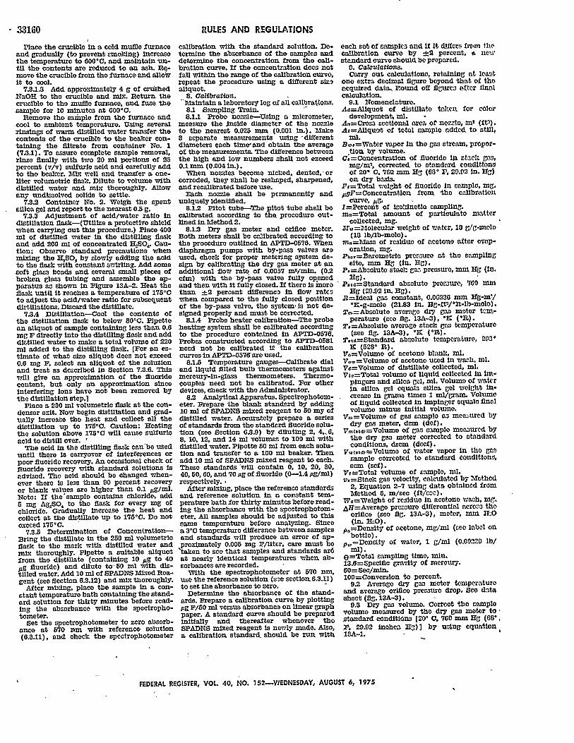
3 23160Place the crucible in a cold muffle furnace
and gradually (to prevent smoking) increasethe temperature to 600"C, and maintain un-til the contents are reduced to an ash. Re-move the crucible from the furnace and allowit to cool.
7.3.1.3 Add approximately 4 g of crushedNaOH to the crucible and mix. Return thecrucible to the muffle furnace, and_ fuse thesample for 10 minutes at 600°C.
Remove the sample from the furnace andcool to ambient temperature. Using severalrinsings of warm distilled water transfer thecontents of the crucible to the beaker con-taining the filtrate from container No. 1(7,3.1). To assure complete sample removal,rinse finally with two 20 ml portions of 25percent (v/v) sulfuric acid and carefully addto the beaker. Mix well and transfer a one-liter volumetric flask. Dilute to volume withdistilled water and mix thoroughly. Allowany undissolved solids to settle.
7.3.2 Container No. 2. Weigh the spentsilica gel and report to the nearest 0.5 g.
7.3.3 Adjustment of acid/water ratio indistillation flask-(Utllze a protective shieldwhen carrying out this procedure.) Place 400ml of distilled water In the distilling flaskand add 200 ml of concentrated HtSOS. Cau-tion: Observe standard precautions whenmixing the HSO, by slowly adding the acidto the flask with constant swirling. Add somesoft glass beads and several small pieces ofbroken glass tubing and assemble the ap-paratus as shown in Figure 13A-2. Heat theflask until it reaches a temperature of 175°Cto adjust the acid/water ratio for subsequentdistillations. Discard the distillate.
7.3.4 Distillation-Cool the contents ofthe distillation flask to below 801C. Pipettean aliquot of sample containing less than 0.6mEg F directly into the distilling flask and adddistilled water to make a total volume of 220ml added to the distilling flask. [For an es-timate of what size aliquot does not exceed0.6 mg F, select an aliquot of the solutionand treat as described in Section 7.3.6. Thiswill give an approximation of the fluoridecontent, but only an approximation sinceinterfering ions have not been removed bythe distillation step,]
Place a 250 ml volumetric flask at the con-denser exit. Now begin distillation and grad-ually increase the heat and collect all thedistillation up to 175"C. Caution: Heatingthe solution above 175°0 will cause sulfuricacid to distill over. I
The acid in the distilling flask cantb uSeduntil there is carryover of interferences orpoor fluoride recovery. An occasional check offluoride recovery with standard solutions Isadvised. The acid should be changed when-ever there is less than 90 percent recoveryor blank values are higher than 0.1 /g/ml.Note: If the'sample contains chloride, add5 mg AgSO64 to the flask for every mg ofchloride. Gradually increase the heat andcollect at the distillate up to 175*C. Do notexceed 175C.
7.3.5 Determination of Concentration-Bring the distillate in the 250 ml volumetricflask to the mark with distilled water andmix thoroughly. Pipette a suitable aliquotfrom the distillate (containing 10 pg to 40pug fluoride) and dilute to, 50 ml with dis-tilled water. Add 10 ml of SPADNS Mixed Rea-gent (see Section 6.3.12) and mix thoroughly.
After mixing, place the sample in a con-stant temperature bath containing the stand-ard solution for thirty minutes before read-ing the absorbanco with the spectropho-tometer.
Set the spectrophotometer to zero absorb-ance at 570 nm with reference solution(0.3.11), and check the spectrophotometer
RULES AND REGULATIONS
calibration with the standard solution. De-termine the absorbance of the samples anddetermine the concentration from the call-bration curve. If the concentration does notfall within the range of the calibration curve,repeat the procedure using a different slznaliquot.
8. Calibration.Maintain a laboratory log of all calibrations.8.1 Sampling Train.8.1.1 Probe nozzle-Using a micrometer.
measure the inside diameter of the nozzleto the nearest 0.025 mm (0.001 In.). Make3 separate measurements using *differentdiameters qach time, and obtain the averageof the measurements. The difference betweenthe high and low numbers shall not exceed0.1 mm (0.004 in.).
When nozzles become nicked, dented, 'orcorroded, they shall be reshaped, sharpened,and recalibrated before use.
Each nozzle shall be permanently anduniquely Identified.
8.1.2 Pitot tube-The piot tube shall becalibrated according to the procedure out-lined in Method 2.
8.13 Dry gas meter and orifice meter.Both meters shall be calibrated according tothe procedure outlined in APTD-0576. Whendiaphragm pumps with by-pass valves areused, check for proper metering system de-sign by calibrating the dry gas meter at anadditional flow rate of 0.0057 m/min. (0.2cfm) with the by-pass valve fully openedand then with it fully closed. If there Is morethan ±2 percent difference In flow rateswhen. compared to the fully closed positionof the by-pass valve, the system, is not de-signed properly and must be corrected.
8.1.4 Probe heater calibration-The probeheating system shall be calibrated accordingto the procedure contained in APTD-0576.Probes constructed according to APTD-058lneed not be calibrated If the calibrationcurves in APTD-0576 are used.
8.1.5 Temperature gauges--Calibrate dialand liquid filled bulb thermometers againstmercury-in-glass thermometers. Thermo-couples need not be calibrated. For otherdevices, check with the Administrator.
8.2 AnalyticalApparatus. Spectrophotom-eter. Prepare the blank standard by adding10 ml of SPADNS mixed reagent to 50 my ofdistilled water. Accurately prepare a seriesof standards from the standard fluoride solu-tion (see Section 6.3.9) by diluting 2, 4,6,8, 10, 12, and 14 ml volumes to 100 ml withdistilled water. Pipette 50 ml from each solu-tion and transfer to a 100 ml beaker. Thenadd 10 ml of SPADNS mixed reagent to each.These standards 'will contain 0, 10. 20, 30,40, 50. 60, and 70.pg of fluoride (0-1.4 Ag/ml)respectively.I
After mixing, place the reference standardsand reference solution in a constant tem-perature bath-for thirty minutes before read-ing the absorbance with the spectrophotom-eter. All samples should be adjusted to thissame temperature before analyzing. Sincea 3°G temperature difference between samplesand standards will produce an error of ap-proximately 0.005 mg F/liter, care must betaken to see that samples and standards ar6at nearly identical temperatures when ab-sorbances are recorded.
With the spectrophotometer at 570 nm,use the reference solution (see section 6.3.m)to set the absorbance to zero.
Determine the absorbance of the stand-ards. Prepare a calibration curve by plottingpg F/50 ml versus absorbance on linear graphpaper. A standard curve should be preparedinitially and thereafter whenever theSPADNS mixed reagent Is newly made. Also,a calibration standard. should be run with
each set of samples and If It differs fro-m thocalibration curve by -J2 percent, i newstondard curve should be prepared.
9. CalcuZations.Carry out calculatons, retaining at leart
one extra decimal figuro beyond that of theacquired data, Round off flgures aftor finalcalculation.
9.1 Nomenclature.As=Aliquot of distillate taken. for color
development, ml.A.=Cross sectional area of nozzle, ma (ft).At=Allquot of total sample added to otill,
ml.B,=Water vapor In the gas stream, proper-
tion by volume.C;=Concentratlon of fluoride in atack gas,
mg/m', corrected to standard conditionsof 200 C, 760 mm Hg (60, 11, 29.92 In. Hg)on dry basis.
F#=Total weight of fluoride In spample, Mg,AgF= Concentration from, the calibration
curve, /Ag.I=Percent of Isokinetic sampling.mn=Total amount of particulato matter
collected, mg.M.f,=2olecular weight of water, 10 g/g-molo
(18 lb/lb-molo).m 0 =Mass of residue of acetone aftor evap-
oration, mg.Prb,=Barometrlo pressure at the sampling
site, mm Hg (in. Hg).P, =Abzolute stack gas pressuro, min Hg (In.
Hg).P.td=Standard absolute pressure, 700 mm
Hg (29.92 in. Hg).B=Ideal gas constant, 0.00230 min Hg-m5/
*z-g-molo (21.83 in. Hg-fit/1t-lb-molo).T0 =Abzolute average dry gas motor tcn-
peraturo (see fig. 13A-3), "r, (').T*=Abseluto average stack gas temperature
(see fig. 13A-3), *X (*R).T.ad=Standard absolute temperature, 2130
K (528° nl).
VO=Volumo of acetone blank, ml,Vo=Volumo of acetone used in watlh, ml.Vd=Volumo of distillate collected, ml.Va,=Total volume of liquid collected in It -
pingers and silica gel, ml. Volume of waterin silica gel equals silica gel weight In-crease in grams times 1 ml/gram Volumeof liquid collected in Impinger equals finalvolume minus initial volume.
V,=Volume of gag sample a3 men ured bydry gas meter, dem (def).
Vm.ta)=Volume of ga sample meoaured bythe dry gas meter corrected to standardconditions, dscm (decf).
Vw(9td)=Volumo of water vapor In the gssample corrected to standard conditions,scm (scf).
V,=Total volume of sample, ml,v,=Stack gas velocity, calculated by Method
2, Equation 2-7 using data obtained fromMethod 5, m/sec (ft/see).
W.=Weight of residue In acetone wash, M.IAH=Averago pressure differential aero.s the
orifice (see fig. 13A-3), meter, mm X-0(in. ItO).
p,=Density of acetone, rag/ml (see label onbottle).
p,='Denslty of water, 1 g/ml (0.00220 lb/
mli).(=Total sampling time, min.13.6=Specific gravity of mercury.60=Sec/min.100=Conversion to percent.
9.2 Average dry gas motor temperatureand average orifice prezsuro drop. See datosheet (fig. 13A-3).
9.3 Dry gas volume. Coritot the samplevolume measured by the dry gas moor to,standard conditions [20' 0, 760 mn Hg (00",
. 20.92 nhca Hg)] by uslng equation13A-1.
FEDERAL REGISTER, VOL. 40, NO. 152-VIEDNESDAY, AUGUST 6, 1975

RULES AND REGULATIONS 3
r AHT ( V= Tl r r i rj . Pha,+AH13.6
equation 13A-1where:
K=0.3855 K/mm HZg for metric units.=17.65 °R/Ln. Hg for English units.
9.4 Volume of water vapor.
p" =Ky,.
where:E=0.00134 m3/ml for metric units.
=0.0472 ft/rnl for English units.9.5 Moisture content.
"[r.(tt
equation 13A-3
If the liquid droplets are prezent In thegas stream assume the stream to be saturatedand use a psychrometrio chart to obtain anapproximation of the moisture percentage.
9.6 Concentration.9.6.1 Calculate the amount of fluoride In
the sample according to Equation 13A-4.
= , (u F)
equation 13A-4where:
K= 10-3 mg/pg.9.6.2 Concentration of fluoride In stack
gas. Determine the concentration of fluorideIn the stack gas according to Equation 13A-5.
F,
equation 13A-5where:
IC=35.31 ft 3/m.
9.7 Isokinetlc variation.9.7.1 Calculations from raw data.
100 T. [KVe+ (VIT.,) (P6.,+ IH113.6)160 vo P,.
where:K=0.00346 mm Hg-ms/ml-OK for metric
units.=0.00267 In. Hg-ft3/ml-R for English
units.9.7.2 Calculations from Intermediate val-
ues.
= T.Vr,.d)P., d 100TtdvOA.P, 60 (1-B.,)
=K ---T. IP,v, A.O
where:IC=4.323 for metric units.
=0.0944 for English units.9.8 Acceptable results. The following
range sets the limit on acceptable isoknetlcsampling results:
If 90"percent <I< 110 percent. the re-sults are acceptable. If the results are low Incomparison to the standards and I is beyondthe acceptable range, the Administrator mayoption to accept the results: Use reference7.4 to make judgments. Otherwise, reject theresults and repeat the test.
10. References. 'Bellack, Ervin, "Simplified Fluoride Dis-
tillation Method," Journal of the AmericanWater Works Association #50: 530-6 (1958).
MacLeod, Kathryn E., and Howard L. Crist,"Comparison of the SPADNS-ZirconiumLake and Specific Ion Electrode Methods of
equation 13A-2
equation 13A-6
(I-B,) equation 13A-7
Fluoride Determination in Stack EnmlronSamples." Analytical Chemistry 45: 1272-1273 (1973).
Martin, Robert M, "Construction Detailsof 1rokdnetlc Source Sampling Equipment."Environmental Protection Agency, Air Pollu-tlon Control Office Publication Xo. APTD-0581.
1973 Annual BRo: of ASTM Standarda,Part 23, Designation: D 1179-72.
Rim. Jerome J., ,1aintenance, Calibra-tion, and Operation of Irokinetec SourceSampling Equipment." Environmental Pro-tection Agency, Air Pollution Control OfficePublication No. APTP-0576.
Standard Methods for the Examination ofWater and Waste Wdtcro publlsed jointlyby American Public Health A.zocistion.American Water Workas As:zclation andWater Pollution Control Federation, 13thEdition (1971).
FEDERAL REGISTER, VOL 40, NO. 152-WEDNESDAY, AUGUST 6, 1975
3.31[61
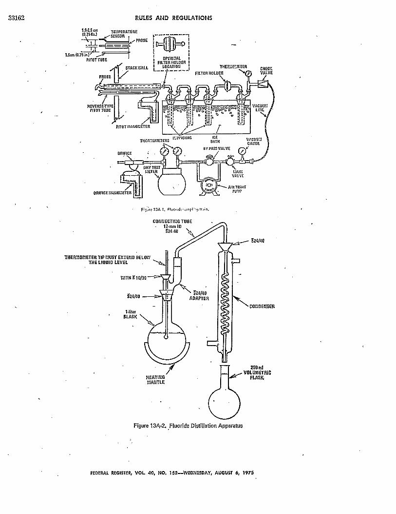
RULES AND REGULATIONS
1.9-2.S cm
Figure1 13A I. Fiulorid triin.
THERMOMETER TIP MUST EXTEND BELOWTHE LIQUID LEVEL
WITH 1O3O -
124/40 -
1-literSLASK \.
Figure 13A-2. Fluoride Distillation Apparatus
FEDERAL REGISTER, VOL 40, NO. 152-EDNESDAY, AUGUST 6, 1975
- 24/40
COOEMER
33162
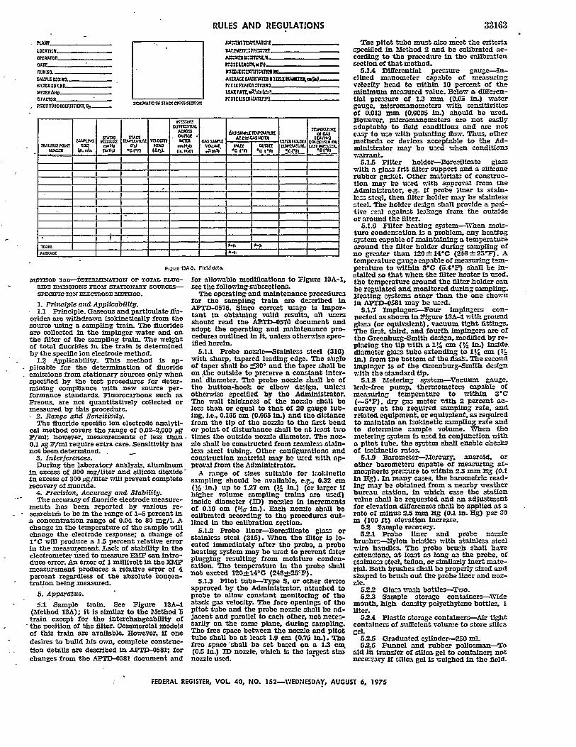
LOCATIONCEATO __R____ATEA
CFACT _R-----------PCDTT0BEco 'anrr. SoeiATnSAC[oe==ETIS
RULES AND REGULATIONS
UAXPAtTlr.Alrrft
tP01USEmlmATnuI1
Avazc u=:HtaXhm!W ~ W.......
?s3zrrA aa ll I
IA, - OLT 1i. r. H.A *Co5 n CAes ;HO AnISE 1tU [InII l'W Un..li
TOTAL.AVTMGE A_____ ________
METHOD SB--DETERMINATION OF TOTAL FLUO- for allowable modifications to Figure I3A-1,RIDE EMISSIONS FROM STATIONARY SOURCES- see the followingsubsections.SPECIFIC ION ELECTRODE METHOD. The operating and maintenance procedures
1. Principle and Applicability, for the sampling train are descrlbed In1.1 Principle. Gaseousand particlate fu- APTD-0576. Since correct usage Is Impor-
1.1~ ~ ~ ~ ~ ~ ~i ricpeGaeuanpaiclte u tant In obtaining valid results. all usersorldes are withdrawn isokinetically from the shul nread the ATD-0570 document andsource using a sampling train. The fluoridesare collected in the impinger water and on adopt the operating and maintenance pro-
the filter of the sampling train. The weight cedures outlined In It, unless otherwise spec-
of total fluorides in the train is determined ified herein.
by the specific ion electrode method. 5.1.1 Probe nozzle-Stainless steel (310)1.2 Applicability. This method is ap- with sharp, tapered leading edge. The abglo
plicable for the determination of fluoride of taper shall be f300 and the taper shall beemissions from stationary sources only when on ,the outside to preserve a constant Inter-specified by the test procedures for deter- nal diameter. The probe nozzle chall be ofmining compliance with new source per- the button-hook or elbow design. unle.sformance standards. Fluorocarbons such as otherwise specified by the Administrator.Freons, are not quantitatively collected or The wall thickness of the nozzle shall bemeasured by this procedure. less than or equal to that of 20 gauge tub-
2. Range and Sensitivity. Ing. I.e. 0.165 cm (0.065 In.) and the distanceThe fluoride specific ion electrode analyti- from the tip of the nozzle to the first bend
cal method covers the range of 0.02-2,000 pg or point of disturbance shall be at least twoF/mi; however, measurements of less than - times the outside nozzle diameter. The noz-0.1 jg F/mi require extra care. Sensitivity has zle shall be constructed from seamless stain-not been determined. - less steel tubing. Other conilguratlons and
3. Interferences. construction material may be uted with ap-During the laboratory analysis, aluminum proval from the Administrator.
in excess of 300 mg/liter and silicon dioxide' A range of sizes suitable for IsokineticIn excess of 300 jg/liter will prevent complete sampling should be available, e.g.. 0.32 cmrecovery of fluoride. (% In.) up to 1.27 cm (! In.) (or larger If
4. Precision, Accuracy and Stability. higher volume sampling trains are used)The accuracy of fluoride electrode measure- inside diameter (ID) nozzles In increments
ments has been reported by various re- of 0.16 cm (VIW in.). Each nozzle shall be- searcher to be in the range of 1-5 percent in calibrated according to the procedures out-
a concentration range of 0.04 to 80 mg/l. A lined in the calibration section.change in the temperature of the sample will 5.1. Probe liner-BoroslIcato glas orchange the electrode response; a change of stainless steel (316). When the filter Is lo-1°C will produce a 1.5 percent relative error cted immediately after the probe. a probein the measurement. Lack of stability in the hatd imdte y aer t prbe aiprelectrometer +dsed to measure EInF can Intro- heating system may be used to prevent -llerduce error. An error of 1 millivolt in the EM plugging reslting from moiture cobden-measurement produces a relative error of 4 atlon. The temperature in the probe shallpercent regardless of the absolute concen- not exceed 120_.141C (248:-b±S2 ).tration being measured. 5.1.3 Pitot tube-Type S, or other device
approved by the Administrator, attached to5. Apparatus. probe to allow constant monitoring of the
5.1 Sample train. See Figure 13A-1 stack gas velocity. The face openings of the
(Method 13A); it Is similar to the method 5 pitot tube and the probe nozzle shall be ad-train except for the interchangeability of Jacent and parallel to each other, not neces-the position of the filter. Commercial models sarnly on the same plane, during sampling.of this train are available. However. if one The free space between the nozzle and pltot
tube shall be at least b.0 cm (0.75 In.). Thedesires to build his own, complete construc- free sh shal l be set b d on a .3 Thetion details are described In APTD-0581; for (0.5 in.) ID nozzle, wlhich is the largest sizchanges from the APTD-0581 document and nozzle used.
33163
The pitot tube must also meet the criteriaspecifled In Method 2 and be calibrated ac-cording to the procedure in the calibrationsection of that method.
51A DIfferentia pressure gauge-In-clined manometer capable of measuringvelocity head to within 10 percent of theminimum measured value. Below a differen-tial pressure of 1.3 mm (0.05 in.) watergauge. micromanometera with sensitivitiesof 0.013 mnm (0.0005 in.) should be used.However, m1cromanometers we not easilyadaptable to field conditions and are noteasy to us with pulsating flow. Thus, othermethods or devices acceptable to the Ad-minIstrator may be used when conditionswarrant,
5.1.5 n~lter holder-Borosillcate glass'with a gla frit filter support and a siliconerubber gas!:et. Other materials of construc-tion may be used with approval from theAdministrator, e. . if probe liner is stain-le- stepl. then filter holder may be stainlesssteel. The holder design shall provide a pos-tive ceal against leakage from the outsideor around the filter.
5.1.6 Filter heating system-When mois-ture condensation Is a problem, any heatingsystem capable of maintaining a temperaturearound the filter holder during sampling ofno greater than l20"-14*C (248---25*F). Atemperature gauge capable of measuring tem-perature to within 3C (5.4F) shall be In-stalled so that when the filter heater Is used.the temperature around the filter holder canbe regulated and monitored during sampling.Heating systems other than the one shownin APTD-0581 may be used.
5.1.7 Impingers-Four impingers con-nected as shown in Figure 13A-i with groundglas (or equivalent), vacuum tight fittings.The first, third, and fourth impingers are ofthe Greenburg-Smlth design, modified by re-placing the tip with a 11/4 cm (% In.) insldediameter glas. tube extending to 1 cm (%in.) from the bottom of the flasl.. The secondimpinger is of the Greenburg-Smith designwith the standard tip.
5.1.8 Metering system-Vacuum -gauge.leak:-free pump. thermometers capable ofmeasuring temperature to within 3*C(5P). dry gas meter with 2 percent ac-curacy at the required sampling rate, andrelated equipment or equivalent, as requiredto maintain an hokinetic sampling rate andto determine cample volume. When themetering system Is uzed In conjunction witha pitot tube. the system shall enable checksof Isoldnetlc rates.
5.1.9 Barometer-Mercury, aneroid, orother barometers capable of measuring at-mospherlc precure to within 2.5mm Hg (0.1in Hg). In many cases. the barometric read-Ing may be obtained from a nearby weatherbureau station. In which case the stationvalue shall be requested and an adjustmentfor elevation differences shall be applied at arate of minus 2.5 mm Hg (0.1 in. Hg) per 30m (100 fIt) elevation Increase.
5.2 Sample recovery.5.2.1 Probe liner and probe nozzle
brushes-Nylon brlstle with stainless steelwire handles. The probe brush shall haveextensions., at least as long as the probe, ofstainless steel, teflon, or similarly inert mate-ril. Both brushes shall be properly sized andshaped to brush out the probe liner and noz-zle.
5.2.2 Glass wash bottIes-Two.5.2.3 Sample storage containers-Wide
mouth, high density polyethylene bottles, Iliter.
5.2.4 Plastic storage containers-Air tightcontainers of suinclent volume to store silicagel
5.2.5 Graduated cylinder-250 ml.5.2.6 Funnel and rubber pollceman-To
aid In transfer of silica gel to container; notnecessary f silica gel is weighed In the field.
FEDERAL REGISTER, VOL 40, NO. 152-WEDNESDAY, AUGUST 6, 1975

33164
5.3 Analysis.5.3.1 Distillation apparatus--Glass distil-
lation apparatus assembled as shown In Fig-ure 13A-2 (Method 13A).
5.3.2 Hot plate-Capable of heating to500oc.
5.3.3 Electric muffle furnace-Capable ofheating to 600"C.
5.3.4 Crucibles--Nickel, 75 to 100 nlcapacity.
5.3.5 Beaker-1500 ml.5.3.6 Volumetric flask-50 ml.5.3.7 Erlenmeyer flask or plastic bottle-
500 mi.5.3.8 Constant temperature bath-Cap-
able of maintaining a constant temperatureof --1.0°C in the range of room temperature.
5.3.9 Trip balance-300 g capacity tomeasure to ±0.5 g.
5.3.10 Fluoride ion activity sensing elec-trode.
5.3.11 Reference electrode--Single Junc-tion; sleeve type. (A combination-type elec-trode having the references electrode andthe fluoride-ion sensing electrode built Intoone unit may also be used).
5.3.12 Electrometer-A pH meter withmillivolt scale capable of -0.1 my resolu-tion, or a specific ion meter made specificallyfor specific ion use.
5.3.13 Magnetic stirrer and TFE fluoro-darbon coated stripping bars.
6. Reagents.6.1 Sampling.6.1.1 Fllters-Whatman No. 1 filters, or
equivalent, sized to fit filter holder.6.1.2 Silica get-Indicating type, 6-16
mesh. If previously used, dry at 175°C(350-F) for 2 hours. New silica gel may beused as received.
6.1.3 Water-Distilled.0.1.1 Crushed ice.6.1.6 Stopcock grease-Acetone insoluble,
heat stable silicone grease. This is not neces-sary if screw-on connectors with teflonsleeves, or similar, are used.
0.2 Sample recovery.6.2.1 Water-Distilled from same con-
taier as 6.1.3.0.3 Analysis.6.3.1 Calcium oxide (CaO)-Certified
grade containing 0.005 percent fluoride orless.
6.3.2 Phenolphthalein Indicator--0.1 per-cent in 1: 1 ethanol water mixture.
6.3.3 Sodium hydroxide (NaOH)-Pel-lets, ACS reagent grade or equivalent.
03.4 Sulfuric* acid (HSO)--CGoncen-trated, ACS reagent grade or equivalent.
6.3.' Flltersr-Whatman No. 541, orequivalent.
0.3.6 Water-Distilled, from same con-tainer as 6.1.3.
6.3.7 Total Ionic Strength AdjustmentBuffer (TISAB)-Place approximately 600ml of distilled water in a 1-liter beaker. Add57 ml glacial acetic acid, 58 g sodium chlo-ride, and 4 g CDTA (Cyclohexylene dinitrllotetraacetic acid). Stir to dissolve. Place thebeaker in a water bath to cool it. Slowlyadd 5 M NaOH to the solution, measuringthe pH continuously with a calibrated pH/reference electrode pair, until the pH is 5.3.Cool to room temperature. Pour into a I-literflask and dilute to volume with distilledwater. Commercially prepared TISAB-buffermay be substituted for the above.
6.3.8 Fluoride Standard Solution-0.1 Mfluoride reference solution. Add 4.20 grams ofreagent grade sodium fluoride (Na?) to a 1-liter volumetric flask and add enough dis-tilled water to dissolve. Dilute to volumewith distilled water.
7. Procedure.NOTE: The fusion and distillation steps of
this procedure will not be required, if It canbe shown to the satisfaction of the Admin-Istrator that the samples contain only water-soluble fluorides.
RULES AND REGULATIONS
7.1 Sampling. The sampling shall be con-ducted by competent personnel experiencedwith this test procedure.
7.1.1 Pretest preparation. All train com-ponents shall be maintained and calibratedaccording to the procedure described InAPTD-0576, unless otherwise specifiedherein.
Weigh approximately 200-300 g of silica geln air tight containers to the nearest 0.5 g.
Record the total weight, both silica gel andcontainer, on the container. More silica gelmay be used but care should be taken duringsampling that it is not entrained and carriedout from the impinger. As an alternative, thesilica gel may be weighed directly in the im-pinger or its sampling holder just prior tothe train assembly.
7.1.2 Preliminary determinations. Selectthe sampling site and the minimum numberof sampling points according to Method 1 oras specified by the Administrator. Determinethe stack pressure, temperature, and therange of velocity heads using Method 2 andmoisture content using ApproximationMethod 4 or its alternatives for the purposeof making isokinetic sampling rate calcula-tions. Estimates may be used. However, finalresults will be based on actual measure-ments made during the test.
Select a nozzle size based on the range of'velocity heads such that it is not necessaryto change the nozzle size in order to maintainsokinetic sampling rates. During the run, donot change the nozzle size. Ensure that thedifferential pressure gauge is capable ofmeasuring the ninimum velocity head valueto within 10 percent, or as specified by theAdministrator.
Select a suitable probe liner and probelength such that all traverse points cab besampled. Consider sampling from oppositesides for large stacks to reduce the length ofprobes.
Select a total sampling time greater thanor equal to the minimum total samplingtime specified in the test procedures for thespecific industry such that the sampling timeper point is not less than, 2 min. or selectsome greater time interval as specified bythe Administrator, and such that the samplevolume that will be taken will exceed the re-quired minimum total gas sample volumespecified in the test procedures for the spe-cific industry. The latter is based on an ap-proximate average sampling rate. Note alsothat the minimum total sample volume Iscorrected to standard conditions.
It is recommended that a half-integral orintegral number of minutes be sampled ateach point in order to avoid timekeepingerrors.
In some circumstances, e.g. batch cycles, Itmay be necessary to sample for shorter timesat the traverse points and to obtain smallergas sample volumes. In these cases, the Ad-ministrator's approval must first be obtained.
7.13 Preparation of collection train. Dur-ing preparation and assembly of the samplingtrain, keep all openings where contaminationcan occur covered until just prior to assemblyor until sampling is about to begin.
Place 100 ml of water in each of the flrsttwo impingers, leave the third Impingerempty, and place approximately 200-300 g ormore, if necessary, of prewelghed silica gel inthe fourth impinger. Record the weight ofthe silica gel and container on the data sheet.Place the empty container in a clean placefor later use in the sample recovery.
Place a filter in the filter holder. Be surethat the filter is properly centered and thegasket properly placed so as to not allow thesample gas stream to circumvent the filter.Check filter for tears after assembly Is com-pleted.
'When glass liners are used, install selectednozzle using a Vlton A 0-ring; the Viton AO-ring is installed as a seal where the nozzle
is connected to a glass liner, See APTD-057for details. When metal liners are used, In-stall the nozzle ag above or by a lealk freodirect mechanical connection. Mark the probewith heat resistant tape or by come othermethod to denote the proper distance initothe stack or duct for each sampling point,
Unless otherwise specified by the Admin-strator, attach a temperature probe to themetal sheath of the sampling probe so thatthe sensor extends beyond the probe tip anddoes not touch any metal. Its position shouldbe about 1.0 to 2.54 cm (0.75 to 1 in.) fromthe pito tube and probe nozzle to avoid In-terference with the gas flow.
Assemble the train as shown In Figure13A-1 (Method 13A) with the filter betweenthe third and fourth impingers. Alterna-tively, the filter may be placed between theprobe and first impInger. A filter heating sys-tem may be used to prevent moisture con-densation, but the temperature around thefilter holder shall not exceed 120041410(248±250F). [(Note: Whatman No. 1 filterdecomposes at 1501C (3001?)).] Recordfilter location on the data sheet.
Place crushed ice around the impingera,7.1.4 Leak check procedure--After the
sampling train has been assembled, turn onand set (If applicable) the probe and filterheating system(s) to reach a tomporaturosufficient to avoid condensation in the probe,Allow time for the temperature to stabilize.Leak check the train at the sampling site byplugging the nozzle and pulling a 380 mmHg (15 in. Hg) vacuum. A leakage rate In ex-cess of 4% of the average sampling rate of0.0057 m3/min. (0.02 cfm), whichever is less,Is unacceptable.
The following leak chock instruction forthe sampling train described In APTD-0570and APTD-0581 may be helpful. Start thepump with by-pass valve fully open andcoarse adjust valve completely closed. Par-tially open the coarse adjust valve and slow-ly close the by-pass valve until 380 mm Hg(15 in. Hg) vacuum is reached. Do Not re-verse direction of by-pass valve. This willcause water to back up into the filter holder.If 380 mm Hg (15 in. Hg) Is exceeded, eitherleak check at this higher vacuum or end theleak check as described bolow and start over,
When the leak check is completed, firstslowly remove the plug from the inlet to theprobe or filter holder and immediately turnoff the vacuum pump. This prevents thewater in the impingers from being forcedbackward into the filter holdef' (if placedbefore the tmpingers) arid silica gel fromUbeing entrained backward into the thirdimpinger.
Leak checks shall be conducted as de-scribed whenever the train Is disengaged, e.g.for silica gel or filter changes during the test,prior to each test run, and at the completionof each test run. If leaks are found to be Intexcess of the acceptable rate, the test vill beconsidered Invalid. To roduce lest time due toleakage occurrences, it Is recommended thatleak checks be conducted between portchanges.
7.1.5 Particulate train operation-Duringthe sampling run, an lsokinetie samplingrate within 10%, or as specified by the Ad-ministrator, of true isokinotic shall be main-tained.
For each run, record the data required o11the example data sheet shown In Figure13A-3 (Method 13A). Be sur6 to record theinitial dry gas meter reading. Record thedry gas meter readings at the beginning andend of each sampling time increment, whenchanges in flow rates are made, and whensampling is halted. Take other data pointreadings at least once at each sample pointduring each time increment and additionalreadings when significant changes (20%variation in velocity head readings) neces-
FEDERAL REGISTER, VOL. 40, NO. 152-WEDNESDAY, AUGUST 6, 1975

RULES AND REGULATIONS
sitate additional adjustments in flow rate. Besure to level and zero the manometer.
Clean the portholes prior to the test runto minlmize chance of sampling depositedmaterial. To begin sampling, remove theiozzle cap, verify (if applicable) that theprobe heater Is working and filter heater is
- up to temperature, and that the pitot tubeand probe are properly positioned. Positionthe nozzle at the Arst traverse point withthe tip pointing directly into the gas stream.Immediately start the pump and adjust theflow to isokinetic conditions. Nomographwareavailable for sampling trains using type Spitot tubes with 0.85± 0.02 (coefficients (CP),and when sampling in air or a stack gas withequivalent density (molecular weight, M.equal to 29=41), which aid in the rapid ad-justment of the isokinetic sampling ratewithout excessive computations. APTID-0576details the procedure for using these nomo-graphs. If C6 and Md are outside the abovestated ranges, do not use the nomograph un-less appropriate steps are taken to compen-sate for the deviations.
Whell the stack is under significant neg-ative pressure (height of Impinger stem).take cae to close the coarse adjust valvebefore Inserting the probe into the stack toavoid water backing into the filter holder. Ifnecessary, the pump may be turned on withthe coarse adjust valve closed.
When the probe Is in position, block offthe openfngs around the probe and portholeto prevent unrepresentative dilution of thegas stream.
Traverse the stack cross section, as re-* quired by Method 1 or as specified by the Ad-
ministrator, being careful not to bump theprobe nozzle into the stack walls whensampling near the walls or when removingor inserting the probe through the port-holes to minimize chance of extracting de-posited material.
During the test run, make periodic adjust-ments to keep the probe and (if applicable)filter temperatures at their proper values.Add more ice and, if necessary, salt to theice bath, to maintain a temperature of lessthan 20-C (68'P) at the Impinger/slica geloutlet, to avoid excessive moisture losses.Also, periodically check the level and zeroof the manometer.
If the pressure drop across the filter be-comes high enough to make isokinetic sam-pling difficult to maintain, the filter may bereplaced In the midst of a sample run. It isrecommended that another complete filter as-sembly be used rather than attempting tochange the filter Itself. After the new filteror filter assembly is Installed, conduct aleak check. The final emission results shallbe based on the summation of all filtercatches.
A single train shall be used for the entiresample run, except for filter and silica gelchanges. However, if approved by the Admin-istrator, two or more trains may be used fora single test run when there are two or moreducts or sampling ports. The final ezhission
-results shall be based on the total of allsampling train catches.
At the end of the sample run, turn off thepump, remove the probe and nozzle fromthe stack, and record the final dry gas meterreading. Perform a; leak check.' Calculatepercent Isokinetic (see calculation section) todetermine whether another test run sholdbe made. If there is difficulty in mintainingisokinetic rates due to source conditions, con-sult with the Administrator for possiblevariance on the isokinetic rates.
'With acceptability of the test run to bebased on the same criterion as in 7.1.4.
7.2 Sample recovery. Proper cleanup pro-cedure begins as on as the probo is re-moved from the stack at the end of thesampling period.
When the probe can be safely handled,wipe off all external particulate matter nearthe tip of tho probe nozzlo and place a capover It to keep from losing part of the sam-ple. Do not cap ol the probe tip tightlywhile the sampling train is cooling down.as this would create a vacuum In the filterholder, thus drawing water from the Im-pingers into the filter.
Before moving the sample train to thecleanup site, remove the probe from thesample train, ivpe off the silicone grease,and cap the open outlet of the probe. Becareful not to loze any condensate, if pre-ent. Wipe off the silicone grease from thefilter Inlet where the probe was fastenedand cap It. Remove the umbilical cord fromthe last Impinger and cap the impinger. Afterwiping off the silicone grease, cap off thefilter holder outlet and impinger inlet.Ground glass stoppers, plastic caps, or serumcaps may be used to close theze openings.
Transfer the probe and ilter-ImpInger as-sembly to the cleanup arma. This area shouldbe clean and protected from the wind ro thatthe chances of contaminating or losing thesample will be minimized.
Inspect the train prior to and during dis-assembly and note any abnormal condition3.Using a graduated cylinder, measure and re-cord the volume of the water in the firstthree impingers, to the nearest ml; any con-densate in the probe should be included inthis determination. Treat the samples asfollows:
No. 71778, Pauley, J. E., 8-5-75
7.2.1 Container No. 1. Transfer the im-pinger water from the graduated cylinderto this container. Add the .flter to thiscontainer. Wash all sample expo:Ld sur-faces, Including the probe tip, probe, firstthree Impinger, impinger connectors, filterholder, and graduated cylinder thoroughlywith distilled water. Wash each componentthree separate times with water and cleanthe probe and nozzle with brushe3. A imx-imum wash of 500 ml is used, and the wah-ings are added to the sample containerwhich must be made of polyethylene.
7.2.2 Container No. 2. Transfer the silicagel from the fourth Impinger to this con-tainer and seal.
7.3 Analysis. Treat the contents of eachsample container as described below.
7.3.1 Container No. 1.7.3.1.1 Filter this container's contents, In-
cluding the Whatmia No I filter, throughWhatman No. 541 filter paper, or equivalentInto a 1500 ml beaker. Nozz: If filtrate vol-ume exceeds 000 ml mako filtrate basic withNaOH to phenolphthalein and evaporate toless than 900 ml.
7.3.1.2 Place the Vhatman No. 541 filtercontaining t~e Insoluble matter (includingthe Whatman No. 1 filter) in a nickel cru-cible, add a few ml of water and maceratothe filter with a glam rod.
Add 100 mg CaO to the crucible and mlxthe contents thoroughly to form a slurry. Adda couple of drops of phenolphthalein indi-cater. The indicator will turn red In a basicmedium. The _slurry .cshould remain basicduring the evaporation of the water orfluoride ion will be lot. If the indicatorturns colorless during the evaporation, anacidic condition is indicated. If this happensadd CaO until the color turns red again.
Place the crucible In a hood under in-frared lamps or on a hot plate at low heat.Evaporate the water completely.
After evaporation of the water, place thecrucible on a hot plate under a hood and,lowly increas the temperature until thepapar chars. It may take mveral hours forcomplete charring of the filter to occur.
Place the crucible in a cold muffle furnaceand gradually (to prevent smoking) increasethe temperaturo to 600OC. and maintain untilthe contenta are reduced to an ash. Removethe crucible from the furnace and allow It tocooL
7.3.1.3 Add approximately 4 g of crushedNraOH to the crucible and rix. Return thecruciblo to the muffle furnace, and fuse thesample for 10 minutes at 600"C.
Remove the sample from the furnace andcool to ambient temperature. Using severalrinsinga of warm distilled water transferthe contents of the crucible to the beakercontaining the filtrate from container No.1 (7.3.1). To assure complete sample re-moval, rinse finally with two 20 ml portionsof 25 percent (v/v) sulfuric acid and care-fully add to the beaker. Lix well and trans-fer to a one-liter volumetric flask. Diluteto volume with distilled water and mixthoroughly. Allow any undissolved solids tocattle.
7.3.2 Containez No. 2. Welgh the. spentsilica gel and report to the nearest 0.5 g.
7.3.3 Adjustment of acd/water ratio indLstilatlon r -is-(-Uilze a protective shidwhen carrying out this procedure). Place 400ml of distilled vater in the distilling flaskand add 200 ml of concentrated HeSO,. Cau-tion: Obcerve standard precautions whenm ing the H150 , by slowly adding the acidto the fl1 with constant swirling . Add somesoft glam beads and several small pieces ofbrolmn glam tubing and aaremble the -ap-paratus as shown In Figure 13A-2. Heat thefl until it reache3 a temperature of 175"Cto adjust the acid/water ratio for subsequentdistillationa. Discard the distillate.
7.3A Distillatlon-Cool the contents ofthe dltillation flask to below &0-C. Pipettean allquot of sample containing lessthan 0.4 mg F directly Into the distillingflask and add distilled water to make a totalvolume of 220 ml added to the distllingflask [For an estimate or what size aliquotdoea not exceed 0.6 mg F, select an aliquotof the solution and treat as described inSection 7.3.6. This will give an approxima-tion of the fluoride content, but only an ap-proximation since interfering ions have notbe n removed by the distillation step.I
Place a 250 ml volumetric flask at the con-denser exist Now begin distillation andgradually increase the heat and collect all thedislUate up to 175"C. Caution: Heating thesolution above 1751C will cause sulfuric acdto distill over.
The acid in the distilling flask can beused until there Is carryover of Interferencesor poor fluoride recovery. An occasionalcheck of fluoride recovery with standardsolutlons Is advised. The acid shouldbe changed whenever there Is less than 90percent recovery or blank values are higherthan 0.1 ug/ml.
7.3.5 Determination of concentration-Bring the distillate in the 250 ml volumetric:flank to the mark with distilled water andmix thoroughly. Pipette a 25 nl aliquot fromthe distillate. Add an equal volume of =ABand mix. The sample should be at thecame temperature as the calibration stand-ards when measurements are mnade. Ifambient lab temperature fluctuates morethan _2CV from the temperature at whichthe calibration standards were measured,condition samples and standards in a con-stant temperature bath measurement. Stirthe &le with a magnetic stirrer duringmeasurement to minimize electrode response
FEDERAL REGISTER, YOL 40, NO. 152-EDNESDAY, AUGUST 6, 1975
3-3165
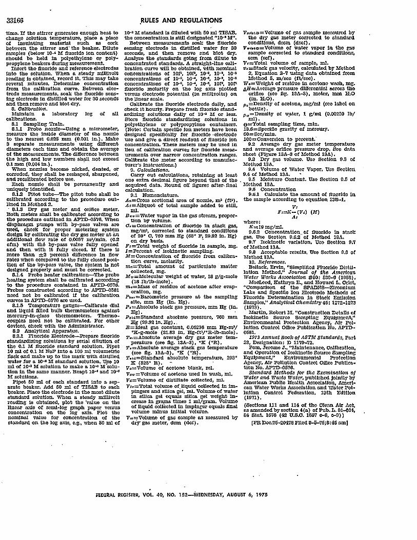
33166
time. If the stirrer generates enough heat tochange solution temperature, place a pieceof insulating material such as corkbetween the stirrer and' the beaker. Dilutesamples (below 10-' M fluoride ion content)should be held in polyethylene or poly-propylene beakers during measurement.
Insert the fluoride and reference electrodesinto the solution. When a steady millivoltreading is obtained, record it. This may takeseveral minutes. Determine concentrationfrom the calibration curve. Between elec-trode measurements, soak the fluoride sens-ing electrode in distilled water for 30 secondsand then remove and blot dry.
8. Calibration.Maintain a laboratory log of all
calibrations.8.1 Sampling Train.8.1.1 Probe nozzle-Using a micrometer,
measure the inside diameter of the nozzleto the nearest 0.025 mm (0.001 In.). Make3 separate measurements using differentdiameters each time and obtain the averageof the measurements. The difference betweenthe high and low numbers shall not exceed0.1 mm (0.004 in.).
When nozzles become nicked, dented, orcorroded, they shall be reshaped, sharpened,and recallbrated before use.
Each nozzle shall be permanently anduniquely identified.
8.12 Pitot tube-The pitot tube shall becalibrated according to the procedure out-lined in Method 2., 8.1.3 Dry gas meter and orifice meter.Both meters shall be calibrated according tothe procedure outlined in APTD-0576. Whendiaphragm pumps with by-pass valves areused, check for proper metering systemdesign by calibrating the dry gas meter at anadditional flow rate of 0.0057 m3/min. (0.2cfm) with th6 by-pass valve fully openedand then with it fully closed. If there ismore than __2 percent difference In flowrates when compared to the fully closed posi-tion of the by-pass valve, the system is notdesigned properly and must be corrected.
8.1.4 Probe heater calibration-The probeheating system shall be calibrated accordingto the procedure contained in APTD-0576.Probes constructed according to APTD-0581need not be calibrated if the calibrationcurves In APTD-0576 are used.
8.1.5 Temperature gauges--Calibrate dialand liquid filled bulb thermometers againstmercury-in-glass thermometers. Thermo-couples need not be calibrated. For otherdevices, check with the Administrator.
8.2 Analytical Apparatus.8.2.1 Fluoride Electrode-Prepare fluoride
standardizing solutions by serial dilution ofthe 0.1 M fluoride standard solution. Pipet10 ml of 0.1 M NaF into a 100 ml volumetricflask and make up to the mark with distilledwater for a 10-2 M standard solution. Use 10ml of 10-2 M solution to make a 10- 3
AT solu-tion In the same manner. Reapt 10-' and 10 -6M solutions.
Pipet 50 ml of each standard into a sep-arate beaker. Add 50 ml of TISAB to eachbeaker. Place the electrode in the most dilutestandard solution. When a steady millivoltreading Is obtained, plot the 'value on thelinear axis of semi-log graph paper versusconcentration on the log axis. Plot thenominal value for concentration of thestandard on the log axis, e.g., when 50 ml of
RULES AND REGULATIONS
10-2 M standard is diluted with 50 ml TISAB,the concentration is still designated "10-2 M".
Between measurements soak the fluoridesensing electrode in distilled water for 30seconds, and then remove and blot dry.Analyze the standards going from dilute toconcentrated standards. A straight-line cali-bration curve will be obtained, with nominalconcentrations of 10fl, 10fl, 10-3, 10-2, 10-1concentrations of 10-, 10- , 10-3, 10-2, 10-1concentrations of 10-r, 10-', 10-', lOf, 10Vfluoride molarity on the log axis plottedversus electrode potential (in millivolts) onthe linear scale.
Calibrate the fluoride electrode daily, andcheck it hourly. Prepare fresh fluoride stand-ardizing solutions daily of 10-' M or less.Store fluoride standardizing solutions inpolyethylene or polypropylene containers.(Note: Certain specific ion meters have beendesigned specifically for fluoride -electrodeuse and give a direct readout of fluoride ionconcentration. These meters may be used inlieu of calibration curves for fluoride meas-urements over narrow concentration ranges.Calibrate the meter according to manufac-turer's instructions.)
9. Calculations.Carry out calculations, retaining at least
one extra decimal figure beyond that of theacquired data. Round off figures after-finalcalculation.
9.1 Nomenclature.A.=Cross sectional area of nozzle, m7 (ft).At=Aliquot of total sample added to still,
ml.B..=Water vapor In the gas stream, propor-
tion by volume.0.=Concentration of fluoride in stack gas,
mg/m3, corrected to standard conditionsof 20' C, 760 mm Hg (680 F, 29.92 in. Hg)on dry basis.
Ft=Total weight of fluoride in sample, mg.I=Percent of lsokinetic sampling.M=Concentration of fluoride from calibra-
tion curve, molarlty.m ,=Total amount of particulate matter
collected, mg.M.=Molecular weight of water, 18 g/g-mole
(18 lb/lb-mole).in.=Mass of residue of acetone after evap-
oration, mg.P.,r=Barometric pressure at the sampling
site, mm Hg (in. Hg).P.=Absolute stack gas pressure, mm Hg (in.
Hg).Ptt=Standard absolute pressure, 760 mm
Hg (29.92 in. Hg).R=Ideal gas constant, 0.06236 mmn Hg-m'/
*K-g-mole (21.83 in. Hg-ft3/°R-lb-mole).T.=Absolute average dry gas meter tem-
perature (see fig. 13A-3), °K (°R).T,=Absolute average stack gas temperature
(see fig. 13A-3), 'K ('R).Ttd=Standard absolute temperature, 293'
1K (528' R). -V,=Volume of acetone blank, ml.V. =Volume of acetone used In wash, ml.Vd=Volume of distillate collected, ml.Vu=Total volume of liquid collected in Im-
pingers and silica gel, nil. Volume of waterin silica gel equals silica gel weight In-crease In gramns times 1 m/gram. Volumeof liquid collected in Impinger equals finalvolume minus Initial volume.
Vm=Volume of gas sample as measured bydry gas meter, -cm (dcf).
Vr(eta)=Volumo of gas sample measured bythe dry gas meter corrected to standardconditions, dscm (dscf).
V.,(.te=Volume of water vapor in tho gassample corrected to standard conditions,scm (scf).
Vt=Total volume of samples ml.v,=Stack gas velocity, calculated by Method
2, Equation 2-7 using data obtained fromMethod 5, m/sec (ft/ec).
W.=Weight of residue in acetone wash, Mag.,&H=Average pressure differential acros the
orifice (see fig. 13A-3), meter, mm ILO(in. H 20).
p=Density of acetone, mg/ml (sco label onbottle).
p,-Density of water, 1 g/mi (0.00220 lb/
(=Total sampling time, min.13.6=Specific gravity of mercury.60=Sec/mn.100=Conversion to percent.'
9.2 Average dry gas meter temperatureand average orifice pressure drop. Se datasheet (Figure 13A-3 of Method 13A).
9.3 Dry gas volume. Use Section 9.3 ofMethod 13A.
9.4 Volume of Water Vapor. Use Section9A of Method 13A.
9.5 Moisture Content. Use Section 0.5 ofMethod 13A.
9.6 Concentration9.6.1 Calculate the amount of fluoride in
the sample according to equation 13B-1.
VtFI-=- (Vd) (M)
Aswhere:K=I9 mg/mL.9.6.2 Concentration of fluoride in staok
gas. Use Section 9.6.2 of Method 13A.9.7 Isokinetic variation. Use Section 9.7
of Method 13A.9.8 Acceptable -results. Use Section 9.0 of
Method 13A.10. Re/erences.Bellack, Ervin, "Simplified Fluoride Distil-
lation Method," Journal of the AmericanWater Works Assoolation #60: 630-0 (1958).MacLeod, Kathryn E,, and Howard L. Crist,
"Comparison of the SPADNS-ZirconiumnLake and Specific Ion Electrode Methods ofFluoride Determination In Stack EmissionSamples," Analjtical Ohemiatryj 46: 1272-1273(1973).Martin, Robert M. "Construction Details of
Isokinetic Source Sampling Equipment,"Environmental Protection Agency, Air Pol-lution Control Office Publication No. APTD-0581.
1973 Annual Book o1 ASTM Standards, Part23, Designation: D 1179-72.
Pom, Jerome J., "Maintenance, Calibration,and Operation of Isokinetic Source SamplingEquipment," Environmental ProtectionAgency, Air Pollution Control Office Publica-tion No. APTD-0576.
Standard Methods for the Examination ofWater and Waste Water, published jointly byAmerican Public Health Association, Ameri-can Water Works Association and Water Pol-lution Control Federation, 13th Edition(1971).
(Sections 1U1 and 114 of the Clean Air Act,as amended by section 4(a) of Pub. L, 91-04,84 Stat. 1678 (42 U.S.C. 1857 c-0, o-9))
[FR Doc.75-20478 Filed 8-5-758:46 am]
FEDERAL REGISTER, VOL 40, NO. 152-EDNESDAY, AUGUST 6, 1975