07_high-resolution xrd
TRANSCRIPT

8/7/2019 07_High-Resolution XRD
http://slidepdf.com/reader/full/07high-resolution-xrd 1/51
High-Resolution XRD

8/7/2019 07_High-Resolution XRD
http://slidepdf.com/reader/full/07high-resolution-xrd 2/51
What is thin film/layer?
Material so thin that its characteristics are dominated primarily by twodimensional effects and are mostly different than its bulk propertiesSource: semiconductorglossary.com
Material which dimension in the out-of-plane direction is much smallerthan in the in-plane direction.
A thin layer of something on a surface
Source: encarta.msn.com

8/7/2019 07_High-Resolution XRD
http://slidepdf.com/reader/full/07high-resolution-xrd 3/51
Epitaxial Layer
A single crystal layer that has been deposited or grown on a crystallinesubstrate having the same structural arrangement.Source: photonics.com
A crystalline layer of a particular orientation on top of another crystal,where the orientation is determined by the underlying crystal.
Homoepitaxial layer
the layer and substrate are the same material and possess the same lattice parameters.
Heteroepitaxial layerthe layer material is different than the substrate and usually has different lattice parameters.

8/7/2019 07_High-Resolution XRD
http://slidepdf.com/reader/full/07high-resolution-xrd 4/51
Accessible Information to X-rayDiffraction
Definition for structural types
Structure Type Definition
Perfect epitaxial Single crystal in perfect registry with the substrate that is also perfect.
Nearly perfect epitaxialSingle crystal in nearly perfect registry with the substrate that is alsonearly perfect.
Textured epitaxialLayer orientation is close to registry with the substrate in both in-plane and out-of-plane directions. Layer consists of mosaic blocks.
Textured polycrystallineCrystalline grains are preferentially oriented out-of-plane but randomin-plane. Grain size distribution.
Perfect polycrystalline Randomly oriented crystallites similar in size and shape.
Amorphous Strong interatomic bonds but no long range order.
P.F. Fewster “X-ray Scattering from Semiconductors”

8/7/2019 07_High-Resolution XRD
http://slidepdf.com/reader/full/07high-resolution-xrd 5/51
Accessible Information to X-ray Diffraction
Defects that are common in epilayer structures

8/7/2019 07_High-Resolution XRD
http://slidepdf.com/reader/full/07high-resolution-xrd 6/51
Crystalline state of the layers:
Epitaxial (coherent with the substrate, relaxed)
Polycrystalline (random orientation, preferred orientation)
Amorphous
Crystalline quality
Strain state (fully or partially strained, fully relaxed)
Defect structure Chemical composition
Thickness
Surface and/or interface roughness
What we want to know about thin films?

8/7/2019 07_High-Resolution XRD
http://slidepdf.com/reader/full/07high-resolution-xrd 7/51
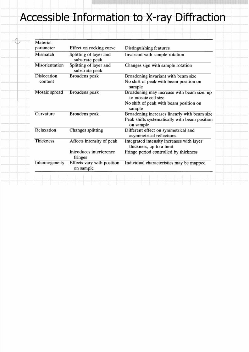
Accessible Information to X-rayDiffraction
Structural parameters that characterize various material types
× – parameters that have meaning? – parameters that could have meaning
Thickness Composition Relaxation DistortionCrystalline
sizeOrientation Defects
Perfect epitaxy × × ×Nearly perfect epitaxy × × ? ? ? × ×Textured epitaxy × × × × × × ×Textured polycrystalline × × ? × × × ?
Perfect polycrystalline × × × × ?
Amorphous × ×
8/7/2019 07_High-Resolution XRD
http://slidepdf.com/reader/full/07high-resolution-xrd 8/51
Accessible Information to X-ray Diffraction

8/7/2019 07_High-Resolution XRD
http://slidepdf.com/reader/full/07high-resolution-xrd 9/51

8/7/2019 07_High-Resolution XRD
http://slidepdf.com/reader/full/07high-resolution-xrd 10/51
(000)
(00l)
(100)
(10l)
(200)
(20l)
Tetragonal: aII
L= a
S, a⊥
L> a
S
Cubic
Strained Layer
Tetragonaldistortion

8/7/2019 07_High-Resolution XRD
http://slidepdf.com/reader/full/07high-resolution-xrd 11/51
Cubic
Cubic
Cubic
Tetragonal
ReciprocalSpace
(000) (000)
(00l) (00l)
(hkl) (hkl)
aL > aS
Perfect Layers: Relaxed and Strained

8/7/2019 07_High-Resolution XRD
http://slidepdf.com/reader/full/07high-resolution-xrd 12/51
Mismatch
Consider two materials with the same space group, same atomicarrangements, but slightly different lattice parameters and elasticparameters.
aL
aL=aS
aS
aS
aS
aS
cL
aL
Beforedeposition
Afterdeposition
0
0
L
z
L
z
L
z zz
d
d d −==⊥ ε ε
8/7/2019 07_High-Resolution XRD
http://slidepdf.com/reader/full/07high-resolution-xrd 13/51
Beforedeposition
After
depositionRL
R
LL
RL
R
LL
zz d
d d
a
aa −=
−==
⊥⊥
⊥ ε ε
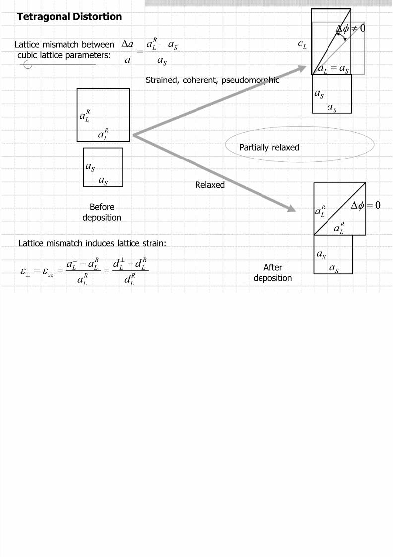
Tetragonal Distortion
Lattice mismatch betweencubic lattice parameters:
S
S
R
L
a
aa
a
a −=
∆
Lattice mismatch induces lattice strain:
R
La
R
La
S aS a
Lc
S L aa =
S aS a
RLa
R
La
S aS a
0≠∆φ
0=∆φ
Relaxed
Strained, coherent, pseudomorphic
Partially relaxed
8/7/2019 07_High-Resolution XRD
http://slidepdf.com/reader/full/07high-resolution-xrd 14/51
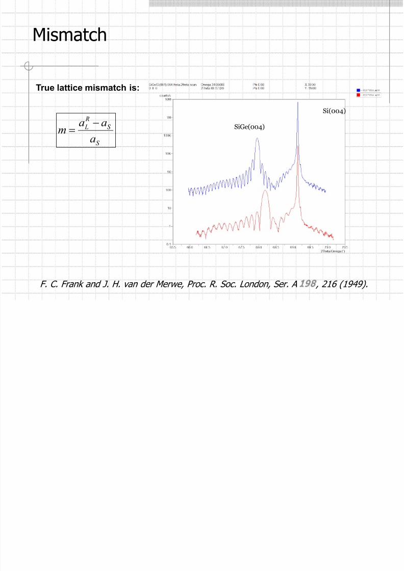
Mismatch
S
S
R
L
a
aam
−=
Si(004)
SiGe(004)
True lattice mismatch is:
F. C. Frank and J. H. van der Merwe, Proc. R. Soc. London, Ser. A 198 , 216 (1949).

8/7/2019 07_High-Resolution XRD
http://slidepdf.com/reader/full/07high-resolution-xrd 15/51
Mismatch
Single layer AlGaAs on GaAs substrate.
Specimen angle (arc sec)
Intensity (cps)
δθ

8/7/2019 07_High-Resolution XRD
http://slidepdf.com/reader/full/07high-resolution-xrd 16/51
Mismatch
The peak separation between substrate and layer is related to the change of interplanar spacing normal to the substrate through the equation:
θ δθ δ
cot−=d
d
If it is 00l reflection then the “experimental x-ray mismatch”:
d
d
a
am
δ δ ==*
True lattice mismatch is:
s
s
R
l
a
aam
−=
then
+
−=
ν
ν
1
1*mm
ν – Poisson ratio 2
*
3
1
mm ≈
≈ν

8/7/2019 07_High-Resolution XRD
http://slidepdf.com/reader/full/07high-resolution-xrd 17/51
CompositionVegard's law a law stating that the lattice parameters of substitutional solid solutions vary linearly
between the values for the components and where the composition is expressed inatomic percentage.
BABAaxxaa
xx
)1(1
−+=−
For SiGe:
( ) 112007.0)1(2
1
−−+−+=−
xaxxaaSiGeSiGe
xx

8/7/2019 07_High-Resolution XRD
http://slidepdf.com/reader/full/07high-resolution-xrd 18/51
Substrate misorientation
Substrates are often specified at some angle from (001) or (111).
This may need to be verified.
2
21 ω ω ϕ
−=
Rotation of the surface plane through 180o between measurements
If we do measurements at 0o and 180o to get ϕ0 and at 90o and 270o to get ϕ90, thenmaximum ϕmax is given by:
=
+=
0
90max
90
2
0
2
max
tan
tanarctan
tantanarctan
ϕ
ϕ φ
ϕ ϕ ϕ

8/7/2019 07_High-Resolution XRD
http://slidepdf.com/reader/full/07high-resolution-xrd 19/51
Layer TiltIf the layer is tilted relative to the substrate then this will result in a shift of thelayer peak relative to that of the substrate.
This is not connected with the composition.
( )2
1800 δθ δθ δθ
+= in-plane sample rotation
We do not know direction of the maximum tilt, φ 0
( )
( ) 00180
0090
00
cos180cos
sin90cos
cos
φ β φ β
φ β φ β
φ β
−=+=∆
−=+=∆=∆
then0
900tan ∆
∆
=φ
True splitting mismatch:
β – tilt angle, α – rotation angleDisplacement of a layer peak: α β cos

8/7/2019 07_High-Resolution XRD
http://slidepdf.com/reader/full/07high-resolution-xrd 20/51
Relaxation
The problems occur when the elastic parameters are incapable of accommodating the distortions necessary for perfect epitaxy.
8/7/2019 07_High-Resolution XRD
http://slidepdf.com/reader/full/07high-resolution-xrd 21/51
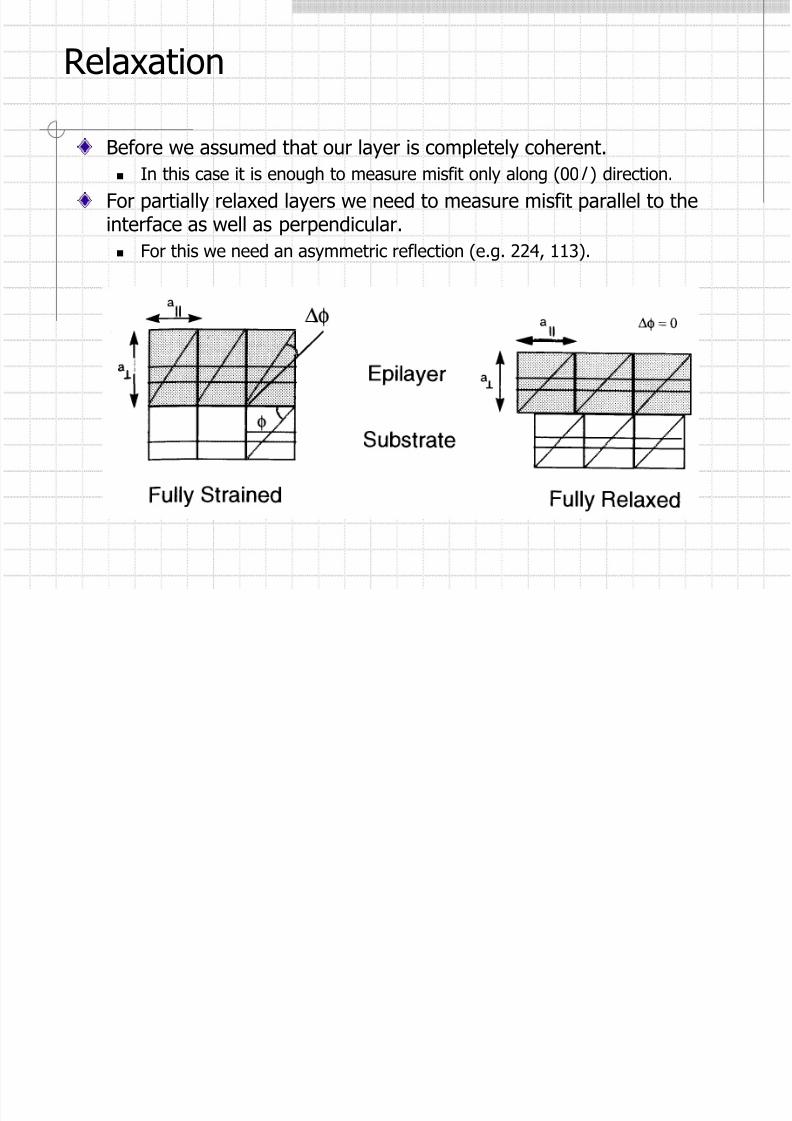
Relaxation
Before we assumed that our layer is completely coherent. In this case it is enough to measure misfit only along (00 l ) direction.
For partially relaxed layers we need to measure misfit parallel to theinterface as well as perpendicular.
For this we need an asymmetric reflection (e.g. 224, 113).
8/7/2019 07_High-Resolution XRD
http://slidepdf.com/reader/full/07high-resolution-xrd 22/51
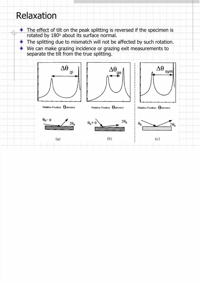
Relaxation
The effect of tilt on the peak splitting is reversed if the specimen is
rotated by 180o about its surface normal.The splitting due to mismatch will not be affected by such rotation.
We can make grazing incidence or grazing exit measurements toseparate the tilt from the true splitting.

8/7/2019 07_High-Resolution XRD
http://slidepdf.com/reader/full/07high-resolution-xrd 23/51
Relaxation
The resulting measured splittings are now different between these twogeometries:
δφ δθ θ +=∆ i – grazing incidence
– grazing exitδφ δθ θ −=∆ e
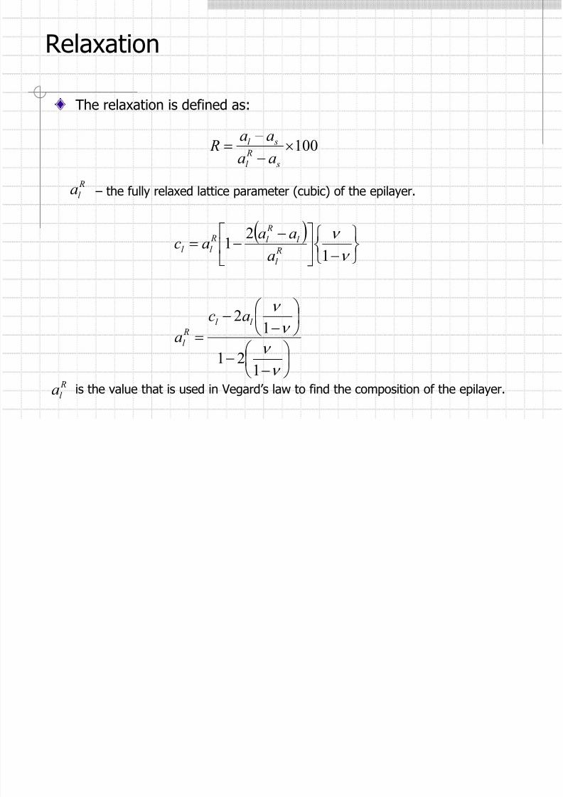
We need to know the lattice parameter of the layer parallel and perpendicular tothe substrate: al, bl, and cl. From these we may calculate the relaxation and thefully relaxed lattice parameter as.
Consider al = bl (tetragonal distortion).
δφ φ φ
δθ θ θ
+=
+=
sl
sl
φ – angle between reflecting plane and the surface
8/7/2019 07_High-Resolution XRD
http://slidepdf.com/reader/full/07high-resolution-xrd 24/51
Relaxation
θ λ sin2
1
2
2
2
22
2
d
c
l
a
k h
d l l hkl
=
++
=
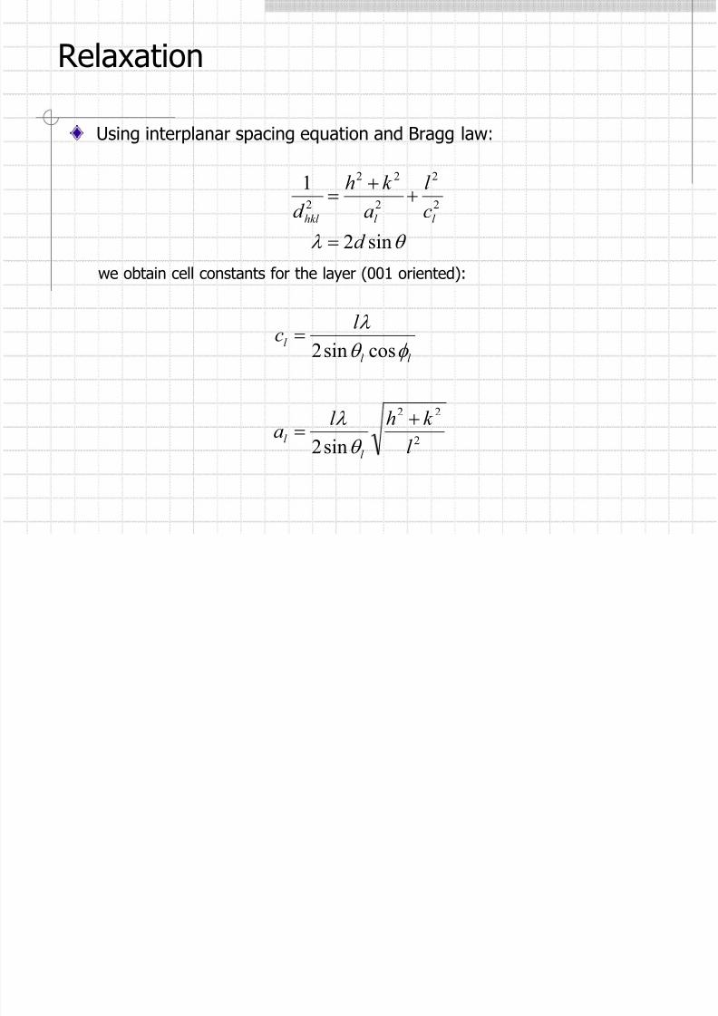
Using interplanar spacing equation and Bragg law:
we obtain cell constants for the layer (001 oriented):
2
22
sin2
cossin2
l
k hl a
l c
l
l
l l
l
+=
=
θ
λ
φ θ
λ
8/7/2019 07_High-Resolution XRD
http://slidepdf.com/reader/full/07high-resolution-xrd 25/51

8/7/2019 07_High-Resolution XRD
http://slidepdf.com/reader/full/07high-resolution-xrd 26/51
Relaxation
( )
2
222
222
cottan
tancosec
l a
l k hcl
ck ha
s
l
−
+−∆
++−
+=
φ θ θ
θ φ
If we know that (001) planes of layer and substrate remain parallel, wecan derive the relaxation from just symmetric and the grazingincidence reflections (no grazing exit).
Important in quality control to save measurement time.
The symmetric reflection provides cl.
valid if δθ and δφ are small.

8/7/2019 07_High-Resolution XRD
http://slidepdf.com/reader/full/07high-resolution-xrd 27/51
Determination of Thickness
Interference fringes observedin the scattering pattern, dueto different optical paths of the x-rays, are related to thethickness of the layers.
( )( )
( )
1
21
21
21
cos2~
sinsin2 ω ω
λ
ω ω
λ
∆
−
−
−=
nnnnt

8/7/2019 07_High-Resolution XRD
http://slidepdf.com/reader/full/07high-resolution-xrd 28/51
Determination of Thickness
Interference fringesobserved in thescattering pattern,due to differentoptical paths of thex-rays, are related to
the thickness of thelayers.
( )
( )21
21
sinsin2 ω ω
λ
−
−=
nnt
Substrate Layer Separation
S-peak: L-peak: Separation:Omega(°) 34.5649 Omega(°) 33.9748 Omega(°) 0.590172Theta(°) 69.1298 2Theta(°) 67.9495 2Theta(°) 1.18034
Layer Thickness
Mean fringe period (°): 0.09368Mean thickness (um): 0.113 ± 0.003
2Theta/Omega (°) Fringe Period (°) Thickness (um)_____________________________________________________________________________
66.22698 - 66.32140 0.09442 0.11163766.32140 - 66.41430 0.09290 0.11352866.41430 - 66.50568 0.09138 0.11548166.50568 - 66.59858 0.09290 0.113648
66.59858 - 66.69300 0.09442 0.11187866.69300 - 66.78327 0.09027 0.117079

8/7/2019 07_High-Resolution XRD
http://slidepdf.com/reader/full/07high-resolution-xrd 29/51
Area Homogeneity
Whatever the crystal growers claim, epitaxial layers are not uniformacross their area!
1% consistency is good.
3×3 grid
9×9 gridSurface mesh plot showing the variation of In
content in an InAlAs layer on GaAs

8/7/2019 07_High-Resolution XRD
http://slidepdf.com/reader/full/07high-resolution-xrd 30/51
Relaxed SiGe on Si(001)
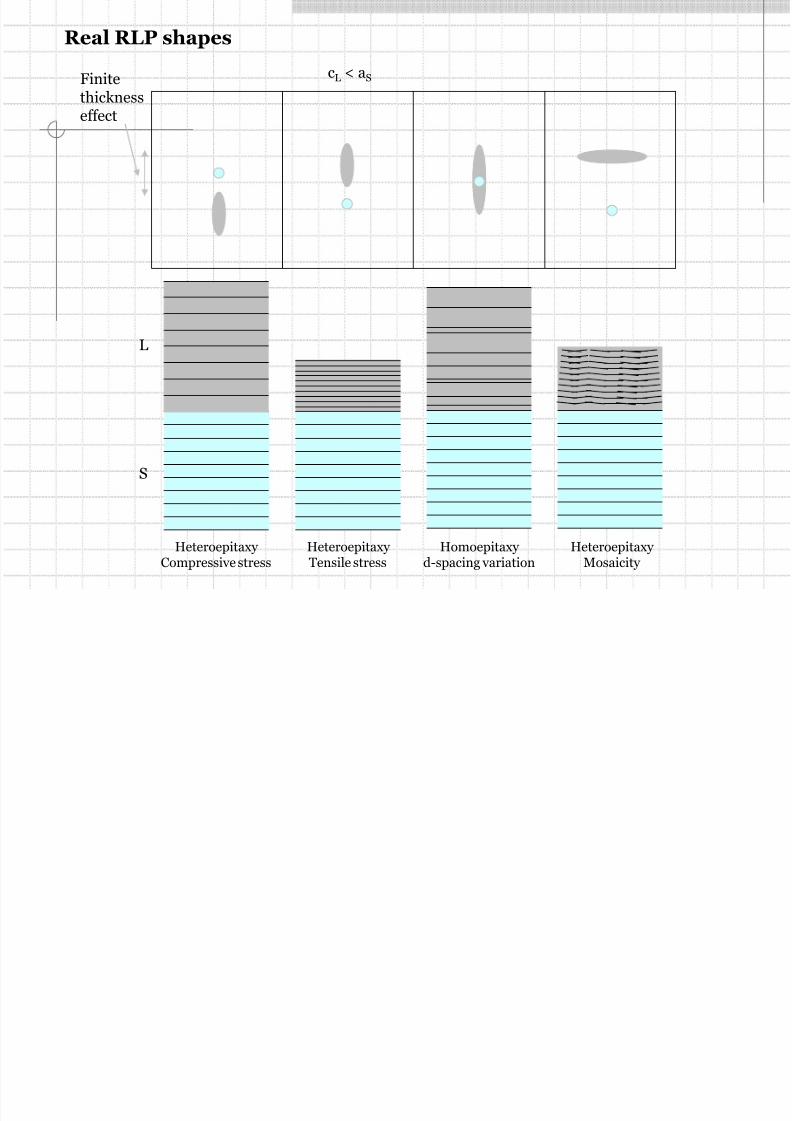
Shape of the RLP mightprovide much moreinformation
8/7/2019 07_High-Resolution XRD
http://slidepdf.com/reader/full/07high-resolution-xrd 31/51
Heteroepitaxy Compressive stress
L
S
Heteroepitaxy Tensile stress
Homoepitaxy d-spacing variation
Heteroepitaxy Mosaicity
Finitethicknesseffect
cL < aS
Real RLP shapes
8/7/2019 07_High-Resolution XRD
http://slidepdf.com/reader/full/07high-resolution-xrd 32/51
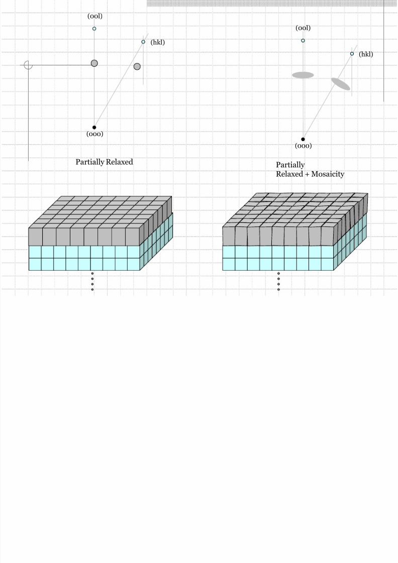
(000)
(00l)
(hkl)
Partially Relaxed + Mosaicity
(000)
(00l)
(hkl)
Partially Relaxed

8/7/2019 07_High-Resolution XRD
http://slidepdf.com/reader/full/07high-resolution-xrd 33/51
Reciprocal Space (revisited)
The Ewald sphere construction for a set of planes at the correctBragg angle
θ λ θ λ
sin22
1
2
1sin
1 *
hkl
hkl
hkl d d
=→=== dOC
*
hkl dOB =

8/7/2019 07_High-Resolution XRD
http://slidepdf.com/reader/full/07high-resolution-xrd 34/51
Reciprocal Space (revisited)
Bragg’s law expressed in vector notation.
Vectors (s – s0) and d*hkl are parallel and the ratio of the moduli is λ.
( ) *
hkl d
ss0 =
−
λ
8/7/2019 07_High-Resolution XRD
http://slidepdf.com/reader/full/07high-resolution-xrd 35/51
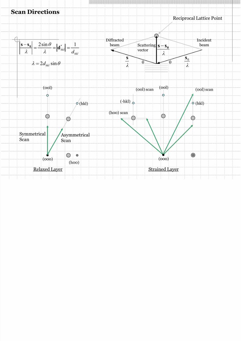
(000)
(00l)
(hkl)
SymmetricalScan
AsymmetricalScan
(000)
(00l)
(hkl)
(00l) scan
(h00) scan
(h00)
(-hkl)
(00l) scan
Relaxed Layer Strained Layer
Scan Directions
Incident
beam
Diffracted
beam Scatteringvector
hkl
hkl
d
1sin2 * ===− dss 0
λ
θ
λ λ
0ss −
λ
s
λ
0sθθθ λ sin2 hkl d =
Reciprocal Lattice Point
8/7/2019 07_High-Resolution XRD
http://slidepdf.com/reader/full/07high-resolution-xrd 36/51
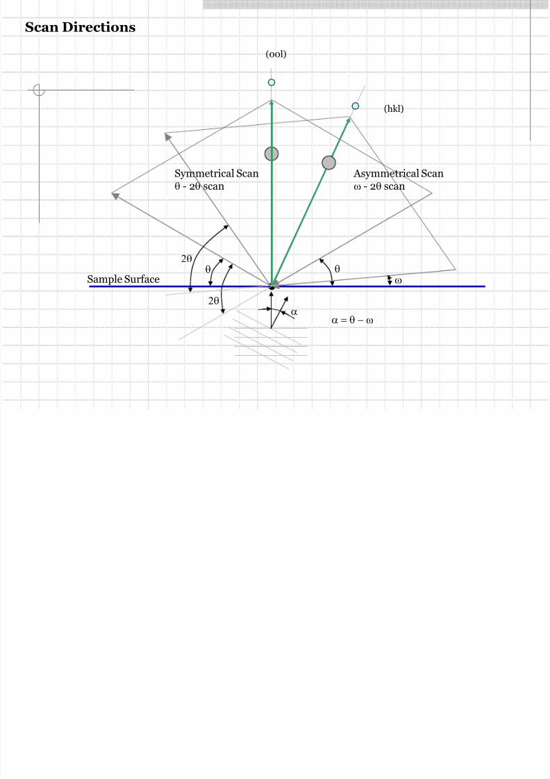
Sample Surface
(00l)
Symmetrical Scanθ - 2θ scan
θθ
2θ
(hkl)
Asymmetrical Scanω - 2θ scan
αα = θ − ω
ω
2θ
Scan Directions

8/7/2019 07_High-Resolution XRD
http://slidepdf.com/reader/full/07high-resolution-xrd 37/51

8/7/2019 07_High-Resolution XRD
http://slidepdf.com/reader/full/07high-resolution-xrd 38/51
(00l)
(hkl)
Symmetricalω - 2θ scan
Asymmetricalω - 2θ scan
Sample Surface
2θ scan
Scan directions
ω scanω scan
8/7/2019 07_High-Resolution XRD
http://slidepdf.com/reader/full/07high-resolution-xrd 39/51
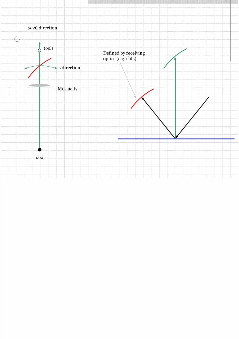
(000)
(00l)
ω direction
ω-2θ direction
Defined by receivingoptics (e.g. slits)
Mosaicity

8/7/2019 07_High-Resolution XRD
http://slidepdf.com/reader/full/07high-resolution-xrd 40/51
(000)
(00l)
ω direction
ω-2θ direction
Symmetrical Scan
receivingslit
analyzercrystal
mosaicity
receivingslit
analyzercrystal
d-spacing variation
8/7/2019 07_High-Resolution XRD
http://slidepdf.com/reader/full/07high-resolution-xrd 41/51
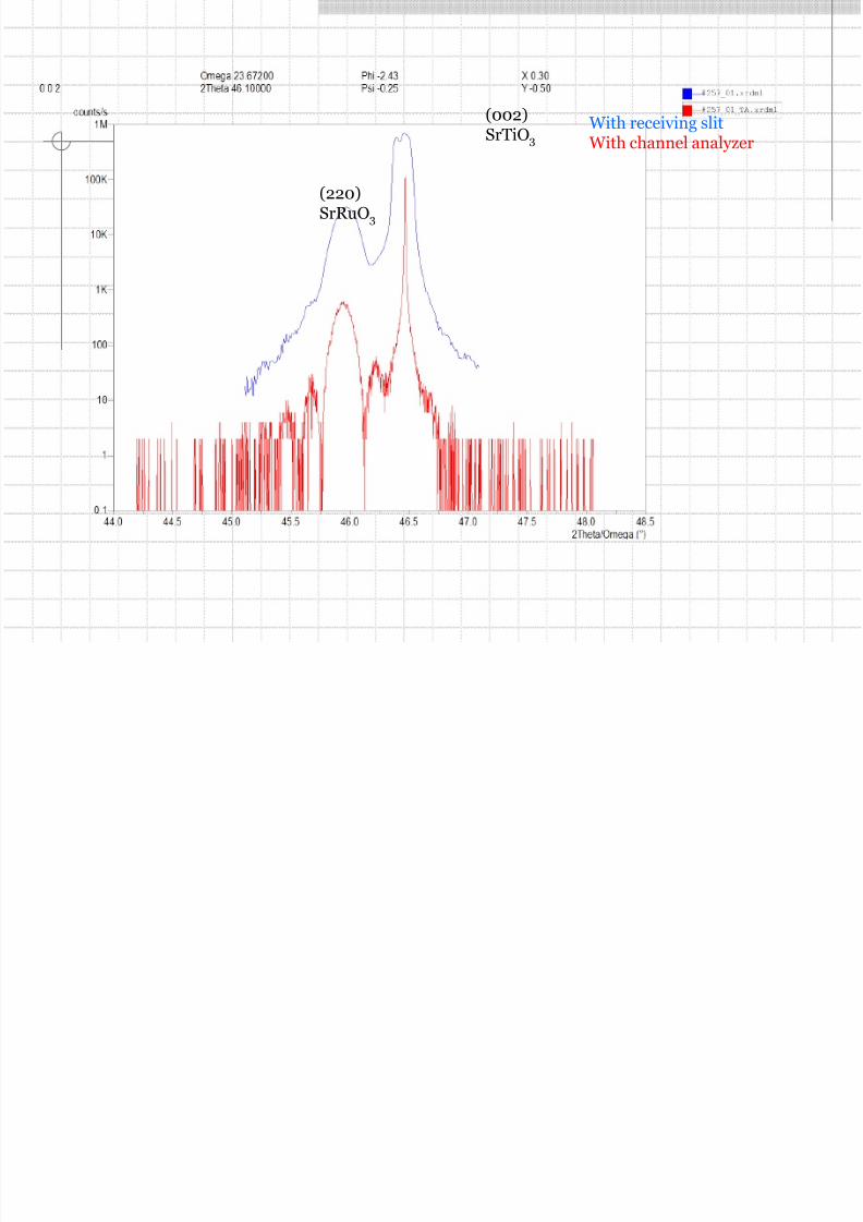
With receiving slitWith channel analyzer
(002)SrTiO3
(220)SrRuO3

8/7/2019 07_High-Resolution XRD
http://slidepdf.com/reader/full/07high-resolution-xrd 42/51

8/7/2019 07_High-Resolution XRD
http://slidepdf.com/reader/full/07high-resolution-xrd 43/51

8/7/2019 07_High-Resolution XRD
http://slidepdf.com/reader/full/07high-resolution-xrd 44/51
Reciprocal Space (revisited)

8/7/2019 07_High-Resolution XRD
http://slidepdf.com/reader/full/07high-resolution-xrd 45/51
Reciprocal Space

8/7/2019 07_High-Resolution XRD
http://slidepdf.com/reader/full/07high-resolution-xrd 46/51
Reciprocal Space
ω-scan is in the direction of an arc centered on the origin2θ-scan is an arc along Ewald sphere circumferenceω-2θ scan is always strait line pointing away from the origin of the reciprocal space

8/7/2019 07_High-Resolution XRD
http://slidepdf.com/reader/full/07high-resolution-xrd 47/51
High-Resolution Diffractometry
The geometry of the Bragg-Brentano diffractometer.

8/7/2019 07_High-Resolution XRD
http://slidepdf.com/reader/full/07high-resolution-xrd 48/51
High-Resolution Diffractometry
Schematic of high resolution double-axis instrument

8/7/2019 07_High-Resolution XRD
http://slidepdf.com/reader/full/07high-resolution-xrd 49/51
High-Resolution Diffractometry
The geometry of the double crystal diffractometer.
8/7/2019 07_High-Resolution XRD
http://slidepdf.com/reader/full/07high-resolution-xrd 50/51
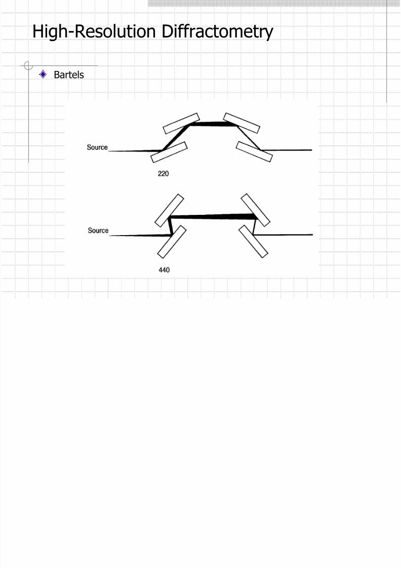
High-Resolution Diffractometry
Bartels

8/7/2019 07_High-Resolution XRD
http://slidepdf.com/reader/full/07high-resolution-xrd 51/51
Incident Beam:
X-ray Hybrid Monochromator
High Resolution Geometry
Mirror
Sample
F
θ = 0.5o
θ < 19 arcsec
Parabola
Ge(220) Crystal