07-03 mini project - copy edited
TRANSCRIPT

CONGESTION CONTROL USING NBP
SPHOORTHY ENGINEERING COLLEGE Page 0

CONGESTION CONTROL USING NBP
1. Introduction
Congestion control concerns controlling traffic entry into a network so as to avoid
congestion collapse by attempting to avoid oversubscription of any of the processing or
link capabilities of the intermediate nodes and networks and taking resource reducing steps, such as
reducing the rate of sending packets. It should not be confused with flow control, which prevents the
sender from overwhelming the receiver.
The network excellent scalability and robustness result in part from the end-to-end nature of
network congestion control. End-to-end congestion control algorithms alone, however, are unable to
prevent the congestion collapse and unfairness created by applications that are unresponsive to
network congestion.
To address these maladies, we propose and investigate a novel congestion-avoidance
mechanism called Congestion Free Router (CFR). CFR entails the exchange of feedback between
routers at the borders of a network in order to detect and restrict unresponsive traffic flows before
they enter the network, thereby preventing congestion within the network.
The fundamental philosophy behind the Internet is expressed by the scalability argument: no
protocol, mechanism, or service should be introduced into the Internet if it does not scale well.
1.1 Purpose
Congestion Control Based On NBP is a networking application which
can be implemented on java platform. Its provides reliable communication between the users in the
same organization within the same LAN. This project enables the user to send text messages i.e. chat
with all the users without facing the congestion problems and delay in sending messages.
1.2 Document Conventions
In this document, we have used the following format:
SPHOORTHY ENGINEERING COLLEGE Page 1
CONGESTION CONTROL USING NBP
For Main Headings:
Font : 16pt
Font-face : Times New Roman
Font-weight: Bold, Italic
For Headings:
Font : 14pt
Font-face : Times New Roman
Font-weight : Bold, Italic
For Sub Headings:
Font : 12pt
Font-face : Times New Roman
Font-weight : Bold, Italic
For Content:
Font : 12pt
Font-face : Times New Roman
Font-weight : Normal
NBP: Network Based Protocols
CFR: Control Free Router
LAN: Local Area Network
TCP: Transmission Control Protocol
IP : Internet protocol
1.3 Scope
CFR entails the exchange of feedback between routers at the borders of a network in order to
detect and restrict unresponsive traffic flows before they enter the network, thereby preventing
congestion within the network.
SPHOORTHY ENGINEERING COLLEGE Page 2

CONGESTION CONTROL USING NBP
The main scope of the project is to:
Network Border Patrol entails the exchange of feedback between routers at the borders of a
network.
Restrict unresponsive traffic flows.
Prevents congestion within the network.
1.4 Benefits
Fast transmission
Data backup
Reduces delay
Controls congestion within the network
Standalone application
Easy to use
Saves the messages automatically
Reliable data transmission within the LAN
Every user in an organization can interact with each other
2. System Analysis
SPHOORTHY ENGINEERING COLLEGE Page 3

CONGESTION CONTROL USING NBP
2.1 Existing System
As a result of its strict adherence to end-to-end congestion control, the current Internet
suffers from two maladies:
Congestion collapse from undelivered packets
unfair allocations of bandwidth between competing traffic flows.
Congestion collapse from undelivered packets — arises when packets that are dropped
before reaching their ultimate continually consume bandwidth destinations.
Unfair bandwidth allocation to competing network flows—arises in the Internet for a
variety of reasons, one of which is the existence of applications that do not respond properly to
congestion. Adaptive applications (e.g., TCP-based applications) that respond to congestion by
rapidly reducing their transmission rates are likely to receive unfairly small bandwidth allocations
when competing with unresponsive applications. The Internet protocols themselves can also
introduce unfairness. The TCP algorithm, for instance, inherently causes each TCP flow to receive a
bandwidth that is inversely proportional to its round-trip time [6]. Hence, TCP connections with
short round-trip times may receive unfairly large allocations of network bandwidth when compared
to connections with longer round-trip times.
The impact of emerging streaming media traffic on traditional data traffic is of growing
concern in the Internet community. Streaming media traffic is unresponsive to the congestion in a
network, and it can aggravate congestion collapse and unfair bandwidth allocation.
2.2 Proposed System
To address the maladies of congestion collapse we introduce and investigate a novel Internet
traffic control protocol called Congestion Free Router (CFR). The basic principle of CFR is to
compare, at the borders of a network, the rates at which packets from each application flow are
entering and leaving the network. If a flow’s packets are entering the network faster than they are
SPHOORTHY ENGINEERING COLLEGE Page 4

CONGESTION CONTROL USING NBP
leaving it, then the network is likely buffering or, worse yet, discarding the flow’s packets. In other
words, the network is receiving more packets than it is capable of handling. CFR prevents this
scenario by “patrolling” the network’s borders, ensuring that each flow’s packets do not enter the
network at a rate greater than they are able to leave the network. This patrolling prevents congestion
collapse from undelivered packets, because unresponsive flow’s otherwise undeliverable packets
never enter the network in the first place.
Although CFR is capable of preventing congestion collapse and improving the fairness of
bandwidth allocations, these improvements do not come for free. CFR solves these problems at the
expense of some additional network complexity, since routers at the border of the network are
expected to monitor and control the rates of individual flows in CFR.
CFR also introduces added communication overhead, since in order for an edge outer to
know the rate at which its packets are leaving the network, it must exchange feedback with other
edge routers.
Unlike some existing approaches trying to solve congestion collapse, however, CFR’s added
complexity is isolated to edge routers; routers within the core of the network do not participate in the
prevention of congestion collapse. Moreover, end systems operate in total ignorance of the fact that
CFR is implemented in the network, so no changes to transport protocols are necessary at end
systems.
SPHOORTHY ENGINEERING COLLEGE Page 5

CONGESTION CONTROL USING NBP
3. Requirements
3.1 Functional Requirements
Advanced Java
Socket Programming
File Concepts
Threads
Batch files
3.2 Software Requirements
Java1.4 or More
Swings
Windows 98
3.3 Hardware Requirements
Hard disk : 40 GB
RAM : 128mb
Processor : Pentium 4
Monitor : 15” color monitor
Floppy drive : 1.44 MB
Mouse : HCL
CD Drive : LG 52X
4. Architecture
SPHOORTHY ENGINEERING COLLEGE Page 6

CONGESTION CONTROL USING NBP
1: Sender sends a message to receiver.
2: The sender messages are received in the form of packets, and congestion flow is monitored using traffic shaping algorithms,these are forwaded to InRouter.
3: Router accpects the packets from InRouter and forwards to OutRouter.
4: The packets are reeived from OutRouter, and congestion flow is monitored using rate monitoring algorithms.
5: From the OutRouter the messages are transmitted to destination.
5. System Design
SPHOORTHY ENGINEERING COLLEGE Page 7
CONGESTION CONTROL USING NBP
5.1 Module Specification
The various modules in the project are as follows:
Module 1: SOURCE MODULE
Module 2: INROUTERROUTER MODULE
Module 3: ROUTER MODULE
Module 4: OUTROUTERROUTER MODULE
Module 5: DESTINATION MODULE
SOURCE Module:
The task of this Module is to send the data in form of packet in to the InRouter router.
Functionalities:
Input data entities : Message to be transmitted from the source to the
destination node in the form of packet with IP address for its identification.
Algorithm : not applicable
Output : formatted packet with the required information for communicating
between the source & the destination node.
INROUTER Router Module:
An edge router operating on a flow passing into a network is called an InRouter router. CFR
prevents congestion collapse through a combination of per-flow rate monitoring at OutRouter routers
and per-flow rate control at InRouter routers. Rate control allows an InRouter router to police the
rate at which each flow’s packets enter the network. InRouter Router contains a flow classifier, per-
flow traffic shapers (e.g., leaky buckets), a feedback controller, and a rate controller.
SPHOORTHY ENGINEERING COLLEGE Page 8

CONGESTION CONTROL USING NBP
Functionalities:
Input data entities : which determine the rate of the packets.
Algorithm : Leaky bucket
Output : All the nodes in the network assigned with a unique rank.
ROUTER Module :
The task of this Module is to accept the packet from the InRouter router and send it to the
OutRouter router.
Functionalities:
Input entities : receives data neighboring nodes
and transfer into another neighboring nodes.
Algorithm : not applicable.
Output : transfer packets to neighboring nodes
OUTROUTER Router Module :
An edge router operating on a flow passing out of a network is called an OutRouter router.
CFR prevents congestion collapse through a combination of per-flow rate monitoring at OutRouter
routers and per-flow rate control at InRouter routers. Rate monitoring allows an OutRouter router to
determine how rapidly each flow’s packets are leaving the network. Rate monitored using a rate
estimation algorithm such as the Time Sliding Window (TSW) algorithm. OutRouter Router
contains a flow classifier, Rate monitor, and a feedback controller.
Functionalities:
Input data entities : which determine the rate of the packets flow in the network.
Algorithm : time sliding window and rate monitoring algorithm
Output : packets are sent to destination.
DESTINATION Module:
SPHOORTHY ENGINEERING COLLEGE Page 9

CONGESTION CONTROL USING NBP
The task of this Module is to accept the packet from the OutRouter router and stored in a file
in the Destination machine.
Functionalities:
Input data entities : message to be received from the out router to the destination node
in the form of packets with IP address.
Algorithm : not applicable
Output : formatted packets with the required information for communication
between source and destination nodes.
5.2 UML Diagrams
The Unified Modeling Language (UML) is a standard language for specifying, visualizing,
constructing, and documenting the artifacts of the software systems, as well as for business modeling
and other non-software systems. The UML represents a collection of best engineering practices that
has proven successful in the modeling of large and complex systems. The UML is very important
parts of developing object oriented software and the software development process. The UML
mostly uses graphical notations to expres the design of the software projects. Using the UML helps
project teams communicate, explore potential designs, and validate the architectural design of the
software.
Each UML diagram is designed to let developers and customers view a software system from
a different perspective and in varying degrees of abstraction. UML diagrams commonly created in
visual modeling tools include
Use Case Diagram displays the relationship among actors and the use cases.
Class Diagram models class structure and contents using design elements such as classes,
packages and objects. It also displays relationships such as containment, inheritance,
associations and multiplicities.
Interaction Diagrams
SPHOORTHY ENGINEERING COLLEGE Page 10

CONGESTION CONTROL USING NBP
Sequence Diagram displays the time sequence of the objects participating in the interaction.
This consists of the vertical dimension (time) and horizontal dimension(different objects).
Collaboration Diagram displays an interaction organized around and objects and their links
to one another. Numbers are used to show sequence of messages.
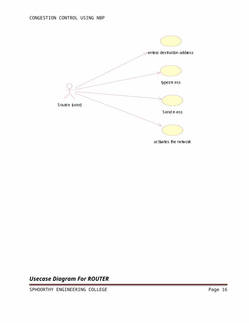
Usecase Diagram For SOURCE
SPHOORTHY ENGINEERING COLLEGE Page 11
CONGESTION CONTROL USING NBP
typer mess
Send mess
activates the network
Source (user)
enters destnation address
Usecase Diagram For ROUTER
SPHOORTHY ENGINEERING COLLEGE Page 12
CONGESTION CONTROL USING NBP
sends mess to destination
receives packets
transfers packets
stores info like IP address,mess,time,feedback
Router
sends packets to router one by one
receives packets from router application of Rate monitoring algorithm
OutRouter
splits dat into each packet of 48 bits
InRouter
application of leaky bucket algorithm,time sliding algorithm
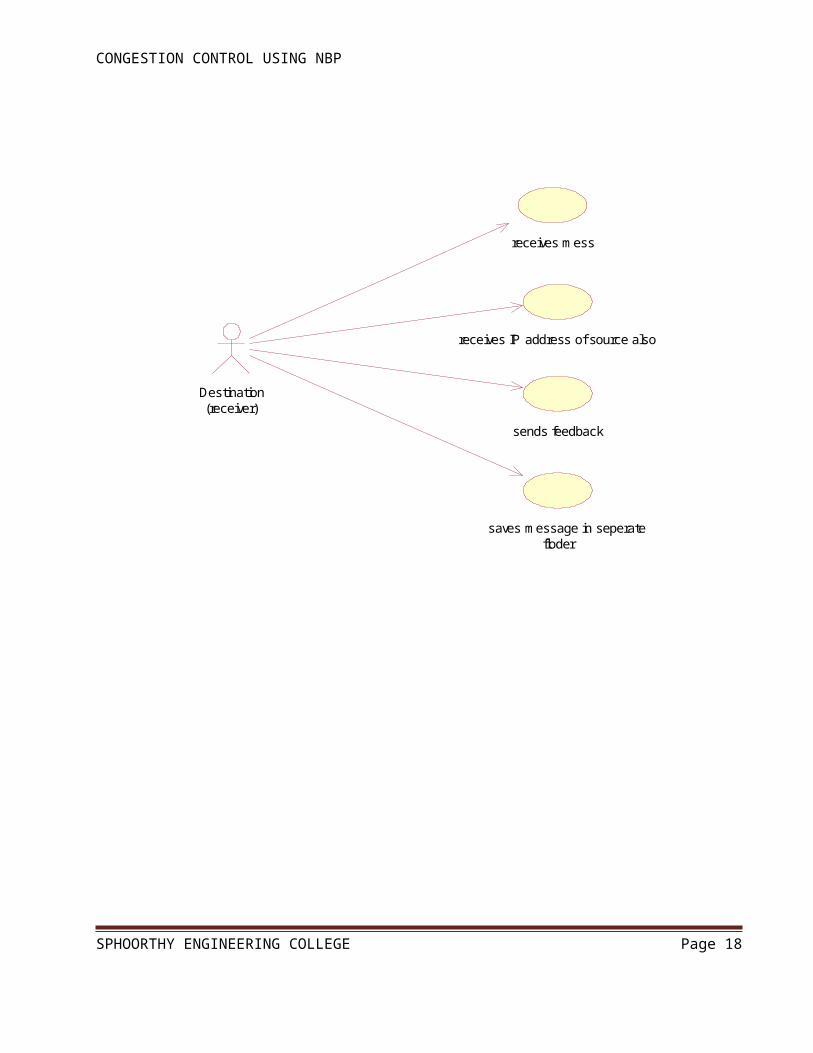
Usecase Diagram For DESTINATION
SPHOORTHY ENGINEERING COLLEGE Page 13

CONGESTION CONTROL USING NBP
receives mess
receives IP address of source also
sends feedback
Destination(receiver)
saves message in seperate floder
Class Diagram
SPHOORTHY ENGINEERING COLLEGE Page 14

CONGESTION CONTROL USING NBP
Source(users)
IP_addresPortNo.
WritesMessage()SendsMess()ReceivesACK()ReceivesReply()
1InRouter
RouterNo.Path
StoresInfo()ApplyAlgorithm()SplitsIntoPackets()ReceivesPcktFromSource()
1
1..*
message first received by Inrouter in form of packets
Destination(receivers)
IPAdressPortNo.
ReceivesMess()SavesMessage()SendsACK()SendsReply()
1..*
1..*
writes a message and sends
1OutRouter
RouterNo.Path
ReceivesPcktFromRouter()StoresInfo()ChecksIfanyCongestion()ApplyAlgorithm()
1
1..*
chedks if any congestion andsends message to receiver
Router1
PortNo.TotalNoOfPortsNoOfSystemsConnected
ForwardsMessage()
1
1
each packet split into 48bits,forwards to routre
1
1
forwards from router
1..*1..*
1
1..*
1..*
1
1 1
11
Sequence Diagram
SPHOORTHY ENGINEERING COLLEGE Page 15
CONGESTION CONTROL USING NBP
:Source
:InRouter
:Router :Destination
:OutRouter
1:activates connection
2:activates connection
3:enters IP address of destination
4:writes message and clicks on send
5: each packet is split into 48 bits
6:checks the flow by applying an algorithm
7:date,time and entire info is stored
8:forwards packet to OutRouter
9:collects the packets from Router
10:checks the flow and congestion by using RCA
11:retransmission of packets if any packets are missed
12:message will be shown as a popup on notepad
13:sends ACK
14:close connection
15:close connection
SPHOORTHY ENGINEERING COLLEGE Page 16

CONGESTION CONTROL USING NBP
Collabration Diagram
:Source
:Router
:Destination
:InRouter
:OutRoutr
11: collects the packets from Router12: checks the flow and congestion by using RCA
13: retransmission of packets if any packets are missed14: message will be shown as a popup on notepad
15: sends ACK
1: activates connection
17: close connection
5: enters IP address of destination6: writes message and clicks on send
2: activates connection
16: close connection
4: 10: forwards packet to OutRouter
3:
7: each packet is split into 48 bits8: checks the flow by applying an algorithm
9: date,time and entire info is stored
SPHOORTHY ENGINEERING COLLEGE Page 17
CONGESTION CONTROL USING NBP
6. Environment And Technology
6.1 Java
Java is a programming language originally developed by James Gosling at Sun
Microsystems(which is now a subsidiary of Oracle Corporation) and released in 1995 as a core
component of Sun Microsystems' Java platform. The language derives much of
its syntax from C and C++ but has a simpler object model and fewer low-level facilities. Java
applications are typically compiled to byte code (class file) that can run on any Java Virtual
Machine (JVM) regardless of computer architecture. Java is a general-purpose, concurrent, class-
based, object-oriented language that is specifically designed to have as few implementation
dependencies as possible. It is intended to let application developers "write once, run anywhere".
Java is currently one of the most popular programming languages in use, and is widely used from
application software to web applications.
Java is a high-level programming language that is all of the following:
Simple
Object-oriented
Distributed
Interpreted
Robust
Secure
Architecture-neutral
Portable
High-performance
Multithreaded
Dynamic
SPHOORTHY ENGINEERING COLLEGE Page 18

CONGESTION CONTROL USING NBP
What Can Java Do?
The most common types of programs are probably applets and applications, where a Java
application is a standalone program that runs directly on the Java platform.
The Java Platform:
One characteristic of Java is portability, which means that computer programs written in the
Java language must run similarly on any supported hardware/operating-system platform. This is
achieved by compiling the Java language code to an intermediate representation called Java byte
code, instead of directly to platform-specific machine code.
Java byte code instructions are analogous to machine code, but are intended to
be interpreted by a virtual machine (VM) written specifically for the host hardware. End-
users commonly use a Java Runtime Environment (JRE) installed on their own machine for
standalone Java applications, or in a Web browser for Java applets.
Standardized libraries provide a generic way to access host-specific features such as
graphics, threading and networking.
A major benefit of using bytecode is porting. However, the overhead of interpretation means
that interpreted programs almost always run more slowly than programs compiled to native
executables would. Just-in-Time compilers were introduced from an early stage that compile
bytecodes to machine code during runtime. Over the years, this JVM built-in feature has been
optimized to a point where the JVM's performance competes with natively compiled C code.[citation
needed]
The following figure depicts a Java program, such as an application or applet, that's running
on the Java platform. As the figure shows, the Java API and Virtual Machine insulates the Java
program from hardware dependencies.
SPHOORTHY ENGINEERING COLLEGE Page 19

CONGESTION CONTROL USING NBP
As a platform-independent environment, Java can be a bit slower than native code. However,
smart compilers, well-tuned interpreters, and just-in-time byte code compilers can bring Java's
performance close to that of native code without threatening portability.
Swings:
Swing is a graphical user interface library for the Java SE platform. It is possible to specify a
different look and feel through the pluggable look and feel system of Swing. Swings are set of
classes that provides more powerful & flexible components than are possible with AWT.
components explained in the Swing have more capabilities than those of AWT.
first import includes all of the public classes and interfaces from the javax.swing package.
related classes are contained in javax.swing and its sub packages, such as
javax.swing.tree.components explained in the Swing have more capabilities than those of
AWT.
It’s a light weight package, as they are not implemented by platform-specific code.
6.2 TCP/IP Socket Programming
TCP/IP Client Sockets:
TCP/IP sockets are used to implement reliable, bidirectional, persistent, point-to-point,
stream-based connections between hosts on the Internet. A socket can be used to connect Java’s I/O
system to other programs that may reside either on the local machine or on any other machine on the
Internet.
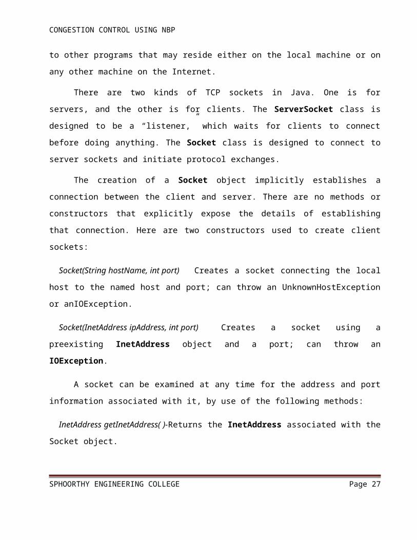
There are two kinds of TCP sockets in Java. One is for servers, and the other is for clients.
The ServerSocket class is designed to be a “listener,” which waits for clients to connect before
SPHOORTHY ENGINEERING COLLEGE Page 20

CONGESTION CONTROL USING NBP
doing anything. The Socket class is designed to connect to server sockets and initiate protocol
exchanges.
The creation of a Socket object implicitly establishes a connection between the client and
server. There are no methods or constructors that explicitly expose the details of establishing that
connection. Here are two constructors used to create client sockets:
Socket(String hostName, int port) Creates a socket connecting the local host to the named
host and port; can throw an UnknownHostException or anIOException.
Socket(InetAddress ipAddress, int port) Creates a socket using a preexisting InetAddress object
and a port; can throw an IOException.
A socket can be examined at any time for the address and port information associated with it,
by use of the following methods:
InetAddress getInetAddress( )-Returns the InetAddress associated with the Socket object.
int getPort( )-Returns the remote port to which this Socket object is connected.
int getLocalPort( )-Returns the local port to which this Socket object is connected.
Once the Socket object has been created, it can also be examined to gain access to the input
and output streams associated with it. Each of these methods can throw an IOException if the
sockets have been invalidated by a loss of connection on the Net.
InputStream getInputStream( )-Returns the InputStream associated with the invoking socket.
OutputStream getOutputStream( )-Returns the OutputStream associated with the invoking
socket.
TCP/IP Server Sockets:
Java has a different socket class that must be used for creating server applications. The
ServerSocket class is used to create servers that listen for either local or remote client programs to
connect to them on published ports. ServerSockets are quite different form normal Sockets.
SPHOORTHY ENGINEERING COLLEGE Page 21

CONGESTION CONTROL USING NBP
When we create a ServerSocket, it will register itself with the system as having an interest in
client connections. The constructors for ServerSocket reflect the port number that we wish to accept
connection on and, optionally, how long we want the queue for said port to be. The queue length
tells the system how many client connection it can leave pending before it should simply refuse
connections. The default is 50. The constructors might throw an IOException under adverse
conditions. Here are the constructors:
ServerSocket(int port)-Creates server socket on the specified port with a queue length of 50.
Serversocket(int port, int maxQueue)-Creates a server socket on the specified port with a
maximum queue length of maxQueue.
ServerSocket(int port, int maxQueue, InetAddress localAddress)-Creates a server socket on the
specified port with a maximum queue length of maxQueue. On a multihomed host, localAddress
specifies the IP address to which this socket binds.
ServerSocket has a method called accept( ), which is a blocking call that will wait for a
client to initiate communications, and then return with a normal Socket that is then used for
communication with the client.
6.3 Batch Files
Batch File is a text file containing a series of commands intended to be executed by
the command interpreter. Similar to language and other systems on mainframe and minicomputer
systems, batch files were added to ease the work required for certain regular tasks by allowing the
user to set up a batch script to automate many commands.
When a batch file is run, the shell program (usually COMMAND.COM orcmd.exe) reads the
file and executes its commands, normally line-by-line. Batch files are useful for running a sequence
of executables automatically and are often used to automate repetitive or tedious processes.
DOS batch files have the filename extension .bat. Batch files for other environments may have different extensions, e.g. .cmd or .bat.
SPHOORTHY ENGINEERING COLLEGE Page 22
CONGESTION CONTROL USING NBP
.bat: The first extension used by Microsoft for batch files. This extension runs with MS-DOS and all versions of Windows, under COMMAND.COM or cmd.exe, despite the different ways the two command interpreters execute batch files.
6.4Working Aspects Of The CFR
CFR is a network layer congestion-avoidance protocol that is aligned with the core-stateless
approach. The core-stateless approach, which has recently received a great deal of research attention
[18], [24], allows routers on the borders (or edges) of a network to perform flow classification and
maintain per-flow state but does not allow routers at the core of the network to do so. Fig. 2
illustrates this architecture. Depending on which flow it is operating on, an edge router may be
viewed as an InRouter or an OutRouter router. An edge router operating on a flow passing into a
network is called an InRouter router, whereas an edge router operating on a flow passing out of a
network is called an OutRouter router. Note that a flow may pass through more than one OutRouter
(or InRouter) router if the end-to-end path crosses multiple networks.
CFR prevents congestion collapse through a combination of per-flow rate monitoring at
OutRouter routers and per-flow rate control at InRouter routers. Rate monitoring allows an
OutRouter router to determine how rapidly each flow’s packets are leaving the network, whereas
rate control allows an InRouter router to police the rate at which each flow’s packets enter the
SPHOORTHY ENGINEERING COLLEGE Page 23

CONGESTION CONTROL USING NBP
network. Linking these two functions together are the feedback packets exchanged between InRouter
and OutRouter routers; InRouter routers send OutRouter routers forward feedback packets to inform
them about the flows that are being rate controlled, and OutRouter routers send InRouter routers
backward feedback packets to inform them about the rates at which each flow’s packets are leaving
the network. By matching the InRouter rate and OutRouter rate of each flow, CFR prevents
congestion collapse within the network.
6.4.1 Mechanism:
The architectural components, namely, the modified edge routers, which must be present in
the network
The feedback control algorithm, which determines how and when information is exchanged
between edge route
The rate control algorithm, which uses the information carried in feedback packets to
regulate flow transmission rates and thereby prevent congestion collapse in the network.
6.4.2 Architectural Components:
The only components of the network that require modification by CFR are edge routers; the
input ports of OutRouter routers must be modified to perform per-flow monitoring of bit rates, and
the output ports of InRouter routers must be modified to perform per-flow rate control. In addition,
both the InRouter and the OutRouter routers must be modified to exchange and handle CFR
feedback packets.
SPHOORTHY ENGINEERING COLLEGE Page 24

CONGESTION CONTROL USING NBP
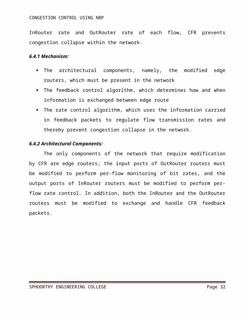
The input ports of OutRouter routers are enhanced in CFR. Fig. 3 illustrates the architecture
of an OutRouter router’s input port. Data packets sent by InRouter routers arrive at the input port of
the OutRouter router and are first classified by flow. Flow classification is performed by InRouter
routers on every arriving packet based upon a flow classification policy.
An example flow classification policy is to examine the packet’s source and destination
network addresses, and to aggregate all packets arriving on an InRouter router and destined to the
same OutRouter router into the same CFR flow (i.e., a macro-flow). Other flow classification
policies can be used, for instance, in the case of IPv6, flows may be classified by examining the
packet header’s flow label, whereas in the case of IPv4, it could be done by examining the packet’s
source and destination addresses and port numbers.
After classifying packets into flows, each flow’s bit rate is then rate monitored using a rate
estimation algorithm such as the Time Sliding Window (TSW) algorithm. These rates are collected
by a feedback controller, which returns them in backward feedback packets to an InRouter router
whenever a forward feedback packet arrives from that InRouter router.
SPHOORTHY ENGINEERING COLLEGE Page 25

CONGESTION CONTROL USING NBP
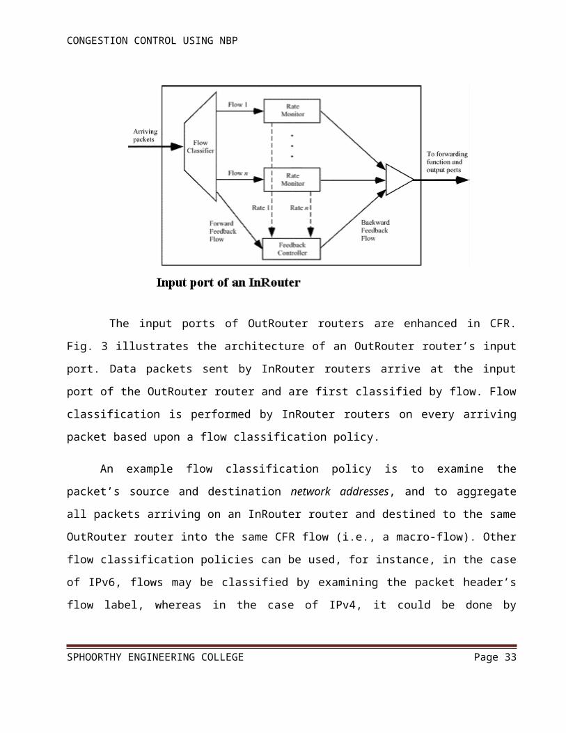
The output ports of InRouter routers are also enhanced in CFR. Each output port contains a
flow classifier, per-flow traffic shapers (e.g., leaky buckets), a feedback controller, and a rate
controller (see Fig. 4). The flow classifier classifies packets into flows, and the traffic shapers limit
the rates at which packets from individual flows enter the network. The feedback controller receives
backward feedback packets returning from OutRouter routers and passes their contents to the rate
controller. It also generates forward feedback packets that are transmitted to the network’s
OutRouter routers. To prevent congestion collapse, the rate controller adjusts traffic shaper
parameters according to a TCP-like rate-control algorithm, and the rate-control algorithm used in
CFR is described later in this section.
6.5 Leaky Bucket Algorithm
The "leaky bucket" algorithm is key to defining the meaning of conformance.
The leaky bucket analogy refers to a bucket with a hole in the bottom that causes it to "leak" at a
certain rate coresponding to a traffic cell rate parameter The "depth" of the bucket corresponds to a
SPHOORTHY ENGINEERING COLLEGE Page 26
CONGESTION CONTROL USING NBP
tolerance parameter Each cell arrival creates a "cup" of fluid flow "poured" into one or more buckets
for the use in conformance checking.
The Cell Loss Priority (CLP) bit in the ATM cell header determines which bucket(s) the cell
arrival fluid pours into. In the algorithm, a cell counter represents the bucket. This counter is
incremented by one for each incoming cell. The "leak rate" in the algorithm is the decrement rate
which reduces the counter value by one at certain intervals. This rate is given by the cell rate under
consideration and is governed by the minimum distance between two consecutive cells. The bucket
volume is analogous to the cell counter range, which is represented by the permissible time tolerance
for the incoming cells. This value is determined through the traffic contract or is set by the network
provider and is called CDVT (cell delay variation tolerance). If the counter exceeds a certain value,
the cells are assumed not to conform to the contract. To counteract this, non-conforming cells can
now either be tagged or dropped. The algorithm is called "dual leaky bucket" if several parameters
are monitored at once, or "single leaky bucket" if only one parameter is monitored.
In the "Leaky Bucket" analogy the cells do not actually flow through the bucket; only the check for
conformance to the contract does.
The process flow is well explained in the following dataflow diagram
SPHOORTHY ENGINEERING COLLEGE Page 27

CONGESTION CONTROL USING NBP
Dataflow Diagram For Leaky Buckrt Algorithm
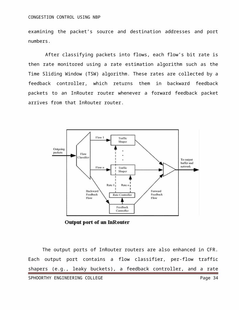
6.6 Feedback Control Algorithm
The feedback control algorithm in CFR determines how and when feedback packets are
exchanged between edge routers. Feedback packets take the form of ICMP packets and are
necessary in CFR for three reasons. First, forward feedback packets allow OutRouter routers to
discover which InRouter routers are acting as sources for each of the flows they are monitoring.
Second, backward feedback packets allow OutRouter routers to communicate per-flow bit rates to
InRouter routers. Third, forward and backward feedback packets allow InRouter routers to detect
incipient network congestion by monitoring edge-to-edge round-trip times.
SPHOORTHY ENGINEERING COLLEGE Page 28

CONGESTION CONTROL USING NBP
The contents of feedback packets are shown in Fig. 5.
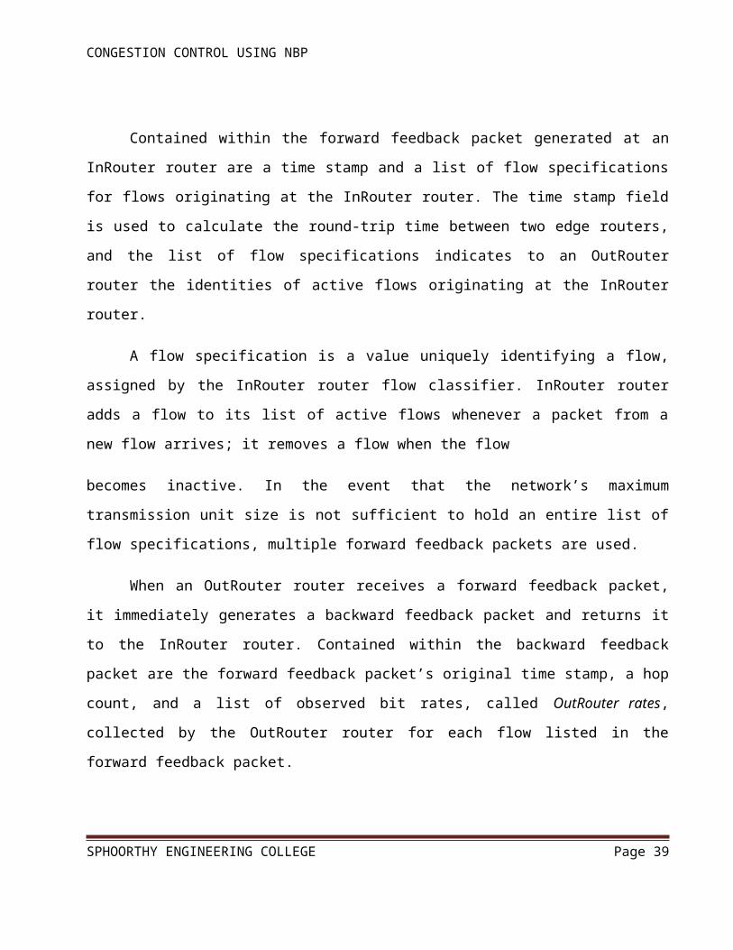
Contained within the forward feedback packet generated at an InRouter router are a time
stamp and a list of flow specifications for flows originating at the InRouter router. The time stamp
field is used to calculate the round-trip time between two edge routers, and the list of flow
specifications indicates to an OutRouter router the identities of active flows originating at the
InRouter router.
A flow specification is a value uniquely identifying a flow, assigned by the InRouter router
flow classifier. InRouter router adds a flow to its list of active flows whenever a packet from a new
flow arrives; it removes a flow when the flow
becomes inactive. In the event that the network’s maximum transmission unit size is not sufficient to
hold an entire list of flow specifications, multiple forward feedback packets are used.
When an OutRouter router receives a forward feedback packet, it immediately generates a
backward feedback packet and returns it to the InRouter router. Contained within the backward
SPHOORTHY ENGINEERING COLLEGE Page 29

CONGESTION CONTROL USING NBP
feedback packet are the forward feedback packet’s original time stamp, a hop count, and a list of
observed bit rates, called OutRouter rates, collected by the OutRouter router for each flow listed in
the forward feedback packet.
The hop count, which is used by the InRouter router’s rate-control algorithm, indicates how
many routers are in the path between the InRouter and the OutRouter router. The OutRouter router
determines the hop count by examining the time-to-live (TTL) field of arriving forward feedback
packets. When the backward feedback packet arrives at the InRouter router, its contents are passed
to the InRouter router’s rate controller, which uses them to adjust the parameters of each flow’s
traffic shaper.
In order to determine how often to generate forward feedback packets, an InRouter router
keeps a byte transmission counter for each flow it monitors. Whenever a flow’s byte transmission
counter exceeds a threshold, denoted CFR’s transmission counter threshold ( ), the InRouter router
generates and transmits a forward feedback packet to the flow’s OutRouter router, and resets the
byte transmission counters of all flows included in the feedback packet.
Using a byte transmission counter for each flow ensures that forward feedback packets are
generated more frequently when flows transmit at higher rates, thereby allowing InRouter routers to
respond more quickly to impending congestion collapse. To maintain a frequent flow of feedback
between edge routers even when data transmission rates are low, InRouter routers also generate
forward feedback packets Whenever a time-out interval is exceeded.
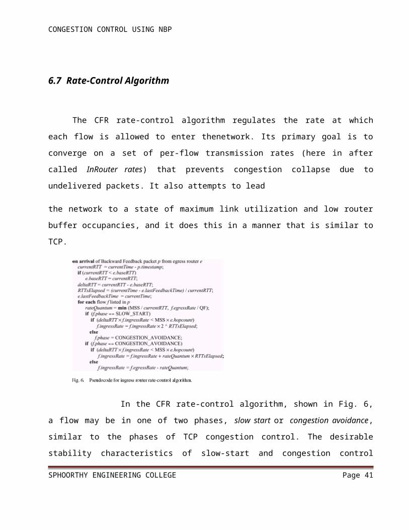
6.7 Rate-Control Algorithm
The CFR rate-control algorithm regulates the rate at which each flow is allowed to enter
thenetwork. Its primary goal is to converge on a set of per-flow transmission rates (here in after
called InRouter rates) that prevents congestion collapse due to undelivered packets. It also attempts
to lead
SPHOORTHY ENGINEERING COLLEGE Page 30

CONGESTION CONTROL USING NBP
the network to a state of maximum link utilization and low router buffer occupancies, and it does this
in a manner that is similar to TCP.
In the CFR rate-control algorithm, shown in Fig. 6, a flow may be in one of two phases, slow
start or congestion avoidance, similar to the phases of TCP congestion control. The desirable
stability characteristics of slow-start and congestion control algorithms have been proven in TCP
congestion control, and CFR expects to benefit from their well-known stability features. In CFR,
new flows entering the network start with the slow-start phase and proceed to the congestion-
avoidance phase only after the flow has experienced incipient congestion.
The rate-control algorithm is invoked whenever a backward feedback packet arrives at an
InRouter router. Recall that backward feedback packets contain a timestamp and a list of flows
arriving at the OutRouter router from the InRouter router as well as the monitored OutRouter rates
for each flow. Upon the arrival of a backward feedback packet, the algorithm calculates the current
round-trip time (currentRTT in Fig. 6) between the edge routers and updates the base round-trip time
(e.base RTT), if necessary.
The base round-trip time (e.base RTT) reflects the best-observed round-trip time between the
two edge routers. The algorithm then calculates deltaRTT, which is the difference between the
current round-trip time (currentRTT) and the base round-trip time (e.baseRTT). A deltaRTT value
greater than zero indicates that packets are requiring a longer time to traverse the network than they
once did, and this can only be due to the buffering of packets within the network.
SPHOORTHY ENGINEERING COLLEGE Page 31
CONGESTION CONTROL USING NBP
CFR’s rate-control algorithm decides that a flow is experiencing incipient congestion
whenever it estimates that the network has buffered the equivalent of more than one of the flow’s
packets at each router hop. To do this, the algorithm first computes the product of the flow’s
InRouter rate (f.InRouterRate) and deltaRTT (i.e., f.InRouterRate deltaRTT). This value provides an
estimate of the amount of the flow’s data that is buffered somewhere in the network. If this amount
(i.e., f.InRouterRate deltaRTT) is greater than the number of router hops between the InRouter and
the OutRouter routers (e.hopcount) multiplied by the size of the largest possible packet (MSS) (i.e.,
MSS e.hopcount), then the flow is considered to be experiencing incipient congestion.
The rationale for determining incipient congestion in this manner is to maintain both high
link utilization and low queuing delay. Ensuring there is always at least one packet buffered for
transmission on a network link is the simplest way to achieve full utilization of the link, and deciding
that congestion exists when more than one packet is buffered at the link keeps queuing delays low.
Therefore, CFR’s rate-control algorithm allows the “equivalent” of e.hopcount packets to be
buffered in flow’s path before it reacts to congestion by monitoring deltaRTT.1 a similar approach is
SPHOORTHY ENGINEERING COLLEGE Page 32
Propagation delay
Queuing delay
Round-trip time
Source destination
CONGESTION CONTROL USING NBP
used in the DEC bit congestion-avoidance mechanism. Furthermore, the approach used by CFR’s
rate control algorithm to detect congestion, by estimating whether the network has buffered the
equivalent of more than one of the flow’s packets at each router hop, has the advantage that, when
congestion occurs, flows with higher InRouter rates detect congestion first. This is because the
condition f.InRouterRate deltaRTT MSS e.hopcount fails first for flows with a large InRouter rate,
detecting that the path is congested due to InRouter flow.
When the rate-control algorithm determines that a flow is not experiencing congestion, it
increases the flow’s InRouter rate. If the flow is in the slow-start phase, its InRouter rate is doubled
for each round-trip time that has elapsed since the last backward feedback packet arrived
(f.InRouter).
The estimated number of round-trip times since the last feedback packet arrived is denoted as
RTTs Elapsed. Doubling the InRouter rate during slow start allows a new flow to rapidly capture
available bandwidth when the network is underutilized. If, on the other hand, the flow is in the
congestion-avoidance phase, then its InRouter rate is conservatively incremented by one rate
Quantum value for each round trip that has elapsed since the last backward feedback packet arrived
(f.InRouterrate rate Quantum RTTsElapsed). This is done to avoid the creation of congestion. The
rate quantum is computed as the maximum segment size divided by the current round-trip time
between the edge routers.
This results in rate growth behavior that is similar to TCP in its congestion-avoidance phase.
Furthermore, the rate quantum is not allowed to exceed the flow’s current OutRouter rate divided by
a constant quantum factor (QF). This guarantees that rate increments are not excessively large when
the round-trip time is small. When the rate-control algorithm determines that a flow is experiencing
incipient congestion, it reduces the flow’s InRouter rate.
If a flow is in the slow-start phase, it enters the congestion-avoidance phase. If a flow is
already in the congestion-avoidance phase, its InRouter rate is reduced to the flow’s OutRouter rate
decremented by a constant value. In other words, an observation of incipient congestion forces the
InRouter router to send the flow’s packets into the network at a rate slightly lower than the rate at
which they are leaving the network.
SPHOORTHY ENGINEERING COLLEGE Page 33
CONGESTION CONTROL USING NBP
CFR’s rate-control algorithm is designed to have minimum impact on TCP flows. The rate at
which CFR regulates each flow (f.InRouterRate) is primarily a function of the round-trip time
between the flow’s InRouter and OutRouter routers (currentRTT). In CFR, the initial InRouter rate
for a new flow is set to be MSS/e.baseRTT, following TCP’s initial rate of one segment per round-
trip time.
CFR’s currentRTT is always smaller than TCP’s end-to-end round-trip time (as the distance
between InRouter and OutRouter routers, i.e., the currentRTT in CFR, is shorter than the end-to-end
distance, i.e., TCP’s round-trip time). As a result, f.InRouterRate is normally larger than TCP’s
transmission rate when the network is not congested, since the TCP transmission window increases
at a rate slower than CFR’s f.InRouterRate increases. Therefore, CFR normally does not regulate
TCP flows.
However, when congestion occurs, CFR reacts first by reducing f.InRouterRate and,
therefore, reducing the rate at which TCP packets are allowed to enter the network. TCP eventually
detects the congestion (either by losing packets or due to longer round-trip times) and then promptly
reduces its transmission rate. From this time point on, f.InRouterRate becomes greater than TCP’s
transmission rate, and therefore, CFR’s congestion control does not regulate TCP sources until
congestion happens again.
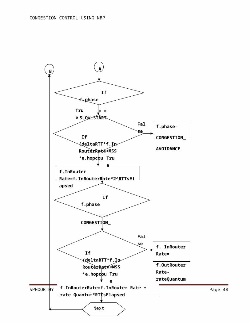
The process flow is well explained in the following dataflow diagram,
SPHOORTHY ENGINEERING COLLEGE Page 34

CONGESTION CONTROL USING NBP
Dataflow Diagram For Rate Control Algorithm
SPHOORTHY ENGINEERING COLLEGE Page 35
If
CurrentRTT<e.baseRTT
On arrival of backward feedback packet p from OutRouter router e
Current RTT =Current Time -p.times tamp
Delta RTT=-Current RTT-
e.base RTT
e.base RTT=Current RTT
RTTs Elapsed= (Current Time-e.last FeedbackTime)/CurrentRTT
e.last FeedbackTime=Current Time
For each flow f listed in p
Rate Quantum=min (MSS/currentRTT, f.egreesRate/QF)
AB
True
False

CONGESTION CONTROL USING NBP
SPHOORTHY ENGINEERING COLLEGE Page 36
f.phase=
CONGESTION_
AVOIDANCE
If (deltaRTT*f.InRouterRate<MSS*e.hopcount)
f.InRouter Rate=f.InRouterRate*2^RTTsElapsed
If f.phase
= = CONGESTION_
AVOIDANCE
If (deltaRTT*f.InRouterRate<MSS*e.hopcount)
f.InRouterRate=f.InRouter Rate + rate Quantum*RTTsElapsed
f. InRouter Rate=
f.OutRouterRate-rateQuantum
Next
NEXT
True
True
False
True
False
If f.phase
= = SLOW_START
B A

CONGESTION CONTROL USING NBP
6.8 Time Sliding Window Algorithms
Sliding Window Protocols are a feature of packet-based data transmission protocols. They
are used where reliable in-order delivery of packets is required, such as in the data link layer (OSI
model) as well as in TCP (transport layer of the OSI model).
Conceptually, each portion of the transmission (packets in most data link layers, but bytes in
TCP) is assigned a unique consecutive sequence number, and the receiver uses the numbers to place
received packets in the correct order, discarding duplicate packets and identifying missing ones. The
problem with this is that there is no limit of the size of the sequence numbers that can be required.
By placing limits on the number of packets that can be transmitted or received at any given
time, a sliding window protocol allows an unlimited number of packets to be communicated using
fixed-size sequence numbers.
For the highest possible throughput, it is important that the transmitter is not forced to stop
sending by the sliding window protocol earlier than one round-trip delay time (RTT). The limit on
the amount of data that it can send before stopping to wait for an acknowledgment should be larger
than the bandwidth-delay product of the communications link. If it is not, the protocol will limit the
effective bandwidth of the link.
SPHOORTHY ENGINEERING COLLEGE Page 37
CONGESTION CONTROL USING NBP
So far, the protocol has been described as if sequence numbers are of unlimited size, ever-
increasing. However, rather than transmitting the full sequence number x in messages, it is possible
to transmit only x mod N, for some finite N. (N is usually a power of 2.)
Since it guarantees that nt−na ≤ wt, there are at most wt+1 possible sequence numbers that
could arrive at any given time. Thus, the transmitter can unambiguously decode the sequence
number as long as N > wt.
A stronger constraint is imposed by the receiver. The operation of the protocol depends on
the receiver being able to reliably distinguish new packets (which should be accepted and processed)
from retransmissions of old packets (which should be discarded, and the last acknowledgment
retransmitted). This can be done given knowledge of the transmitter's window size. After receiving a
packet numb The receiver also knows that the transmitter's nacannot be higher than the highest
acknowledgment ever sent, which is nr. So the highest sequence number we could possibly see
isnr+wt ≤ ns+wt.
SPHOORTHY ENGINEERING COLLEGE Page 38
CONGESTION CONTROL USING NBP
Thus, there are 2wt different sequence numbers that the receiver can receive at any one time.
It might therefore seem that we must haveN ≥ 2wt. However, the actual limit is lower.
The additional insight is that the receiver does not need to distinguish between sequence
numbers that are too low (less than nr) or that are too high (greater than or equal to ns+wr). In either
case, the receiver ignores the packet except to retransmit an acknowledgment.
Thus, it is only necessary that N ≥ wt+wr.
The process flow is well explained in the following dataflow diagram,
SPHOORTHY ENGINEERING COLLEGE Page 39

CONGESTION CONTROL USING NBP
Dataflow Diagram For Time Sliding Window Protocols
SPHOORTHY ENGINEERING COLLEGE Page 40
Arrival of the Forward Feedback at the OutRouter Router
Start the timer
If Packets are arrived
Wait until the packet is forward
Current Packet is send
Wait until the Packet is arrived
Yes
No
Acknowledgement is backward to InRouter
If Packets are forwarded
Yes
No
If no Packet to Forwarded
Stop the timerYes
Forward the next packet
No
CONGESTION CONTROL USING NBP
7. Implementation
7.1 Related work:
The maladies of congestion collapse from undelivered packets and of unfair bandwidth
allocations have not gone unrecognized. Some have argued that there are social incentives for
multimedia applications to be friendly to the network, since an application would not want to be held
responsible for throughput degradation in the Internet. Nevertheless, unresponsive UDP flows are
becoming disturbingly frequent in the Internet, and they are an example that the Internet cannot rely
solely on social incentives to control congestion or to operate fairly.
Some have argued that congestion collapse and unfairness can be mitigated through the use
of improved packet scheduling or queue management mechanisms in network routers. For instance,
per-flow packet scheduling mechanisms such as WFQ attempt to offer fair allocations of bandwidth
to flows contending for the same link.
For illustration, consider the example shown in Fig. 1. In this example, two unresponsive
flows (flow A and flow B) compete for bandwidth in a network containing two bottleneck links (-
and -) arbitrated by a fair queuing mechanism at routers and, at the first bottleneck link
(-),fairqueuing at router ensures that each flow receives half of the link’s available bandwidth (750
kb/s).On the second bottleneck link (-), much of the traffic from flow B is discarded due to the link’s
limited capacity (128 kb/s). Hence, flow-A achieves a throughput of 750 kb/s, and flow B achieves a
throughput of 128 kb/sc.
SPHOORTHY ENGINEERING COLLEGE Page 41

CONGESTION CONTROL USING NBP
Clearly, congestion collapse has occurred, because flow B’s packets, which are ultimately
discarded on the second bottleneck link (-), limit the throughput of flow A across the first bottleneck
link (-). An allocation of bandwidth is said to be globally max-min fair if, at every link, all active
flows not bottlenecked at another link are allocated a maximum, equal share of the link’s remaining
bandwidth [22]. A globally max-min fair allocation of bandwidth for the example shown in Fig. 1
would have been 1.372 Mb/s for flow A and 128 kb/s for flow B.
7.2 Pseudo Code
import java.net.*;
import java.io.*;
class CFRDestination
{
public static void main(String args[]) throws IOException
{
System.out.println("******************************DESTINATION***************************************");
String instring=" ";
String s=" ";
int length=0;
String dest=" ";
try
{
ServerSocket sock1 = new ServerSocket(7711);
SPHOORTHY ENGINEERING COLLEGE Page 42

CONGESTION CONTROL USING NBP
while(true)
{
System.out.println("waiting..........");
Socket insocket1 = sock1.accept();
System.out.println("connected sucessfully.............");
try
{
ObjectInputStream ois=new ObjectInputStream(insocket1.getInputStream());
instring=(String) ois.readObject();
}
catch(ClassNotFoundException e)
{
e.printStackTrace();
}
length=instring.length();
int st=instring.indexOf('`');
int end=instring.lastIndexOf('`');
dest=instring.substring(st+1,end);
if((instring.substring((instring.length()-4),instring.length())).equals("null"))
{
s=instring.substring(end+1,length-4);
}
else
SPHOORTHY ENGINEERING COLLEGE Page 43

CONGESTION CONTROL USING NBP
{
s=instring.substring(end+1,length);
}
byte data[]=s.getBytes();
FileOutputStream fos=new FileOutputStream(dest+".txt",true);
fos.write(data);
Runtime r = Runtime.getRuntime();
Process p = null;
p = r.exec("notepad"+" "+dest+".txt");
}
}
catch(UnknownHostException e)
{
e.printStackTrace();
}
}
}
SPHOORTHY ENGINEERING COLLEGE Page 44

CONGESTION CONTROL USING NBP
8. Testing
8.1 Unit Testing
Software testing is critical element of software quality assurance and represents ultimate
review of specification, design and coding. Test case design focuses on a set of technique for the
creation of test cases that meet overall testing objectives. Planning and testing of a programming
system involve formulating a set of test cases, which are similar to the real data that the system is
intended to manipulate. Test castes consist of input specifications, a description of the system
functions exercised by the input and a statement of the extended output. Through testing involves
producing cases to ensure that the program responds, as expected, to both valid and invalid inputs,
that the program perform to specification and that it does not corrupt other programs or data in the
system.
In principle, testing of a program must be extensive. Every statement in the program
should be exercised and every possible path combination through the program should be executed
at least once. Thus, it is necessary to select a subset of the possible test cases and conjecture that
this subset will adequately test the program.
8.2 Integration Testing
It involves the testing of the order in which the different modules are combined to produce
the functioning whole. Integration testing generally throws light on the order of arrangement of
units, modules, systems, subsystems and the entire product.
The proposed system, “ the client server architecture “ inherits a bottom-up integration
strategy in which all the subsystem and the modules involved in it are independently tested and
integrated to from the entire system, which is then tested as a whole.
SPHOORTHY ENGINEERING COLLEGE Page 45

CONGESTION CONTROL USING NBP
For the testing of this system it was required that the software be tested for performing its
basic functions that are as follows: -
Start the server first and then client, then there is no error.Start the server and client, and
then stop the server and a send a message from client. The error is no server connection.Start client
first, then the error is client is not connected to the server.
8.3 Validation Testing
Validation testing is used to validate the correct user name and password and card number
and pin number and if person gives the invalid username and password, at that time the card
validation does not execute.
8.4 Performance Testing
Performance testing determines the amount of execution thime spent in various parts of the
unit, program throughput, response time and device utilization by the program unit.
SPHOORTHY ENGINEERING COLLEGE Page 46

CONGESTION CONTROL USING NBP
9. Screen Shots
Execution of batch files(.bat file)
SPHOORTHY ENGINEERING COLLEGE Page 47
CONGESTION CONTROL USING NBP
Sender writing and sending a text message
SPHOORTHY ENGINEERING COLLEGE Page 48

CONGESTION CONTROL USING NBP
InRouter
SPHOORTHY ENGINEERING COLLEGE Page 49

CONGESTION CONTROL USING NBP
The Router connection is being monitored
SPHOORTHY ENGINEERING COLLEGE Page 50

CONGESTION CONTROL USING NBP
Main Router
SPHOORTHY ENGINEERING COLLEGE Page 51

CONGESTION CONTROL USING NBP
OutRouter
SPHOORTHY ENGINEERING COLLEGE Page 52

CONGESTION CONTROL USING NBP
Destination
SPHOORTHY ENGINEERING COLLEGE Page 53

CONGESTION CONTROL USING NBP
10. Conclusion
In this project, we have presented a novel congestion-avoidance mechanism for the Internet
called CFR mechanism. Unlike existing Internet congestion control approaches, which rely solely on
end-to-end control, CFR is able to prevent congestion collapse from undelivered packets. CFR by
provides fair bandwidth allocations in a core-stateless fashion.
CFR ensures at the border of the network that each flow’s packets do not enter the network
faster than they are able to leave it, at the core of the network that flows transmitting at a rate lower
than their fair share experience no congestion, i.e., low network queuing delay. This allows the
transmission rate of all flows to converge to the network fair share. CFR requires no modifications to
core routers nor to end systems.
Only edge routers are enhanced so that they can perform the requisite per-flow monitoring,
per-flow rate-control and feedback exchange operations.Simulation results show that CFR
successfully prevents congestion collapse from undelivered packets. They also show that, while CFR
is unable to eliminate unfairness on its own, it is able to achieve approximate global max-min
fairness for competing network flows when combined with ECSFQ, they approximate global max-
min fairness in a completely core-stateless fashion.
SPHOORTHY ENGINEERING COLLEGE Page 54

CONGESTION CONTROL USING NBP
11. References
[1] S. Floyd and K. Fall, “Promoting the use of end-to-end congestion control in the internet,”
IEEE/ACM Trans. Networking, vol. 7, pp. 458–472,
Aug. 1999.
[2] J. Nagle, “Congestion control in IP/TCP Internet works,” Internet Engineering
Task Force, RFC 896, Jan. 1984.
[3] V. Jacobson, “Congestion avoidance and control,” ACM Comput. Commun. Rev., vol. 18, no. 4,
pp. 314–329, Aug. 1988.
[4] (1999, Jan.) Real Broadcast Network White Paper. Real Networks, Inc. [Online]. Available:
http://www.real.com/solutions/rbn/ whitepaper.html
[5] (1999, Jan.) Real Video Technical White Paper. Real Networks Inc. [Online]. Available:
http://www.real.com/devzone/library/whitepapers/ overview.html
[6] A. Habib and B. Bhargava, “Unresponsive flow detection and control in differentiated services
networks,” presented at the 13th IASTED Int. Conf. Parallel and Distributed Computing and
Systems, Aug. 2001.
[10] A. Mustafa and M. Hassan, “End to end IP rate control,” in Recent Advances in Computing and
Communications. New York: McGraw-Hill, Dec. 2000, pp. 279–282.
[11] A. Rangarajan and A. Acharya, “ERUF: Early regulation of unresponsive best-effort traffic,”
presented at the Int. Conf. Networks and Protocols, Oct. 1999.
[12] S. Robinson, “Multimedia transmission drive net toward gridlock,” New York Times, Aug. 23,
1999.
SPHOORTHY ENGINEERING COLLEGE Page 55

CONGESTION CONTROL USING NBP
SPHOORTHY ENGINEERING COLLEGE Page 56