04 orca tutorial: preliminary: creating an air handling ... create an air handling unit database...
TRANSCRIPT

ORCA Tutorial: Create an Air Handling Unit Database

Create an Air Handling Unit Database
ORCA System Tutorial Edition. 2.10 Page 2 Preliminary Total Pages in this Section: 11
2
First Released as separate PDF files March 7, 2002 (Ed. 2.0) Released as separate PDF files August 8, 2002 (Ed. 2.01) Released as PDF file April 30, 2005 (Ed. 2.10) Copyright © Delta Controls Inc. All rights reserved Document Title: ORCA Tutorial Document Number None - PDF file Current Edition Edition 2.10 Date of current revision April 30 , 2005
No part of this manual may be reproduced, transmitted, transcribed, stored in a retrieval system, or translated into any language (natural or computer), in any form or by any means, without the prior written permission of Delta Controls Inc. Limited permission is granted to reproduce documents released in Adobe™ Portable Document Format (PDF) electronic format in paper format. Documents released in PDF electronic format may be printed by end-users for their own use using a printer such as an inkjet or laser device. Authorized distributors of Delta Controls Inc. products (Delta Partners) may print PDF documents for their own internal use or for use by their customers. Authorized Delta Partners may engage a printing or copying company to produce copies of released PDF documents with the prior written permission of Delta Controls Inc. Information in this document is subject to change without notice and does not represent a commitment to past versions of this document on the part of Delta Controls Inc. Delta Controls Inc. may make improvements and/or changes to this manual/the associated software/or associated hardware at any time. BACspec, BACstat, the Delta logo, IntelliNet, ORCA, the ORCA logo, ORCAview, the ORCAview logo, ORCAweb and Virtual Stat are trademarks of Delta Controls Inc. IntelliNet®, BACstat®, ORCA®, ORCAview® and Virtual Stat® are registered trademark of Delta Controls Inc. Windows 98® Windows NT® Windows 2000® Windows ME® and Windows XP® are registered trademarks of Microsoft Corporation. USRobotics® is a trademark of 3Com Corporation. Intel® is a registered trademark of Intel Corporation. Echelon® LonWorks® are U.S. registered trademarks of Echelon Corporation. All other trademarks are the property of their respective owners.

Table of contents (Concise) Document Control
ORCA System Tutorial
Total Pages in this Section: 11 Preliminary Edition. 2.10 Page 3
3
Document Control Title: ORCA Tutorial Product Number: None - PDF file for release on CD-ROM Edition Date Changes 1.0 June 22,
2000 Included as Chapter 4 of the ORCAview 3.20 Technical Reference manual. Released as a PDF file only.
2.0 March 7, 2002
Make ORCA Tutorial available as a separate PDF document that is not part of the Technical Reference manual. Distributed on a CD-ROM that includes database files.
2.01 August 8, 2002
Did minor technical revisions and updated four screen captures. Fixed format and copy editing issues.
2.1 Apr. 30, 2005
Revise tutorial and make more modular by organizing as lessons. It is included as Chapter 4 of the ORCAview 3.30 Release 2 Technical Reference manual Edition 1.40 but is available for separate PDF distribution with the database files.

Create an Air Handling Unit Database
ORCA System Tutorial Edition. 2.10 Page 4 Preliminary Total Pages in this Section: 11
4
TABLE OF CONTENTS (CONCISE) TABLE OF CONTENTS (CONCISE)................................................................ 4
TABLE OF CONTENTS (DETAILED)............................................................. 5
TUTORIAL OVERVIEW (GETTING STARTED).......................................... 9
LESSON 1 – L1 REVIEWING THE CONTROL SYSTEM DEFINITION PROCESS..................................................................................................... 12
LESSON 2 – L2 REVIEWING THE HARDWARE DEFINITION AND SETUP PROCESS....................................................................................... 23
LESSON 3 – L3 PREPARING THE HARDWARE AND SOFTWARE....... 26
LESSON 4 – L4 WORKING WITH OBJECTS IN NAVIGATOR............... 32
LESSON 5 – L5 CREATING INPUT AND OUTPUT OBJECTS................. 39
LESSON 6 – L6 CREATING SETPOINTS, VARIABLES AND CONTROL LOOPS ......................................................................................................... 49
LESSON 7 – L7 CREATING SCHEDULES, CALENDARS AND OPTIMUM STARTS .................................................................................. 58
LESSON 8 – L8 CREATING TOTALIZERS.................................................. 66
LESSON 9 – L9 CREATING GCL+ PROGRAMS ........................................ 69
LESSON 10 – L10 CREATING TREND LOGS AND MULTI-TRENDS .... 84
LESSON 11 – L11 CREATING ALARMS (EVENTS)................................... 91
GRAPHICS OPTION....................................................................................... 103
APPENDIX A – SYSTEM STARTUP............................................................ 105
APPENDIX B – INSTALL SENTINEL DRIVERS....................................... 111
APPENDIX C – INSTALL ORCAVIEW OWS ............................................ 114

Table of Contents (Detailed) Document Control
ORCA System Tutorial
Total Pages in this Section: 11 Preliminary Edition. 2.10 Page 5
5
TABLE OF CONTENTS (DETAILED) DOCUMENT CONTROL..............................................................................................3 TABLE OF CONTENTS (CONCISE) ................................................................4
TABLE OF CONTENTS (DETAILED)..............................................................5
TUTORIAL OVERVIEW (GETTING STARTED) ..........................................9 Action: Print a paper copy of the tutorial ....................................9
OVERALL LEARNING OBJECTIVES............................................................................9 REQUIREMENTS........................................................................................................9 COPYING TUTORIAL FILES .....................................................................................10
Action: Copy the Tutorial Files.................................................10 To copy the Tutorial files: .........................................................10
SYSTEM GRAPHIC ..................................................................................................10 LESSON 1 – L1 REVIEWING THE CONTROL SYSTEM DEFINITION
PROCESS .....................................................................................................12 INTRODUCTION ......................................................................................................12 CREATING POINTS LIST..........................................................................................12
Define Sequence of Operations...............................................................13 Define I/O List.........................................................................................15 Define I/O Objects ..................................................................................16 Define Other Software Objects ...............................................................16 Naming Conventions for Objects ............................................................18
To name an object: ....................................................................19 Define Complete List of Named Required Objects..................................19 Moving On ..............................................................................................22
LESSON 2 – L2 REVIEWING THE HARDWARE DEFINITION AND SETUP PROCESS .......................................................................................23
SELECTING CONTROLLER HARDWARE FOR THE TUTORIAL SYSTEM (DSC-1212E)23 Description of a DSC Controller ............................................................24 Board Layout (DSC-1212E)....................................................................25 Moving On ..............................................................................................25
LESSON 3 – L3 PREPARING THE HARDWARE AND SOFTWARE .......26 PREPARING YOUR HARDWARE...............................................................................26
Action: A: Address the controller..............................................27 A: To address the controller: .....................................................27 Action: B: Clear the database....................................................28 B: To clear a database from the battery-backed memory
of a Delta controller:............................................................28 CONNECTING CONTROLLER HARDWARE ...............................................................28
Connect the Controller to OWS Using Ethernet .....................................29 Action: C: Connect the controller to OWS................................29 C: To connect the Ethernet cable to a DSC-1212
controller: ............................................................................29 Connect the Power to the Controller ......................................................29
Action: D: Connect the power to the DSC-1212E controller..............................................................................29
D: To connect the power to a DSC-1212 controller: .................29 Attach the Software Key..........................................................................29

Create an Air Handling Unit Database
ORCA System Tutorial Edition. 2.10 Page 6 Preliminary Total Pages in this Section: 11
6
Action: E: Attach the software key........................................... 29 E: To attach the Delta Controls software key: .......................... 30
INSTALLING THE SOFTWARE.................................................................................. 30 Install the Sentinel Drivers..................................................................... 30
Action: F: Install the Sentinel drivers ....................................... 30 Installing Operator Workstation (OWS)................................................. 31
Action: G: Install the ORCAview OWS software .................... 31 Log Into ORCAview................................................................................ 31
Action: H: Start ORCAview OWS ........................................... 31 H: To start ORCAview: ............................................................ 31
Moving On.............................................................................................. 31 LESSON 4 – L4 WORKING WITH OBJECTS IN NAVIGATOR............... 32 DESCRIPTION OF NAVIGATOR................................................................................ 32 COMPONENTS OF THE NAVIGATOR WINDOW......................................................... 34
Components: Left Pane-Network Tree ................................................... 34 Components: Right Pane-Controller Objects......................................... 36 Use Network Tree (Left Pane) - Mouse Commands ............................... 36 Load a Database .................................................................................... 36
To load a database: ................................................................... 36 Save a Database ..................................................................................... 36
To save a database for a single controller:................................ 37 Load Default Database........................................................................... 37
Action: Load the default database............................................. 37 To load the default database: .................................................... 37
Set the Controller Time and Date........................................................... 38 Action: Set Panel Time............................................................. 38
Name the Controller ............................................................................... 38 Action: Name your controller ................................................... 38 To name a controller:................................................................ 38
Moving On.............................................................................................. 38 LESSON 5 – L5 CREATING INPUT AND OUTPUT OBJECTS................. 39 INTRODUCTION...................................................................................................... 39
Name Objects Using a Naming Convention ........................................... 40 To name an object:.................................................................... 40
Create Object References (System Numbers) ......................................... 40 Link One Object to Another.................................................................... 41
CREATING THE INPUTS .......................................................................................... 41 Action: Create the Supply Fan Status Binary Input object ....... 41 To create an Input object: ......................................................... 41 Action: Create the 10 remaining Input objects ......................... 42 To create an Object (concise version)....................................... 43
CREATING THE OUTPUTS....................................................................................... 44 Action: Create the Supply Fan Status Binary Output
object................................................................................... 44 To create an Output object:....................................................... 44 Action: Create the 6 remaining Output objects......................... 47 To create an Object (concise version)....................................... 47
Moving On.............................................................................................. 48 LESSON 6 – L6 CREATING SETPOINTS, VARIABLES AND CONTROL
LOOPS ......................................................................................................... 49 Create Analog and Binary Variables ..................................................... 49
Table of Contents (Detailed) Document Control
ORCA System Tutorial
Total Pages in this Section: 11 Preliminary Edition. 2.10 Page 7
7
Action: Create the Supply Air Temperature Setpoint Analog Variable object ........................................................49
To create an Analog Variable object: ........................................50 Action: Create the 5 Remaining Analog Variable objects.........51
Create Multi-State Variables ..................................................................51 Action: Create the AHU1 Occupancy Multi-State
Variable object.....................................................................51 To create an Multi-State Variable object:..................................51
Moving On ..............................................................................................52 CREATING PID CONTROL LOOPS ...........................................................................53
Creating Control Loops (CO) .................................................................53 Action: Create the four Control Loop objects (CO1 –
CO4) ....................................................................................53 Action: Configure the Setup and Tuning tabs for the four
Control Loop objects ...........................................................54 Moving On ..............................................................................................57
LESSON 7 – L7 CREATING SCHEDULES, CALENDARS AND OPTIMUM STARTS...................................................................................58
Create Schedules.....................................................................................58 Action: Create the Schedule object (SCH1) ..............................58 To create a Schedule object:......................................................59
Create Calendars ....................................................................................60 Action: Create the Calendar object (CAL1) ..............................60 To create a Calendar object: ......................................................60
Create Optimum Start .............................................................................62 Action: Create the two Optimum Start objects (OS1-
OS2).....................................................................................62 To create an Optimum Start object:...........................................63
Moving On ..............................................................................................65 LESSON 8 – L8 CREATING TOTALIZERS ..................................................66
Action: Create the two Binary Totalizers objects (BT1-BT2).....................................................................................66
To create a Binary Totalizer ......................................................67 Moving On ..............................................................................................68
LESSON 9 – L9 CREATING GCL+ PROGRAMS .........................................69 INTRODUCTION ......................................................................................................69 WRITING GCL+ PROGRAMS TO CONTROL THE SYSTEM ........................................69
The Basics ...............................................................................................70 Guidelines for Creating Programs..........................................................71 Program for Fan Control........................................................................72
Action: Create Fan Control Program (PG2):.............................73 Program Testing .....................................................................................73
Action: Create Master Program (PG1) ......................................73 To test a Program: .....................................................................74
PROGRAMS FOR TUTORIAL (PG3-PG8)..................................................................76 Action: Create Programs (PG3-PG8): .......................................76
PG3 Occupancy Program.......................................................................77 PG4 Humidification Program.................................................................78 PG5 Mixed Air Control Program ...........................................................79 PG6 Heating Control Program...............................................................80 PG8 Setpoint Control Program ..............................................................82 Moving On ..............................................................................................83
Create an Air Handling Unit Database
ORCA System Tutorial Edition. 2.10 Page 8 Preliminary Total Pages in this Section: 11
8
LESSON 10 – L10 CREATING TREND LOGS AND MULTI-TRENDS .... 84 CREATING TREND LOGS ........................................................................................ 84
Action: Create Trend Log objects as required .......................... 84 To create a Trend Log............................................................... 84
Configure a Trend Log ........................................................................... 85 Action: Configure Trend Log objects as required..................... 85
CREATING MULTI-TRENDS.................................................................................... 86 Action: Create the Multi-Trend objects as required.................. 86 To create a Multi-Trend:........................................................... 87
Configure a Multi-Trend ........................................................................ 87 Action: Configure Multi-Trends objects as required ................ 87 To add a Trend Log to a Multi-Trend using drop and
drag: .................................................................................... 88 MULTI-TREND OBJECT COMPONENTS ................................................................... 89
View a Multi-Trend................................................................................. 89 To view all the Multi-Trend data on a graph: ........................... 89 To zoom in or zoom out on a Multi-Trend graph: .................... 89 To view all data in a Multi-Trend graph by scrolling
forward and backward:........................................................ 89 Tune and Troubleshoot a System............................................................ 90 Moving On.............................................................................................. 90
LESSON 11 – L11 CREATING ALARMS (EVENTS)................................... 91 INTRODUCTION: COMMON BACNET EVENT TYPES............................................... 91 CREATING AN EVENT ............................................................................................ 93
Action: Create Event objects (EV1-EV10)............................... 93 To create and configure a Command Failure Event: ................ 94 Action: Configure Event objects (EV1-EV10) Setup tab ......... 96
Configure Messages Tab ...................................................................... 101 Action: Configure Event objects (EV1-EV10) Messages
tab...................................................................................... 101 Configure Event Class Tab................................................................... 101
Action: Configure Event objects (EV1-EV10) Event Class tab ............................................................................ 102
Moving On............................................................................................ 102 GRAPHICS OPTION....................................................................................... 103
Action: Copy and then open the Demokit_AHU.gpc file ....... 103 To open a Site Graphic drawing: ............................................ 104
APPENDIX A – SYSTEM STARTUP............................................................ 105 TUNING A CONTROL LOOP .................................................................................. 105
Tune a Loop Using a Multi-Trend........................................................ 105 Tune a Controller ................................................................................. 107
APPENDIX B – INSTALL SENTINEL DRIVERS....................................... 111 Install Sentinel Drivers......................................................................... 111
To install the Sentinel driver from the ORCAview CD-ROM: ................................................................................ 111
APPENDIX C – INSTALL ORCAVIEW OWS ............................................ 114 Quick Install of ORCAview .................................................................. 114
To install ORCAview: ............................................................ 114

Tutorial Overview (Getting Started) Overall Learning Objectives
ORCA System Tutorial
Total Pages in this Section: 11 Preliminary Edition. 2.10 Page 9
9
TUTORIAL OVERVIEW (GETTING STARTED) The Tutorial provides step-by-step instructions to make a database for an constant volume air handling unit. A database is a file that contains all the objects from a particular controller. The software and hardware elements of the Delta Controls system combine to form sites within a Delta Network. The programming required to connect these elements is then shown and demonstrated.
The tutorial is divided into the following lessons: 1 Reviewing The Control System Definition Process starting on page 12 2 Reviewing The Hardware Definition And Setup Process starting on page 23 3 Preparing The Hardware And Software starting on page 26 4 Working with Objects in Navigator starting on page 32 5 Creating Input and Output Objects starting on page 39 6 Creating Setpoints, Variables and Control Loops starting on page 49 7 Creating Schedules, Calendars and Optimum Starts starting on page 58 8 Creating Totalizers starting on page 66 9 Creating GCL+ Programs starting on page 49 10 Creating Trend Logs and Multi-Trends starting on page 84 11 Creating Alarms (Events) starting on page 91
Action: Print a paper copy of the tutorial It is suggested that you print off a paper copy of this tutorial.
Overall Learning Objectives After completing the tutorial, you will be able to: Design a control system from the engineering specification. Determine the sequence of operations of the equipment. List the required I/O and other software objects. Create and save a database from the Navigator window. Create and configure software objects starting with the I/O objects. Create a General Control Language (GCL+) program for the Air Handling
Unit system using the code provided. Create and configure Trends Logs, Multi-Trends, and Events (Alarms).
Requirements We assume that you have basic HVAC knowledge. You will need a mechanical understanding of an Air Handling Unit.

Create an Air Handling Unit Database
ORCA System Tutorial Edition. 2.10 Page 10 Preliminary Total Pages in this Section: 11
10
An experienced person will require approximately 8 hours to complete the tutorial. A beginner may require 16 to 24 hours in total to complete the tutorial. An experienced person might be familiar with the HVAC control products of another company or have experience with an object-oriented programming language.
You need the following material to complete this tutorial: A DSC-1212E Controller connected to a 24 VAC power. An Ethernet connector cable from the PC to the controller. The cable, product
number CBL-937 can be ordered from Delta Controls or any standard flip cable can be used.
A PC with ORCAview installed and a suitable Ethernet card. A copy of the Tutorial folders which contain all the electronic files for the
lessons. These files include the default database, the final database and a prepared AHU 1 site graphic drawing. You can also use the intermediate database files that allow you to start at a specific lesson.
A Delta Controls Demo Kit makes the tutorial more dynamic and the controller actions easier to see and understood.
Copying Tutorial Files The Tutorial folders contain all the electronic files for the lessons. Each lesson has its own folder with database files that correspond to the start and end of each lesson.
Action: Copy the Tutorial Files You must copy the lesson folders from the CD-ROM to your hard drive.
To copy the Tutorial files: 1 Create a folder called Delta Tutorial on your hard drive. 2 Copy the files that you need from the source location such as a CD in your
CD-ROM drive. To copy all the lessons, drag the lessons folder in to the Delta Tutorial folder. To copy a single lesson, drag the individual folder into the Delta Tutirial
folder.
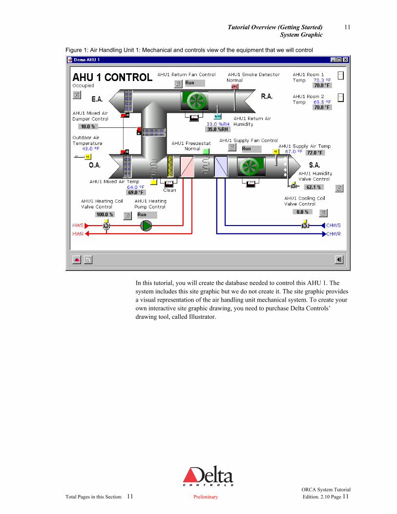
System Graphic The system included in this tutorial is a constant volume air handling unit with a supply and return fan. This type of system is sometimes called a H style air handler with constant volume. The Air Handling Unit (AHU) serves a large room which has two room temperature sensors. Figure 1 shows a graphic for this type of system. The graphic provides a mechanical view of an air handling unit and also includes some system information.
Tutorial Overview (Getting Started) System Graphic
ORCA System Tutorial
Total Pages in this Section: 11 Preliminary Edition. 2.10 Page 11
11
Figure 1: Air Handling Unit 1: Mechanical and controls view of the equipment that we will control
In this tutorial, you will create the database needed to control this AHU 1. The system includes this site graphic but we do not create it. The site graphic provides a visual representation of the air handling unit mechanical system. To create your own interactive site graphic drawing, you need to purchase Delta Controls’ drawing tool, called Illustrator.

Create an Air Handling Unit Database L1 Reviewing the Control System Definition Process
ORCA System Tutorial Edition. 2.10 Page 12 Preliminary Total Pages in this Section: 73
12
Lesson 1 – L1 REVIEWING THE CONTROL SYSTEM DEFINITION PROCESS
This lesson reviews the process used to define the AHU1 control system by presenting a predefined sequence of operations, a predefined points list and a list of properly named objects. A control system consists of the controller hardware and software programs that work together to control the systems in your facility.
For the tutorial, you will use the Complete List of Named Objects table, located on page 19 at the end of this lesson, to create the necessary objects.
In your work situation, you can use the basic process presented in this lesson to systematically define a control system. Essentially, you collect up relevant information, develop a sequence of operations and then create and refine a points list until you have a complete list of named objects.
In this lesson, you will learn how to do the following: Develop a sequence of operations. Name software objects according to a convention. Create a list of required software objects.
Introduction Typically, a basic design exists in the engineering and specifications documentation. Before you create a database for the system, you first need to interpret and clear up any ambiguities in this information.
The general process used to define the control system consists of the following steps: 1 Define Sequence of Operations from specification information such as
engineering documents, and drawings. 2 Define Initial I/O List. 3 Define Other Software Objects after completing the I/O objects list. 4 Define a complete list of properly named objects.
Creating Points List You need to define a complete list of objects required for a control system. For this tutorial, the control system consists of all the sensors and control devices required to control an AHU that serves one large room with two temperature sensors. First, an I/O points list is made from the engineering specifications and then other objects are added based on the Sequence of Operations.
L1 Reviewing the Control System Definition Process Creating Points List
ORCA System Tutorial
Total Pages in this Section: 73 Preliminary Edition. 2.10 Page 13
13
Objects are the individual software modules that monitor and control Facility equipment. Each type of object does a specific function. Common objects include Analog Inputs, Binary Inputs, Analog Outputs, Binary Outputs, Events (Alarms), Schedules and Multi-Trends.
Objects have properties such as a value and can interact with other objects. A controller has many objects of the same type. For example, you would expect a site to have many inputs and outputs. Objects are created and manipulated using Navigator.
Navigator is the object management interface of the ORCAview Operator Work Station (OWS). It provides control and visualization of complex facility systems by presenting the building system components as a group (or groups) of objects. Navigator has a similar look and feel to the Windows Explorer application created by Microsoft.
Define Sequence of Operations Defining the Sequence of Operations is a crucial step in the design process. You must clearly define the operating sequence for the Air Handling Unit and all its related equipment before beginning any programming.
Usually, the sequence of operations is defined from the specification. In this tutorial, you create the database for the following sequence.

Create an Air Handling Unit Database L1 Reviewing the Control System Definition Process
ORCA System Tutorial Edition. 2.10 Page 14 Preliminary Total Pages in this Section: 73
14
1. Sequence of Operations: Air Handling Unit 1 - AHU1 2 .
3. Start-up Mode
4.
5. The Supply and Return fans will be started according to the Weekly Schedule and Optimal Start.
6. Both fans must be shut down in the event of a freezestat or smoke detector trip.
7. The Weekly Schedule is as follows:
8. Mon Tue Wed Thur Fri Sat Sun
9. On 07:30 07:30 07:30 07:30 07:30 Off Off
10. Off 17:30 17:30 17:30 17:30 17:30 Off Off
11. The fans will not run during holidays, except as needed to maintain the Night Setback Temperature.
12.
13. Morning Warm-Up / Precool
14.
15. The optimal starting time will be automatically calculated each day to bring on the equipment prior to the Occupied Period.
16. During a heating start, the Mixed Air Dampers will be closed.
17.
18. Occupied Mode
19.
20. Occupied Mode exists once the Supply Fan is proven and the Weekly Schedule is ON.
21. The Supply Air Temperature Setpoint shall be adjusted between 55ºF and 75ºF depending on the current space conditions.
22. Mixed Air Dampers will modulate between Minimum and 100% to maintain the Mixed Air Temperature Setpoint.
23. Minimum shall be set at 10%, but be Operator adjustable.
24. Once mechanical cooling is active, the Mixed Air Dampers shall be set to Minimum.
25. The Mixed Air Temperature Setpoint shall be maintained at the Supply Air Temperature Setpoint minus 3ºF for fan pickup.
26. The Heating Coil Valve is modulated to maintain the desired Supply Air Temperature Setpoint.
27. The Heating Coil Pump will run when the Heating Coil Valve reaches 10% open and will stop when the Heating Coil Valve reaches 0%.
28. The Cooling Coil Valve is modulated to maintain the desired Supply Air Temperature Setpoint.
29. The Humidity Control Valve will be modulated to maintain the Return Air Humidity setpoint when the Outdoor Air Temperature is below 45ºF.
30. The Return Air Humidity Setpoint will be adjusted between 10% and 35% based on Outdoor Air Temperature to prevent condensation.
31.

L1 Reviewing the Control System Definition Process Creating Points List
ORCA System Tutorial
Total Pages in this Section: 73 Preliminary Edition. 2.10 Page 15
15
32. Unoccupied Mode
33.
34. The system will normally be held in Shutdown Mode during the unoccupied period.
35. If the Space Temperature drops below 60ºF or rises above 85ºF, the Fans will be restarted to maintain the Night Setback Temperature.
36. The Night Setback Temperature will be 60ºF in Winter and 85ºF in Summer.
37.
38. Shutdown Mode
39.
40. Supply Fan Stops.
41. Return Fan Stops.
42. Mixed Air Dampers are closed.
43. Heating Coil Valve and Heating Coil Pump are utilized to ensure the Mixed Air Temperature does not drop below 40ºF.
44.
45. Alarms
46.
47. Supply Fan Failure.
48. Return Fan Failure.
49. Supply Air Temperature 5ºF above or below Supply Air Temperature Setpoint.
50. Mixed Air Temperature below 40ºF.
51. Freezestat Trip.
52. Smoke Detector Trip.
53. Dirty Filter Alarm.
54. Room Temperature 3ºF above or below desired Room Temperature Setpoint.
55.
Define I/O List After you review the system drawing, control system specification, and Sequence of Operations, you would make an initial Input/ Output (I/O) object list. You may determine that some necessary objects are omitted from the specification or the system drawing.

Create an Air Handling Unit Database L1 Reviewing the Control System Definition Process
ORCA System Tutorial Edition. 2.10 Page 16 Preliminary Total Pages in this Section: 73
16
Define I/O Objects From the Air Handling Unit 1 system graphic on page 11, the following I/O objects are required.
Initial I/O Objects List Inputs I/O
Number Outputs
AHU1 Supply Fan Status (binary) 1 AHU1 Supply Fan Control (binary)
AHU1 Return Fan Status (binary) 2 AHU1 Return Fan Control (binary)
AHU1 Supply Air Temp (analog) 3 AHU1 Mixed Air Damper Control (analog)
AHU1 Mixed Air Temp (analog) 4 AHU1 Heating Coil Valve Control (analog)
AHU1 Return Air Humidity (analog)
5 AHU1 Heating Pump Control (binary)
AHU1 Freezestat (binary) 6 AHU1 Cooling Coil Valve Control (analog)
AHU1 Smoke Detector (binary) 7 AHU1 Humidity Valve Control (analog)
AHU1 Filter Status (binary) 8 (not used)
AHU1 Room 1 Temp (analog) 9 (not used)
AHU1 Room 2 Temp (analog) 10 (not used)
(not used) 11 (not used)
AHU1 Outdoor Air Temp (analog) 12 (not used)
After the initial list of I/O objects is made, the Sequence of Operations is reviewed to determine if additional I/O objects are required.
Define Other Software Objects After listing the required I/O objects, you would then list the other required objects. This is an involved task as there are many options and possible combinations of objects.
Method The best method for defining the required objects is to read the Sequence of Operations and find the user adjustable setpoints. Each setpoints requires an Analog Variable object in a database. Typically, each Analog Input will require a setpoint. Next, read the specifications or Sequence of Operations and search for occurrences of Schedules, Calendars, Control Loops, and other objects.

L1 Reviewing the Control System Definition Process Creating Points List
ORCA System Tutorial
Total Pages in this Section: 73 Preliminary Edition. 2.10 Page 17
17
Objects Defined by Sequence of Operations From a review of the sequence of operations, we would add the following objects:
Initial Other Objects List Sequence of Operation Line #
Object Required Reason
5, 7-11, 20 Schedule Start according to Weekly Schedule.
5, 13, 15, 16 Optimum Start Start of Supply and return fans. Heating start.
5, 13, 15 Optimum Start Start of Supply and return fans. Cooling start.
11 Calendar Holiday Calendar.
13, 15, 18, 20, 32, 38 Multi-State Variable Occupancy Mode with the following 6 states defined in an MIC:
Occupied, Unoccupied, Warmup, Precool, Night_Heating and Night_Cooling. Use with Occupancy MV.
22 Control Loop Modulation of Mixed Air Damper.
26 Control Loop Modulation of Heating Coil Valve.
28 Control Loop Modulation of Cooling Coil Valve.
29 Control Loop Modulation of Humidity Control Valve.
Define Additional Objects The previous list is a good starting point from which to build a more complete list. You would add objects to the Initial Other Objects list and create a more complete list. The Additional Other Objects list includes other objects and gives the reasons for including each.
Note: Not all the objects can be readily determined from the system drawing or the Sequence of Operations. Some specifications list the objects that the engineer thinks are necessary but the list should be used as a guide only. Some required objects can only be determined through creating and programming the database.
Sometimes, you may create an Analog or Binary Variable rather than use a constant entered in a program. This approach makes it easier to adjust a constant that is used for calculations in a program.

Create an Air Handling Unit Database L1 Reviewing the Control System Definition Process
ORCA System Tutorial Edition. 2.10 Page 18 Preliminary Total Pages in this Section: 73
18
Additional Other Objects List
Object Required Reason Analog Variable Value for a Supply Air Temperature Setpoint.
Analog Variable Value for a Mixed Air Temperature Setpoint.
Analog Variable Value for a User Adjustable AHU1 Return Air Humidity Setpoint.
Analog Variable User Adjustable Room 1 Temperature Setpoint.
Analog Variable User Adjustable Room 2 Temperature Setpoint.
Analog Variable AHU1 Minimum Damper Position.
Analog Input Configuration
For a 10k thermistor temperature sensor.
Analog Input Configuration
For RH Sensor input.
Analog Output Configuration
For a 2-10V signal actuator.
Binary Device Configuration
Dirty / Clean indication of Filter Switch Input.
Binary Totalizer Not specified but a good idea. For Supply Fan.
Binary Totalizer Not specified but a good idea. For Return Fan.
Trend Logs Create Trend Logs of Inputs, Outputs, and setpoints etc. when the GCL+ programming is finished.
Multi-Trends Create Multi-Trends of groups of up to 8 related Trend logs when the GCL+ programming is finished.
Events (Alarms) Create Events to monitor analog or binary values when the GCL+ programming is finished.
Naming Conventions for Objects A good naming scheme ensures that objects are named consistently and that their overall function and relation to other objects is clear across a site.
It is no longer necessary to use acronyms and underscores to form names. A valid name can be up to 60 character long and include spaces. A name is usually from 15 to 30 characters long and is case-sensitive.
Delta Controls recommends the following naming convention.

L1 Reviewing the Control System Definition Process Creating Points List
ORCA System Tutorial
Total Pages in this Section: 73 Preliminary Edition. 2.10 Page 19
19
To name an object: 1 Put an acronym of the system name as a prefix (i.e. AHU1 ) with a space at
the end of the prefix. 2 Describe the specific device or object in the system in full (e.g.
AHU1 Mixed Air Controller). 3 Add a suffix following the name that indicates the overall function of the
object. Examples include Control, Status, Setpoint, Alarm, Program, or Totalizer
4 If one object refers to another, add the object acronym after the name. (e.g. TL, MT, AIC, AOC, BDC, MIC) following the name such as AHU1 Mixed Air Control TL or Running / Stopped BDC.
Define Complete List of Named Required Objects Now that we have a list of required objects, we would make consistent names for them. Use the following table as a guide for naming the objects. The table extends over three pages.
Create Object References When a new object is created, the system requires an Object Reference (System Number) . Often when you enter the Type of Object, the dialog box automatically assigns an Object Reference. However, sometimes you must type the Object Reference information as shown in Figure 6 Object Reference Definition on page 40.
The object reference is made as follows: Controller Address, Object Type and Number. For example, 100.EV13 indicates Event object 13 on controller 100.
This table lists the named objects that we will create in the database to control the Air Handling Unit (AHU). The initial default file that we use to start the database contains the configuration objects needed for the tutorial.
Starting with Lesson 5 – Creating Input and Output Objects, the tutorial will include parts of this table as we create different types of objects. We will start with the objects related to input and output operations.
Object Name Type Object Reference
Configuration Objects
Temperature 10K -35-240 degF AIC
analog AIC4
Temperature 10K -40-150 degC AIC
analog AIC5
Humidity 4-20mA 0-100 %RH AIC
analog AIC7
Belimo 2-10 VDC Output AOC analog AOC1
Running / Stopped BDC binary BDC1
Flow / No Flow BDC binary BDC2
Dirty / Clean BDC binary BDC3

Create an Air Handling Unit Database L1 Reviewing the Control System Definition Process
ORCA System Tutorial Edition. 2.10 Page 20 Preliminary Total Pages in this Section: 73
20
Object Name Type Object Reference
Freeze / Normal BDC binary BDC4
Smoke / Normal BDC binary BDC5
Run / Stop BDC binary BDC6
On / Off BDC binary BDC7
Occupied / Unoccupied BDC binary BDC8
Occupancy MIC multi-state MIC1
Inputs AHU1 Supply Fan Status binary BI1
AHU1 Return Fan Status binary BI2
AHU1 Supply Air Temp analog AI3
AHU1 Mixed Air Temp analog AI4
AHU1 Return Air Humidity analog AI5
AHU1 Freezestat binary BI6
AHU1 Smoke Detector binary BI7
AHU1 Filter Status binary BI8
AHU1 Room 1 Temp analog AI9
AHU1 Room 2 Temp analog AI10
AHU1 Outdoor Air Temp analog AI12
Outputs AHU1 Supply Fan Control binary BO1
AHU1 Return Fan Control binary BO2
AHU1 Mixed Air Damper Control analog AO3
AHU1 Heating Coil Valve Control analog AO4
AHU1 Heating Pump Control binary BO5
AHU1 Cooling Coil Valve Control analog AO6
AHU1 Humidity Valve Control analog AO7
Setpoints AHU1 Supply Air Temp Setpoint analog AV1
AHU1 Mixed Air Temperature Setpoint
analog AV2
AHU1 Return Air Humidity Setpoint
analog AV3
AHU1 Room 1 Temp Setpoint analog AV4
AHU1 Room 2 Temp Setpoint analog AV5

L1 Reviewing the Control System Definition Process Creating Points List
ORCA System Tutorial
Total Pages in this Section: 73 Preliminary Edition. 2.10 Page 21
21
Object Name Type Object Reference
AHU1 Minimum Damper Position analog AV9
AHU1 Occupancy multi-state MV1
PID Controllers AHU1 Mixed Air Controller N/A CO1
AHU1 Heating Valve Controller N/A CO2
AHU1 Cooling Valve Controller N/A CO3
AHU1 Humidification Controller N/A CO4
Schedules and Calendars
AHU1 Weekly Schedule N/A SCH1
AHU1 Holiday Calendar CAL1
Optimum Start AHU1 Heating Optimum Start N/A OS1
AHU1 Cooling Optimum Start N/A OS2
Totalizers AHU1 Supply Fan Totalizer binary BT1
AHU1 Return Fan Totalizer binary BT2
Trend Logs
as required
Multi Trends
as required
Events
AHU1 Supply Fan Alarm Command Failure
EV1
AHU1 Return Fan Alarm Command Failure
EV2
AHU1 Supply Air Temp Alarm Out of Range
EV3
AHU1 Mixed Air Temp Alarm Out of Range
EV4
AHU1 Return Air Humidity Alarm Out of Range
EV5
AHU1 Freezestat Alarm Change of State
EV6
AHU1 Smoke Detector Alarm Change of State
EV7

Create an Air Handling Unit Database L1 Reviewing the Control System Definition Process
ORCA System Tutorial Edition. 2.10 Page 22 Preliminary Total Pages in this Section: 73
22
Object Name Type Object Reference
AHU1 Filter Alarm Change of State
EV8
AHU1 Room 1 Temperature Alarm
Floating Limit
EV9
AHU1 Room 2 Temperature Alarm
Floating Limit
EV10
Moving On You have completed this lesson. This lesson reviewed the process used to create and refine a list of objects from the specification and Sequence of Operations information.

L2 Reviewing the Hardware Definition and Setup Process Selecting Controller Hardware for the Tutorial System (DSC-1212E)
ORCA System Tutorial
Total Pages in this Section: 73 Preliminary Edition. 2.10 Page 23
23
Lesson 2 – L2 REVIEWING THE HARDWARE DEFINITION AND SETUP PROCESS
This lesson explains the process used to select and prepare the required hardware needed for the Air Handling Unit application of the tutorial.
In this lesson, you will learn how to do the following: Follow a process based on four factors to select the hardware needed for the
application.
Selecting Controller Hardware for the Tutorial System (DSC-1212E)
In a real-world project, you would need to select the types of controllers needed for different parts of a project based on the requirements defined in the points list. The following section explains why the DSC-1212E was selected for this tutorial.
The AHU control system requires: 6 Analog Inputs and 5 Binary Inputs for a total of 11 inputs. 4 Analog Outputs and 3 Binary Outputs for a total of 7 outputs. When choosing the best controller for the tutorial system, consider the following four factors: 1 I/O Requirements:
11 inputs and 7 outputs are required. Some expansion I/O should be allowed.
2 Standalone Application requiring accurate clock time Air Handlers are typically scheduled and need to operate independently if
the network fails. A Delta System Controller has a system clock and can operate independent of the network.
3 Subnetwork Support Required This Air Handler tutorial does not require an RS-485 sub-network for
terminal units. Some applications would use MS/TP and/ or LINKnet devices.
4 Programmability Required Air Handlers require the flexibilty of programming to be adequately
controlled. A Delta System Controller is programmable. Based on these four factors, a Delta System Controller such as a 12x12 would handle this application. In some situations, you might consider using a DSC-1616 to allow for future expansion or modification to the control system.

Create an Air Handling Unit Database L2 Reviewing the Hardware Definition and Setup Process
ORCA System Tutorial Edition. 2.10 Page 24 Preliminary Total Pages in this Section: 73
24
Description of a DSC Controller The Delta 12x12 Controller is a Native BACnet System Controller that is fully programmable (via GCL+) and communicates on an RS-485 LAN using the MS/TP BACnet protocol, or optionally over Twisted-Pair Ethernet (10BaseT). The controller includes an easy to mount enclosure.
Figure 2: Delta DSC-1212E Controller
The DSC-1212E is designed for a wide range of applications requiring no more than 12 inputs and 12 outputs, including but not limited to Roof Top Units, Air Handlers, Boilers or Chillers. A second RS-485 port may be configured as an MS/TP SubLAN or a LINKnet network that supports up to 12 Delta BACstats or other Delta LINKnet devices.
The 12 universal inputs are jumper configurable and the 12 analog outputs are available with optional Hand-Off-Auto (HOA) switches.
OUT PUT S
I NPUT S

L2 Reviewing the Hardware Definition and Setup Process Selecting Controller Hardware for the Tutorial System (DSC-1212E)
ORCA System Tutorial
Total Pages in this Section: 73 Preliminary Edition. 2.10 Page 25
25
Board Layout (DSC-1212E) Figure 3: DSC-1212E Board Layout, shows a simplified board layout diagram for a DSC-1212E controller.
Figure 3: DSC-1212E Board Layout
32
14
58
76
910
1112
OP7
GND
OP8
GND
OP9
GND
OP10
GND
OP11
GND
OP12
GND
32
14
58
76
910
1112
OP1
GND
OP2
GND
OP3
GND
OP4
GND
OP5
GND
OP6
GND
AUTO OFF HAND
AUTO OFF HAND
SERVICE PORT
21 24~
GND
POWER
PWR
-
RX
TXNET1
+
21 R
S485
POWER
SCAN
CLEAR
TX
GND
RX
DTR
DCD
2 Amp 2 Amp
GROUND
IP1
GND
32
14
58
76
910
1112
IP2
GND
IP3
GND
IP4
GND
IP5
GND
IP6
GND
IP7
GND
32
14
58
76
910
1112
IP8
GND
IP9
GND
IP10
GND
IP11
GND
IP12
GND
ETHERNET
ADDRESS
12
34
56
78
+
ON OFF
DNA
On
64
32
16
8
4
21
RUN AREASYSTEMSUBNET
+
12TX
RXNET2
12
POWER
PWR
RS4
85
-
24~
GND
DSC-1212E
32
1
RS2
32
45
4-20mA 10k 5V 10V
4-20mA 10k 5V 10V
4-20mA 10k 5V 10V
4-20mA 10k 5V 10V
4-20mA 10k 5V 10V
4-20mA 10k 5V 10V
4-20mA 10k 5V 10V
4-20mA 10k 5V 10V
4-20mA 10k 5V 10V
4-20mA 10k 5V 10V
4-20mA 10k 5V 10V
4-20mA 10k 5V 10V
Moving On You have completed this lesson which reviews the process for selecting the controller hardware.
OUT PUT S
I NPUT S

Create an Air Handling Unit Database L3 Preparing the Hardware and Software
ORCA System Tutorial Edition. 2.10 Page 26 Preliminary Total Pages in this Section: 73
26
Lesson 3 – L3 PREPARING THE HARDWARE AND SOFTWARE
This lesson explains how to prepare and connect the DSC-1212E controller to the Operator Workstation. When these preparations are done, you can log into ORCAview.
In this lesson, you will learn how to do the following: Prepare and configure hardware and software. Connect power, communications and sensor inputs to a DSC controller. Log into ORCAview using an Ethernet connection to the DSC-1212E
controller.
Preparing Your Hardware Before you create the objects and write programs for this system, you must prepare the controller hardware. These initial preparations must be done before you can start to create a database.
Caution: Set the controller address before clearing the database to ensure that all the default object names are reset to include the new address. Set the address with the power turned off as the change in address only takes effect when the power is reset or a software reset command is issued.
The following outlines the steps that are covered in details in the remainder of this lesson. Before you communicate with the controller using ORCAview, you will do the following: a. Address the controller. b. Clear any database that may be in the controller using the RUN / Clear
jumpers. c. If necessary, connect the controller hardware. d. Connect power to the DSC-1212E controller. e. If necessary, attach a Delta Controls USB or Parallel Port Software Key. f. If necessary, install the Sentinel Drivers which work with the software key. g. If necessary, install the Operator Workstation. h. Start ORCAview.

L3 Preparing the Hardware and Software Preparing Your Hardware
ORCA System Tutorial
Total Pages in this Section: 73 Preliminary Edition. 2.10 Page 27
27
Figure 4 shows a top view of the bottom third of the DSC controller with the RUN/CLEAR jumper and the Address switches emphasized.
Figure 4: DSC-1212 Jumpers and Switches: Bottom Third of the Controller
32
14
58
76
910
1112
OP7
GND
OP8
GND
OP9
GND
OP10
GND
OP11
GND
OP12
GND
AUTO OFF HAND
CLEARGROUND
IP7
GND
32
14
58
76
910
1112
IP8
GND
IP9
GND
IP10
GND
IP11
GND
IP12
GND
ADDRESS
12
34
56
78
+
ON OFF
DNA
On
64
32
16
8
4
2
1
RUN AREASYSTEMSUBNET
4-20mA10k 5V 10V
4-20mA10k 5V 10V
4-20mA10k 5V 10V
4-20mA10k 5V 10V
4-20mA10k 5V 10V
4-20mA10k 5V 10V
Action: A: Address the controller
The DSC-1212 controller has DIP switches for setting the address.
A: To address the controller: 1 First, check that the power for the controller is disconnected. 2 Then, determine the address of the controller. The address for this tutorial is
100. 3 Locate the ADDRESS switches that are on the bottom middle of the DSC-
1212. Each ADDRESS switch controls the value of a binary digit. See Figure 4: DSC-1212 Jumpers and Switches.
4 Set the address of the controller by changing the positions of the ADDRESS DIP switches as indicated in Figure 5 to set the address to 100. For an address of 100, set just the first DIP switch labeled 1 to the ON position. The address on the DIP switches is multiplied by 100.

Create an Air Handling Unit Database L3 Preparing the Hardware and Software
ORCA System Tutorial Edition. 2.10 Page 28 Preliminary Total Pages in this Section: 73
28
Figure 5: Address DIP Switches with DIP 1 ON; Address = 100
ON
OFF
OFF
OFF
OFF
OFF
OFF
1
2
4
8
16
32
64
OFFON
In the previous Figure 5 Address DIP Switches, the digit values are indicated to the left, beside the DIP switch package. The address is the sum of all the DIP switches set to the ON position as indicated at the top of the DIP switch package multiplied by 100 for System Controllers. The maximum address that can be set is 9900 (DIP switch 99 * 100).
Action: B: Clear the database The DSC-1212 controller has a RUN/ CLEAR jumper for clearing the database.
B: To clear a database from the battery-backed memory of a Delta controller: 1 Check that the 24 VAC power is disconnected. 2 Locate the RUN/CLEAR jumper. Look towards the lower left side of the
DSC-1212 controller board. Refer to Figure 4: DSC-1212 Jumpers and Switches.
3 Put the RUN/CLEAR jumper in the CLEAR position for three or more seconds.
4 Put the RUN/CLEAR jumper back to the RUN position.
Connecting Controller Hardware You need to connect power, communications and peripherals to the hardware. This section describes the connection of the power port and Ethernet port. The Installation Sheets for the respective products provide additional technical information.
Optional Connections You can connect a temperature sensor, current sensor and actuator to the DSC-1212E controller for the tutorial. Although these connections are not necessary, they will make the tutorial easier to follow.
L3 Preparing the Hardware and Software Connecting Controller Hardware
ORCA System Tutorial
Total Pages in this Section: 73 Preliminary Edition. 2.10 Page 29
29
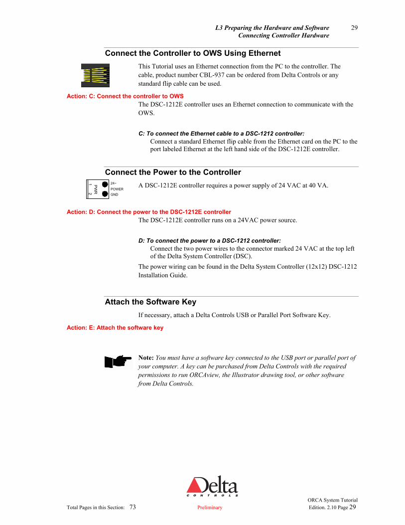
Connect the Controller to OWS Using Ethernet This Tutorial uses an Ethernet connection from the PC to the controller. The cable, product number CBL-937 can be ordered from Delta Controls or any standard flip cable can be used.
Action: C: Connect the controller to OWS The DSC-1212E controller uses an Ethernet connection to communicate with the OWS.
C: To connect the Ethernet cable to a DSC-1212 controller: Connect a standard Ethernet flip cable from the Ethernet card on the PC to the
port labeled Ethernet at the left hand side of the DSC-1212E controller.
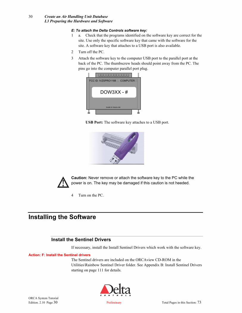
Connect the Power to the Controller A DSC-1212E controller requires a power supply of 24 VAC at 40 VA.
Action: D: Connect the power to the DSC-1212E controller The DSC-1212E controller runs on a 24VAC power source.
D: To connect the power to a DSC-1212 controller: Connect the two power wires to the connector marked 24 VAC at the top left
of the Delta System Controller (DSC). The power wiring can be found in the Delta System Controller (12x12) DSC-1212 Installation Guide.
Attach the Software Key If necessary, attach a Delta Controls USB or Parallel Port Software Key.
Action: E: Attach the software key
Note: You must have a software key connected to the USB port or parallel port of your computer. A key can be purchased from Delta Controls with the required permissions to run ORCAview, the Illustrator drawing tool, or other software from Delta Controls.
21 24~
GNDPOWER
PW
R
Create an Air Handling Unit Database L3 Preparing the Hardware and Software
ORCA System Tutorial Edition. 2.10 Page 30 Preliminary Total Pages in this Section: 73
30
E: To attach the Delta Controls software key: 1 a. Check that the programs identified on the software key are correct for the
site. Use only the specific software key that came with the software for the site. A software key that attaches to a USB port is also available.
2 Turn off the PC. 3 Attach the software key to the computer USB port to the parallel port at the
back of the PC. The thumbscrew heads should point away from the PC. The pins go into the computer parallel port plug.
MADE IN THAILAND
DOW3XX - #
FCC ID: IVZSPRO1188 COMPUTER
USB Port: The software key attaches to a USB port.
Caution: Never remove or attach the software key to the PC while the power is on. The key may be damaged if this caution is not heeded.
4 Turn on the PC.
Installing the Software
Install the Sentinel Drivers If necessary, install the Install Sentinel Drivers which work with the software key.
Action: F: Install the Sentinel drivers The Sentinel drivers are included on the ORCAview CD-ROM in the Utilities\Rainbow Sentinel Driver folder. See Appendix B: Install Sentinel Drivers starting on page 111 for details.

L3 Preparing the Hardware and Software Installing the Software
ORCA System Tutorial
Total Pages in this Section: 73 Preliminary Edition. 2.10 Page 31
31
Installing Operator Workstation (OWS) Assuming that you have your hardware prepared and connected to your PC, then you need to confirm that ORCAview is installed on your computer.
Action: G: Install the ORCAview OWS software If necessary, install ORCAview. See the Quick Install of ORCAview section in Appendix C – Install ORCAview OWS starting on page 114 for details.
Log Into ORCAview Assuming that you have your hardware prepared and connected to your PC, log into ORCAview.
Action: H: Start ORCAview OWS You are ready to log into ORCAview.
H: To start ORCAview: You can start ORCAview from the ORCAview icon on the desktop. Double
click on the icon to start ORCAview. The characters for the Username and Password are always capital letters.
Type in your Username and Password.
If problems occur, recheck all the connections. Ensure that the Ethernet communications port selected in the ORCAview Connect using field of the Logon dialog is correct.
Moving On You have completed this lesson. You have installed and configured the hardware and software. You have done an ORCAview login.

Create an Air Handling Unit Database L4 Working with Objects in Navigator
ORCA System Tutorial Edition. 2.10 Page 32 Preliminary Total Pages in this Section: 73
32
Lesson 4 – L4 WORKING WITH OBJECTS IN NAVIGATOR
Now, that you have logged into ORCAview, this lesson explains the basics of the Navigator Window. With Navigator, you can create and configure objects. Objects are the individual software modules that monitor and control facility equipment.
In this lesson, you will learn how to do the following: View the objects on a site Load a database Save a database
Description of Navigator Delta Controls’ Navigator window lets you view and control a complex facility system. Navigator is the object management interface of the OWS (Operator Work Station). It presents the building system components as a group (or groups) of objects. This interface is similar to the Microsoft Windows Explorer application.
This lesson covers just the basics needed to complete the tutorial using the Navigator Window and to a lesser degree the ORCAview Main Toolbar (Dashboard).
The ORCAview Main Toolbar (Dashboard) and Navigator are shown on the Windows desktop in the following figure:
Navigator Window
ORCAview Main Toolbar

L4 Working with Objects in Navigator Description of Navigator
ORCA System Tutorial
Total Pages in this Section: 73 Preliminary Edition. 2.10 Page 33
33
Typically, the main toolbar is docked at the top of the screen and appears when you move your cursor near the top of the screen.
If Navigator window is not open, you can start Navigator by selecting Tools in the ORCAview Dashboard and then clicking Navigator. You could also click the Navigator button on the toolbar located on the ORCAview Dashboard.
The Navigator window lets you do the following tasks: Create and edit objects for a control system. Save and load control system databases. View your system. Monitor and control equipment. Create and modify system control sequences. Respond to Events (Alarms) using Active Alarms view. More information can be obtained by pressing F1 in the Navigator window. You can also refer to Chapter 3 Working with Objects Using Navigator in the ORCAview Operator Guide or Chapter 3 Navigator in the ORCAview Technical Reference manual.

Create an Air Handling Unit Database L4 Working with Objects in Navigator
ORCA System Tutorial Edition. 2.10 Page 34 Preliminary Total Pages in this Section: 73
34
Components of the Navigator Window The Navigator window is divided into two panes. The left pane shows the available controllers in the network. The right pane shows the contents of a specific controller which is selected in the left pane.
Components: Left Pane-Network Tree The Navigator left pane includes a network tree that has icons representing networks, protocols and the connected devices including controllers and the OWS. The following table explains the icons that may display in the Navigator left pane.
NAVIGATOR LEFT PANE ICONS Icon Item Meaning
Delta Network The top of a network at the current site.
Protocol The communications protocol that connects the
controllers.
Local ORCAview PC The local PC with the ORCAview software.
Remote ORCAview PC A remote PC on the network with the ORCAview software.
Controller A Delta Control Unit, programmable Zone Controller, Plus Panel, Turbo or Mini-Turbo Panel, Micro Panel.
BACnet VAV or VVT Zone Controller
A Version 3 VAV or VVT Room Controller such as a DAC-322 or DAC-304.
BACstat I A device that acts as a temperature sensor on MS/TP.
Left Pane Right Pane

L4 Working with Objects in Navigator Components of the Navigator Window
ORCA System Tutorial
Total Pages in this Section: 73 Preliminary Edition. 2.10 Page 35
35
NAVIGATOR LEFT PANE ICONS Icon Item Meaning
BACstat II A device that acts as a temperature sensor on MS/TP
or LINKnet networks. Also could be a Zone controller.
3rd Party Controller A BACnet controller supplied by another vendor.
BACnet Room Controller A Version 3 Room Controller such as a DAC-T305.
HVAC Delta Application Controller (Medium Enclosure, Red PCB)
A medium Controller such as a DAC-606.
HVAC Delta System Controller (Large Enclosure, Red PCB)
A large HVAC DSC controller such as DSC-1616/DSC-1212/DSC-1280.
Lightning Controller (Green PCB)
A Lighting Controller such as DLC-G1212/DLC-D1212
Access Delta System Controller (Medium Enclosure, Blue PCB)
An Access Controller such as ASM-24X/24EX.
In the previous table, a small red triangle in the lower right area of an icon indicates the presence of a system clock on the device. For example, the last entry in the previous table for the Access Delta System Controller has a triangle indicating that it has a system clock.
The Active Alarms Folder generally contains all the active alarms at the site. The Active Alarms folders can appear in two different ways.
Active Alarms Folder
Meaning
When no active alarms are present, the active alarms folder appears as on the left.
When active alarms are present, the Active Alarms folder appears with a large red alarm icon as on the left. Open the folder to view or acknowledge active alarms.
Graphic Folder Meaning
The Graphics folder contains the site graphics.

Create an Air Handling Unit Database L4 Working with Objects in Navigator
ORCA System Tutorial Edition. 2.10 Page 36 Preliminary Total Pages in this Section: 73
36
Components: Right Pane-Controller Objects When any network device is selected in the Navigator left pane, the Navigator right pane displays the objects in the device. Typical objects in a controller include Events (Alarms), inputs, outputs, Trend Logs, and Schedules. Each object type has its own symbol or icon to distinguish it from other objects.
Use Network Tree (Left Pane) - Mouse Commands The left pane of the Navigator window shows the Delta Controls network. Right clicking on a controller in the left pane provides this command list.
Load a Database A database refers to a file that contains all of the objects from a particular controller. Database files have a .pdb file extension. Each database is specific to a particular controller in the network.
To load a database:
Caution: This load procedure will replace and copy over the database already existing in the controller.
1 Select the controller in the left hand Navigator pane. 2 Right click and choose Load. 3 Select the controller database file that you want to load. 4 Click Open. The database is loaded into your controller.
Save a Database Databases should be saved whenever a change is made so that a current backup database always exists for all of the controllers.

L4 Working with Objects in Navigator Components of the Navigator Window
ORCA System Tutorial
Total Pages in this Section: 73 Preliminary Edition. 2.10 Page 37
37
To save a database for a single controller: 1 Select the controller in the left pane of Navigator. 2 Right click and choose Save As. 3 Type in a suitable File name and press Enter. The file is saved in the Site
folder. Delta Controls suggests that the name of the file contain the date and the controller address.
Load Default Database An initial database is included on the CD-ROM so that it is easier to complete the tutorial. This database contains the necessary configuration objects (AIC, AOC, BDC, MIC) required for the tutorial. You would load this file, and use it as the starting point for the tutorial.
Action: Load the default database
To load the default database: Load the default_database.pdb database from the CD-ROM. See the previous section Load a Database on page 36.
Note: It is recommended that you use a default database file such as default_database.pdb to start a new database. This approach standardizes the configuration objects and saves time as you use existing AIC, AOC, BDC and MIC objects instead of creating your own for each new project.
When you load in the default database, the name of the controller in the left pane changes to match the name specified in the Device (DEV) object. The configuration objects are loaded in but do not display as they are system objects. System objects are needed for setup but are not normally needed for day-to-day operation of the system.
By default system objects are hidden. The Filter Icon in the lower right corner of the Navigator window gives the user three options:
Option Filter Icon Hide System Objects
Show Only System Objects
Show All
Right click on the filter icon in the lower right corner of the Navigator window. Select Show All.

Create an Air Handling Unit Database L4 Working with Objects in Navigator
ORCA System Tutorial Edition. 2.10 Page 38 Preliminary Total Pages in this Section: 73
38
Set the Controller Time and Date You should set the controller time and date before proceeding with the database creation. This ensures that the controller has the correct time.
Action: Set Panel Time The time is set in the ORCAview dashboard in the Tools pop-up menu. Select the Set Panel Time option.
Name the Controller We can name the controller in the left pane so that the controller function is clear.
Action: Name your controller
To name a controller: 1 Select the controller in the left side pane of the Navigator window. 2 Right click and select Open. 3 On the Description tab, type AHU1 Control in the Name field. Click OK.
Moving On You have completed this lesson. For information on additional features of Navigator, see Chapter 3 Navigator PDF file of the Technical Reference manual. Additionally, you can press the F1 Key on a field and get specific help. Each software object has a ? Help button on the dialog in the lower right corner.
L5 Creating Input and Output Objects Introduction
ORCA System Tutorial
Total Pages in this Section: 73 Preliminary Edition. 2.10 Page 39
39
Lesson 5 – L5 CREATING INPUT AND OUTPUT OBJECTS
This lesson explains the basics of the creating and configuring objects such as input and outputs.
Facility equipment is monitored and controlled by individual software modules called objects. Each type of object does a specific function. Common objects include Analog Inputs, Binary Inputs, Analog Outputs, Binary Outputs, Events (Alarms), Schedules and Multi-Trends.
Objects have properties such as a value and can interact with other objects. A controller has many objects of the same type. For example, you would expect a site to have many inputs and outputs. Objects are created and manipulated using Navigator.
In this lesson, you will learn how to do the following: Create input and output objects. Create an object reference numbers. Create objects using a standard naming convention. Link one object to another. Configure input and output objects.
Introduction You usually create Input and Output objects first.
Inputs The Analog Input (AI) and the Binary Input (BI) objects are used to define and configure sensors that connect to the inputs on the controller. The sensors may be analog or digital. Each sensor requires a separate input object.
Analog Inputs generate a continuous range of values based on the sensor measurement. Typical analog sensors measure temperature, humidity, current, or pressure.
Binary Inputs have only two states. Typical digital sensors measure dry contact status for alarming or equipment status purposes. For example, a Freeze Thermostat is a two-state digital device that trips when the temperature in the duct becomes too cold. It indicates either a normal or freeze condition. This type of device would require a Binary Input.
Outputs The Analog Output (AO) and the Binary Output (BO) objects are used to provide control signals to output devices such as actuators that connect to the outputs on the controller. The output devices may be analog or digital. Each output device requires a separate output object.
Analog Outputs generate a continuous range of values based on the calculated control signal. Typical analog output devices include actuators.
Create an Air Handling Unit Database L5 Creating Input and Output Objects
ORCA System Tutorial Edition. 2.10 Page 40 Preliminary Total Pages in this Section: 73
40
Binary Outputs have only two states. Typical digital output devices provide RUN / STOP control for equipment. For example, a Binary Output might control a fan or pump.
Name Objects Using a Naming Convention A good naming scheme ensures that objects are named consistently and that their overall function and relation to other objects is clear across a site.
It is no longer necessary to use acronyms and underscores to form names. A valid name can be up to 60 character long and include spaces. A name is usually from 15 to 30 characters long and is case-sensitive.
Delta Controls recommends the following naming convention.
To name an object: 1 Put an acronym of the system name as a prefix (i.e. AHU1 ) with a space at
the end of the prefix. 2 Describe the specific device or object in the system in full (e.g.
AHU1 Mixed Air Controller). 3 Add a suffix following the name that indicates the overall function of the
object. Examples include Control, Status, Setpoint, Alarm, Program, Totalizer 4 If one object refers to another, add the object acronym after the name. (e.g.
TL, MT, AIC, AOC, BDC, MIC) following the name such as AHU1 Mixed Air Control TL or Running / Stopped BDC.
Create Object References (System Numbers) An Object Reference is required by the system when a new object is created. Often when you enter the Type of Object, the dialog box automatically assigns an Object Reference. However, sometimes you must type the Object Reference information as shown in Figure 6 Object Reference Definition.
Figure 6: Object Reference Definition
In the previous figure, 100.EV13 indicates Event object 13 on controller 100.
1 0 0 . E V 1 3
Controller Address
Object Type and Number

L5 Creating Input and Output Objects Creating the Inputs
ORCA System Tutorial
Total Pages in this Section: 73 Preliminary Edition. 2.10 Page 41
41
Link One Object to Another Many objects have fields that accept other objects and allow one object to be linked to another. For example, an Event (Alarm) needs to monitor another object such as an Input. An object must be specified in the Alarm Input field on the Setup tab of an Event.
There are several ways to provide this information that links one object to another: Enter an Object Reference such as 100.AI4 or if the object is on the local
controller, then just AI4 is fine. The field will change and displays the object name automatically.
Drag and drop an object from the Navigator window to the field on the dialog.
Paste or type in the complete name. It takes time to type in a long name of 15 to 30 characters and it is easy to make a mistake.
Creating the Inputs This section explains how to create the Input objects defined in the Complete List of Objects table located on page 19 All initial preparations of the software and hardware are now complete. Using Navigator, you create the objects.
Action: Create the Supply Fan Status Binary Input object This procedure directly covers the creation of only the Supply Fan Status Binary Input object. You must create the other Analog Inputs and Binary Inputs in the list.
Use the following procedure to create the Supply Fan Status Binary Input object.
To create an Input object: 1 Right click on any white space in the right hand pane of the Navigator
window. From the pop-up menu, select New.... at the top of the list. The Create Object dialog window appears.

Create an Air Handling Unit Database L5 Creating Input and Output Objects
ORCA System Tutorial Edition. 2.10 Page 42 Preliminary Total Pages in this Section: 73
42
2 In the Create Object dialog box, select Binary Input (BI) from the Type of Object drop-down list.
3 Type the correct Object Number. The Object Number field automatically updates to the next available Input number. The Object Number corresponds to the physical hardware input number and is restricted to 1-12 for a DSC-1212 controller.
4 Type the object name in the Name field and click OK. For the tutorial, type AHU1 Supply Fan Status.
5 For an Analog Input, the setup tab provides calibration and input filtering. 6 For an Analog Input, click on the Sensor tab. Select the correct AIC from the
drop-down list. 7 For a Binary Input, click on the Device tab. This tab provides scaling and
reliability information. Select the correct BDC from the drop-down list. For the tutorial, select the Running / Stopped BDC for the Supply Fan Status Binary Input.
8 Click OK. Figure 7: Device Tab of Configured Supply Fan Status Binary Input (BI1)
The Lock icon in the top right corner of the previous dialog indicates that the object has not been field commissioned. When the Commissioned checkbox is checked on the Sensor tab, the Lock icon is removed from the header and it also does not display in Navigator. Alarms for an input are disabled until the Commissioned check-box is checked.
Action: Create the 10 remaining Input objects You must create all the remaining Inputs for the tutorial. Be careful to select the correct Object Number. It is better if you create the remaining inputs in the order given in the following table as the automatically assigned Object Reference and Object Numbers will tend to be as required.
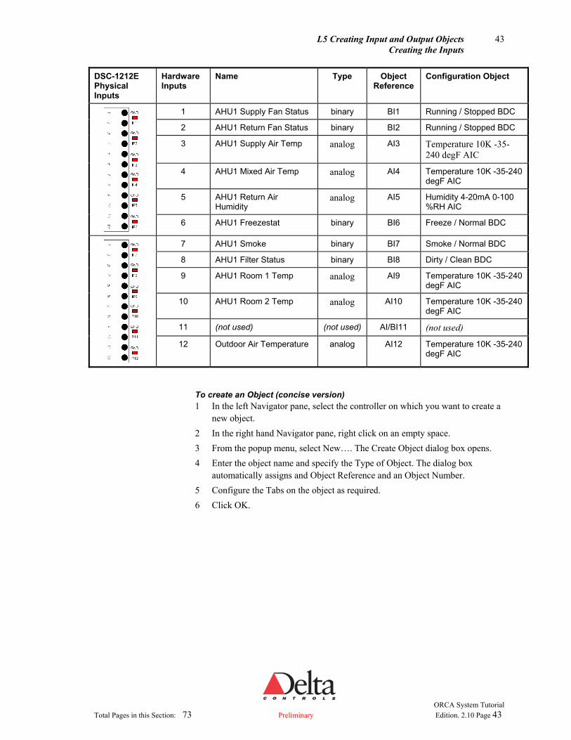
L5 Creating Input and Output Objects Creating the Inputs
ORCA System Tutorial
Total Pages in this Section: 73 Preliminary Edition. 2.10 Page 43
43
DSC-1212E Physical Inputs
Hardware Inputs
Name Type Object Reference
Configuration Object
1 AHU1 Supply Fan Status binary BI1 Running / Stopped BDC
2 AHU1 Return Fan Status binary BI2 Running / Stopped BDC
3 AHU1 Supply Air Temp analog AI3 Temperature 10K -35-240 degF AIC
4 AHU1 Mixed Air Temp analog AI4 Temperature 10K -35-240 degF AIC
5 AHU1 Return Air Humidity
analog AI5 Humidity 4-20mA 0-100 %RH AIC
6 AHU1 Freezestat binary BI6 Freeze / Normal BDC
7 AHU1 Smoke binary BI7 Smoke / Normal BDC
8 AHU1 Filter Status binary BI8 Dirty / Clean BDC
9 AHU1 Room 1 Temp analog AI9 Temperature 10K -35-240 degF AIC
10 AHU1 Room 2 Temp analog AI10 Temperature 10K -35-240 degF AIC
11 (not used) (not used) AI/BI11 (not used)
12 Outdoor Air Temperature analog AI12 Temperature 10K -35-240 degF AIC
To create an Object (concise version) 1 In the left Navigator pane, select the controller on which you want to create a
new object. 2 In the right hand Navigator pane, right click on an empty space. 3 From the popup menu, select New…. The Create Object dialog box opens. 4 Enter the object name and specify the Type of Object. The dialog box
automatically assigns and Object Reference and an Object Number. 5 Configure the Tabs on the object as required. 6 Click OK.
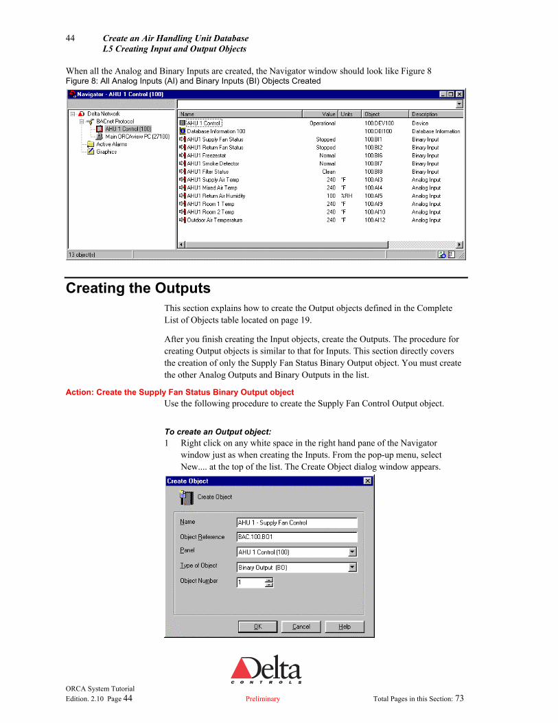
Create an Air Handling Unit Database L5 Creating Input and Output Objects
ORCA System Tutorial Edition. 2.10 Page 44 Preliminary Total Pages in this Section: 73
44
When all the Analog and Binary Inputs are created, the Navigator window should look like Figure 8 Figure 8: All Analog Inputs (AI) and Binary Inputs (BI) Objects Created
Creating the Outputs This section explains how to create the Output objects defined in the Complete List of Objects table located on page 19.
After you finish creating the Input objects, create the Outputs. The procedure for creating Output objects is similar to that for Inputs. This section directly covers the creation of only the Supply Fan Status Binary Output object. You must create the other Analog Outputs and Binary Outputs in the list.
Action: Create the Supply Fan Status Binary Output object Use the following procedure to create the Supply Fan Control Output object.
To create an Output object: 1 Right click on any white space in the right hand pane of the Navigator
window just as when creating the Inputs. From the pop-up menu, select New.... at the top of the list. The Create Object dialog window appears.

L5 Creating Input and Output Objects Creating the Outputs
ORCA System Tutorial
Total Pages in this Section: 73 Preliminary Edition. 2.10 Page 45
45
2 Click on the Type of Object drop-down list and slide down the list until you reach Binary Output (BO). Select the Binary Output (BO) and then the remaining information can be entered in the Create Object dialog window.
3 Type the Object Number. For this example, select Object Number 1. The Object Number corresponds to the physical hardware output number and is restricted to 1-12 for a DSC-1212 controller.
4 Type the object name in the Name field and click OK. For the tutorial example, type the name AHU1 Supply Fan Control. The Object dialog window appears for the newly created Output. Figure 9 shows the Setup tab.
5 Next, select the Device tab. You configure the Output here. 6 Select the desired Device Type setting. For the tutorial example, select Run /
Stop BDC as shown in Figure 10: Device Tab of Supply Fan Control Binary Outputs (BO1).
7 Click OK. Figure 9: Setup Tab of Supply Fan Control Binary Outputs (BO1)

Create an Air Handling Unit Database L5 Creating Input and Output Objects
ORCA System Tutorial Edition. 2.10 Page 46 Preliminary Total Pages in this Section: 73
46
Figure 10: Device Tab of Supply Fan Control Binary Outputs (BO1)
A Computer icon may display in the upper right area of the header in an Output object. The icon shows that the HOA switch for this output is in the Auto position. Navigator also displays HOA icons in the OFF and Hand columns for objects in the Details view.

L5 Creating Input and Output Objects Creating the Outputs
ORCA System Tutorial
Total Pages in this Section: 73 Preliminary Edition. 2.10 Page 47
47
Action: Create the 6 remaining Output objects You must create all the remaining Outputs for the tutorial. Be careful to select the correct Object Number. It is better if you create the remaining inputs in the order given in the following table as the automatically assigned Object Reference and Object Numbers will tend to be as required.
DSC-1212E Physical Outputs
Hardware Outputs
Name Type Object Reference
Configuration Object
1 AHU1 Supply Fan Control binary BO1 Run / Stop BDC (BDC7)
2 AHU1 Return Fan Control binary BO2 Run / Stop BDC
3 AHU1 Mixed Air Damper Control
analog AO3 Belimo 2-10 VDC Output AOC (AOC1)
4 AHU1 Heating Coil Valve Control
analog AO4 Belimo 2-10 VDC Output AOC
5 AHU1 Heating Pump Control
binary BO5 Run / Stop BDC
6 AHU1 Cooling Coil Valve Control
analog AO6 Belimo 2-10 VDC Output AOC
7 AHU1 Humidity Valve Control
analog AO7 Belimo 2-10 VDC Output AOC
8 (not used)
9 (not used)
10 (not used)
11 (not used)
12 (not used)
To create an Object (concise version) 1 In the left Navigator pane, select the controller on which you want to create a
new object. 2 In the right hand Navigator pane, right click on an empty space. 3 From the popup menu, select New…. The Create Object dialog box opens. 4 Enter the object name and specify the Type of Object. The dialog box
automatically assigns and Object Reference and an Object Number. 5 Configure the Tabs on the object as required. 6 Click OK.

Create an Air Handling Unit Database L5 Creating Input and Output Objects
ORCA System Tutorial Edition. 2.10 Page 48 Preliminary Total Pages in this Section: 73
48
Moving On You have completed this lesson. For information on additional features of Navigator, see Chapter 10 Software Object Reference PDF file of the Technical Reference manual. Additionally, you can press the F1 Key on a field or the Navigator window and get specific help. Each software object has a ? Help button on the dialog in the lower right corner.
L6 Creating Setpoints, Variables and Control Loops Creating the Outputs
ORCA System Tutorial
Total Pages in this Section: 73 Preliminary Edition. 2.10 Page 49
49
Lesson 6 – L6 CREATING SETPOINTS, VARIABLES AND CONTROL LOOPS
This lesson explains the basics of the creating objects such as Analog Variables Multi-State Variables, and Control Loops.
Variables may be Analog Variables, Binary Variables, or Multi-State Variables. Binary Variable objects store ON/OFF states while Analog Variables store numbers. Multi-State Variables (MV’s) store multiple states.
For example, a programmer may wish to store a user-adjustable room temperature setpoint as an Analog Variable. This Analog Variable would hold the current analog setpoint value that a program uses to control the temperature of the room.
In this lesson, you will learn how to do the following: Create Analog Variables. Create Multi-State Variables. Create Control loops.
Create Analog and Binary Variables After you finish creating the Output objects, create any Analog Variable (AV) and Binary Variable (BV) objects. This tutorial covers the creation of only one Analog Variable object for the Supply Air Temperature Setpoint. You must create the other setpoints from the Analog Variables in the list. The tutorial does not have any Binary Variables.
The procedure for creating Analog and Binary Variable objects is similar to that for Input and Output objects.
Action: Create the Supply Air Temperature Setpoint Analog Variable object Use the following procedure to create the Supply Air Temperature Setpoint Analog Variable object.

Create an Air Handling Unit Database L6 Creating Setpoints, Variables and Control Loops
ORCA System Tutorial Edition. 2.10 Page 50 Preliminary Total Pages in this Section: 73
50
To create an Analog Variable object: 1 Right click on any white space in the right hand pane of the Navigator
window. From the pop-up menu, select New.... at the top of the list. The Create Object dialog window appears.
2 In the Create Object dialog box, select Analog Variable (AV) from the Type of Object drop-down list.
3 Type the correct Object Number. The Object Number field automatically updates to the next available Analog Variable number. For the tutorial AHU1 Supply Air Temp Setpoint Analog Variable example, set the number to 1.
4 Type the name in the Name field and click OK. For the tutorial example, type AHU1 Supply Air Temp Setpoint.
5 After the creation of the Analog Variable object, the Object dialog window appears.
6 Click on the Setup tab. 7 Select the correct Units from the drop-down list. For the Supply Air setpoint
Analog Variable tutorial example, select ºF. Figure 11: Setup tab of Supply Air Temp Setpoint Analog Variable shows the Analog Variable object correctly configured.
8 Click OK. Figure 11: Setup tab of Supply Air Temp Setpoint Analog Variable
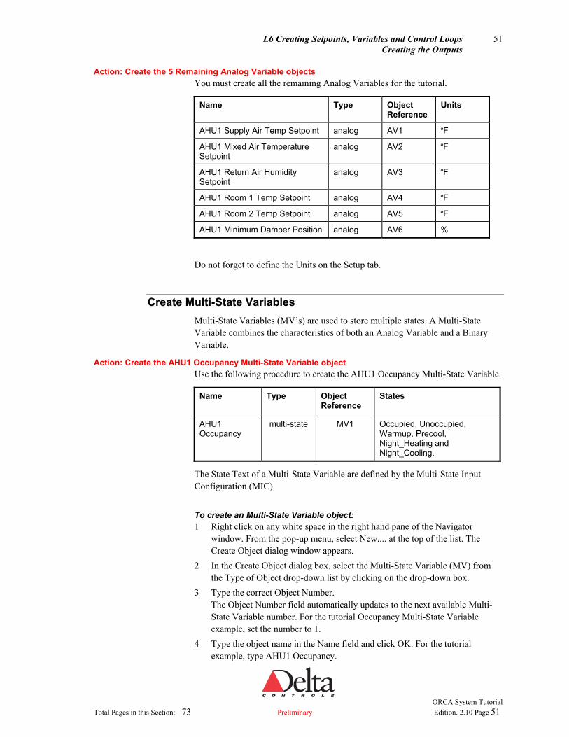
L6 Creating Setpoints, Variables and Control Loops Creating the Outputs
ORCA System Tutorial
Total Pages in this Section: 73 Preliminary Edition. 2.10 Page 51
51
Action: Create the 5 Remaining Analog Variable objects You must create all the remaining Analog Variables for the tutorial.
Name Type Object Reference
Units
AHU1 Supply Air Temp Setpoint analog AV1 ºF
AHU1 Mixed Air Temperature Setpoint
analog AV2 ºF
AHU1 Return Air Humidity Setpoint
analog AV3 ºF
AHU1 Room 1 Temp Setpoint analog AV4 ºF
AHU1 Room 2 Temp Setpoint analog AV5 ºF
AHU1 Minimum Damper Position analog AV6 %
Do not forget to define the Units on the Setup tab.
Create Multi-State Variables Multi-State Variables (MV’s) are used to store multiple states. A Multi-State Variable combines the characteristics of both an Analog Variable and a Binary Variable.
Action: Create the AHU1 Occupancy Multi-State Variable object Use the following procedure to create the AHU1 Occupancy Multi-State Variable.
Name Type Object Reference
States
AHU1 Occupancy
multi-state MV1 Occupied, Unoccupied, Warmup, Precool, Night_Heating and Night_Cooling.
The State Text of a Multi-State Variable are defined by the Multi-State Input Configuration (MIC).
To create an Multi-State Variable object: 1 Right click on any white space in the right hand pane of the Navigator
window. From the pop-up menu, select New.... at the top of the list. The Create Object dialog window appears.
2 In the Create Object dialog box, select the Multi-State Variable (MV) from the Type of Object drop-down list by clicking on the drop-down box.
3 Type the correct Object Number. The Object Number field automatically updates to the next available Multi-State Variable number. For the tutorial Occupancy Multi-State Variable example, set the number to 1.
4 Type the object name in the Name field and click OK. For the tutorial example, type AHU1 Occupancy.
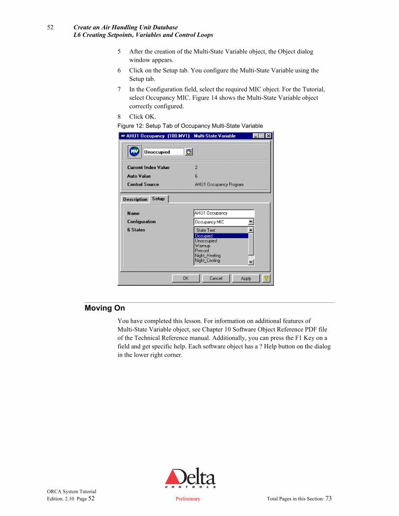
Create an Air Handling Unit Database L6 Creating Setpoints, Variables and Control Loops
ORCA System Tutorial Edition. 2.10 Page 52 Preliminary Total Pages in this Section: 73
52
5 After the creation of the Multi-State Variable object, the Object dialog window appears.
6 Click on the Setup tab. You configure the Multi-State Variable using the Setup tab.
7 In the Configuration field, select the required MIC object. For the Tutorial, select Occupancy MIC. Figure 14 shows the Multi-State Variable object correctly configured.
8 Click OK. Figure 12: Setup Tab of Occupancy Multi-State Variable
Moving On You have completed this lesson. For information on additional features of Multi-State Variable object, see Chapter 10 Software Object Reference PDF file of the Technical Reference manual. Additionally, you can press the F1 Key on a field and get specific help. Each software object has a ? Help button on the dialog in the lower right corner.
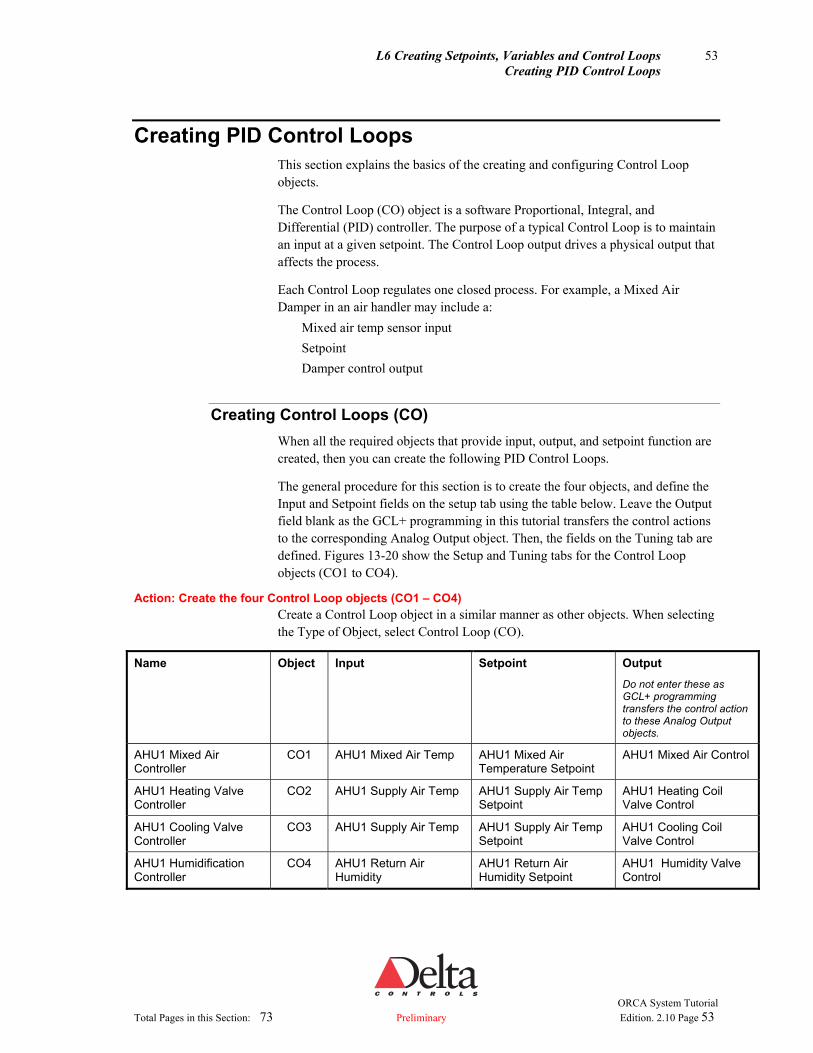
L6 Creating Setpoints, Variables and Control Loops Creating PID Control Loops
ORCA System Tutorial
Total Pages in this Section: 73 Preliminary Edition. 2.10 Page 53
53
Creating PID Control Loops This section explains the basics of the creating and configuring Control Loop objects.
The Control Loop (CO) object is a software Proportional, Integral, and Differential (PID) controller. The purpose of a typical Control Loop is to maintain an input at a given setpoint. The Control Loop output drives a physical output that affects the process.
Each Control Loop regulates one closed process. For example, a Mixed Air Damper in an air handler may include a: Mixed air temp sensor input Setpoint Damper control output
Creating Control Loops (CO) When all the required objects that provide input, output, and setpoint function are created, then you can create the following PID Control Loops.
The general procedure for this section is to create the four objects, and define the Input and Setpoint fields on the setup tab using the table below. Leave the Output field blank as the GCL+ programming in this tutorial transfers the control actions to the corresponding Analog Output object. Then, the fields on the Tuning tab are defined. Figures 13-20 show the Setup and Tuning tabs for the Control Loop objects (CO1 to CO4).
Action: Create the four Control Loop objects (CO1 – CO4) Create a Control Loop object in a similar manner as other objects. When selecting the Type of Object, select Control Loop (CO).
Name Object Input Setpoint Output Do not enter these as GCL+ programming transfers the control action to these Analog Output objects.
AHU1 Mixed Air Controller
CO1 AHU1 Mixed Air Temp AHU1 Mixed Air Temperature Setpoint
AHU1 Mixed Air Control
AHU1 Heating Valve Controller
CO2 AHU1 Supply Air Temp AHU1 Supply Air Temp Setpoint
AHU1 Heating Coil Valve Control
AHU1 Cooling Valve Controller
CO3 AHU1 Supply Air Temp AHU1 Supply Air Temp Setpoint
AHU1 Cooling Coil Valve Control
AHU1 Humidification Controller
CO4 AHU1 Return Air Humidity
AHU1 Return Air Humidity Setpoint
AHU1 Humidity Valve Control
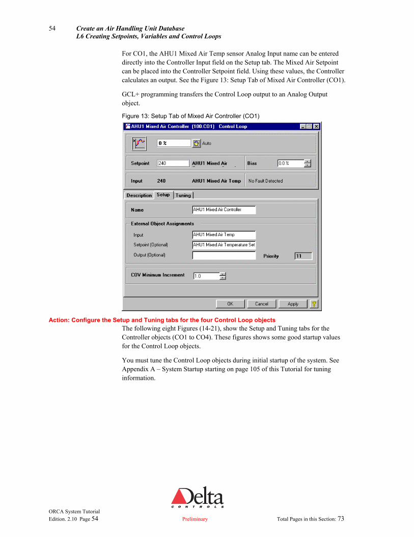
Create an Air Handling Unit Database L6 Creating Setpoints, Variables and Control Loops
ORCA System Tutorial Edition. 2.10 Page 54 Preliminary Total Pages in this Section: 73
54
For CO1, the AHU1 Mixed Air Temp sensor Analog Input name can be entered directly into the Controller Input field on the Setup tab. The Mixed Air Setpoint can be placed into the Controller Setpoint field. Using these values, the Controller calculates an output. See the Figure 13: Setup Tab of Mixed Air Controller (CO1).
GCL+ programming transfers the Control Loop output to an Analog Output object.
Figure 13: Setup Tab of Mixed Air Controller (CO1)
Action: Configure the Setup and Tuning tabs for the four Control Loop objects
The following eight Figures (14-21), show the Setup and Tuning tabs for the Controller objects (CO1 to CO4). These figures shows some good startup values for the Control Loop objects.
You must tune the Control Loop objects during initial startup of the system. See Appendix A – System Startup starting on page 105 of this Tutorial for tuning information.
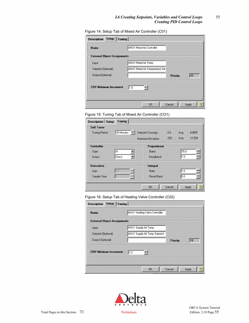
L6 Creating Setpoints, Variables and Control Loops Creating PID Control Loops
ORCA System Tutorial
Total Pages in this Section: 73 Preliminary Edition. 2.10 Page 55
55
Figure 14: Setup Tab of Mixed Air Controller (C01)
Figure 15: Tuning Tab of Mixed Air Controller (CO1)
Figure 16: Setup Tab of Heating Valve Controller (C02)
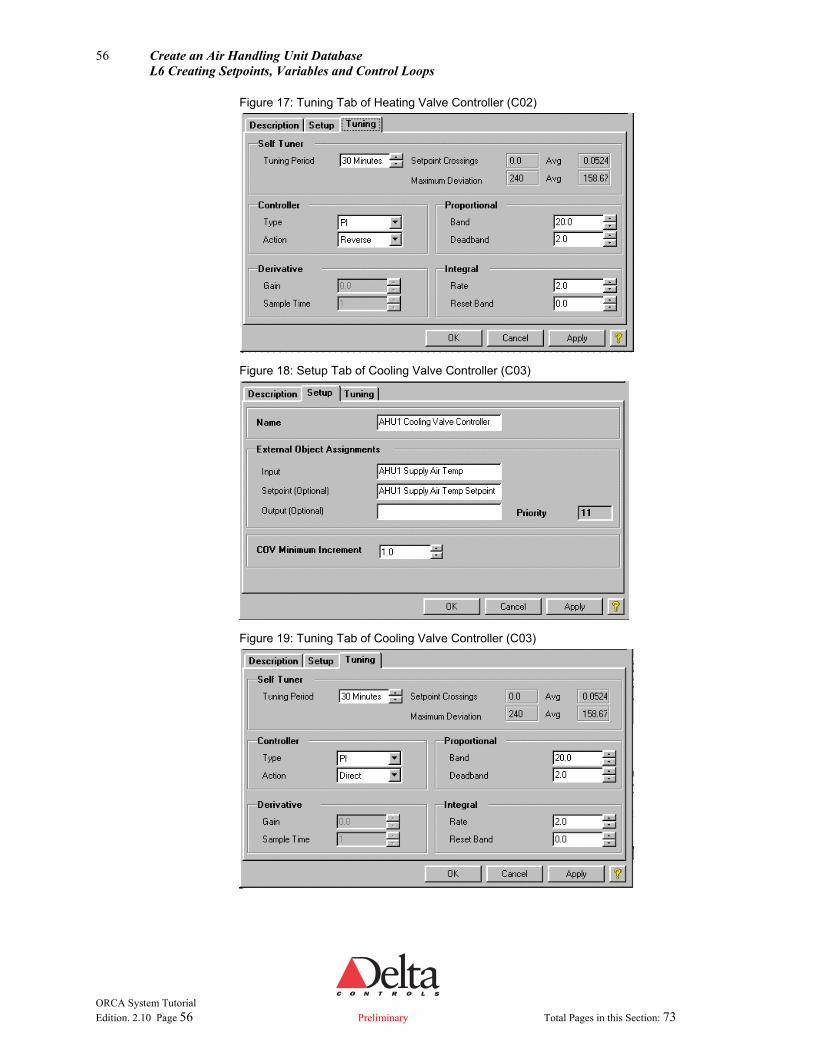
Create an Air Handling Unit Database L6 Creating Setpoints, Variables and Control Loops
ORCA System Tutorial Edition. 2.10 Page 56 Preliminary Total Pages in this Section: 73
56
Figure 17: Tuning Tab of Heating Valve Controller (C02)
Figure 18: Setup Tab of Cooling Valve Controller (C03)
Figure 19: Tuning Tab of Cooling Valve Controller (C03)

L6 Creating Setpoints, Variables and Control Loops Creating PID Control Loops
ORCA System Tutorial
Total Pages in this Section: 73 Preliminary Edition. 2.10 Page 57
57
Figure 20: Setup Tab of Humidification Controller (CO4)
Figure 21: Tuning Tab of Humidification Controller (CO4)
Moving On You have completed this lesson. For information on additional features of the Analog Variable, Binary Variable, Multi-State, or Control Loop objects, see Chapter 10 Software Object Reference PDF file of the Technical Reference manual. Additionally, you can press the F1 Key on a field and get specific help. Each software object also has a ? Help button on the dialog in the lower right corner.
Appendix A of this tutorial contains information on how to tune the Control Loops during initial startup.

Create an Air Handling Unit Database L7 Creating Schedules, Calendars and Optimum Starts
ORCA System Tutorial Edition. 2.10 Page 58 Preliminary Total Pages in this Section: 73
58
Lesson 7 – L7 CREATING SCHEDULES, CALENDARS AND OPTIMUM STARTS
This lesson explains the basics of the creating and configuring Schedules, Calendars and Optimum Start objects.
The Schedule (SCH) object stores the start and stop times for a system. A Schedule defines the weekly operation of a system.
The Calendar (CAL) object stores holidays or special days. Typically, marked dates within a Calendar override the normal start and stop times in a Schedule. The equipment follows a different schedule or is off entirely for the marked days on the Calendar. Typically, only one or two Calendars are required for a building.
The Optimum Start object ensures that a space is at a desired temperature prior to scheduled occupancy.
In this lesson, you will learn how to do the following: Create Schedule object. Create Calendar object. Create Optimum Start object.
Create Schedules The AHU1 Weekly Schedule is the only Schedule object required for the system. You type the start and stop times from the Sequence of Operations into the Schedule object.
Action: Create the Schedule object (SCH1) You can create a Schedule object in a similar manner to other objects.
Name Type Object Reference
Description
AHU1 Weekly Schedule
Schedule SCH1 Air Handling Unit 1
Use the following procedure to create the AHU1 Weekly Schedule object.

L7 Creating Schedules, Calendars and Optimum Starts Creating PID Control Loops
ORCA System Tutorial
Total Pages in this Section: 73 Preliminary Edition. 2.10 Page 59
59
To create a Schedule object: 1 Right click on any white space in the right hand pane of the Navigator
window. From the pop-up menu, select New.... at the top of the list. The Create Object dialog window appears.
2 In the Create Object dialog box, select Schedule (SCH) from the Type of Object drop-down list.
3 Type the correct Object Number. The Object Number field automatically updates to the next available Schedule number. For the tutorial Schedule example, set the number to 1.
4 Type the name in the Name field and select OK. For the tutorial Schedule example, type AHU1 Weekly Schedule.
5 After the creation of the Weekly Schedule object, the Object dialog window appears. For the tutorial Weekly Schedule example, the new name at the top of this window is AHU1 Weekly Schedule.
6 Create the run times by clicking at the start point and then dragging the mouse to the stop time for each day of the week. Double clicking on the run bar allows you to do fine adjustment of the running time that has been created for each day. The following Figure 22 shows the Weekly Schedule Main tab for this location.
7 Click OK. Figure 22: Main Tab of AHU1 Weekly Schedule (SCH1)

Create an Air Handling Unit Database L7 Creating Schedules, Calendars and Optimum Starts
ORCA System Tutorial Edition. 2.10 Page 60 Preliminary Total Pages in this Section: 73
60
Create Calendars The system requires only the Holiday Calendar. During the Holiday Calendar days, the system is idle.
Action: Create the Calendar object (CAL1) You can create a Calendar object in a similar manner to other objects.
Name Type Object Reference
Description
Holiday Calendar Calendar CAL1 Site holidays
Use the following procedure to create the Holiday Calendar object.
To create a Calendar object: 1 Right click on any white space in the right hand pane of the Navigator
window. From the pop-up menu, select New.... at the top of the list. The Create Object dialog window appears.
2 In the Create Object dialog box, select Calendar (CAL) from the Type of Object drop-down list.
3 Type the correct Object Number. The Object Number field automatically updates to the next available Calendar number. For the tutorial Calendar example, set the number to 1.
4 Type the name in the Name field and select OK. For the tutorial Calendar example, type Holiday Calendar.
5 After the creation of the Calendar object, the Object dialog window displays. For the tutorial Calendar example, the new name at the top of this window is Holiday Calendar.
6 When the Object dialog window appears, the current month and year as determined by your PC clock appears.
7 Enter the special event days by clicking on the appropriate days. The sequence of operations does not specify any special event days as they are usually coordinated with the occupants. Consecutive clicks on the same day will select and deselect it. Select a few random days for practice. The month is selected by clicking on the arrow keys beside the month.
8 Click OK. The following Figure 23 shows the Calendar set up for July for this location.
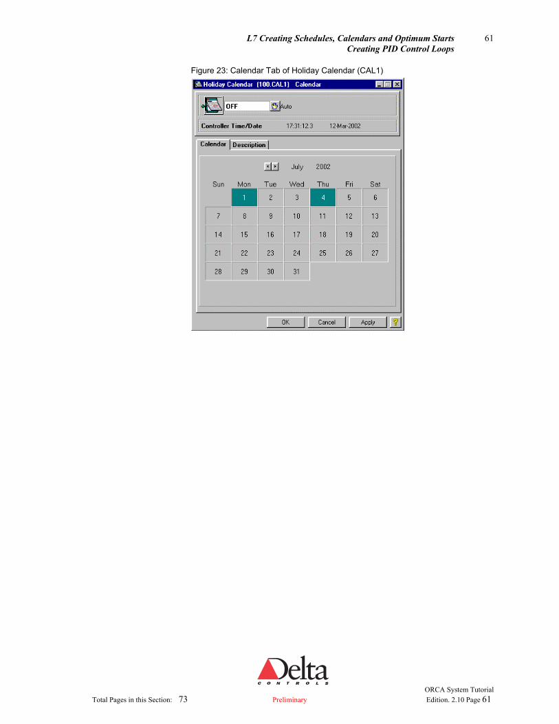
L7 Creating Schedules, Calendars and Optimum Starts Creating PID Control Loops
ORCA System Tutorial
Total Pages in this Section: 73 Preliminary Edition. 2.10 Page 61
61
Figure 23: Calendar Tab of Holiday Calendar (CAL1)

Create an Air Handling Unit Database L7 Creating Schedules, Calendars and Optimum Starts
ORCA System Tutorial Edition. 2.10 Page 62 Preliminary Total Pages in this Section: 73
62
Create Optimum Start The Optimum Start object starts equipment before its Schedule object comes on, so that the space can be brought to the desired temperature prior to occupancy.
The Optimum Start Object (OS) is a programmable object that: Calculates the warm-up or cool-down time, based on both past performance
and changes in the Outdoor Air Temperature. Determines the optimum time to start heating and cooling equipment. Typically, an OS object is used for a fan system that does not run over night. The OS automatically determines the best time to start the equipment in the morning in order to achieve the desired temperature when the scheduled occupancy begins.
When deciding what time to bring on the equipment, the OS may use a number of factors: History over the past three days Outdoor temperature Scheduled occupied time Actual space temperature while unoccupied Desired target space temperature Extended unoccupied time (weekends or holidays).
Action: Create the two Optimum Start objects (OS1-OS2) The system requires two Optimum Start objects, one for heating and the other for cooling. Figures 24 and 25 shows the Optimum Start Setup tab for OS1 and OS2 respectively. You need to enter these parameters when you create the objects.
Name Type Object Reference
Description
AHU1 Heating Optimum Start Heating OS1 Start of Supply and return fans. Heating start.
AHU1 Cooling Optimum Start Cooling OS2 Start of Supply and return fans. Cooling start.
Use the following procedure to create both the Optimum Start objects.

L7 Creating Schedules, Calendars and Optimum Starts Creating PID Control Loops
ORCA System Tutorial
Total Pages in this Section: 73 Preliminary Edition. 2.10 Page 63
63
To create an Optimum Start object: 1 Right click on any white space in the right hand pane of the Navigator
window. From the pop-up menu, select New.... at the top of the list. The Create Object dialog window appears.
2 In the Create Object dialog box, select Optimum Start (OS) from the Type of Object drop-down list.
3 Type the correct Object Number. The Object Number field automatically updates to the next available Optimum Start (OS) number. For the tutorial Optimum Start (OS) example, there are 2 Optimum Start objects to create.
4 Type the name in the Name field and select OK. For the tutorial example, type AHU1 Heating Optimum Start for the first object.
5 After the creation of the Optimum Start object, the Object dialog window appears.
6 Click on the Setup tab. You configure the Optimum Start using the Setup tab. 7 Select the Start Type in the drop-down. Select Heating Start for OS1. 8 Enter the Analog Input name into the Indoor Temperature field. For the
tutorial Optimum Start (OS1) example, the object is AHU1 Room 1 Temp or AI9.
9 Type in the Schedule Object name in the Schedule Object field. You can also drag and drop an object from the Navigator Window to this Monitored Object field.
10 Type in the name of the Analog Input for the Outdoor Temperature in the Optional Parameters. You can also drag and drop an object from the Navigator Window. Figures 24 and 25 shows the fields on the Optimum Start Setup tab for OS1 and OS2 respectively.
11 Click OK.

Create an Air Handling Unit Database L7 Creating Schedules, Calendars and Optimum Starts
ORCA System Tutorial Edition. 2.10 Page 64 Preliminary Total Pages in this Section: 73
64
Figure 24: Setup Tab of Heating Optimum Start (OS1)
You create the AHU1 Cooling Optimum Start (100.OS2) in a similar manner.
Figure 25: Setup Tab of Cooling Optimum Start (OS2)

L7 Creating Schedules, Calendars and Optimum Starts Creating PID Control Loops
ORCA System Tutorial
Total Pages in this Section: 73 Preliminary Edition. 2.10 Page 65
65
Moving On You have completed this lesson. For information on additional features of Schedules, Calendars and Optimum Start objects, see Chapter 10 Software Object Reference PDF file of the Technical Reference manual. Additionally, you can press the F1 Key on a field and get specific help. Each software object has a ? Help button on the dialog in the lower right corner.
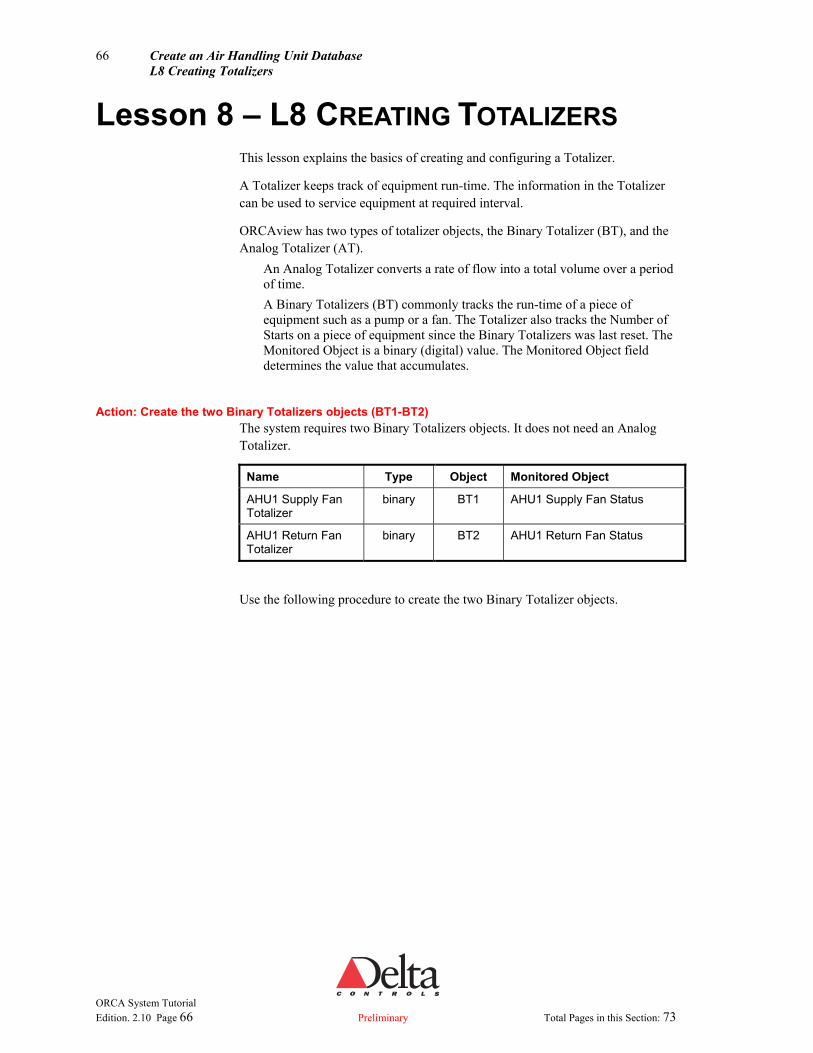
Create an Air Handling Unit Database L8 Creating Totalizers
ORCA System Tutorial Edition. 2.10 Page 66 Preliminary Total Pages in this Section: 73
66
Lesson 8 – L8 CREATING TOTALIZERS This lesson explains the basics of creating and configuring a Totalizer.
A Totalizer keeps track of equipment run-time. The information in the Totalizer can be used to service equipment at required interval.
ORCAview has two types of totalizer objects, the Binary Totalizer (BT), and the Analog Totalizer (AT). An Analog Totalizer converts a rate of flow into a total volume over a period
of time. A Binary Totalizers (BT) commonly tracks the run-time of a piece of
equipment such as a pump or a fan. The Totalizer also tracks the Number of Starts on a piece of equipment since the Binary Totalizers was last reset. The Monitored Object is a binary (digital) value. The Monitored Object field determines the value that accumulates.
Action: Create the two Binary Totalizers objects (BT1-BT2) The system requires two Binary Totalizers objects. It does not need an Analog Totalizer.
Name Type Object Monitored Object
AHU1 Supply Fan Totalizer
binary BT1 AHU1 Supply Fan Status
AHU1 Return Fan Totalizer
binary BT2 AHU1 Return Fan Status
Use the following procedure to create the two Binary Totalizer objects.
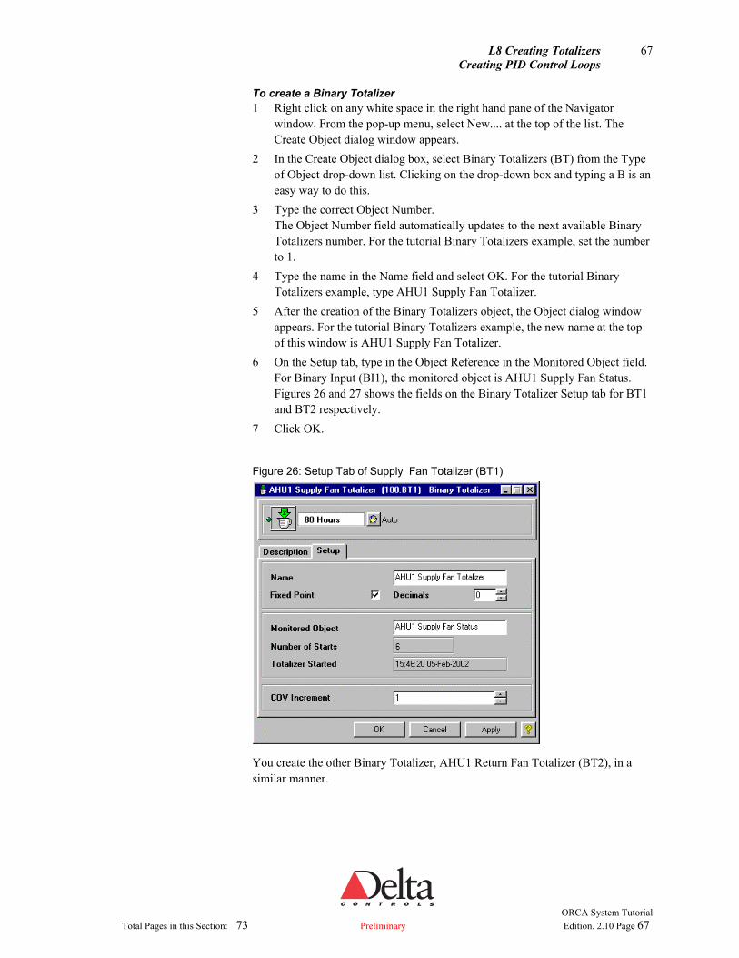
L8 Creating Totalizers Creating PID Control Loops
ORCA System Tutorial
Total Pages in this Section: 73 Preliminary Edition. 2.10 Page 67
67
To create a Binary Totalizer 1 Right click on any white space in the right hand pane of the Navigator
window. From the pop-up menu, select New.... at the top of the list. The Create Object dialog window appears.
2 In the Create Object dialog box, select Binary Totalizers (BT) from the Type of Object drop-down list. Clicking on the drop-down box and typing a B is an easy way to do this.
3 Type the correct Object Number. The Object Number field automatically updates to the next available Binary Totalizers number. For the tutorial Binary Totalizers example, set the number to 1.
4 Type the name in the Name field and select OK. For the tutorial Binary Totalizers example, type AHU1 Supply Fan Totalizer.
5 After the creation of the Binary Totalizers object, the Object dialog window appears. For the tutorial Binary Totalizers example, the new name at the top of this window is AHU1 Supply Fan Totalizer.
6 On the Setup tab, type in the Object Reference in the Monitored Object field. For Binary Input (BI1), the monitored object is AHU1 Supply Fan Status. Figures 26 and 27 shows the fields on the Binary Totalizer Setup tab for BT1 and BT2 respectively.
7 Click OK.
Figure 26: Setup Tab of Supply Fan Totalizer (BT1)
You create the other Binary Totalizer, AHU1 Return Fan Totalizer (BT2), in a similar manner.

Create an Air Handling Unit Database L8 Creating Totalizers
ORCA System Tutorial Edition. 2.10 Page 68 Preliminary Total Pages in this Section: 73
68
Figure 27: Setup Tab of Return Fan Totalizer (BT2)
Moving On You have completed this lesson. For information on additional features of Analog and Binary Totalizer objects, see Chapter 10 Software Object Reference PDF file of the Technical Reference manual. Additionally, you can press the F1 Key on a field and get specific help. Each software object has a ? Help button on the dialog in the lower right corner.

L9 Creating GCL+ Programs Introduction
ORCA System Tutorial
Total Pages in this Section: 73 Preliminary Edition. 2.10 Page 69
69
Lesson 9 – L9 CREATING GCL+ PROGRAMS
The lesson explains the basics of the GCL+ programming environment and describes recommended practices for program development. Now that we have created most of the objects for the system, we are ready to address the system programming. You will create the programs by inputting existing code and do not have to write the code yourself. The tutorial does not explains the details of the GCL+ Programming Language.
In this lesson, you will learn how to do the following: Use the basic functions of the Program Editor. Describe commenting and formatting guidelines. Call programs from the PG1 Master Program.
Introduction General Control Language (GCL+) is a powerful programming language that is the backbone of the products from Delta Controls. Much of the control functionality is done using GCL+ including sequences, calculations, linking of objects as well as an assortment of other minor tasks.
To learn more about GCL+, you can: Press F1 to get help about a specific area. Within the GCL+ code itself, you
can select a program construct such as CALL and press F1 to get information about the CALL function.
Press the Help button on the Program object. See the Chapter 11 GCL+ Programming Reference of the ORCAview
Technical Reference manual available as a PDF file on the ORCAview Release CD-ROM.
Writing GCL+ Programs to Control the System You need to learn to program in GCL+. Along with the power of GCL+ comes some complexity. By following basic guidelines and conventions, you can learn to write effective programs very quickly. You can also make it possible for others to easily interpret and troubleshoot the same programming.
The Programs in this section show proper programming practice and are a good guide for creating your own Programs.
Programs The Program (PG) object performs linking, most computations, and sequencing for the purpose of control. Programming inside the Program object performs the linking between different software objects. The programming controls all the control devices and sequences them properly. For example, a series of Program objects may contain all the programming required to control an air handling unit.
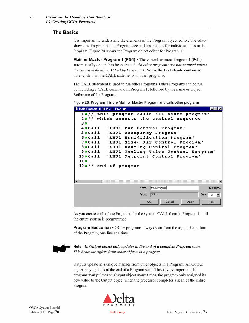
Create an Air Handling Unit Database L9 Creating GCL+ Programs
ORCA System Tutorial Edition. 2.10 Page 70 Preliminary Total Pages in this Section: 73
70
The Basics It is important to understand the elements of the Program object editor. The editor shows the Program name, Program size and error codes for individual lines in the Program. Figure 28 shows the Program object editor for Program 1.
Main or Master Program 1 (PG1) The controller scans Program 1 (PG1) automatically once it has been created. All other programs are not scanned unless they are specifically CALLed by Program 1. Normally, PG1 should contain no other code than the CALL statements to other programs.
The CALL statement is used to run other Programs. Other Programs can be run by including a CALL command in Program 1, followed by the name or Object Reference of the Program.
Figure 28: Program 1 is the Main or Master Program and calls other programs
As you create each of the Programs for the system, CALL them in Program 1 until the entire system is programmed.
Program Execution GCL+ programs always scan from the top to the bottom of the Program, one line at a time.
Note: An Output object only updates at the end of a complete Program scan. This behavior differs from other objects in a program.
Outputs update in a unique manner from other objects in a Program. An Output object only updates at the end of a Program scan. This is very important! If a program manipulates an Output object many times, the program only assigned its new value to the Output object when the processor completes a scan of the entire Program.
L9 Creating GCL+ Programs Writing GCL+ Programs to Control the System
ORCA System Tutorial
Total Pages in this Section: 73 Preliminary Edition. 2.10 Page 71
71
For example, if the Mixed Air Dampers are closed (0%) when the program begins, the Cooling Coil Valve will not close at the end of this scan. The Mixed Air Damper Output still has a value of 0%, until the whole program executes.
Mixed Air DamperControl = 10 If Mixed Mixed Air Damper Control = 10 Then Cooling Coil Valve control = 0 EndIF For this reason, any safety functions required in a system should be written at the end of the Program.
Guidelines for Creating Programs This section provides some guidelines for proper programming practice.
Maximum Size Here are some important size limits to consider: The GCL+ editor accepts a line of up to 255 characters in width. This
includes all characters including spaces and comments. A single program cannot exceed a maximum of 5.5k bytes (DAC/ DSC) or
24k bytes (DCU) or 999 lines whichever comes first. The recommended maximum size of a single program is approximately 4k
bytes. If you exceed this maximum size, the program becomes long and hard to read.
Formatting a Program Proper indentation, spacing and comments are very important when writing GCL+ programs.
Reading and troubleshooting programs is easier with proper indenting. Delta Controls recommends indenting two spaces after every loop statement. For example, the lines following an IF condition, in an IF-THEN-ELSE-ENDIF statement, should be indented two spaces from the margin of the IF condition.
If ‘AHU1 OCCUPIED’ Then Start ‘AHU1 Return Fan Control’ If ‘AHU1 Return Fan Status’ OnFor 10s Then Start ‘AHU1 Supply Fan Control’ End If Else Stop ‘AHU1 Return Fan Control’ End If Proper spacing includes proper vertical spacing. Blank lines are used to separate the different logical segments of a program and create a more pleasing and easy to read format.
Commenting a Program Commenting your code in a conscientious manner may be the single most important task in programming GCL+. Comments allows yourself and others to quickly understand any Program, even if written in the distant past. If a program is commented properly it is easy to find where a particular task is performed.

Create an Air Handling Unit Database L9 Creating GCL+ Programs
ORCA System Tutorial Edition. 2.10 Page 72 Preliminary Total Pages in this Section: 73
72
The amount of detail in the Program comments depends on how much memory is available and how knowledgeable the user is.
Some general rules for comments follow: Comment each code segment within a program. Comments are inserted by putting // at the beginning of the comment line. Comments should always be indented the same as the statement they refer to. If more than one line is used to comment a portion of programming, both
comment lines should be the same length, whether or not the same amount of space is used on the second line. This shows at a glance that the two lines belong to each other.
It is recommended to state the intent of the program in the comments and not just what each line does. This approach helps others to troubleshoot your programs.
Modular Programming Every system can be broken up into a series of modules. For example, an Air Handling Unit can be broken down into Return Fan, Supply Fan, Mixed Air Dampers, Heating, Cooling, Humidity, etc.
Modular programming can be done in two ways: 1 Make separate programs for every component of the equipment. This is the
recommended approach. 2 Combine the programming modules within a single program to control an
entire piece of equipment such as an Air Handling Unit. There are advantages and disadvantages to each method. In the first method, there are more programs to look through but the programs are much shorter. This makes it easier to track down a problem within a particular code segment. Also, it is easier to reuse code with short programs. In the second method, the Programs tend to be a lot longer but all of the code is contained in a single Program.
Flow of Programming A program should flow in a logical order from the top down and from the first Program to the last. When controlling an Air Handling Unit, the fans should be started first, before attempting to control the mixed air dampers. Therefore, the starting of the fan should come first in the program.
Long Names with Spaces In GCL+ code, when you use long names or object names with spaces, they must have an apostrophe ‘mark at the beginning and end of the name. For example, the name for BI2 is enclosed within apostrophe ‘ marks
Start ‘AHU1 Return Fan Status’ Remember that object names are case-sensitive.
Program for Fan Control The following Figure 29 Fan Control Program (PG2) shows how an Occupancy Multi-State Variable is linked to control a Supply and Return Fan through GCL+ programming. Much programming that is done utilizes the IF-THEN-ELSE-ENDIF conditional statement. The program controls the fans.

L9 Creating GCL+ Programs Writing GCL+ Programs to Control the System
ORCA System Tutorial
Total Pages in this Section: 73 Preliminary Edition. 2.10 Page 73
73
Action: Create Fan Control Program (PG2): You create a Program object in a similar manner as other objects. You will test this Program (PG2) in the next section of this tutorial.
The (PG2) program includes complete control of the system fans using the Occupancy, Freezestat, and Smoke Detector. The Schedule (weekly), Calendar, and Optimum Start are monitored in a separate program and the result of the objects is placed in the Multi-State Variable called AHU1 Occupancy.
Figure 29: Fan Control Program (PG2): Supply and Return Fans Stopped
In the previous program, the execution trace (green dot after the line number and before a code line) shows that the Supply and Return fans are stopped.
Program Testing Now that the fan control portion of the PG2 programming is completed, the Program can be referenced in PG1.
Action: Create Master Program (PG1) The CALL command must be issued in PG1 to get the new Program PG2 AHU1 Fan Control Program to execute.
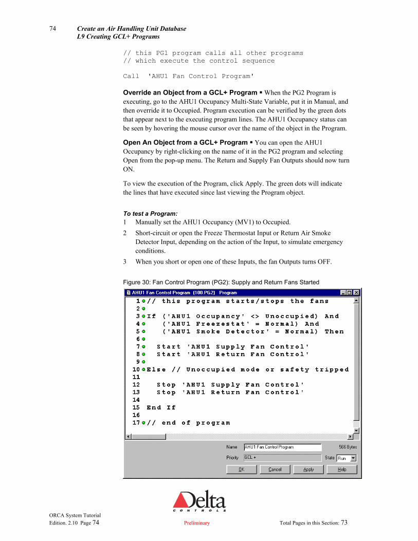
Create an Air Handling Unit Database L9 Creating GCL+ Programs
ORCA System Tutorial Edition. 2.10 Page 74 Preliminary Total Pages in this Section: 73
74
// this PG1 program calls all other programs // which execute the control sequence Call 'AHU1 Fan Control Program' Override an Object from a GCL+ Program When the PG2 Program is executing, go to the AHU1 Occupancy Multi-State Variable, put it in Manual, and then override it to Occupied. Program execution can be verified by the green dots that appear next to the executing program lines. The AHU1 Occupancy status can be seen by hovering the mouse cursor over the name of the object in the Program.
Open An Object from a GCL+ Program You can open the AHU1 Occupancy by right-clicking on the name of it in the PG2 program and selecting Open from the pop-up menu. The Return and Supply Fan Outputs should now turn ON.
To view the execution of the Program, click Apply. The green dots will indicate the lines that have executed since last viewing the Program object.
To test a Program: 1 Manually set the AHU1 Occupancy (MV1) to Occupied. 2 Short-circuit or open the Freeze Thermostat Input or Return Air Smoke
Detector Input, depending on the action of the Input, to simulate emergency conditions.
3 When you short or open one of these Inputs, the fan Outputs turns OFF. Figure 30: Fan Control Program (PG2): Supply and Return Fans Started

L9 Creating GCL+ Programs Writing GCL+ Programs to Control the System
ORCA System Tutorial
Total Pages in this Section: 73 Preliminary Edition. 2.10 Page 75
75
See Figure 30: Fan Control Program (PG2): Supply and Return Fans Stopped where the execution trace shows that both the Supply and Return fans are stopped. Lines 7 and 8 have a green dot indicating that both the AHU1 Supply Fan Control and the AHU1 Return Fan Control are started.

Create an Air Handling Unit Database L9 Creating GCL+ Programs
ORCA System Tutorial Edition. 2.10 Page 76 Preliminary Total Pages in this Section: 73
76
Programs for Tutorial (PG3-PG8) The following Programs are the remaining six programs that provide control of the system in this Tutorial. Use them as a guide.
Action: Create Programs (PG3-PG8): Now that you have created PG1 (Figure 28) and PG2 (Figure 29), you are ready to create PG3 to PG8 (Figures 31 to 36). Make sure that you call each of the programs from the Master Program (PG1).

L9 Creating GCL+ Programs Programs for Tutorial (PG3-PG8)
ORCA System Tutorial
Total Pages in this Section: 73 Preliminary Edition. 2.10 Page 77
77
PG3 Occupancy Program The PG3 program determines the Occupancy State and stores it in the AHU1 Occupancy Multi-State Variable.
Figure 31: PG3 Occupancy Program
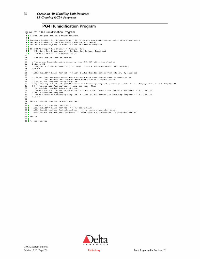
Create an Air Handling Unit Database L9 Creating GCL+ Programs
ORCA System Tutorial Edition. 2.10 Page 78 Preliminary Total Pages in this Section: 73
78
PG4 Humidification Program Figure 32: PG4 Humidification Program
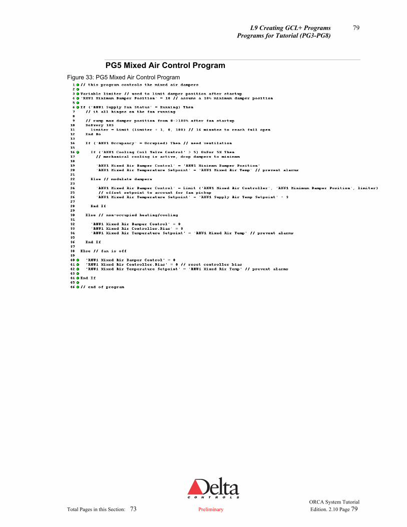
L9 Creating GCL+ Programs Programs for Tutorial (PG3-PG8)
ORCA System Tutorial
Total Pages in this Section: 73 Preliminary Edition. 2.10 Page 79
79
PG5 Mixed Air Control Program Figure 33: PG5 Mixed Air Control Program

Create an Air Handling Unit Database L9 Creating GCL+ Programs
ORCA System Tutorial Edition. 2.10 Page 80 Preliminary Total Pages in this Section: 73
80
PG6 Heating Control Program Figure 34: PG6 Heating Control Program

L9 Creating GCL+ Programs Programs for Tutorial (PG3-PG8)
ORCA System Tutorial
Total Pages in this Section: 73 Preliminary Edition. 2.10 Page 81
81
PG7 Cooling Valve Control Program Figure 35: PG7 Cooling Valve Control Program

Create an Air Handling Unit Database L9 Creating GCL+ Programs
ORCA System Tutorial Edition. 2.10 Page 82 Preliminary Total Pages in this Section: 73
82
PG8 Setpoint Control Program Figure 36: PG8 Setpoint Control Program
L9 Creating GCL+ Programs Programs for Tutorial (PG3-PG8)
ORCA System Tutorial
Total Pages in this Section: 73 Preliminary Edition. 2.10 Page 83
83
Moving On You have completed this lesson. For information on additional features of GCL+ Programming, see Chapter 11 GCL+ Programming Reference PDF file of the Technical Reference manual. Additionally, you can press the F1 Key on a field of a PG object and get specific help. Each software object has a ? Help button on the dialog in the lower right corner.
Within the GCL+ code itself, you can also select a program construct such as CALL and press F1 to get information about the CALL function.

Lesson 10 – L10 CREATING TREND LOGS AND MULTI-TRENDS
This lesson explains how to monitor the operation of your system using Trend Logs and Multi-Trends. Lesson 11 covers Alarms (Events) which monitor the operating conditions of an application. During the initial startup period, you especially need to monitor your system closely. The purpose is to verify that all the control loops are well-tuned and the overall system is running properly. You can create as many Trend Logs as you want for this tutorial. A Multi-Trend objects can display up to 8 Trend Logs on a graph.
In this lesson, you will learn how to create and use the following objects to monitor your system: Trend Logs Multi-Trends
Creating Trend Logs The Trend Log (TL) object stores data for a single object over a period of time. Trend Logs store a history of data for tuning and to verify correct short and long-term operation. This object stores data based on a specific time interval (Polling Type) or a selected amount of change (Change of Value Type) in the value being recorded.
Action: Create Trend Log objects as required You may create Trend Logs as required, however Trend Logs consume a large amount of memory. Typically the inputs, outputs, and setpoints are trended. The Trend Log object can store a maximum of 6000 samples with each data sample using approximately 10 bytes. Use the following procedure to create a Trend Log object.
To create a Trend Log 1 Right click on any white space in the right hand pane of the Navigator
window just as when creating the Inputs. From the pop-up menu, select New.... at the top of the list. The Create Object dialog window appears.
2 In the Create Object dialog box, select Trend Log (TL) from the Type of Object drop-down list.
3 Type the Object Number. For this tutorial example, select Object Number 1.
4 Type the object name in the Name field and select OK. For the tutorial example, type the name AHU1 Mixed Air Damper TL. The Object dialog window appears for the newly created Trend Log.
5 Type an Object Reference (such as 100.AI1) into the Monitored Object field. You can also drag and drop an object from the Navigator window.

L10 Creating Trend Logs and Multi-Trends Creating Trend Logs
ORCA System Tutorial
Total Pages in this Section: 34 Preliminary Edition. 2.10 Page 85
85
6 Select either Polling or Change of Value in the Log Type field. With the cursor in this field, press F1 to get specific help. The following section, Configure a Trend Log, shows sample dialogs for Change of Value and Polling Log Types. (Figures 37 and 38).
7 Click Apply or OK.
Configure a Trend Log The following are a few example Trend Logs showing the Setup tab for both Change of Value (COV) and Polling type Trend Logs.
Action: Configure Trend Log objects as required Figure 37 shows the Setup tab of the Supply Fan Status Trend Log Trend Log that monitors the starting and stopping of the supply fan. The Log Type is set to Change of Value.
Figure 37: Setup Tab of Trend Log Object (TL1) with Change of Value Log Type

Create an Air Handling Unit Database L10 Creating Trend Logs and Multi-Trends
ORCA System Tutorial Edition. 2.10 Page 86 Preliminary Total Pages in this Section: 34
86
Figure 38 shows the Setup tab of the Supply Air Temperature Trend Log Trend Log for the Supply Air Temperature. The Log Type is set to Polling.
Figure 38: Setup Tab of Trend Log Object (TL5): with Polling Log Type
Creating Multi-Trends A Multi-Trend allows you to: View or print a graph of Trend Log data. Confirm proper operation of your system by monitoring data values. Compare graphs of Trend Logs and spot abnormal behavior. Check recent data from a previous day in response to a reported problem. Troubleshoot a problem. Save data.
Action: Create the Multi-Trend objects as required The following table lists some Multi-Trends that you could create for AHU1.
Name Object Reference
AHU1 Fan MT MT1
AHU1 Supply Air Temp MT MT2

L10 Creating Trend Logs and Multi-Trends Creating Multi-Trends
ORCA System Tutorial
Total Pages in this Section: 34 Preliminary Edition. 2.10 Page 87
87
AHU1 Room Temps MT MT3
AHU1 Mixed Air Control MT MT4
AHU1 Humidification MT MT5
Use the following procedure to create a Multi-Trend object.
To create a Multi-Trend: 1 Right click on any white space in the right hand pane of the Navigator
window just as when creating the Inputs. From the pop-up menu, select New.... at the top of the list. The Create Object dialog window appears.
2 In the Create Object dialog box, select Multiple Trend Log (MT) from the Type of Object drop-down list.
3 Type the Object Number. For this tutorial example, select Object Number 1. 4 Type the object name in the Name field and select OK. For the tutorial
example, type the name AHU1 Fan MT. The Object dialog window appears for the newly created Multiple Trend.
5 Click Apply or OK.
Configure a Multi-Trend A single Multi-Trend object can display up to 8 Trend Logs on a graph.
Action: Configure Multi-Trends objects as required During the initial setup of a Multi-Trend, you can specify up to eight Trend Logs for the Multi-Trend to plot. You can just drag and drop one or more Trend Log objects from the Navigator window right onto the Multi-Trend dialog and they start to plot automatically. The Multi-Trend graphs the Trend Logs as it receives new data.
Note: By default, the drag-and-drop feature puts all analog Trend Logs (those which are monitoring an analog value) on the Y1 axis. If desired, an analog Trend Log can be graphed on the Y2 axis by clicking on the Trend Log Setup button on the toolbar and selecting Y2 for the Axis Assignment. Binary Trend Logs (those which are monitoring a binary (digital) object) automatically display on the binary axis. When you create and configure a Multi-Trend, all the options are automatically saved so that the Multi-Trend opens with the same settings.

Create an Air Handling Unit Database L10 Creating Trend Logs and Multi-Trends
ORCA System Tutorial Edition. 2.10 Page 88 Preliminary Total Pages in this Section: 34
88
To add a Trend Log to a Multi-Trend using drop and drag: Drag and Drop one or more Trend Logs from Navigator to the open Multi-
Trend object. Figure 39: AHU1 Supply Air Temp MT (MT2)
The previous Figure 39 AHU1 Supply Air Temp MT (MT2) shows graphs of the following Trend Logs: a. AHU1 Supply Air Temp TL b. AHU1 Supply Air Setpoint TL c. Heating Coil Valve TL d. Cooling Coil Valve TL e. Heating Pump Control TL f. Occupancy TL

L10 Creating Trend Logs and Multi-Trends Multi-Trend Object Components
ORCA System Tutorial
Total Pages in this Section: 34 Preliminary Edition. 2.10 Page 89
89
Multi-Trend Object Components The Multi-Trend has the following components: Axes Graph Area Graph Legend Dataview Slider Bar Toolbar Press the Help ? Button to learn about these and other features of Multi-Trend.
View a Multi-Trend You double click on a Multi-Trend object in Navigator to open and display the graphs. A Multi-Trend can graph Trend Logs with both analog and binary (digital) values. Each trended Object has its own line color to distinguish it from the others.
The Multi-Trend displays the last eight hours of Trend Log data by default. To change the view so that all of the available Trend Log data can be viewed, select the Auto button on the toolbar. This mode displays all available samples for each of the Trend Logs.
From the Auto view, the easiest way to zoom in on a specific area of the graph is to click on the Zoom In button, and then use the Back and Fwd buttons to move left and right. Click the Auto button again to return to the full view.
Note: If you modify the options of a Multi-Trend, the changes are automatically saved. When you use the Multi-Trend again, it opens in the same view as when you last closed it.
To view all the Multi-Trend data on a graph: Select Auto on the Multi-Trend toolbar.
To zoom in or zoom out on a Multi-Trend graph: Click on either the Zoom In or Zoom Out button on the Multi-Trend toolbar.
To view all data in a Multi-Trend graph by scrolling forward and backward: Press the Pause button first to activate the Back and Fwd buttons on the
Multi-Trend toolbar.

Create an Air Handling Unit Database L10 Creating Trend Logs and Multi-Trends
ORCA System Tutorial Edition. 2.10 Page 90 Preliminary Total Pages in this Section: 34
90
Tune and Troubleshoot a System A Multi-Trend object helps to tune a system during initial startup and also verifies the system during normal operation. In order to view the dynamic of an entire control system, you will have to create Trends Logs for the each Input, Setpoint, and Output. A Multi-Trend object displays up to 8 Trend Logs.
It is good practice to trend the data of important control devices. You can clearly trace the cause of a problem using the recorded Trend Log data for different values displayed in a Multi-Trend.
See the Control Loop Tuning section of Appendix A System Startup at the end of this document for more information.
Moving On You have completed this lesson. For information on additional features of Trend Log and Multi-Trend objects, see Chapter 6 Trending Archiving and Reporting PDF file of the Technical Reference manual. Additionally, you can press the F1 Key on a field and get specific help. Each software object has a ? Help button on the dialog in the lower right corner.
L11 Creating Alarms (Events) Introduction: Common BACnet Event Types
ORCA System Tutorial
Total Pages in this Section: 34 Preliminary Edition. 2.10 Page 91
91
Lesson 11 – L11 CREATING ALARMS (EVENTS)
The Event (EV) object monitors an object such as an analog input or binary variable. An Event occurs if a value is outside of the defined operating ranges or conditions. The system responds as specified in the Event. Event objects generate Alarm Notifications based on either, Change of State (COS), Command Failure, Floating Limit, or Out of Range alarm types.
The main purpose of the Event object is to provide a method for setting up what warrants an Alarm Notification. An Event determines when the control system detects abnormal operating conditions. If a value is outside of the defined operating ranges or conditions, then the Event Management System sends an Alarm Notification. The operator can acknowledge the alarm.
In this lesson, you will learn how to: Describe the function of the four most common Alarm Types. Describe the meaning of the seven Event object states. Monitor your system using Events (Alarms) objects.
Introduction: Common BACnet Event Types The Event Type defines the function and the fields of the Setup tab on the Event object. Each Event Type is designed to suit a particular kind of application. The fields and parameters on the dialog, change based on the selected Alarm Type. The monitored object specifies the value that the Event tests to see if it is within defined operating conditions.
The following table explains the four most common Alarm (Event) types:
Event Type Monitored Value Typical Function and Example
Out of Range Analog An Out of Range alarm type monitors whether an analog object value is within fixed high and low limits.
For example, an Out of Range alarm type might detect if the Mixed Air temperature is near freezing and generate an Alarm Notification before the digital freeze status indicator trips.
Floating Limit Analog The Floating Limit alarm type compares an input with its setpoint using high and low limits based on the setpoint value.
For example, a Floating Limit alarm type can detect if the room temperature is 3 degrees above or below the setpoint for the room.

Create an Air Handling Unit Database L11 Creating Alarms (Events)
ORCA System Tutorial Edition. 2.10 Page 92 Preliminary Total Pages in this Section: 34
92
Change of State Binary (digital) The Change of State alarm type monitors a Binary Input (digital) and notifies when the input state changes.
For example, a Change of State alarm type might monitor if a filter alarm changes from Clean to Dirty. Also this alarm type is typically used with a smoke detector or a freeze status indicator.
Command Failure Binary (digital) The Command Failure alarm type confirms that two values match. The Command Failure alarm type is used in situations where it must be confirmed that one object is controlling another.
For example, a Command Failure alarm type monitors a flow switch to detect if a fan that was commanded ON has an OFF status.
The Event object can have a number of states.
State Alarm Type Meaning
Normal All The monitored value is operating as expected.
Pending All The monitored value is outside its limits but the Time Delay has not expired.
Alarm Change of State / Command Failure
Alarm
High Limit Out of Range / Floating Limit
Alarm
Low Limit Out of Range / Floating Limit
Alarm
Fault All A sensor is malfunctioning.
Return to Normal All The monitored value makes a transition back to normal from an alarm condition.
L11 Creating Alarms (Events) Creating an Event
ORCA System Tutorial
Total Pages in this Section: 34 Preliminary Edition. 2.10 Page 93
93
Creating an Event An Event detects abnormal operating conditions.
Action: Create Event objects (EV1-EV10) The following table lists ten Event objects that help to monitor the AHU1 Air Handler.
List of Events (Alarms) EV1-EV8
Name Type Object Reference
AHU1 Supply Fan Alarm Command Failure
EV1
AHU1 Return Fan Alarm Command Failure
EV2
AHU1 Supply Air Temp Alarm Out of Range
EV3
AHU1 Mixed Air Temp Alarm Out of Range
EV4
AHU1 Return Air Humidity Alarm Out of Range
EV5
AHU1 Freezestat Alarm
Change of State
EV6
AHU1 Smoke Detector Alarm Change of State
EV7
AHU1 Filter Alarm Change of State
EV8
AHU1 Room 1 Temperature Alarm
Floating Limit
EV9
AHU1 Room 2 Temperature Alarm
Floating Limit
EV10
After you create each Event object, you need to configure the following tabs: a. Setup (Figures 40-50 show the fields) b. Messages (Figure 51 in Configure Messages Tab section) c. Event Class (Configure Event Class tab section)
The following procedure explains how to create EV1 which is a Command Failure Event.
Create an Air Handling Unit Database L11 Creating Alarms (Events)
ORCA System Tutorial Edition. 2.10 Page 94 Preliminary Total Pages in this Section: 34
94
To create and configure a Command Failure Event: Follow the instructions below to configure a Command Failure alarm. This example outlines an alarm that generates a notification if the Supply Fan Status does not come on when Supply Fan Control does.
1 Right click on any white space in the right hand pane of the Navigator window just as when creating the Inputs. From the pop-up menu, select New.... at the top of the list. The Create Object dialog window appears.
2 In the Create Object dialog box, select Event (EV) from the Type of Object drop-down list.
3 Type the Object Number. For this tutorial example, select Object Number 1. 4 Type the object name in the Name field and select OK.
For the tutorial example, type the name AHU1 Supply Fan Alarm. The Object dialog window appears for the newly created Event.
5 From the Setup tab, select the Command Failure Alarm Type. The fields on the Setup tab changes depending on the Alarm Type.
6 Type an Object Reference (such as 100.BI1) into the Alarm Input field. You can also drag and drop an object such as Supply Fan Status (BI1) from the Navigator window.
7 Type an Object Reference (such as 100.BO1) into the Feedback (Object Reference) field. You can also drag and drop an object such as Supply Fan Control (BO1) from the Navigator window.
8 Adjust the Time Delay. 9 Click OK.

L11 Creating Alarms (Events) Creating an Event
ORCA System Tutorial
Total Pages in this Section: 34 Preliminary Edition. 2.10 Page 95
95
Figure 40: Setup Tab of Supply Fan Command Failure Alarm (EV1)

Create an Air Handling Unit Database L11 Creating Alarms (Events)
ORCA System Tutorial Edition. 2.10 Page 96 Preliminary Total Pages in this Section: 34
96
Action: Configure Event objects (EV1-EV10) Setup tab An Event is configured so that abnormal operating conditions are defined. The following figures (41-50) shows the Setup Tab information for Events 1-10.
Figure 41: Setup Tab of AHU1 Supply Fan Alarm (EV1)
Figure 42: Setup Tab of AHU1 Return Fan Alarm (EV2)

L11 Creating Alarms (Events) Creating an Event
ORCA System Tutorial
Total Pages in this Section: 34 Preliminary Edition. 2.10 Page 97
97
Figure 43: Setup Tab of AHU1 Supply Air Temp Alarm (EV3)
Figure 44: Setup Tab of AHU1 Mixed Air Temp Alarm (EV4)

Create an Air Handling Unit Database L11 Creating Alarms (Events)
ORCA System Tutorial Edition. 2.10 Page 98 Preliminary Total Pages in this Section: 34
98
Figure 45: Setup Tab of AHU1 Return Air Humidity Alarm (EV5)
Figure 46: Setup Tab of AHU1 Freezestat Alarm (EV6)

L11 Creating Alarms (Events) Creating an Event
ORCA System Tutorial
Total Pages in this Section: 34 Preliminary Edition. 2.10 Page 99
99
Figure 47: Setup Tab of AHU1 Smoke Detector Alarm (EV7)
Figure 48: Setup Tab of AHU1 Filter Alarm (EV8)

Create an Air Handling Unit Database L11 Creating Alarms (Events)
ORCA System Tutorial Edition. 2.10 Page 100 Preliminary Total Pages in this Section: 34
100
Figure 49: Setup Tab of AHU1 Room 1 Temperature Alarm (EV9)
Figure 50: Setup Tab of AHU1 Room 2 Temperature Alarm (EV10)

L11 Creating Alarms (Events) Creating an Event
ORCA System Tutorial
Total Pages in this Section: 34 Preliminary Edition. 2.10 Page 101
101
Configure Messages Tab The messages for an alarm transition can be set on the Messages tab of the Event object. With DSC and DAC controllers, the option to use Auto-Generated messages is available.
Action: Configure Event objects (EV1-EV10) Messages tab The following figure (51) shows the Messages tab for AHU1 Room 1 Temperature Alarm (EV9).
Figure 51: Messages Tab of Room 1 Temperature Floating Limit Alarm (EV9)
To get more information about a field on the Event object, put the cursor in the field, and press the F1 function key.
Configure Event Class Tab When you create an Event object, select an appropriate Event Class on the Event Class tab. The default options are Maintenance, Network, Security, Critical, Notification and Fire.

Create an Air Handling Unit Database L11 Creating Alarms (Events)
ORCA System Tutorial Edition. 2.10 Page 102 Preliminary Total Pages in this Section: 34
102
Action: Configure Event objects (EV1-EV10) Event Class tab In the tutorial, AHU1 Smoke Detector Alarm (EV7) is set to Fire. All the Event objects are set to the default Event Class value of Maintenance.
Moving On You have completed this lesson. For information on additional features of Event object, see Chapter 10 Software Object Reference PDF file of the Technical Reference manual. Chapter 5 Event Management System provides detailed information on using alarm features. Additionally, you can press the F1 Key on a field and get specific help. Each software object has a ? Help button on the dialog in the lower right corner.
L11 Creating Alarms (Events) Creating an Event
ORCA System Tutorial
Total Pages in this Section: 34 Preliminary Edition. 2.10 Page 103
103
GRAPHICS OPTION The ORCAview Illustrator drawing tool is an optional application that allows you to create, edit and display custom site graphic drawings. The graphical interface links controller objects to site graphics and provides control and interaction with these objects via live data displays and command graphics. With illustrator, you can create and edit links on pictures, equipment photos, buttons, or icons contained in a site graphic drawing. A site graphic is not necessary for the control system to work.
Action: Copy and then open the Demokit_AHU.gpc file You can see the tutorial database linked to a graphical interface created using the optional ORCAview drawing program called Illustrator.
From the CD, copy the Demokit_AHU.gpc file and the associated .bmp files to the Graphics folder of your site.
The following procedure tells how to open a site graphic.
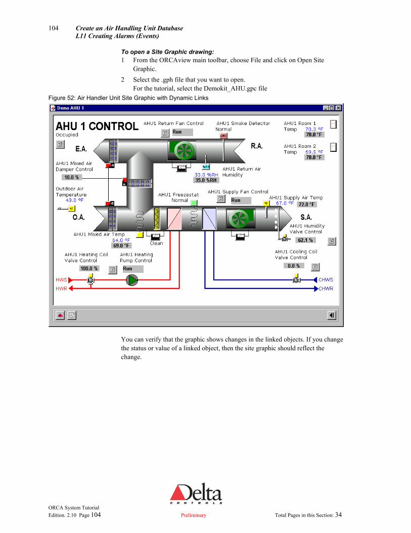
Create an Air Handling Unit Database L11 Creating Alarms (Events)
ORCA System Tutorial Edition. 2.10 Page 104 Preliminary Total Pages in this Section: 34
104
To open a Site Graphic drawing: 1 From the ORCAview main toolbar, choose File and click on Open Site
Graphic. 2 Select the .gph file that you want to open.
For the tutorial, select the Demokit_AHU.gpc file Figure 52: Air Handler Unit Site Graphic with Dynamic Links
You can verify that the graphic shows changes in the linked objects. If you change the status or value of a linked object, then the site graphic should reflect the change.

L11 Creating Alarms (Events) Tuning a Control Loop
ORCA System Tutorial
Total Pages in this Section: 34 Preliminary Edition. 2.10 Page 105
105
Appendix A – SYSTEM STARTUP This appendix describes one approach to the tuning of control loops.
Tuning a Control Loop A Control Loop needs tuning to ensure that it provides good performance for the particular control system.
Tune a Loop Using a Multi-Trend You can tune a control loop using a Multi-Trend graph that displays up to 8 Trend Logs. The oscillations that appear on the graph of trended data indicate that values in the Controller object need adjustment.
The control loop is tuned for a PI controller. Derivative action is usually implemented in controls which have a quick response time. Thus, derivative action is not usually used in building control systems.
A PI controller adjusts the HVAC system using a feedback loop with a Proportional Band and a Reset action. When these two factors are properly set, the room temperature remains stable. The reset action consists of a Reset Band and a Reset Rate that act together to adjust the amount of bias added to the proportional action of the controller.
It is helpful to define the following terms:
Proportional Band The range over which the input must vary to cause a change in the controller output from to 0 to 100 %. The Proportional Band is centered around the setpoint.
Output Bias: The Controller Output is equal to the output Bias when the Input is equal to the Setpoint. In a Proportional Only Controller (i.e., when the Controller Type is P only), or when the Reset Rate is set to 0.0, the Output Bias remains fixed (normally at 50.0%) and is not adjusted by Reset action.
When a Controller is defined with Reset action, the Output Bias is continuously adjusted until the Input is as close to the Setpoint as possible.
Reset Band The Reset Band provides a dynamic means to adjust the amount of Output Bias added to the controller output. When the Input is outside of the Reset Band, the effective reset rate is equal to the specified Reset Rate. When the Input is within the Reset Band, the effective Reset Rate is proportionally reduced. When the Input is within the Deadband, no further reset action occurs.

Create an Air Handling Unit Database L11 Creating Alarms (Events)
ORCA System Tutorial Edition. 2.10 Page 106 Preliminary Total Pages in this Section: 34
106
Reset Rate The Reset Rate determines how fast the controller bias is adjusted to make the necessary correction so that there is no offset between the signal and the setpoint. The Reset Rate is defined as the amount of bias change during one minute. It is expressed as percentage change per minute – not repeats per hour as in previous versions of Delta Controls software.
Dad band The deadband is a small range in which variation of the temperature is allowed. When the input is within the Deadband, the proportional component of the controller output is fixed at 0%. When the input is within the Deadband area, the controller value will only change due to reset action—which increments and decrements the bias.
Deadbands should be small enough so that the occupant does not notice the temperature variations within the deadband. If a deadband is too small, then the analog machinery will make frequent adjustments that cause wear and premature failure of moving components.

L11 Creating Alarms (Events) Tuning a Control Loop
ORCA System Tutorial
Total Pages in this Section: 34 Preliminary Edition. 2.10 Page 107
107
Tune a Controller Typical values for Deadband are rarely above 1 C (0.5 F).
Within the span of the Deadband (around Setpoint), the controller does not change its output. The intention is to prevent unnecessary modulation of valve and damper actuators, which could cause premature wear.
To tune a controller:
1 Set both the Reset Rate and Derivative Gain to 0.0 to eliminate any reset or derivative action.
2 Adjust the Proportional Band as follows: If the Controller is unstable, widen the Proportional Band until the
Controller is stabilized. If the Controller stabilizes, reduce the Proportional Band until the
Controller becomes unstable. Increase the Band until the Controller stabilizes again.
3 Introduce a Setpoint change and observe the Controller response. If the Controller does not stabilize as desired, then increase/decrease the Proportional Band slightly and repeat this step.
4 As a rule of thumb, set the Reset Band to 1/4 of the Proportional Band. 5 Increase the Reset Rate gradually until the input reaches Setpoint. Be sure not
to set the Reset Rate too high. This could cause the Controller to react faster than the controlled variable can respond to a Controller output change and create instability.
6 Once the Controller appears to have stabilized and the input is close to the Setpoint, introduce a change to the Setpoint and observe the response of the control loop. If the Controller does not stabilize, reduce the Reset Rate and repeat this step.
7 Introduce appropriate Derivative action only if the application is suitable and warrants it. Introduce a Setpoint change and observe the response to the control loop.
8 If at any point oscillation begins to occur on the output, suspect that either the Derivative or Reset gains are too high or that the Proportional Band is too narrow. Try decreasing the Derivative and Reset Rate values first.
A control loop is tuned to the conditions that exist at the time of tuning (both setpoint and load conditions). It may be necessary to tune a controller at a later date if the conditions change. This is particularly true for the load conditions (i.e., the difference between an unoccupied building and when it has been occupied with people and equipment and lights have been turned on). There may also be seasonal considerations. By not tuning too tightly, it is possible to alleviate the necessity of re-tuning.
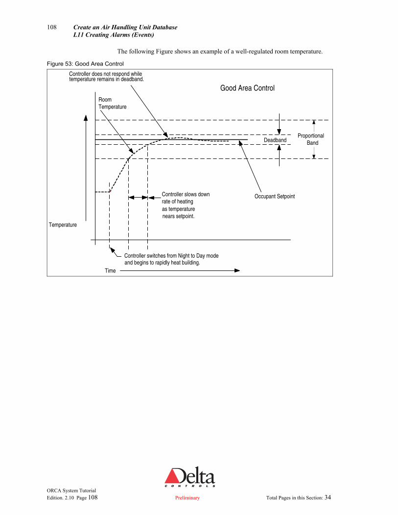
Create an Air Handling Unit Database L11 Creating Alarms (Events)
ORCA System Tutorial Edition. 2.10 Page 108 Preliminary Total Pages in this Section: 34
108
The following Figure shows an example of a well-regulated room temperature.
Figure 53: Good Area Control
temperature remains in deadband.Controller does not respond while
and begins to rapidly heat building.Controller switches from Night to Day mode
Occupant Setpoint
Time
Temperature
ProportionalBand
as temperaturenears setpoint.
Controller slows downrate of heating
RoomTemperature
Deadband
Good Area Control

L11 Creating Alarms (Events) Tuning a Control Loop
ORCA System Tutorial
Total Pages in this Section: 34 Preliminary Edition. 2.10 Page 109
109
Problem: Cycling If the controller is not tuned properly, then it may cycle rapidly from heating to cooling. The following Figure shows cycling.
Figure 54: Cycling
Temperature
Time
Room Temperature
delay
and overshoots setpoint.Heating does not throttle back
Deadband
Occupant Setpoint
Cooling does notthrottle back andovershoots setpoint.
Cycling
Solution: Cycling In this example, the Controller setpoints could be changed as follows:
Check that the proportional bands for both heating and cooling are wide enough to allow the system enough time to throttle down as it approaches the deadband.
The proportional bands need to be wider than normal in the following circumstances:
The damper and the heating coil are distant from the controlled area;
The area receives heat from other sources such as machinery, sunlight or personnel; and,
The area looses heat because of large windows or poor insulation.
Check that the reset rate is set properly. The Reset Rate controls the integral gain of the Controller. A high integral gain can also cause cycling.

Create an Air Handling Unit Database L11 Creating Alarms (Events)
ORCA System Tutorial Edition. 2.10 Page 110 Preliminary Total Pages in this Section: 34
110
Problem: Controller Unable to Reach Setpoint If the Controller is set incorrectly, it is unable to maintain the correct temperature.
Figure 55: Controller Does Not Reach Setpoint
Room Temperature
CoolingSystem On
Occupant Setpoint
Deadband
Time
Temperature
Controller Does Not ReachSetpoint
CoolingSystem On
Solution: Controller Unable to Maintain Setpoint In the figure, the cooling system is unable to reach the temperature set by the occupant. Although the cooling system turns on, it does not bring the room to the correct temperature before turning off.
In this example, the common solution is to set the reset rate higher. With an insufficient reset rate, the system will not correct small differences that persist over a long period of time.

L11 Creating Alarms (Events) Tuning a Control Loop
ORCA System Tutorial
Total Pages in this Section: 34 Preliminary Edition. 2.10 Page 111
111
Appendix B – INSTALL SENTINEL DRIVERS The Sentinel Drivers work with the software key. You may need to manually install or update the Sentinel Driver System.
Install Sentinel Drivers The Sentinel drivers are included on the ORCAview CD-ROM in the Utilities\Rainbow Sentinel Driver folder.
To install the Sentinel driver from the ORCAview CD-ROM: 1 Close all programs. 2 Insert the CD-ROM into the CD-ROM drive. 3 Use the My Computer icon or Explorer to view the contents of the CD-ROM. 4 Open the Utilities\Rainbow Sentinel Driver folder on the release CD. 5 Find a file like Rainbow_SSD.exe and double click it. 6 Sentinel System Driver – InstallShield Wizard
Click Next to continue.
Note: If you are using a USB software key with Windows 98, you are prompted to install the Sentinel Drivers. The parallel software key does not require drivers on Windows 98
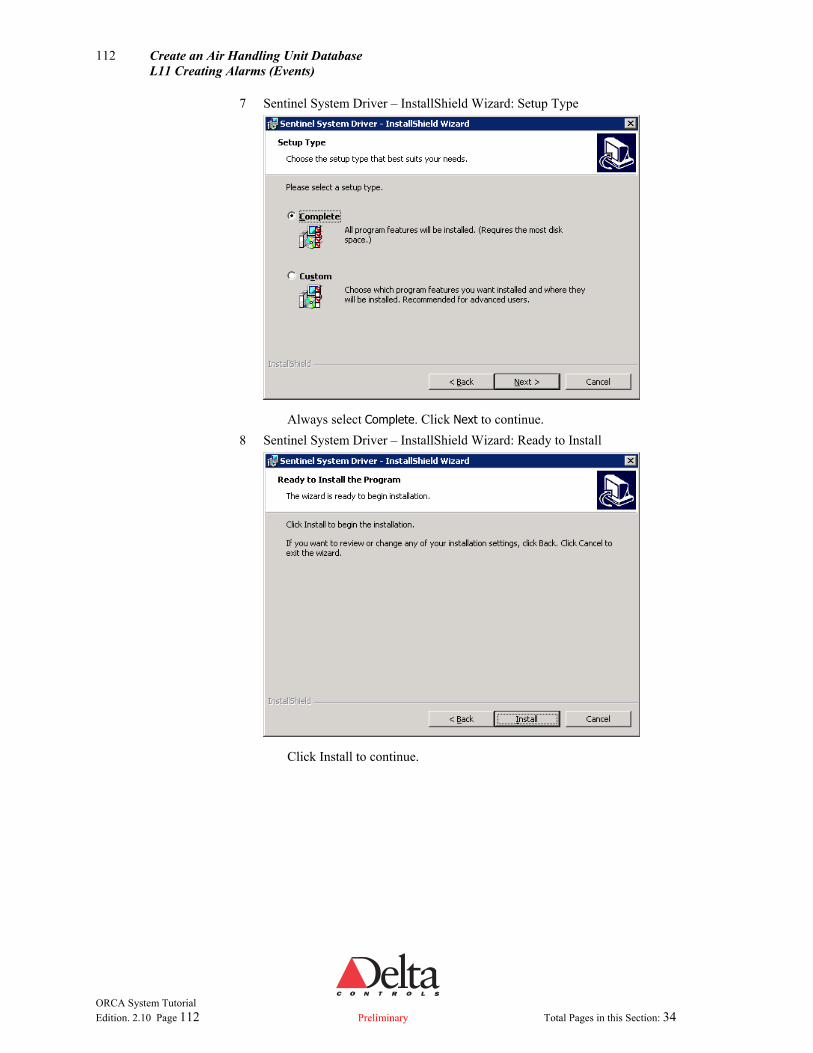
Create an Air Handling Unit Database L11 Creating Alarms (Events)
ORCA System Tutorial Edition. 2.10 Page 112 Preliminary Total Pages in this Section: 34
112
7 Sentinel System Driver – InstallShield Wizard: Setup Type
Always select Complete. Click Next to continue. 8 Sentinel System Driver – InstallShield Wizard: Ready to Install
Click Install to continue.
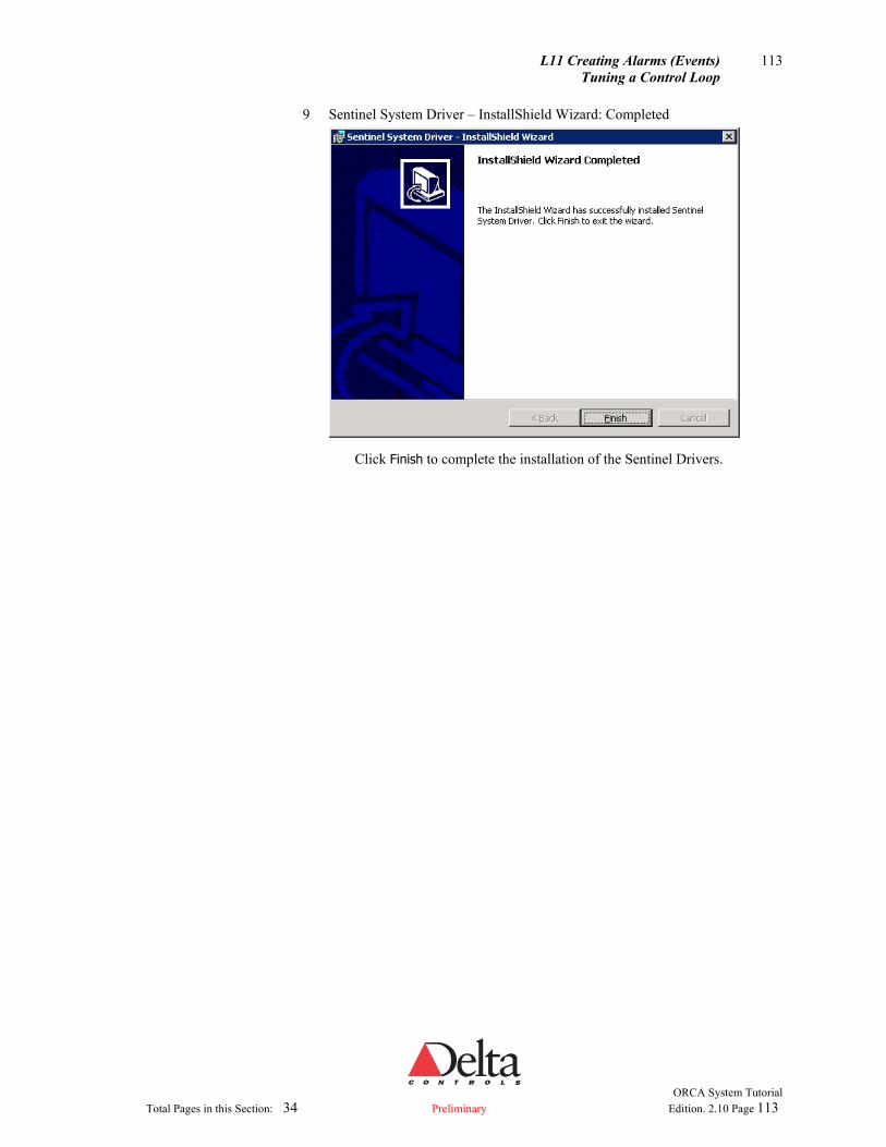
L11 Creating Alarms (Events) Tuning a Control Loop
ORCA System Tutorial
Total Pages in this Section: 34 Preliminary Edition. 2.10 Page 113
113
9 Sentinel System Driver – InstallShield Wizard: Completed
Click Finish to complete the installation of the Sentinel Drivers.
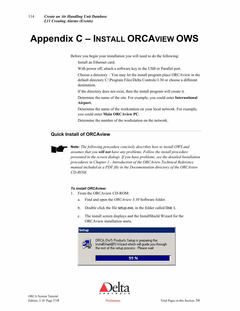
Create an Air Handling Unit Database L11 Creating Alarms (Events)
ORCA System Tutorial Edition. 2.10 Page 114 Preliminary Total Pages in this Section: 34
114
Appendix C – INSTALL ORCAVIEW OWS Before you begin your installation you will need to do the following: Install an Ethernet card. With power off, attach a software key to the USB or Parallel port. Choose a directory – You may let the install program place ORCAview in the
default directory C:\Program Files\Delta Controls\3.30 or choose a different destination. If the directory does not exist, then the install program will create it.
Determine the name of the site. For example, you could enter International Airport.
Determine the name of the workstation on your local network. For example, you could enter Main ORCAview PC.
Determine the number of the workstation on the network.
Quick Install of ORCAview
Note: The following procedure concisely describes how to install OWS and assumes that you will not have any problems. Follow the install procedure presented in the screen dialogs. If you have problems, see the detailed Installation procedures in Chapter 1 - Introduction of the ORCAview Technical Reference manual included as a PDF file in the Documentation directory of the ORCAview CD-ROM.
To install ORCAview: 1. From the ORCAview CD-ROM:
a. Find and open the ORCAview 3.30 Software folder.
b. Double click the file setup.exe, in the folder called Disk 1.
c. The install screen displays and the InstallShield Wizard for the ORCAview installation starts.
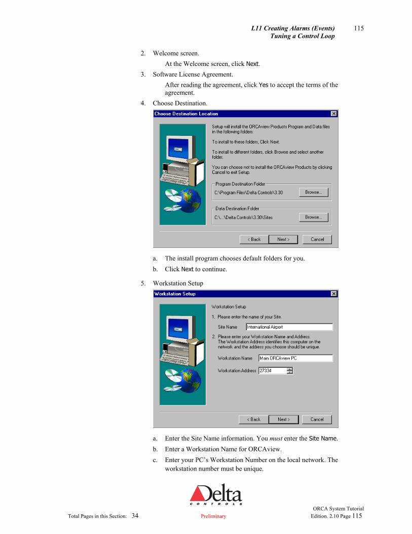
L11 Creating Alarms (Events) Tuning a Control Loop
ORCA System Tutorial
Total Pages in this Section: 34 Preliminary Edition. 2.10 Page 115
115
2. Welcome screen. At the Welcome screen, click Next.
3. Software License Agreement. After reading the agreement, click Yes to accept the terms of the
agreement. 4. Choose Destination.
a. The install program chooses default folders for you. b. Click Next to continue.
5. Workstation Setup
a. Enter the Site Name information. You must enter the Site Name. b. Enter a Workstation Name for ORCAview. c. Enter your PC’s Workstation Number on the local network. The
workstation number must be unique.
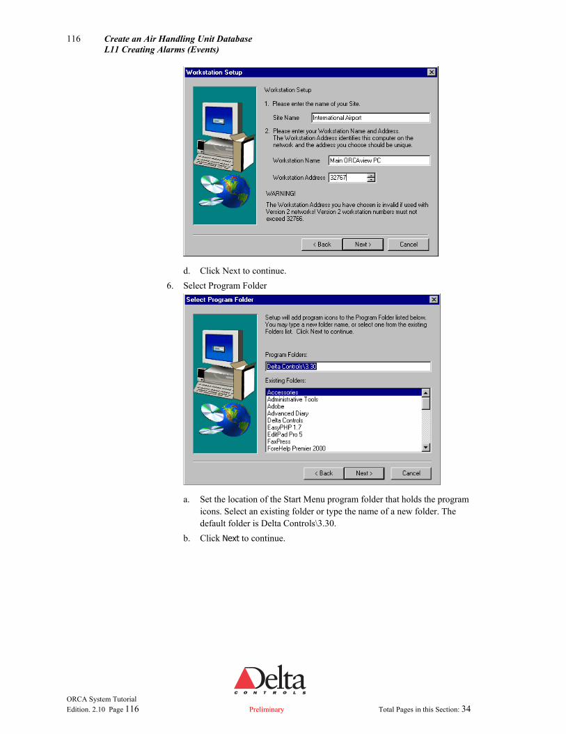
Create an Air Handling Unit Database L11 Creating Alarms (Events)
ORCA System Tutorial Edition. 2.10 Page 116 Preliminary Total Pages in this Section: 34
116
d. Click Next to continue. 6. Select Program Folder
a. Set the location of the Start Menu program folder that holds the program icons. Select an existing folder or type the name of a new folder. The default folder is Delta Controls\3.30.
b. Click Next to continue.
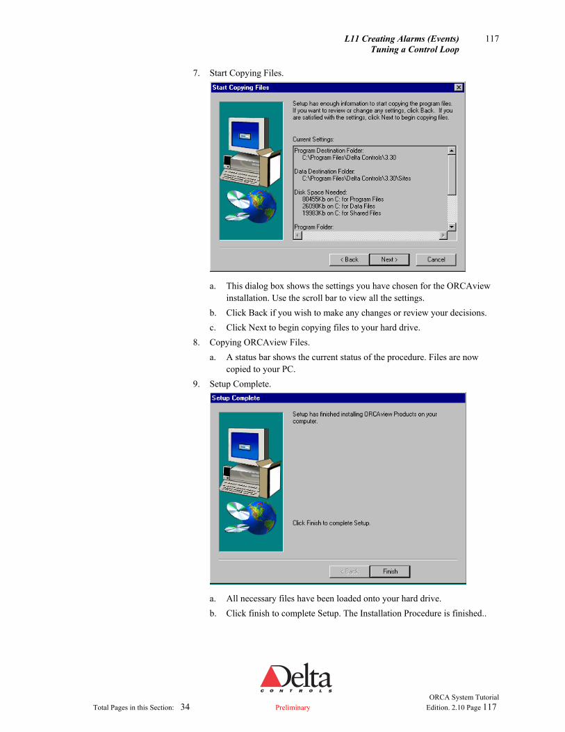
L11 Creating Alarms (Events) Tuning a Control Loop
ORCA System Tutorial
Total Pages in this Section: 34 Preliminary Edition. 2.10 Page 117
117
7. Start Copying Files.
a. This dialog box shows the settings you have chosen for the ORCAview installation. Use the scroll bar to view all the settings.
b. Click Back if you wish to make any changes or review your decisions. c. Click Next to begin copying files to your hard drive.
8. Copying ORCAview Files. a. A status bar shows the current status of the procedure. Files are now
copied to your PC. 9. Setup Complete.
a. All necessary files have been loaded onto your hard drive. b. Click finish to complete Setup. The Installation Procedure is finished..