03 - sd-sy-ai-0014_1 functional and technical spec
TRANSCRIPT
CONTROLLED DISTRIBUTION REFERENCE : DATE :
SD-SY-AI-0014 June 09
ISSUE : 01 PAGE : 1/72
All rights reserved, 2007, Thales Alenia Space
100181547K-EN
M032-EN
CONTROLLED DISTRIBUTION
GALILEO GALILEI (GG)
SYSTEM FUNCTIONAL SPECIFICATION
AND PRELIMINARY SYSTEM TECHNICAL
SPECIFICATION
DRL/DRD: DEL-022
Written by Responsibility
F. Amisano Author
Verified by
A. Anselmi Checker
Approved by
Product Assurance
Configuration Control
Design Engineer
System Engineering Manager
A. Anselmi Study Manager
Documentation Manager
R. Cavaglià
The validations evidence are kept through the documentation management system.
CONTROLLED DISTRIBUTION REFERENCE : DATE :
SD-SY-AI-0014 June 09
ISSUE : 01 PAGE : 2/72
All rights reserved, 2007, Thales Alenia Space
100181547K-EN
M032-EN
CONTROLLED DISTRIBUTION
CHANGE RECORDS
ISSUE DATE § CHANGE RECORDS AUTHOR
Draft January 09 Draft issue of preliminary system technical specification 1 June 09 Update Definition of a single document encompassing
system functional specification and preliminary system technical specification
CONTROLLED DISTRIBUTION REFERENCE : DATE :
SD-SY-AI-0014 June 09
ISSUE : 01 PAGE : 3/72
All rights reserved, 2007, Thales Alenia Space
100181547K-EN
M032-EN
CONTROLLED DISTRIBUTION
TABLE OF CONTENTS
1. INTRODUCTION ..............................................................................................................7
1.1 Background .................................................................................................................................... 7
1.2 Structure of the document .............................................................................................................. 7
1.3 Requirements Identification............................................................................................................ 8
2. MISSION DESCRIPTION................................................................................................10
2.1 Scientific Objectives..................................................................................................................... 10
2.2 Experiment Description ................................................................................................................ 10
2.3 System Description ...................................................................................................................... 11 2.3.1 System Elements ....................................................................................................................... 11 2.3.2 Payload ..................................................................................................................................... 11
2.4 Mission Design ............................................................................................................................. 12 2.4.1 Mission Overview ....................................................................................................................... 12 2.4.2 Mission Phases .......................................................................................................................... 12
2.4.2.1 General.............................................................................................................................. 12 2.4.2.2 Launch and Early Orbit Phase ............................................................................................. 13 2.4.2.3 Orbit Phase........................................................................................................................ 13 2.4.2.4 Disposal Phase .................................................................................................................. 13
2.4.3 Orbit Parameters........................................................................................................................ 13
3. SYSTEM FUNCTIONAL REQUIREMENTS.....................................................................14
3.1 General functional requirements .................................................................................................. 14
3.2 Preparation and programming of the measurements ................................................................... 15
3.3 Recording, downloading and transmission of the data ................................................................ 15
3.4 Processing, calibration and distribution of the scientific data ..................................................... 16
4. SYSTEM REQUIREMENTS............................................................................................17
4.1 Physical Requirements................................................................................................................. 17 4.1.1 Units.......................................................................................................................................... 17 4.1.2 Co-ordinate Systems .................................................................................................................. 17
4.1.2.1 General.............................................................................................................................. 17 4.1.2.2 Satellite Physical Reference Frame ..................................................................................... 17 4.1.2.3 Payload Physical Reference Frame ..................................................................................... 18 4.1.2.4 Inertial Orbit Reference Frame ............................................................................................ 18 4.1.2.5 Rotating Orbit Reference Frame .......................................................................................... 18
4.1.3 Spacecraft Resource Requirements............................................................................................. 19 4.1.3.1 General.............................................................................................................................. 19
CONTROLLED DISTRIBUTION REFERENCE : DATE :
SD-SY-AI-0014 June 09
ISSUE : 01 PAGE : 4/72
All rights reserved, 2007, Thales Alenia Space
100181547K-EN
M032-EN
CONTROLLED DISTRIBUTION
4.1.3.2 System Margin Requirements.............................................................................................. 20
4.2 Environmental Requirements ....................................................................................................... 21 4.2.1 General...................................................................................................................................... 21 4.2.2 Mechanical Environment ............................................................................................................. 21 4.2.3 Thermal Environment.................................................................................................................. 22 4.2.4 Cleanliness and Contamination ................................................................................................... 22 4.2.5 Radiation Environment................................................................................................................ 22 4.2.6 Micro-meteorite Environment....................................................................................................... 23
4.3 Mission Requirements.................................................................................................................. 23 4.3.1 General...................................................................................................................................... 23 4.3.2 Launch and Early Orbit Phase ..................................................................................................... 23 4.3.3 Commissioning Phase ................................................................................................................ 24 4.3.4 Orbit Phase................................................................................................................................ 24 4.3.5 Disposal Phase .......................................................................................................................... 24
4.4 Experiment Requirements ............................................................................................................ 25
4.5 Spacecraft Requirements ............................................................................................................. 25 4.5.1 General Requirements................................................................................................................ 25
4.5.1.1 Overall Design Approach Requirements............................................................................... 25 4.5.1.2 Lifetime Requirements ........................................................................................................ 25 4.5.1.3 Pointing and Stability Requirements..................................................................................... 26 4.5.1.4 Payload Interface Requirements.......................................................................................... 28
4.5.2 Command & Control Requirements.............................................................................................. 28 4.5.2.1 General Requirements........................................................................................................ 28 4.5.2.2 Spacecraft Control Requirements ........................................................................................ 29 4.5.2.3 Spacecraft Modes............................................................................................................... 29 4.5.2.4 Autonomy, FDIR (Redundancy Management) and Safe Mode ............................................... 30 4.5.2.5 General Functional Requirements........................................................................................ 37 4.5.2.6 Packet and Functional Requirements by Service .................................................................. 40
4.5.3 Communications Requirements ................................................................................................... 42 4.5.3.1 General Requirements........................................................................................................ 42 4.5.3.2 Functional Requirements .................................................................................................... 42
4.5.4 Attitude and Orbit Control Requirements ...................................................................................... 42 4.5.4.1 Functional Requirements .................................................................................................... 42 4.5.4.2 Design Requirements ......................................................................................................... 43
4.5.5 Electrical and Electronic Engineering Requirements ..................................................................... 43 4.5.5.1 Electrical Power Requirements............................................................................................ 43 4.5.5.2 Electromagnetic Compatibility (EMC)................................................................................... 53
4.5.6 Radio Frequency Systems .......................................................................................................... 57 4.5.7 Mechanical Engineering Requirements ........................................................................................ 58
4.5.7.1 Thermal Control Requirements............................................................................................ 58 4.5.7.2 Structural Requirements ..................................................................................................... 59 4.5.7.3 Mechanisms Requirements ................................................................................................. 61 4.5.7.4 Propulsion Requirements .................................................................................................... 62 4.5.7.5 Pyrotechnics Requirements................................................................................................. 63 4.5.7.6 Mechanical Parts Requirements .......................................................................................... 63 4.5.7.7 Materials Requirements ...................................................................................................... 63
4.5.8 Software Engineering Requirements............................................................................................ 63 4.5.8.1 Software Design................................................................................................................. 63 4.5.8.2 Software Test and Validation............................................................................................... 64 4.5.8.3 Software Design and Implementation................................................................................... 65
4.6 Launch Service Segment Interface Requirements........................................................................ 65
CONTROLLED DISTRIBUTION REFERENCE : DATE :
SD-SY-AI-0014 June 09
ISSUE : 01 PAGE : 5/72
All rights reserved, 2007, Thales Alenia Space
100181547K-EN
M032-EN
CONTROLLED DISTRIBUTION
5. GROUND SEGMENT REQUIREMENTS.........................................................................66
6. VERIFICATION REQUIREMENTS..................................................................................67
7. PRODUCT ASSURANCE REQUIREMENTS ..................................................................68
8. DOCUMENTS ................................................................................................................69
8.1 Overview....................................................................................................................................... 69
8.2 Applicable Documents ................................................................................................................. 69
8.3 Standards ..................................................................................................................................... 69
8.4 Reference Documents .................................................................................................................. 70
9. ACRONYMS...................................................................................................................71
CONTROLLED DISTRIBUTION REFERENCE : DATE :
SD-SY-AI-0014 June 09
ISSUE : 01 PAGE : 6/72
All rights reserved, 2007, Thales Alenia Space
100181547K-EN
M032-EN
CONTROLLED DISTRIBUTION
List Of Tables
TABLE 1.3-1: REQUIREMENTS IDS FOR SYSTEM TECHNICAL SPECIFICATION DOCUMENT 9 TABLE 4.1-1: SATELLITE PHYSICAL REFERENCE FRAME DEFINITION 17 TABLE 4.1-2: INERTIAL ORBIT REFERENCE FRAME DEFINITION 18 TABLE 4.1-3: ROTATING ORBIT REFERENCE FRAME DEFINITION 18 TABLE 4.1-4: LAUNCH VEHICLE PERFORMANCE (REFERENCE VALUES) 19 TABLE 4.1-5: DESIGN MATURITY MARGINS 21 TABLE 4.5-1: APPLICABLE GG PACKET SERVICE TYPES 41
List Of Figures
FIGURE 4.1-1: PAYLOAD MASS VS. EQUATORIAL ORBIT ALTITUDE (REFERENCE LAUNCHER PERFORMANCES) 19 FIGURE 4.5-1: ILLUSTRATION OF POINTING AND MEASUREMENT ERRORS 27 FIGURE 4.5-2: IMPEDANCE MASK FOR POWER REGULATION 51
CONTROLLED DISTRIBUTION REFERENCE : DATE :
SD-SY-AI-0014 June 09
ISSUE : 01 PAGE : 7/72
All rights reserved, 2007, Thales Alenia Space
100181547K-EN
M032-EN
CONTROLLED DISTRIBUTION
1. INTRODUCTION
1.1 Background
The Galileo Galilei (GG) mission is a part of the Cosmology and Fundamental Physics project of the ASI Unit on Observation of the Universe, the purpose of which is providing support to the Italian Scientific Community in its participation in the European and worldwide development of knowledge in this field, both by independent projects and by international collaboration.
GG participates in the worldwide programme of verifying the founding principles of physics by means of groundbreaking experiments which can only performed in the space environment. The goal of GG is to test the “Equivalence Principle” (EP) to 1 part in 1017, more than 4 orders of magnitude better than today’s ground experiments. As an EP experiment, GG shares the same goal as the STEP experiment of NASA and the Microscope experiment of CNES. Its contribution to the field consists in an original and innovative experiment concept, which promises an accuracy and precision unparalleled by any other experiment. A one-g version of the differential accelerometer designed to fly onboard the GG satellite, called the GGG experiment, is currently operational in the INFN laboratory in San Piero a Grado, Pisa. It is designed to test the main features of the space instrument in a laboratory experiment. The GGG experiment is carried out with Istituto Nazionale di Fisica Nucleare (INFN) funding and ASI support. The GG mission and satellite have already been studied at both scientific and industrial level. Between 1997 and 2000, a mission based on an equatorial orbit was studied under ASI contract [RD 1]. In 2001, adaptation of the mission to a sun-synchronous orbit, driven by launcher availability, was addressed [RD 3]. The successful launch of Agile has now demonstrated the feasibility for ASI of launching, at low cost, a small satellite into near perfectly equatorial orbit. Thus the equatorial orbit, which was preferred anyway because of simplicity of design and operation, can be taken again as the GG baseline. The GG project of ASI is carried out in tight collaboration with INFN. ASI and INFN have signed an agreement for collaboration in a number of scientific projects. In the implementation phases of GG, if approved, ASI and INFN will sign a specific agreement which will define the contributions by each institution to the mission.
References for GG mission definition and design study are illustrated in [AD 1].
1.2 Structure of the document
The present document illustrates the system functional and preliminary technical specifications. For space missions with more complex architecture, like those involving a constellation of satellites or an elaborated structure for data dissemination, illustration of functional specification and technical specification generally requires separated documents, because operational and functional issues at system level cannot be reduced to satellite alone and need a distinct presentation. However, GG mission is focused on the scientific experiment and satellite itself is
CONTROLLED DISTRIBUTION REFERENCE : DATE :
SD-SY-AI-0014 June 09
ISSUE : 01 PAGE : 8/72
All rights reserved, 2007, Thales Alenia Space
100181547K-EN
M032-EN
CONTROLLED DISTRIBUTION
primarily designed with reference to the performance of scientific measurements and achievement of required accuracy for retrieved data. Therefore it has been reputed appropriated to include both the functional and technical specifications at system level in a single document. Current structure of the document is the following:
Section 2 describes GG mission, illustrating the scientific objectives and the experiment. In
the section the system design concepts are reported and the mission main features are described.
Section 3 presents the system functional requirements, defined with reference to GG mission architecture and objectives.
Section 4 illustrates the system technical requirements, as derived from high level mission requirements and scientific experiment requirements.
Section 5 presents the requirements for GG ground segment. Verification requirements and product assurance requirements are respectively illustrated in
Section 6 and Section 7. They are defined in a very synthetic form, with a direct reference to current ESA standards that are usual applied to space missions for verification and product assurance issues.
Section 8 reports the list of relevant documents that have been applied to the study or have been considered as reference.
List of acronyms and abbreviations used in the present document is reported in Section 9.
1.3 Requirements Identification
In the present document the requirements are classified according to the following categories:
R: Mandatory requirements to be complied with, and verified, by the Contractor G: Performance goals, to be subject to cost/benefit analysis by the Contractor and ASI
D: Descriptive text, providing supporting information/background about a set of requirements or goals.
Each requirement has a requirement ID depending on what domain it belongs to. The following table is the list of the requirement ID domains, with the indication of corresponding document sections:
CONTROLLED DISTRIBUTION REFERENCE : DATE :
SD-SY-AI-0014 June 09
ISSUE : 01 PAGE : 9/72
All rights reserved, 2007, Thales Alenia Space
100181547K-EN
M032-EN
CONTROLLED DISTRIBUTION
ID Requirement group Document section
SFR System Functional Requirements Section 3
PHR Physical Requirements Section 4.1 ENR Environmental Requirements Section 4.2 MIR Mission Requirements Section 4.3 EXR Experiment Requirements Section 4.4 SCR Spacecraft Requirements Section 4.5 LIR Launch Service Segment Interface Requirements Section 4.6
GSR Ground Segment Requirements Section 5
VER Verification Requirements Section 6
PAR Product Assurance Requirements Section 7
Table 1.3-1: Requirements IDs for system technical specification document Although some of the requirements of Table 1.3-1 may be regrouped under the two high level categories of mission description and system requirements, to avoid a too detailed ID definition it has been chosen to report only the low level IDs, as listed in Table 1.3-1. All the requirements will have the prefix “ST”, to mean that they are referred to system technical specification. For instance: • mission design description requirement n. 1 will be referred to as: 0 • (system) physical requirement n. 1 will be referred to as: [ST.PHR-1].
CONTROLLED DISTRIBUTION REFERENCE : DATE :
SD-SY-AI-0014 June 09
ISSUE : 01 PAGE : 10/72
All rights reserved, 2007, Thales Alenia Space
100181547K-EN
M032-EN
CONTROLLED DISTRIBUTION
2. MISSION DESCRIPTION
2.1 Scientific Objectives
The goal of GG is to test the “Equivalence Principle” (EP) to 1 part in 1017, more than 4 orders of magnitude better than today’s laboratory experiments. As a consequence of this “Principle” all bodies in the gravitational field of a source mass should fall the same (in vacuum), regardless of their mass and composition. This phenomenon goes under the name of “Universality of Free Fall”.
GG, so far supported by ASI and INFN, has a design with the following characteristics: i. it does not require cryogenics (differently from NASA STEP mission); ii. it has a total mass comparable to that of MICROSCOPE; iii. it aims at an EP test to 10-17
2.2 Experiment Description
Two test masses of different composition form the GG differential accelerometer, having the following characteristics:
i. The test masses are heavy (10 kg each) concentric, co-axial, hollow cylinders. ii. The two test masses are mechanically coupled by attaching them at their top and bottom
to two ends of a coupling arm, using flexible laminar suspensions. iii. The coupling arm is made of two pieces, arranged inside each other in order to guarantee
the required symmetry of the apparatus, attached at their midpoints to a single shaft. The masses are mechanically coupled through the balance arm such that they are free to move in the transverse (XY) plane. Differential acceleration acting on the masses gives rise to a displacement of the equilibrium position in the XY plane. The displacement of the test masses is sensed by two sets of capacitance plates located between the test cylinders, one set for each orthogonal direction (X and Y), forming an AC-bridge so that a displacement of the masses causes an unbalance of the bridge and is converted into a voltage signal. To achieve the sensitivity a differential acceleration aEP ≈ 8.4⋅10-17 m/s2, required to test the EP to 1 part in 1017 in the gravitational field of the Earth at 520 km altitude, test masses must be very weakly coupled, otherwise the displacement signal resulting from such tiny acceleration is too small to detect. Output signal (at the orbital frequency) must be up-converted to higher frequency, the higher the better, to reduce 1/f noise. In the GG accelerometer, the natural period of the differential mode will be designed to be about 545s, so that the EP acceleration signal aEP will produce a displacement ∆xEP ≈ 0.6 pm in the direction of the centre of the Earth. By spinning the satellite and the accelerometer, with its displacement transducer, around their common symmetry axis, the EP violation displacement signal is modulated at the spin frequency of the system relative to the centre of the Earth.
CONTROLLED DISTRIBUTION REFERENCE : DATE :
SD-SY-AI-0014 June 09
ISSUE : 01 PAGE : 11/72
All rights reserved, 2007, Thales Alenia Space
100181547K-EN
M032-EN
CONTROLLED DISTRIBUTION
Once the spacecraft has been given the required rate of rotation at the beginning of the mission no motor or ball bearings are needed inside the satellite. Since the satellite is not constrained to spin slowly, a spin speed which optimizes the stability of the experiment and satellite can be chosen. Because of the very weak coupling between the masses and rapid spin, the GG system is a rotor in supercritical regime and supercritical rotors are known to be self-centring even if fabrication and mounting errors give rise to departures from ideal cylindrical symmetry. The spacecraft too is passively stabilized by rotation around its symmetry axis and no active attitude control is required for the entire duration of the space mission. The suspensions shall have a quality factor Q equal or higher than 20,000 (which laboratory tests have shown to be achievable), to slower whirl growth so that experiment runs can be performed between successive damping cycles, thus avoiding any disturbance from damping forces. The approach taken in GG calls for surface disturbing accelerations to be partially compensated by a drag free control system and partially abated by the accelerometer’s own common-mode rejection. Drag compensation requires the spacecraft to be equipped with proportional thrusters and a control system to force the spacecraft to follow the motion of an undisturbed test mass inside it at (and close to) the frequency of the signal. Temperature differences, able to give rise to differential accelerations via (a) the “radiometer effect”, (b) differential elongation of the coupling arms, (c) differential changes in the stiffness of the suspensions, (d) expansion of the test masses leading to change of their position w.r.t. the capacitance sensors, shall be controlled and compensated by appropriate system thermal design and operative rebalancing.
2.3 System Description
2.3.1 System Elements
The GG system consists of the following segments: I. Space Segment, consisting of the GG satellite and its payload instruments II. Launch Service Segment III. Ground Segment.
2.3.2 Payload
The GG payload is constituted by the PGB (Pico Gravity Box) laboratory, enclosing I. The two cylindrical test masses II. Capacitance plates for “science-level” sensing of test mass relative displacements III. Small capacitance sensors/actuators for sensing relative displacements and damping the whirl
motions i. Suspension springs and coupling gimbals ii. Inchworms and piezo-ceramics for fine mechanical balancing and calibration iii. Launch-lock mechanisms, associated to all suspended bodies (D).
CONTROLLED DISTRIBUTION REFERENCE : DATE :
SD-SY-AI-0014 June 09
ISSUE : 01 PAGE : 12/72
All rights reserved, 2007, Thales Alenia Space
100181547K-EN
M032-EN
CONTROLLED DISTRIBUTION
The PGB also carries a small mirror, in correspondence of a photo-detector mounted on the inner surface of the spacecraft, for measuring small residual phase lags with respect to the spacecraft. The payload electronics include:
i. The PGB Control and Processing Electronics (CPE), located on the spacecraft platform, managing PGB motion control (whirl sensing, whirl damping and drag-free control) and processing of all signals coming from the test masses (motion control and EP sensing).
ii. The Experiment Control Electronics (ECE), housed inside the PGB, and communicating with the CPE via an optical link. The ECE locally manages whirl sensing and damper activation, under control by the CPE processor, and readout of the EP chain.
The payload apparatus further includes the necessary electrical harness and connectors and the thermal insulation.
2.4 Mission Design
2.4.1 Mission Overview
GG mission will involve the direct launch of satellite to a near-circular, low altitude equatorial orbit. The design launch altitude will be between 500 km and 600 km. No orbit maintenance is planned, and the spacecraft altitude will be allowed to decay gently in time, with negligible impact on the satellite mission and operations. Nominal mission lifetime is 2 years. Therefore the system design shall be done with reference to such period. A longer operative lifetime (up to 3 years) may be feasible but it shall not represent a constraining reference for system design.
2.4.2 Mission Phases
2.4.2.1 General
Mission phases represent the time and logical sequence of mission implementation. Each phase corresponds to a different condition for both the spacecraft as a whole entity and the payload. The following phases are identified, in accordance to common approach for this kind of missions:
i. Launch and Early Orbit phase (LEOP)
ii. Commissioning phase
iii. Normal Operation phase
iv. Disposal phase
CONTROLLED DISTRIBUTION REFERENCE : DATE :
SD-SY-AI-0014 June 09
ISSUE : 01 PAGE : 13/72
All rights reserved, 2007, Thales Alenia Space
100181547K-EN
M032-EN
CONTROLLED DISTRIBUTION
2.4.2.2 Launch and Early Orbit Phase
The launch window shall be defined in order to be compatible to the orbital requirements. The power supply shall be provided by the battery. Activity of onboard equipments shall be minimal and limited to the necessary functions.
2.4.2.3 Orbit Phase
Orbit phase corresponds to the true operative phase of the mission. During orbit phase the instrument performs its measurements and science data are periodically downloaded to G/S station. During orbit phase the activity of the spacecraft, its attitude and position and its conditions are monitored by telemetry data that are regularly transmitted to ground.
2.4.2.4 Disposal Phase
After the end of nominal operative mission life the spacecraft will be useless and its permanence in orbit should be limited, according to common space debris mitigation policies. If the mission operation was stopped before the fuel is completely consumed, manoeuvres should be done to minimise the time in space of the spacecraft as much as possible. This result can be achieved by reducing the perigee of the satellite.
2.4.3 Orbit Parameters
The baseline orbit for the GG mission is near-circular, near-equatorial one. The altitude will be selected, as function of the epoch, so that the predicted maximum acceleration experienced by the spacecraft does not exceed a pre-defined value. The analysis leading to the selection of a launch altitude in accordance with the above criterion will be performed basing on the assumed launch date and the corresponding solar flux / atmosphere density forecast.
CONTROLLED DISTRIBUTION REFERENCE : DATE :
SD-SY-AI-0014 June 09
ISSUE : 01 PAGE : 14/72
All rights reserved, 2007, Thales Alenia Space
100181547K-EN
M032-EN
CONTROLLED DISTRIBUTION
3. SYSTEM FUNCTIONAL REQUIREMENTS
3.1 General functional requirements
[ST.SFR-1] GG system shall provide all the services, functions and facilities required for the successful implementation of scientific mission illustrated in [AD 1], [AD 2] and [AD 3] (R).
[ST.SFR-2] GG space segment shall be designed taking the GG experiment requirements and needs as fundamental and driving references (R).
[ST.SFR-3] GG ground segment shall be designed to perform all the required tasks for mission control, communication with satellite, science data delivery and elaboration at required level (R).
[ST.SFR-4] Satellite structure shall provide the allocation and holding for all science and subsystems units, ensure structural capabilities for handling, transportation and lifting, withstand launch loads, provide compatibility to launcher (R).
[ST.SFR-5] Satellite thermal design shall provide the required thermal conditions to all satellite units for all the mission phases (R).
[ST.SFR-6] Satellite communication subsystem shall allow downlink for telemetry/housekeeping and payload science data and uplink for telecommand data in all mission phases (R).
[ST.SFR-7] Satellite command and control subsystem shall perform the tasks of command and control function (R).
[ST.SFR-8] Attitude and orbit control subsystem shall perform all the following tasks:
manage the satellite orbit and attitude with the required accuracy and stability;
perform orbital manoeuvres;
detect and deliver information about satellite attitude conditions with the required accuracy (R).
[ST.SFR-9] Electrical power supply shall be available to the amount required by on-board units in all mission phases (R).
CONTROLLED DISTRIBUTION REFERENCE : DATE :
SD-SY-AI-0014 June 09
ISSUE : 01 PAGE : 15/72
All rights reserved, 2007, Thales Alenia Space
100181547K-EN
M032-EN
CONTROLLED DISTRIBUTION
3.2 Preparation and programming of the measurements
[ST.SFR-10] To prepare the measurements the GG system shall perform the following functions:
i. scientific and operational management of the measurements being part of the scientific mission,
ii. preparation of the measurement sequences according to the scientific operations plan (parameter optimisation, calibration) (R).
[ST.SFR-11] To prepare and upload the work plan the GG system shall perform the following functions:
i. generation of payload work plan;
ii. generation and validation of the platform and payload TC;
iii. transmission of the TC sequences to the ground station (R).
3.3 Recording, downloading and transmission of the data
[ST.SFR-12] The payload telemetry data shall be recorded on-board by the on-board mass memory in a continuous way. The mass memory capacity shall be sized to record 7 days (TBC) of mission before rollover (R).
[ST.SFR-13] The system design shall be compatible with a science daily telemetry volume of 2.5 Gbit/day (TBC) (R).
[ST.SFR-14] The command and control uplink and downlink communications shall be performed in S-band, with a data rate able to handle all necessary TM/TC for housekeeping operations (R).
[ST.SFR-15] Payload data downlink shall be done in S-Band (R)
[ST.SFR-16] Link shall be established for an elevation angle equal or higher than 10° (TBC) (R).
[ST.SFR-17] The availability of the link shall be greater than 95% (R).
[ST.SFR-18] TM and TC shall be compliant to the CCSDS standards for data coding in space-ground communications (R).
[ST.SFR-19] P/L and HK telemetry data shall be separated through virtual channels in such a way that the ground station can immediately separate the telemetry flow into science data and functional housekeeping telemetry (R).
[ST.SFR-20] During the scientific mission phase, a ground station availability of 90% (TBC) maximum shall be assumed (R).
[ST.SFR-21] The transmission of the HK data to the Mission Operations Centre shall be completed in less than 1 day after the end of a communication slot with the satellite (R).
[ST.SFR-22] The transmission of the P/L data to the Science Operations Centre shall be completed in less than 1 week after the end of a communication slot with the satellite (R).
CONTROLLED DISTRIBUTION REFERENCE : DATE :
SD-SY-AI-0014 June 09
ISSUE : 01 PAGE : 16/72
All rights reserved, 2007, Thales Alenia Space
100181547K-EN
M032-EN
CONTROLLED DISTRIBUTION
3.4 Processing, calibration and distribution of the scientific data
[ST.SFR-23] The GG system shall perform the following functions:
i. acquisition of the scientific data in P/L telemetry and pre-processing,
ii. systematic checks on the data validity and quality,
iii. instrument performances follow-up,
iv. instrument calibration and optimisation,
v. processing of the scientific telemetry up to level 1,
vi. archiving and cataloguing of the data delivered to final users.
These functions shall be performed by the Science Operations Centre (R).
[ST.SFR-24] At least payload measurements shall deliver the following information:
i. Position of test masses relative to each other
ii. Position of test masses relative to PGB
iii. Spin reference signal
iv. Temperature
v. Spin axis attitude
vi. Phase difference between PGB and spacecraft (R).
[ST.SFR-25] Payload output science data shall be delivered together with at least context information and data quality indication, in the appropriate format compliant to needs of on-ground data processing and elaboration (R).
CONTROLLED DISTRIBUTION REFERENCE : DATE :
SD-SY-AI-0014 June 09
ISSUE : 01 PAGE : 17/72
All rights reserved, 2007, Thales Alenia Space
100181547K-EN
M032-EN
CONTROLLED DISTRIBUTION
4. SYSTEM REQUIREMENTS
4.1 Physical Requirements
4.1.1 Units
[ST.PHR-1] All GG documentation shall use the SI International System of Units, as specified in ECSS-E-30 Part 1, Annex E (R).
4.1.2 Co-ordinate Systems
4.1.2.1 General
[ST.PHR-2] The Spacecraft Co-ordinate Systems are axis reference frames physically attached to the respective spacecraft (D).
[ST.PHR-3] All reference frames shall be right-handed orthogonal triads (R).
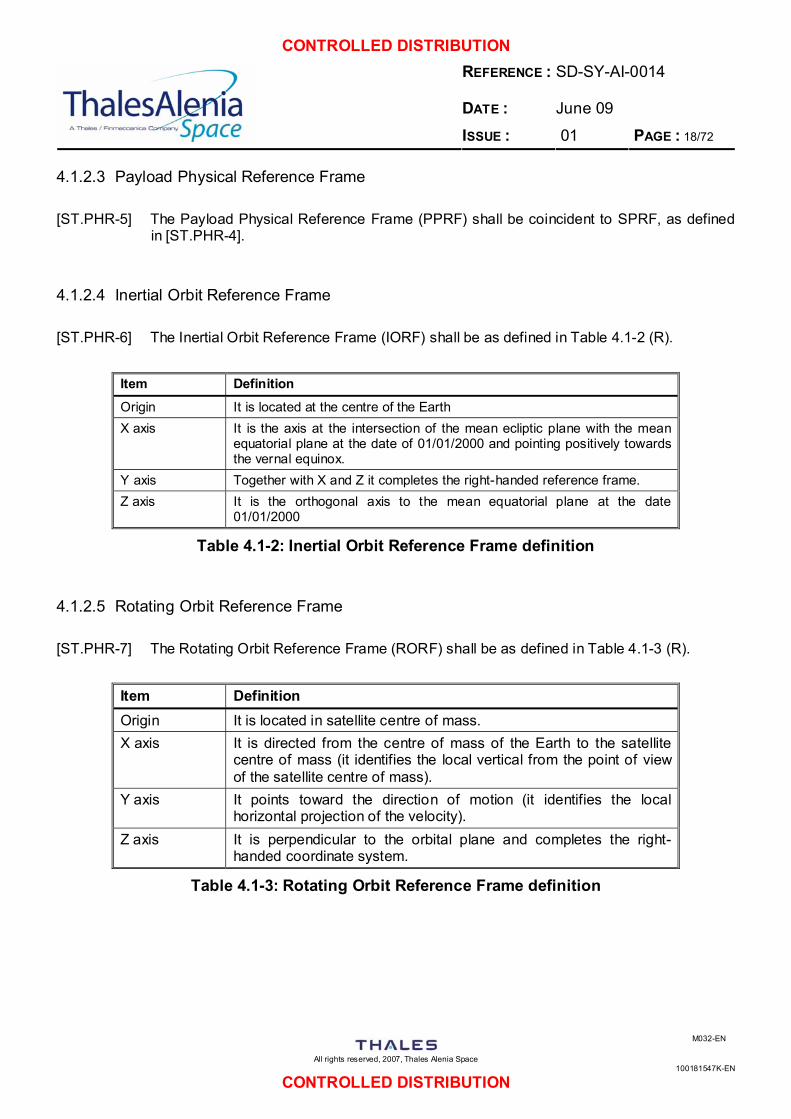
4.1.2.2 Satellite Physical Reference Frame
[ST.PHR-4] The Satellite Physical Reference Frame (SPRF) shall be as defined in Table 4.1-1 (R).
Item Definition
Origin It is located on the spinning axis and is nominally coincident with the satellite centre of mass (when PGB and proof masses are locked).
X axis It lies on the plane containing the origin and perpendicular to the spinning axis and passes through the median plane of the two pairs of capacitance plates in between the test masses. Together with Y axis positive verse is chosen to complete with Z axis a right-handed coordinate system
Y axis It lies on the plane containing the origin and perpendicular to the spinning axis and passes through the median plane of the two pairs of capacitance plates in between the test masses. Together with X axis positive verse is chosen to complete with Z axis a right-handed coordinate system
Z axis It corresponds to the central axis of the PGB connecting cylindrical tube (when the PGB is locked to the satellite) and is nominally the spinning axis of the satellite. Positive direction is the same of the angular rate vector.
Table 4.1-1: Satellite Physical Reference Frame definition
CONTROLLED DISTRIBUTION REFERENCE : DATE :
SD-SY-AI-0014 June 09
ISSUE : 01 PAGE : 18/72
All rights reserved, 2007, Thales Alenia Space
100181547K-EN
M032-EN
CONTROLLED DISTRIBUTION
4.1.2.3 Payload Physical Reference Frame
[ST.PHR-5] The Payload Physical Reference Frame (PPRF) shall be coincident to SPRF, as defined in [ST.PHR-4].
4.1.2.4 Inertial Orbit Reference Frame
[ST.PHR-6] The Inertial Orbit Reference Frame (IORF) shall be as defined in Table 4.1-2 (R).
Item Definition
Origin It is located at the centre of the Earth X axis It is the axis at the intersection of the mean ecliptic plane with the mean
equatorial plane at the date of 01/01/2000 and pointing positively towards the vernal equinox.
Y axis Together with X and Z it completes the right-handed reference frame. Z axis It is the orthogonal axis to the mean equatorial plane at the date
01/01/2000
Table 4.1-2: Inertial Orbit Reference Frame definition
4.1.2.5 Rotating Orbit Reference Frame
[ST.PHR-7] The Rotating Orbit Reference Frame (RORF) shall be as defined in Table 4.1-3 (R).
Item Definition Origin It is located in satellite centre of mass. X axis It is directed from the centre of mass of the Earth to the satellite
centre of mass (it identifies the local vertical from the point of view of the satellite centre of mass).
Y axis It points toward the direction of motion (it identifies the local horizontal projection of the velocity).
Z axis It is perpendicular to the orbital plane and completes the right-handed coordinate system.
Table 4.1-3: Rotating Orbit Reference Frame definition
CONTROLLED DISTRIBUTION REFERENCE : DATE :
SD-SY-AI-0014 June 09
ISSUE : 01 PAGE : 19/72
All rights reserved, 2007, Thales Alenia Space
100181547K-EN
M032-EN
CONTROLLED DISTRIBUTION
4.1.3 Spacecraft Resource Requirements
4.1.3.1 General
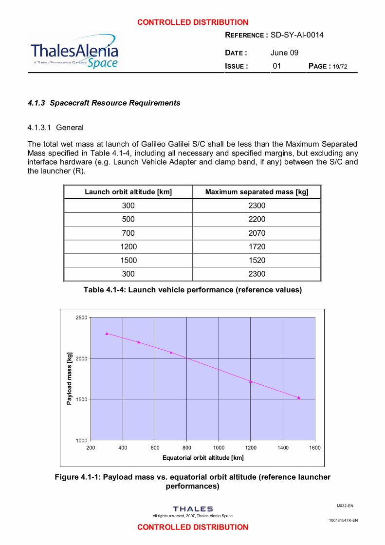
The total wet mass at launch of Galileo Galilei S/C shall be less than the Maximum Separated Mass specified in Table 4.1-4, including all necessary and specified margins, but excluding any interface hardware (e.g. Launch Vehicle Adapter and clamp band, if any) between the S/C and the launcher (R).
Launch orbit altitude [km] Maximum separated mass [kg]
300 2300
500 2200
700 2070
1200 1720
1500 1520
300 2300
Table 4.1-4: Launch vehicle performance (reference values)
1000
1500
2000
2500
200 400 600 800 1000 1200 1400 1600
Equatorial orbit altitude [km]
Payl
oad
mas
s [k
g]
Figure 4.1-1: Payload mass vs. equatorial orbit altitude (reference launcher
performances)
CONTROLLED DISTRIBUTION REFERENCE : DATE :
SD-SY-AI-0014 June 09
ISSUE : 01 PAGE : 20/72
All rights reserved, 2007, Thales Alenia Space
100181547K-EN
M032-EN
CONTROLLED DISTRIBUTION
[ST.PHR-8] The satellite, including propulsion and structure, shall be designed and sized for the Maximum Separated Mass at launch, including the system-level mass margin (R).
[ST.PHR-9] It shall be possible to increase the propellant load with a maximum of 20% of the nominal propellant load, or to the propellant tank load capacity (whichever is less), without requalification of the spacecraft (R).
[ST.PHR-10] The mission and spacecraft design shall be compatible with:
i. a launch period of 1 year, starting from the opening date specified in TBD. ii. a daily launch window of TBD s.
4.1.3.2 System Margin Requirements
[ST.PHR-11] The allocation of budgets for onboard resources shall provide the specified spare capacities for each subsystem and each payload. Detailed specifications of the required margins are provided in the various engineering disciplines chapters of the present document (R).
[ST.PHR-12] At the start of the Implementation Phase, the Total Mass at launch of the satellite shall include a system-level mass margin of at least 20% of the Nominal Mass at launch of the satellite (R).
[ST.PHR-13] The system-level mass margin shall:
i. be visible and traceable in the overall mass budget of the spacecraft, ii. not include any propellant residuals or unused fuel (R).
[ST.PHR-14] The Nominal Mass at launch shall not include the system-level mass margin, but shall include the design maturity mass margins to be applied at equipment level (R).
[ST.PHR-15] The Basic Mass at launch shall include neither the system-level mass margin, nor the design maturity mass margins to be applied at equipment level (R).
[ST.PHR-16] The design maturity margins given in Table 4.1-5 shall be applied to masses at equipment level (including the Launch Vehicle Adapter) (R).
CONTROLLED DISTRIBUTION REFERENCE : DATE :
SD-SY-AI-0014 June 09
ISSUE : 01 PAGE : 21/72
All rights reserved, 2007, Thales Alenia Space
100181547K-EN
M032-EN
CONTROLLED DISTRIBUTION
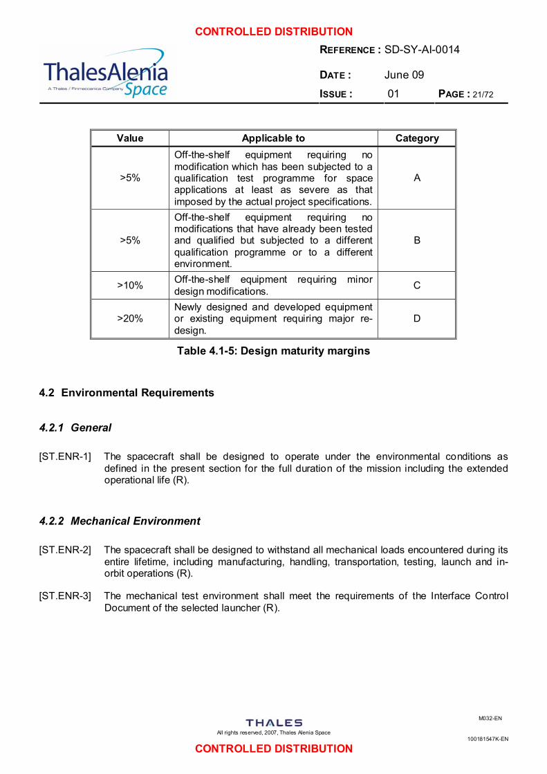
Value Applicable to Category
>5%
Off-the-shelf equipment requiring no modification which has been subjected to a qualification test programme for space applications at least as severe as that imposed by the actual project specifications.
A
>5%
Off-the-shelf equipment requiring no modifications that have already been tested and qualified but subjected to a different qualification programme or to a different environment.
B
>10% Off-the-shelf equipment requiring minor design modifications. C
>20% Newly designed and developed equipment or existing equipment requiring major re-design.
D
Table 4.1-5: Design maturity margins
4.2 Environmental Requirements
4.2.1 General
[ST.ENR-1] The spacecraft shall be designed to operate under the environmental conditions as defined in the present section for the full duration of the mission including the extended operational life (R).
4.2.2 Mechanical Environment
[ST.ENR-2] The spacecraft shall be designed to withstand all mechanical loads encountered during its entire lifetime, including manufacturing, handling, transportation, testing, launch and in-orbit operations (R).
[ST.ENR-3] The mechanical test environment shall meet the requirements of the Interface Control Document of the selected launcher (R).
CONTROLLED DISTRIBUTION REFERENCE : DATE :
SD-SY-AI-0014 June 09
ISSUE : 01 PAGE : 22/72
All rights reserved, 2007, Thales Alenia Space
100181547K-EN
M032-EN
CONTROLLED DISTRIBUTION
4.2.3 Thermal Environment
[ST.ENR-4] The spacecraft shall be able to meet the performance requirements specified in this Technical Specification under all thermal environments encountered during:
i. ground and pre-launch phases,
ii. ascent phase,
iii. in-flight operations from launcher separation until end of extended operational life,
with the worst combination of expected physical properties and operative conditions (R).
[ST.ENR-5] The following conditions shall be considered during ground and pre-launch phases:
i. integration and ground testing;
ii. storage, transport;
iii. spacecraft functional check-out and preparation at the launch site;
iv. pre-launch phase with the spacecraft encapsulated in the launch vehicle, waiting on launch pad (R).
[ST.ENR-6] The flight between fairing jettisoning and separation shall be considered during launch and ascent phases, for extreme cases of environmental conditions over the launch period (R).
[ST.ENR-7] The in-flight environment shall correspond to the existing conditions at the selected orbit for GG mission (R).
4.2.4 Cleanliness and Contamination
[ST.ENR-8] The spacecraft shall be integrated, tested, stored and transported in a clean environment of Class 100,000 of [SD 14] (R).
[ST.ENR-9] The spacecraft shall provide a centralised purging system available for instrument and other sensitive units (R).
[ST.ENR-10] Maximum level of chemical and particulate contamination shall not exceed TBD (R).
4.2.5 Radiation Environment
[ST.ENR-11] The effects of the varying flux of high energy particles can be separated at least into 3 classes:
• Radiation hazards: during its lifetime, the spacecraft and its components will receive an integrated dose that can degrade their performance and possibly cause failures.
• Radiation-induced background: radiation impinging on a detector or its associated
CONTROLLED DISTRIBUTION REFERENCE : DATE :
SD-SY-AI-0014 June 09
ISSUE : 01 PAGE : 23/72
All rights reserved, 2007, Thales Alenia Space
100181547K-EN
M032-EN
CONTROLLED DISTRIBUTION
electronics will produce an increase of the background noise.
• Single-Event Upsets (SEUs) and Latch-Ups (SELs): cosmic rays and heavy ion impacts can provoke SEUs and SELs which may disrupt the operation of sensitive electronics (D).
[ST.ENR-12] The spacecraft shall be able to withstand the effects of the varying flux of high energy particles encountered in its mission over the nominal operational life (R).
4.2.6 Micro-meteorite Environment
[ST.ENR-13] The spacecraft shall be able to withstand the micro-meteorite environment expected in the operative orbit conditions over the nominal operational life with a probability greater than 0.998 (R).
4.3 Mission Requirements
4.3.1 General
[ST.MIR-1] The spacecraft shall provide visibility of its internal status and configuration to the Ground Segment in accordance with the level of detail and the time delays specified for all nominal and foreseeable contingency operations, including subsequent diagnostic activities (R). Note: Foreseeable contingency operations are derived during the failure analysis performed in the mission development process (e.g. the Failure Modes, Effects and Criticality Analysis).
[ST.MIR-2] The control functions (telecommands) provided at each level of the design hierarchy shall be capable of achieving the mission objectives under all specified circumstances (R). Note: This can include the use of redundant equipment.
[ST.MIR-3] The spacecraft shall not require any TM monitoring or TC commanding from Ground during the launch phase (R).
4.3.2 Launch and Early Orbit Phase
[ST.MIR-4] The mission and spacecraft design shall be compatible with a launch period duration as defined in GG MRD i.e. [AD 2] (R).
CONTROLLED DISTRIBUTION REFERENCE : DATE :
SD-SY-AI-0014 June 09
ISSUE : 01 PAGE : 24/72
All rights reserved, 2007, Thales Alenia Space
100181547K-EN
M032-EN
CONTROLLED DISTRIBUTION
4.3.3 Commissioning Phase
[ST.MIR-5] At separation from launcher the spacecraft shall be released in a spin-stabilised attitude with a spin rate of TBD Hz (R).
[ST.MIR-6] The nominal spin rate shall be achieved during the Commissioning Phase by means of the spacecraft’s own propulsion (R).
[ST.MIR-7] Each manoeuvre shall not affect or limit the maintenance of satellite spin-stabilised attitude at the nominal spin rate (R).
[ST.MIR-8] During the Commissioning Phase the spacecraft shall be capable of acquiring and maintaining any attitude required by the sequence of mission operations, such as commissioning of the spacecraft systems, early validation of specific mission modes, tracking for orbit determination, early trajectory maintenance and correction manoeuvres, health checks, etc. (R).
[ST.MIR-9] The spacecraft shall support an initial checkout of payload equipments during the Commissioning Phase (R).
[ST.MIR-10] All operational RF links shall be tested as part of the Commissioning Phase (R).
4.3.4 Orbit Phase
[ST.MIR-11] The GG spacecraft nominal attitude in Earth orbit shall be spin-axis stabilised with +ZGG perpendicularly directed with reference to Earth equatorial plane (R).
[ST.MIR-12] In nominal attitude the spacecraft shall maintain the nominal spin rate of 1 Hz. (R).
[ST.MIR-13] Drag compensation manoeuvres shall be performed by the appositely designed and sized drag-free attitude control subsystem with the use of appropriate thrust equipment (i.e. non chemical thrusters if required) without affecting the maintenance of spin rate at the nominal value (R).
[ST.MIR-14] In nominal orbit the spacecraft shall be able to perform the attitude control manoeuvres and off-loadings necessary during the specified lifetime. Availability of the necessary resources (e.g. propellant) shall be taken into account in the overall resource budgets (R).
4.3.5 Disposal Phase
[ST.MIR-15] No specific requirement is issued for disposal phase. It is expected that at the end of operational lifetime and the scientific utility of the spacecraft, appropriate manoeuvres should facilitate the orbital decay in the frame of common effort to limit the quantity of debris in orbit (G).
CONTROLLED DISTRIBUTION REFERENCE : DATE :
SD-SY-AI-0014 June 09
ISSUE : 01 PAGE : 25/72
All rights reserved, 2007, Thales Alenia Space
100181547K-EN
M032-EN
CONTROLLED DISTRIBUTION
4.4 Experiment Requirements
[ST.EXR-1] GG Experiment requirements shall be as defined in Experiment Concept and Requirements Document i.e. [AD 3] (R).
4.5 Spacecraft Requirements
4.5.1 General Requirements
4.5.1.1 Overall Design Approach Requirements
[ST.SCR-1] The design margin philosophy shall comply with [SD 2] (R).
[ST.SCR-2] As general concept the spacecraft design shall be compliant to the ASI cost policy of a small satellite (R).
[ST.SCR-3] Launch mass of GG satellite, including launcher adapter, shall not exceed 500 kg (R).
[ST.SCR-4] All radiation sensitive units shall be selected and sized from launch until the end of the nominal mission (R).
[ST.SCR-5] All radiation sensitive units shall be selected and sized from launch until the end of the extended mission. Margins are not applied to the extended lifetime (G).
4.5.1.2 Lifetime Requirements
[ST.SCR-6] The spacecraft shall have a nominal lifetime of 1 year in flight, from end of commissioning phase to end of nominal operational life (R).
[ST.SCR-7] The spacecraft shall have an extended lifetime of 2 years in flight, from end of commissioning phase to end of nominal operational life (G).
[ST.SCR-8] All spacecraft consumables shall be sized to allow for the total operational life, from launch to end of nominal operational life (R).
[ST.SCR-9] All spacecraft consumables shall be sized to allow for the total operational life, from launch to end of extended operational life (G).
[ST.SCR-10] The capability shall be provided to determine at any point in the mission the remaining onboard resources that impact on mission lifetime. This shall be done by onboard logging and storing in non-volatile memory of the required parameters (R).
[ST.SCR-11] Where the design margin on nominal lifetime is not identified, or where the design margin is required for demonstration or resistance to failure modes, a factor of 2 times the nominal lifetime shall be included as a minimum (R).
CONTROLLED DISTRIBUTION REFERENCE : DATE :
SD-SY-AI-0014 June 09
ISSUE : 01 PAGE : 26/72
All rights reserved, 2007, Thales Alenia Space
100181547K-EN
M032-EN
CONTROLLED DISTRIBUTION
4.5.1.3 Pointing and Stability Requirements
Definitions [ST.SCR-12] The pointing terminology shall be in accordance with the ESA Pointing Error Handbook
(R).
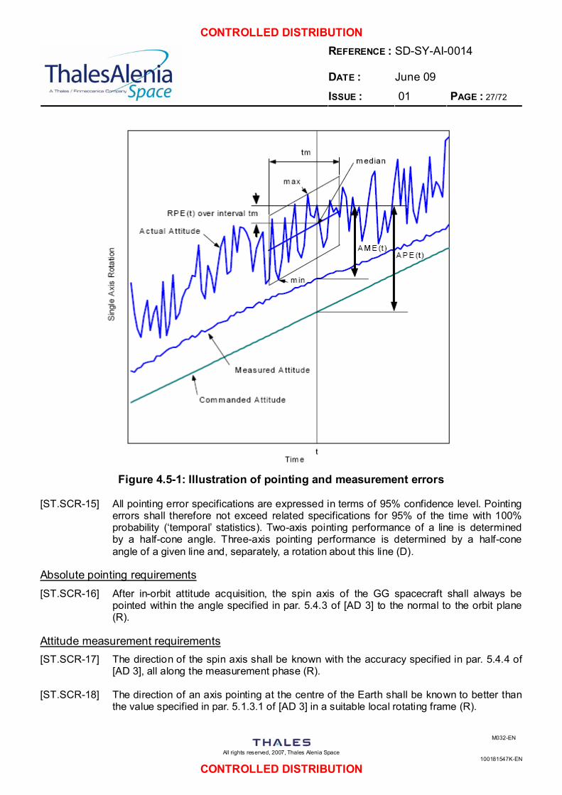
[ST.SCR-13] In accordance with ECSS-E-ST-60-10C [SD 12], the following pointing terminology is used in this document:
i. Absolute Pointing Error (APE): angular separation between the actual and the commanded generalised pointing vectors of the spacecraft.
ii. Relative Pointing Error (RPE): difference between the instantaneous APE and the median APE defined over a time interval containing the reference time instant. The median APE minimises the absolute separation between median and actual generalised pointing vectors over time interval. The RPE is also known as pointing stability.
iii. Absolute Measurement Error (AME): angular separation between the actual and measured generalised pointing vectors of the spacecraft (D).
[ST.SCR-14] The APE and RPE pointing errors are real-time errors, whereas the AME measurement error refers to the reconstructed attitude that is obtained a posteriori. These errors are illustrated in Figure 4.5-1 (D).
CONTROLLED DISTRIBUTION REFERENCE : DATE :
SD-SY-AI-0014 June 09
ISSUE : 01 PAGE : 27/72
All rights reserved, 2007, Thales Alenia Space
100181547K-EN
M032-EN
CONTROLLED DISTRIBUTION
Figure 4.5-1: Illustration of pointing and measurement errors
[ST.SCR-15] All pointing error specifications are expressed in terms of 95% confidence level. Pointing errors shall therefore not exceed related specifications for 95% of the time with 100% probability (‘temporal’ statistics). Two-axis pointing performance of a line is determined by a half-cone angle. Three-axis pointing performance is determined by a half-cone angle of a given line and, separately, a rotation about this line (D).
Absolute pointing requirements [ST.SCR-16] After in-orbit attitude acquisition, the spin axis of the GG spacecraft shall always be
pointed within the angle specified in par. 5.4.3 of [AD 3] to the normal to the orbit plane (R).
Attitude measurement requirements [ST.SCR-17] The direction of the spin axis shall be known with the accuracy specified in par. 5.4.4 of
[AD 3], all along the measurement phase (R).
[ST.SCR-18] The direction of an axis pointing at the centre of the Earth shall be known to better than the value specified in par. 5.1.3.1 of [AD 3] in a suitable local rotating frame (R).
CONTROLLED DISTRIBUTION REFERENCE : DATE :
SD-SY-AI-0014 June 09
ISSUE : 01 PAGE : 28/72
All rights reserved, 2007, Thales Alenia Space
100181547K-EN
M032-EN
CONTROLLED DISTRIBUTION
4.5.1.4 Payload Interface Requirements
[ST.SCR-19] The GG spacecraft design shall be done with reference to the scientific experiment specific needs (R).
[ST.SCR-20] The spacecraft shall provide all necessary resources (volume, mass, power, data, pointing, alignment, location with respect to CoG, thermal control, heat rejection, etc.) to the payload in accordance with the requirements (R).
[ST.SCR-21] The spacecraft shall provide the following thermal performances to scientific payload:
• test mass mean temperature stability better than 0.1°K/day
• test mass axial temperature gradient < 2°K/m axial.
• test mass azimuth temperature gradient expected to be negligible because of high spin rate (R).
[ST.SCR-22] The payload shall be supplied with 28V regulated power. The regulation accuracy shall be +1% / -3% at payload input (R).
4.5.2 Command & Control Requirements
4.5.2.1 General Requirements
[ST.SCR-23] A Command & Control Function shall be provided, to support:
• Spacecraft control
• Management of Spacecraft Modes
• Management of System Autonomy, FDIR (Redundancy Management) and Safe Mode
• Ground Segment interface via TM/TC links by means of the TT&C
• Attitude & Orbit Control by means of the Attitude & Orbit Control and Propulsion resources
• Electrical Power functions and control of the power resources
• Control of the thermal resources
• Payload functional interface and common services (R).
[ST.SCR-24] The spacecraft shall be compatible with the following standards:
• ECSS-E-50-12 SpaceWire - Links, nodes, routers and networks
• ECSS-E-50-14 Spacecraft onboard interfaces: Discrete interfaces
• ECSS-E-50-05 Radio Frequency and Modulation
• CCSDS 121.0-B-1 Lossless Compression
CONTROLLED DISTRIBUTION REFERENCE : DATE :
SD-SY-AI-0014 June 09
ISSUE : 01 PAGE : 29/72
All rights reserved, 2007, Thales Alenia Space
100181547K-EN
M032-EN
CONTROLLED DISTRIBUTION
• CCSDS 131.0-B-1 TM Synchronization and Channel Coding. Blue Book.
• CCSDS 132.0-B-1 TM Space Data Link Protocol. Blue Book.
• CCSDS 133.0-B-1 Space Packet Protocol. Blue Book.
• CCSDS 231.0-B-1 TC Synchronization and Channel Coding. Blue Book.
• CCSDS 232.0-B-1 TC Space Data Link Protocol. Blue Book. Issue 1.
• MIL-1553-B-Notice 4 Onboard Interfaces
• CCSDS 301.0-B-3 Time Code Formats (R).
[ST.SCR-25] The Command & Control Function shall monitor and control essential equipment configuration, including its own processor, by means of independent hardware, without any software intervention (R).
[ST.SCR-26] The Command & Control Function interfaces (transponder, platform equipment, instrument interfaces) shall be fully redundant (inside or outside the unit) including cross-strapping to improve reliability (R).
4.5.2.2 Spacecraft Control Requirements
[ST.SCR-27] During all mission phases there shall be no requirement for the Ground to send telecommands in nominal or contingency cases with a response time of less than TBD hours (R).
[ST.SCR-28] Situations in which the Ground is required to react within TBD shall be unambiguously recognizable in the available telemetry, without the need for complex processing (R).
[ST.SCR-29] Autonomous recovery to normal operations after a recoverable failure shall be attempted except in clear cases when spacecraft safety is jeopardised (R). Note: A recoverable failure is defined as a failure that can be isolated unambiguously and that allows a redundancy to be used.
[ST.SCR-30] The spacecraft shall always be able to receive and process a continuous uplink of telecommand packets at the highest nominal uplink rate (R).
Note: The spacecraft design shall not impose any artificial slowing down of the command rate below what is achievable with the RF uplink rate.
[ST.SCR-31] HK Telemetry shall be continuously generated and recorded in all modes of operations, including Safe Mode (R).
4.5.2.3 Spacecraft Modes
[ST.SCR-32] For configuration management purposes, the spacecraft shall be able to support at least the following modes:
• Pre-Launch Modes for configuration of the spacecraft for launch and ground testing;
• Operational Modes ensuring the generation of mission products;
• Safe Modes ensuring safety of all spacecraft subsystems and payloads (R).
CONTROLLED DISTRIBUTION REFERENCE : DATE :
SD-SY-AI-0014 June 09
ISSUE : 01 PAGE : 30/72
All rights reserved, 2007, Thales Alenia Space
100181547K-EN
M032-EN
CONTROLLED DISTRIBUTION
[ST.SCR-33] The modes of the spacecraft and its payload, subsystems and units shall be clearly identified in terms of both hardware and software (R).
[ST.SCR-34] The telemetry shall provide unambiguous identification of the modes and mode transitions (R).
[ST.SCR-35] The spacecraft shall be able to support the modes based on any compatible combination of onboard main and redundant units (R).
[ST.SCR-36] Initialisation of a mode (at spacecraft, subsystem or unit level) shall include configuration of the necessary hardware (e.g. sensors, actuators), activation of a default periodic telemetry configuration, and all the automatic processes (e.g. automatic control of attitude slews) required to achieve the objective of the mode (R).
[ST.SCR-37] The spacecraft shall autonomously prevent execution of forbidden mode transitions. It shall be possible for Ground to overwrite the enable/disable status of any defined pair of autonomous mode transitions (R).
[ST.SCR-38] It shall be possible to command the spacecraft or any subsystem or instrument into each of the predefined spacecraft modes by means of a single telecommand function (R).
[ST.SCR-39] In all modes, it shall be possible to command the spacecraft via an LGA in emergency cases (R).
4.5.2.4 Autonomy, FDIR (Redundancy Management) and Safe Mode
General Autonomy and FDIR [ST.SCR-40] Autonomy shall be divided into two separate functions:
• Normal Mission Autonomy (NMA)
• Failure Detection, Isolation and Recovery (FDIR) (R).
[ST.SCR-41] There shall be two separate levels of FDIR: Redundancy Management FDIR level and System Safety level (Safe Mode) (R).
[ST.SCR-42] The two levels of FDIR shall not interfere with each other (R).
[ST.SCR-43] FDIR shall not trigger on one sample of a parameter. Possibly redundant readings shall be verified. As a minimum, contiguous samples shall be used (R).
[ST.SCR-44] FDIR limits shall be set as wide as possible with regard to mission safety, to avoid triggering for false reasons (R).
[ST.SCR-45] The FDIR functions implemented onboard should be intrinsically fail-safe (R).
[ST.SCR-46] For clearly identified critical mission phases fail-operational shall be implemented (R).
[ST.SCR-47] Hot redundancy shall be provided for functions which are essential for a continuous, uninterrupted operation needed for mission success (R).
CONTROLLED DISTRIBUTION REFERENCE : DATE :
SD-SY-AI-0014 June 09
ISSUE : 01 PAGE : 31/72
All rights reserved, 2007, Thales Alenia Space
100181547K-EN
M032-EN
CONTROLLED DISTRIBUTION
Autonomy Requirements [ST.SCR-48] Spacecraft Autonomy shall be limited to the minimum level required to ensure spacecraft
safety and achievement of all mission goals (R).
[ST.SCR-49] The Autonomy shall be implemented using deterministic algorithmic techniques (R).
[ST.SCR-50] All data used for autonomy shall be contained in a common data pool for each processor (R).
[ST.SCR-51] It shall be possible for a process to wait on update of a parameter in the data pool (R).
[ST.SCR-52] It shall be possible to write into any data pool area via a dedicated telecommand (R).
[ST.SCR-53] Telemetry issued as the result of an autonomously issued telecommand shall be routed to the autonomous process that generated the telecommand, as well as to the Ground (R).
[ST.SCR-54] All parameters used for autonomous operations (e.g. thresholds for limit checking or thresholds and biases for attitude control), including fault management, orbit and attitude control, etc., shall be updatable by telecommand and available in telemetry, without the need for low level OBSW patch TC and dump TM (R).
[ST.SCR-55] All housekeeping telemetry generated by all the spacecraft subsystems shall be stored in a central data pool and made available to all onboard functions (R). Note 1: This includes packet and non-packet users. Note 2: The set of TM data - either internal to the Command & Control Function or collected from external units, subsystems or payload instruments - which is available to the central autonomy function will be called hereafter “Central Data Pool”.
[ST.SCR-56] Event parameters extracted from event packets as defined in Event Monitoring Service shall be stored in the Central Data Pool and made available to all onboard functions (R).
[ST.SCR-57] The spacecraft shall provide mechanisms to avoid or recover from any conflict that can arise from the execution of onboard autonomous actions and Ground scheduled commands (R).
Note: Examples are the parallel execution of routine procedures and event-driven procedures.
[ST.SCR-58] Autonomy used for normal operations shall be based on the use of MTL, OBCPs and High Level Functions (R).
[ST.SCR-59] Control of the autonomy shall be by high-level commands (R). Note: A high-level command can be "Configure unit for XXX mode".
[ST.SCR-60] Monitoring of all the autonomy shall be by defined telemetry packets. At no time shall the Ground have to request memory dumps for information (R).
Redundancy Management FDIR [ST.SCR-61] Whenever reasonably possible, the redundancy FDIR shall attempt the continuation of
mission products generation (G).
CONTROLLED DISTRIBUTION REFERENCE : DATE :
SD-SY-AI-0014 June 09
ISSUE : 01 PAGE : 32/72
All rights reserved, 2007, Thales Alenia Space
100181547K-EN
M032-EN
CONTROLLED DISTRIBUTION
[ST.SCR-62] Any potential conflict between failure recovery activities and nominally ongoing onboard commanding activities shall be identified and managed (R). Note: This can imply suspending the onboard operations schedule and currently active onboard operations procedures.
[ST.SCR-63] For failures whose resolution does not imply safeguarding of system functions, hierarchical steps shall be applied (e.g. protocol-level retries or onboard control procedures) before removal of the failed unit from operational configuration (R).
Note: The hierarchical steps can include:
• command retries and telemetry read back;
• appropriate equipment switching or software re-initialisation, i.e. the selection of redundant equipment by telecommand or by OBCPs, including functional verification;
• application of delay times before switching off the failed equipment.
[ST.SCR-64] The management of anomalies within a unit, subsystem or instrument shall be handled in a hierarchical manner, such that resolution is sought on the lowest possible level. Scientific operations shall be suspended whenever an anomaly is detected (R).
[ST.SCR-65] All intelligent units and instruments shall perform regular self-checks, and shall report them (R). Note: Intelligent units are those able to generate TM packets, and to process TC packets.
[ST.SCR-66] A higher level autonomous function shall check these reports and instigate recovery actions if needed (R)
[ST.SCR-67] The fault management functions at all levels shall be able to carry out consistency verification checks on redundant sensor readings whenever redundancy is available, before starting the recovery actions (R).
[ST.SCR-68] The FDIR functions shall not be based on processing of an input currently disabled (R).
[ST.SCR-69] The spacecraft shall manage the isolation of failed/suspected units and the switching where possible to redundant units to avoid failure propagation (R).
[ST.SCR-70] For failures whose resolution implies safeguarding of system functions, the offending unit, subsystem or function shall be disabled or switched off (R).
[ST.SCR-71] A failure in the performance of an autonomous recovery action shall be followed by an action to ensure the safety of the spacecraft, subsystem or payload (R). Note: In some cases, predefined retries are implemented in the system (e.g. for protocol handling).
[ST.SCR-72] The responses of the redundancy level FDIR to the triggering of a failure monitor shall be deterministic and repeatable (R).
[ST.SCR-73] The spacecraft shall maintain a list of available, suspected and failed hardware units. This information shall be updatable by dedicated telecommand and available in telemetry (R).
CONTROLLED DISTRIBUTION REFERENCE : DATE :
SD-SY-AI-0014 June 09
ISSUE : 01 PAGE : 33/72
All rights reserved, 2007, Thales Alenia Space
100181547K-EN
M032-EN
CONTROLLED DISTRIBUTION
[ST.SCR-74] Failures that cannot be handled at a given level shall be handed over to the next higher operational instance, the highest one being the Ground (R).
[ST.SCR-75] Where possible, failure recovery actions shall first attempt a software reboot before considering a hardware reconfiguration of the affected units (G).
[ST.SCR-76] If an onboard processor is switched from a main to a redundant unit (or vice versa), the switchover shall be such that operations can continue safely (R). Note: This implies that:
• either the operational context need not be reloaded from Ground, or
• the new processor can be loaded with a safe default context before the switchover.
[ST.SCR-77] The activation of a redundant unit or functional path shall not require a change of the configuration or operational status of another unit (R).
[ST.SCR-78] Anomalies and actions taken to recover from them shall be reported in event driven packets (R).
[ST.SCR-79] It shall be possible to reconstruct from telemetry the conditions leading to the generation of an event (R).
[ST.SCR-80] The fault management functions at all levels shall be able to access lower-level telemetry data produced by the subsystems and instruments, with the exception of science data. This includes in particular non-periodic event packets which can be used to trigger recovery actions at system or subsystem level, as a result of an anomaly occurred (and detected) in another subsystem (R).
[ST.SCR-81] Failure detection algorithms shall avoid continuous production of the same anomaly report packet, if the same failure is detected within a number of monitoring cycles which is to be defined for each failure case (R).
[ST.SCR-82] Failure detection algorithms shall start generation of all support telemetry packets considered necessary for the Ground analysis of the failure (R).
[ST.SCR-83] It shall be possible for the Ground to enable/disable each individual fault management function (R).
[ST.SCR-84] For control of all FDIR Surveillances (i.e. low-level parameter monitoring functions implemented in the individual onboard software packages for health monitoring at subsystem/unit level) dedicated telecommands shall be available as follows:
• enable/disable single surveillances.
Note: Surveillances enable/disable status may be also controlled by the onboard software at unit switch-on/mode transition. The surveillance shall actually be enabled only if enabled both by ground and the onboard software.
• enable/disable recovery action of single surveillances.
• enable/ disable all surveillances.
• modify the surveillance definition (thresholds, filters) (R).
CONTROLLED DISTRIBUTION REFERENCE : DATE :
SD-SY-AI-0014 June 09
ISSUE : 01 PAGE : 34/72
All rights reserved, 2007, Thales Alenia Space
100181547K-EN
M032-EN
CONTROLLED DISTRIBUTION
Note: Ground does not request to update the parameters being monitored by the surveillance, nor the recovery action.
[ST.SCR-85] It shall be possible to request a report of all defined surveillances, giving the list of surveillances including their complete definition (surveillance ID, parameter being monitored, thresholds applied filters applied) (R).
[ST.SCR-86] The following FDIR surveillance information shall be available in housekeeping telemetry for each defined surveillance:
• enable/disable status by Ground;
• overall enable/disable status;
• enable/disable status of recovery action.
Onboard Reconfiguration Handling [ST.SCR-87] This section covers spacecraft reconfigurations that can be carried out by Ground direct
command, NMA or FDIR (D).
[ST.SCR-88] Definitions:
• Main: defines the main or prime hardware unit of a redundant subsystem.
• Redundant: defines the redundant or backup hardware unit of a redundant subsystem.
• Operational: defines the currently selected hardware unit that is in the onboard control loop for mission operations.
• Spare: defines the unit that can be selected as operational after a subsystem or system reconfiguration (D). Note: The spare unit can be the same physical unit as the operational one after an onboard failure or reconfiguration.
[ST.SCR-89] All onboard reconfigurations shall end with an unambiguously known and observable state of all involved elements (hardware and software) (R).
[ST.SCR-90] The maximum duration of an onboard reconfiguration shall be deterministic (R).
[ST.SCR-91] Telemetry shall be available for the Ground to monitor all stages of an onboard reconfiguration (R).
[ST.SCR-92] The reconfiguration of onboard units or the switching between onboard functions shall not affect the status, configuration, or the proper operation of any other unrelated unit or function (R).
[ST.SCR-93] Telemetry indicating the cause of an onboard reconfiguration shall be available to the Ground after the completion of the reconfiguration (R).
[ST.SCR-94] The capability shall be provided to pre-configure selected units into predefined configurations prior to selection as operational (R).
CONTROLLED DISTRIBUTION REFERENCE : DATE :
SD-SY-AI-0014 June 09
ISSUE : 01 PAGE : 35/72
All rights reserved, 2007, Thales Alenia Space
100181547K-EN
M032-EN
CONTROLLED DISTRIBUTION
[ST.SCR-95] With the exception of high-priority commands initiated by Ground, it shall be possible to buffer onboard all spacecraft configuration change telecommands that are defined to be critical, in such a way that all parameters defining the new configuration can be inspected by the Ground, via telemetry, before executing the change onboard (R).
[ST.SCR-96] The capability shall be provided to trigger any onboard reconfiguration activities that put the spacecraft into a predefined safe state autonomously, and by Ground commanding (R).
[ST.SCR-97] At power-up, restart and upon recovery from any power loss, the spacecraft electrical configuration (including all subsystems, units and instruments) shall be set into a known deterministic and reproducible state. This configuration shall not depend on the speed of the level of power becoming available. This requirement shall be verified by analysis and worst case system-level end-to-end testing, using a representative solar array electrical power simulator instead of the solar array (R).
[ST.SCR-98] The capability shall be provided for the Ground to allocate which of the redundant units are included in the nominal chain and which in the redundant chain (R). Note: This enables redundancy to be restored without reconfiguring the onboard hardware, and also enables a failed unit to be removed from both the nominal and redundant chains while maintaining the rest of the redundancy of the chain. This new configuration will be applied after a processor restart.
[ST.SCR-99] All defined combinations of main and redundant equipment shall exhibit the same operational characteristics (R).
Note: This does not include any reduced redundancy that exists following a failure. Any selection of main or redundant equipment shall be reversible by the Ground, even if it is to revert to a unit declared to be previously in failure state.
[ST.SCR-100] Redundancy switching at unit level shall not require changes in telecommands directed to the operational unit (R).
Note: This allows previously loaded commands (e.g. mission timeline, OBCPs) to address the current operational unit.
[ST.SCR-101] The onboard fault management shall avoid continuous toggling of the configuration of a unit between the main and the redundant element (R).
Safe Mode [ST.SCR-102] The number of different Safe Modes shall be minimised by spacecraft design (R).
[ST.SCR-103] Entry into Safe Mode shall be the result of the crossing of clear spacecraft-level safety critical dead bands, or of a clear case in which the low-level FDIR recovery was not possible (R).
[ST.SCR-104] The spacecraft shall not enter Safe Mode if no vital or spacecraft-level safety critical functions are affected (R). Note: In particular, this implies a robustness of the implementation of the hierarchical FDIR to cope with minor errors (e.g. operational errors resulting from a single telecommand issued in the wrong context) and with recoverable ones (e.g. single unit redundancy switching).
CONTROLLED DISTRIBUTION REFERENCE : DATE :
SD-SY-AI-0014 June 09
ISSUE : 01 PAGE : 36/72
All rights reserved, 2007, Thales Alenia Space
100181547K-EN
M032-EN
CONTROLLED DISTRIBUTION
[ST.SCR-105] It shall be possible to enable/disable autonomous entry, and to force entry into Safe Mode by telecommand. Autonomous entry shall be enabled by default (R).
[ST.SCR-106] No nominal operation shall require inhibition of the Safe Mode nor a forced entry into Safe Mode (R).
[ST.SCR-107] The transition to Safe Mode, once started, shall not be interruptible (R).
[ST.SCR-108] Safe Mode shall, in each mission phase, guarantee the achievement of an indefinitely stable safe condition from any possible initial condition caused by any single failure (however improbable) that triggers a safety monitor (e.g. worst case possible dynamic conditions, worst case timings) (R).
[ST.SCR-109] The Safe Mode final condition shall be defined such that:
uninterrupted power supply, as required for spacecraft safety, is provided;
a thermally safe attitude is maintained;
communications with the Ground are guaranteed (R).
[ST.SCR-110] The Safe Mode shall include all payload reconfiguration activities necessary to put the payload in a safe and recoverable mode, in particular reacting to changes of attitude, and at the same time minimising the power demand from the instruments (R).
[ST.SCR-111] No mission products need to be generated in Safe Mode (R).
[ST.SCR-112] In case of a Safe Mode, the spacecraft shall start generating a minimum set of telemetry packets which allow unambiguous and rapid identification of the Safe Mode. The reason for the triggering of the Safe Mode and the history of the defined events occurred before and after the detection of the failure condition shall also be accessible in telemetry, either directly or stored in memory areas that can be later dumped and reset by the Ground (R).
[ST.SCR-113] The spacecraft shall have the capability to re-establish the Ground communications link in case a spin-axis controlled Earth acquisition cannot be performed.
[ST.SCR-114] Essential onboard autonomous functions, compatible with the survival requirement of 14 days in cruise without Ground contact, shall be available in Safe Mode (R).
[ST.SCR-115] The consumption of spacecraft consumables shall be minimised while in Safe Mode (R).
[ST.SCR-116] In Safe Mode, control of the spacecraft shall be nominally transferred to the wheels as soon as possible (R).
[ST.SCR-117] The spacecraft state variables shall be properly reinitialised for execution of the Safe Mode, and no residual values coming from previous spacecraft modes shall endanger the Safe Mode execution or recovery to Normal Mode (R).
[ST.SCR-118] Recovery from Safe Mode shall be undertaken under Ground control (R).
[ST.SCR-119] No residual values of spacecraft state variables after entry and execution of Safe Mode shall remain in the recovered Normal Mode (R).
CONTROLLED DISTRIBUTION REFERENCE : DATE :
SD-SY-AI-0014 June 09
ISSUE : 01 PAGE : 37/72
All rights reserved, 2007, Thales Alenia Space
100181547K-EN
M032-EN
CONTROLLED DISTRIBUTION
4.5.2.5 General Functional Requirements
Telecommands [ST.SCR-120] Telecommands shall be available to command all onboard equipment and functions
under all nominal and foreseen contingency conditions (R). Note: This implies the provision of a high-priority command to re-establish command processing in the event of processor failure.
[ST.SCR-121] No single command function executed at the wrong time or in the wrong configuration shall lead to the loss of mission. Execution of hazardous functions shall be implemented by means of two independent telecommands (R).
Note: Hazardous functions are those which, when executed at the incorrect time, could cause mission degradation or damage to equipment, facilities or personnel.
[ST.SCR-122] Execution of identified vital functions (shall be implemented by 2 independently routed (nominal and a redundant) telecommands (R). Note: Vital functions are those which, if not executed, could cause mission degradation.
[ST.SCR-123] A telecommand packet shall contain one and only one telecommand function. Note: A telecommand function is an operationally self-contained control action. A telecommand function may comprise or invoke one or more low-level control actions.
[ST.SCR-124] It shall be possible to command all onboard devices individually from the Ground (R).
[ST.SCR-125] A telecommand that does not conform to the packet telecommand standard and/or is not recognised as a valid GG telecommand shall be rejected at the earliest possible stage in the onboard acceptance and execution process (R).
[ST.SCR-126] The onboard reception, processing and execution of telecommands to a unit shall not affect the performance of other ongoing processes (R).
[ST.SCR-127] Changes to onboard data or software parameters shall be implemented via a dedicated telecommand and not via a multipurpose software load telecommand (R).
[ST.SCR-128] Readouts of loaded onboard data or software parameters shall be requested via a dedicated telecommand (R).
[ST.SCR-129] In order to be able to unambiguously identify the source of a telecommand (e.g. the Ground or a given onboard application process), the source shall be explicitly indicated within the telecommand itself (R). Note: This shall be done by use of the source part of the sequence count and the source ID in the data files header.
[ST.SCR-130] The capability of directly configuring the onboard computers without onboard software intervention shall be provided (R)
Telemetry [ST.SCR-131] Telemetry data shall be provided on request to the Ground such that complete and
unambiguous assessment of the spacecraft status and performance is possible without the need for reference to the telecommand history (R).
CONTROLLED DISTRIBUTION REFERENCE : DATE :
SD-SY-AI-0014 June 09
ISSUE : 01 PAGE : 38/72
All rights reserved, 2007, Thales Alenia Space
100181547K-EN
M032-EN
CONTROLLED DISTRIBUTION
[ST.SCR-132] Telemetry shall be provided to allow adequate and unambiguous verification of acceptance, progress (where applicable) and execution of all telecommands sent from any source (sent from Ground for immediate, delayed or time-tagged execution, and sent from onboard applications) (R).
Note: The level of verification will be specified by the command acknowledgment field.
[ST.SCR-133] Telemetry shall always be provided to unambiguously identify the conditions required for execution of all possible configuration dependent telecommands (R).
Note: A configuration dependent telecommand is a telecommand, which shall only be executed if a particular subsystem or instrument condition is satisfied (R).
[ST.SCR-134] Status information in telemetry shall always be provided from direct measurements from operating units rather than from secondary effects. This is in particular essential for the status of all onboard relays (R).
Note: This includes the observability of the complete status of the spacecraft from the telemetry without the need for reference to the telecommand history or any record of onboard autonomous actions.
Timing [ST.SCR-135] All mission critical functions shall be observable by at least 2 independently obtained
measurements (R). Note: A mission critical action at the wrong time or in the wrong configuration could cause the loss of spacecraft, or the degradation of the mission.
[ST.SCR-136] All inputs to onboard autonomous processes, in particular OBCPs, shall be accessible to the Ground via telemetry (R).
[ST.SCR-137] Information to indicate all actions of operational significance taken by onboard software shall be available in telemetry (R).
[ST.SCR-138] Software status telemetry shall include all commandable parameters such as monitoring and control thresholds, software tables, flags, global variables used by OBCPs, etc. It is acceptable to access all parameters via a single telecommand of each type using unique parameter IDs to access the parameters. The telemetry packet shall include the parameter ID as the first parameter after the data field header (R).
[ST.SCR-139] The values of telemetry parameters shall be self-contained (R). Note: This means that only actual values or actual status shall be downlinked, and not changes (or delta values) since the last readout.
[ST.SCR-140] The value of a telemetry parameter shall be transmitted in contiguous bits within one packet (R).
[ST.SCR-141] All telemetry packets generated onboard and defined for transmission to the Ground shall also be stored onboard until deleted by ground, regardless of the VC used for transmission (R).
[ST.SCR-142] Any packet carrying measurement and performance information for a unit shall also contain health monitoring data for that unit (R).
CONTROLLED DISTRIBUTION REFERENCE : DATE :
SD-SY-AI-0014 June 09
ISSUE : 01 PAGE : 39/72
All rights reserved, 2007, Thales Alenia Space
100181547K-EN
M032-EN
CONTROLLED DISTRIBUTION
[ST.SCR-143] If it is necessary to define synthetic parameters (i.e. parameters which are calculated using other parameters), conditionally valid parameters, or deduced parameters, all the contributing parameters should appear in the same packet (R). Note: This is to avoid problems that occur due to the absence of contributing packets, or due to inconsistencies caused by time differences between the contributing packets.
[ST.SCR-144] All packets shall include the time field in the packet header except the spacecraft time packet and the idle packet. The packet time field shall be set to the SCET time of the source formatting the packet (R).
[ST.SCR-145] The handling of onboard telemetry shall be hierarchically structured i.e. the telemetry reporting the status of a given unit shall not be managed by the unit itself (R). Note 1: As an example, power status and thermal data used prior to unit switch-on are managed at a higher level. Note 2: This provides the capability of monitoring and assessing the status of a unit when it is switched off.
[ST.SCR-146] Vital spacecraft health functions (e.g. primary bus current and voltage, propellant tank pressure, etc.) shall be monitored with redundant telemetry parameters (R).
[ST.SCR-147] Telemetry shall be provided to enable detection and diagnosis of any identified failure, at least down to function or equipment level (R).
[ST.SCR-148] Where telemetry measurements are processed onboard, the unaltered (i.e. unprocessed) data shall also be available in the telemetry (R).
[ST.SCR-149] For elements in hot redundancy, telemetry shall be provided to enable an independent and unambiguous evaluation of the status of each chain (R).
[ST.SCR-150] For elements in redundancy, the loss or failure of one chain shall not prevent access to the telemetry of the other chain (R).
[ST.SCR-151] Telemetry parameters shall be sampled at a frequency ensuring that no information of operational significance, for all nominal and contingency operations, is lost (R).
[ST.SCR-152] Sampling frequencies and sequences shall be defined such that all parameters which are related to each other are sampled together (R). Note: Related parameters are parameters combined together to compute derived values on ground, or parameters linked to each other by a validity relationship.
[ST.SCR-153] Oversampling of telemetry parameters shall be possible for all internal parameters up to the update frequency of the respective parameter but not exceeding 8 Hz (R).
[ST.SCR-154] Four virtual channels shall be provided for data (0, 1, 2, 3), and 1 for Idle frames (7) (R).
[ST.SCR-155] It shall be possible to redefine the allocation of telemetry packets to Virtual Channels by Ground command (R).
[ST.SCR-156] The spacecraft shall provide the following telemetry coding schemes: Concatenated, i.e. convolutional and Reed-Solomon coding, Turbo ½, and Turbo ¼. The coding schemes shall be selectable according to the mission needs (R).
CONTROLLED DISTRIBUTION REFERENCE : DATE :
SD-SY-AI-0014 June 09
ISSUE : 01 PAGE : 40/72
All rights reserved, 2007, Thales Alenia Space
100181547K-EN
M032-EN
CONTROLLED DISTRIBUTION
[ST.SCR-157] The spacecraft shall be capable to generate all required TM data rates (R).
In-Flight Testing [ST.SCR-158] It shall be possible to activate any provided diagnostic mode of a non-operating unit
without interfering with the nominal operation of the spacecraft (R).
[ST.SCR-159] No fault management function shall trigger on test data generated by a unit operating in test mode (R).
[ST.SCR-160] Entering a test mode shall not require (or imply) disabling of fault management functions (R).
[ST.SCR-161] Redundant units should provide the capability to be turned on and operated outside of any control function, for the purpose of evaluating their performance prior to switching to become main (R).
[ST.SCR-162] The capability shall be provided to load and check redundant memory prior to operational utilisation (R).
4.5.2.6 Packet and Functional Requirements by Service
[ST.SCR-163] A summary of standard Service types is given in Table 4.5-1. Table 4.5-1 will be updated during the system design to show subtypes per service, which unit supports them and TM responses to commands (D).
[ST.SCR-164] Legend to Table 4.5-1:
• M (Mandatory): the required element of the Service shall be implemented within the unit/subsystem.
• Opt (Optional): the required element of the Service may be implemented within the unit/subsystem if needed for their operations.
• Off (Offered): the Service is a standard system Service implemented by the central Command & Control Function, which may be implicitly used for operations but does not require implementation in the unit/subsystem.
• N/A (Not Applicable): these Services are not applicable to the unit/subsystem (D).
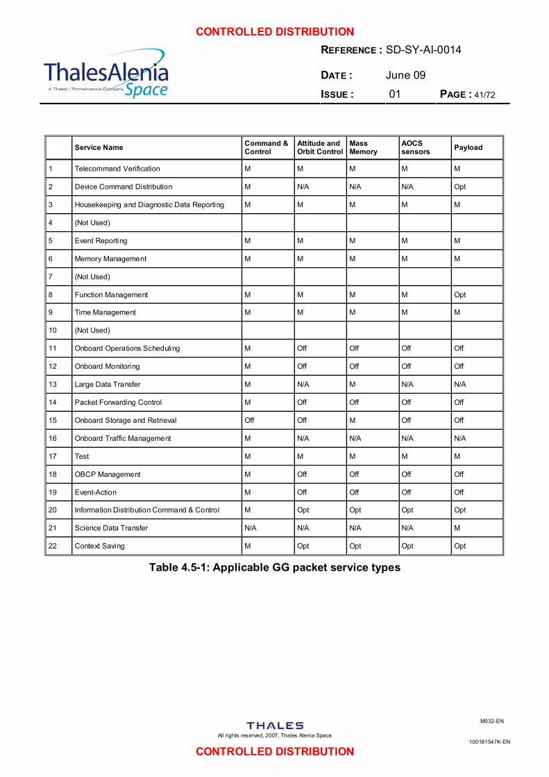
CONTROLLED DISTRIBUTION REFERENCE : DATE :
SD-SY-AI-0014 June 09
ISSUE : 01 PAGE : 41/72
All rights reserved, 2007, Thales Alenia Space
100181547K-EN
M032-EN
CONTROLLED DISTRIBUTION
Service Name Command & Control
Attitude and Orbit Control
Mass Memory
AOCS sensors Payload
1 Telecommand Verification M M M M M
2 Device Command Distribution M N/A N/A N/A Opt
3 Housekeeping and Diagnostic Data Reporting M M M M M
4 (Not Used)
5 Event Reporting M M M M M
6 Memory Management M M M M M
7 (Not Used)
8 Function Management M M M M Opt
9 Time Management M M M M M
10 (Not Used)
11 Onboard Operations Scheduling M Off Off Off Off
12 Onboard Monitoring M Off Off Off Off
13 Large Data Transfer M N/A M N/A N/A
14 Packet Forwarding Control M Off Off Off Off
15 Onboard Storage and Retrieval Off Off M Off Off
16 Onboard Traffic Management M N/A N/A N/A N/A
17 Test M M M M M
18 OBCP Management M Off Off Off Off
19 Event-Action M Off Off Off Off
20 Information Distribution Command & Control M Opt Opt Opt Opt
21 Science Data Transfer N/A N/A N/A N/A M
22 Context Saving M Opt Opt Opt Opt
Table 4.5-1: Applicable GG packet service types
CONTROLLED DISTRIBUTION REFERENCE : DATE :
SD-SY-AI-0014 June 09
ISSUE : 01 PAGE : 42/72
All rights reserved, 2007, Thales Alenia Space
100181547K-EN
M032-EN
CONTROLLED DISTRIBUTION
4.5.3 Communications Requirements
4.5.3.1 General Requirements
[ST.SCR-165] A Communications Function shall be provided to perform the following tasks:
• to receive and demodulate telecommands, • to modulate and transmit the telemetry, • to transpond the ranging signal (R).
[ST.SCR-166] The spacecraft communication subsystem shall be compatible to the current ESA standards about the issue (R).
4.5.3.2 Functional Requirements
[ST.SCR-167] The spacecraft shall be able to handle simultaneously: telecommand, telemetry and ranging (R).
[ST.SCR-168] The Ground / Board up and down links shall use the S-band (R).
[ST.SCR-169] For commanding, monitoring and control needs, Malindi ground station shall be used. If required, additional ground stations may be considered, in particular Kourou because of its near-equatorial location (R).
4.5.4 Attitude and Orbit Control Requirements
4.5.4.1 Functional Requirements
[ST.SCR-170] An Attitude & Orbit Control Function shall be provided to acquire, control and measure the required spacecraft attitude during all phases of the mission, and to produce, control and monitor all the necessary actions for the mission performance (R).
[ST.SCR-171] Upon separation from the launcher interface in a spin-axis stabilized mode drag-free and attitude control system (DFACS) shall allow compensating the effects of solar radiation pressure and atmospheric drag by reducing the common-mode drag force acting on the satellite in a narrow bandwidth (notch filter) centred at the orbital frequency (R).
[ST.SCR-172] The common mode rejection ratio of the drag free control shall be better than 1 part in 50,000, in the XY plane, at the orbit frequency (R).
[ST.SCR-173] The common mode rejection ratio of the drag free control shall be better than 1 part in 400, in the Z direction, at the orbit frequency (R).
CONTROLLED DISTRIBUTION REFERENCE : DATE :
SD-SY-AI-0014 June 09
ISSUE : 01 PAGE : 43/72
All rights reserved, 2007, Thales Alenia Space
100181547K-EN
M032-EN
CONTROLLED DISTRIBUTION
[ST.SCR-174] The common mode rejection ratio of the drag free control shall be better than 1 part in 100, in the XY plane, at the differential mode frequency (R).
[ST.SCR-175] DFACS shall provide control and measurement of satellite spin rate with relative accuracy better than 10-5 (R).
4.5.4.2 Design Requirements
[ST.SCR-176] It shall be possible for the Ground to command, via dedicated telecommands, every individual actuator (R).
[ST.SCR-177] Unambiguous status information of all command and programme controlled variables, modes and of all parameters required for subsystem monitoring and evaluation and for reconstitution on ground of the attitude and Attitude & Orbit Control manoeuvres, shall be transmitted via telemetry (R).
[ST.SCR-178] Sufficient sensor information shall be available on request in telemetry in each of the Attitude & Orbit Control modes to allow the Ground to determine the spacecraft attitude independently of the onboard system estimation process (R).
[ST.SCR-179] Sufficient information from all actuators and units involved in reaction control shall be available on request in telemetry to allow the Ground to verify the correct performance of the Attitude & Orbit Control algorithms (R).
[ST.SCR-180] An Earth elevation sensor is envisaged for measuring the inertial direction of the Earth’s centre. It shall be fixed to the satellite with two optical axes perpendicular to the spin direction, and the satellite spin provides the required scanning motion. It is expected to provide a systematic error < 0.05° and a random error< 0.01° (3σ) (R).
[ST.SCR-181] The Attitude & Orbit Control Function shall be tested at system level in end-to-end open-loop tests including sign verification and reconfiguration of all Attitude & Orbit Control units (R).
4.5.5 Electrical and Electronic Engineering Requirements
4.5.5.1 Electrical Power Requirements
General [ST.SCR-182] Electrical power is used by all active spacecraft systems and equipment for their
operation. Electrical power engineering includes power generation, energy storage, conditioning, line protection and distribution as well as high voltage engineering. Requirements related to ‘mission phases’ shall be understood as including pre-launch and launch (D).
CONTROLLED DISTRIBUTION REFERENCE : DATE :
SD-SY-AI-0014 June 09
ISSUE : 01 PAGE : 44/72
All rights reserved, 2007, Thales Alenia Space
100181547K-EN
M032-EN
CONTROLLED DISTRIBUTION
[ST.SCR-183] The design maturity margins given in Table 4.1-5 shall be applied to power at equipment level and for conventional electronic units. For the electronic equipment of the electric propulsion system (e.g. power conditioners, ion thruster drivers), the design maturity power margins shall only be applied to the dissipated power (R).
[ST.SCR-184] At the start of the Implementation Phase, a system-level margins of at least 20% of the nominal power and energy requirements of the spacecraft shall be included in the budgets (R).
Note: No system-level margin is required on the electrical power supplied to the electric propulsion system.
[ST.SCR-185] At launch, the system-level margins on available power and energy shall not be lower than 10%. As a minimum, these margins shall be available in the most power-critical mission phase, with one solar array string failed and one battery cell failed. This requirement shall be verified by analysis at each stage of the project and by test during Phase D (R).
[ST.SCR-186] The system-level power and energy margins shall be visible and traceable in the overall spacecraft power budget (R).
[ST.SCR-187] The nominal power and energy requirements include the power and energy requirements of all spacecraft elements (payload and platform, including their respective design maturity power margins to be applied at equipment level), and do not include the system-level power and energy margin (R).
[ST.SCR-188] A direct measurement of temperature, voltages, current and power ON/Off status of main power interfaces and units shall be provided to support the on-board FDIR and by TLM downlink to support the Ground FDIR (R).
[ST.SCR-189] Means and telemetry shall be provided such that the Ground can determine the state of charge of each battery throughout all mission phases, to an accuracy of better than 10% (R).
[ST.SCR-190] The spacecraft design shall comply with the following:
• in all operating modes where the power available from the solar cell generator exceeds the main bus and battery charge demand, the surplus electrical energy will be left in the solar arrays.
• in all operating modes where the power demanded from the main bus exceeds the available power from the solar cell generator, the battery charging will be stopped.
• in all operating modes where the power available from the solar cell generator is still insufficient to satisfy the load demand, electrical power will be provided from the batteries automatically.
The above functions shall be designed into one control loop covering all domains. The design of the subsystem units shall be made using simple, reliable circuitry (R).
[ST.SCR-191] For all units with a primary power consumption which varies significantly with operating temperature, a thermistor on a hot point or a primary current sensor shall be provided and made available in telemetry (R).
CONTROLLED DISTRIBUTION REFERENCE : DATE :
SD-SY-AI-0014 June 09
ISSUE : 01 PAGE : 45/72
All rights reserved, 2007, Thales Alenia Space
100181547K-EN
M032-EN
CONTROLLED DISTRIBUTION
[ST.SCR-192] The power for telemetry conditioning of equipment shall not be supplied from other unrelated units that are not permanently powered (R).
[ST.SCR-193] The power control function for vital system level units shall have a switch over function to the redundant path but never a switch-off function (R).
[ST.SCR-194] Any protection feature supporting essential functions in converters or regulators shall not be implemented in the same hybrid package or integrated circuit nor utilise common references or auxiliary supply (R).
[ST.SCR-195] With the exception of protection features such as overvoltage, over current and undefined start-up conditions which are usually backed-up by functional redundancy at equipment level, provision shall be made to override all other automatic protection features which can compromise the mission when failing (R).
[ST.SCR-196] Recovery of primary power shall be possible in any condition, even in case of loss of secondary power (R).
[ST.SCR-197] The spacecraft shall have the capability of a predefined automatic start-up after a complete loss of all main bus power. To this end, a suitable voltage level shall be defined, serving as a trigger level to define the condition of ‘complete power loss’ having been present. The proper functioning of this capability shall not depend on the speed of input power decrease or increase from the solar array. This requirement shall be verified by analysis and worst-case system level end-to-end testing, using a representative solar array electrical power simulator instead of the solar array (R).
Solar array
[ST.SCR-198] The solar array and all its components shall be qualified against the identified worst-case mission conditions, including a qualification margin (R).
[ST.SCR-199] The solar array shall satisfy each average power demand (including battery recharge power) during operational life in sunlight with one string failed. In case of an unregulated bus, adequate provision shall be made for recovery from lock-up (R).
[ST.SCR-200] Solar arrays shall be divided into several electrical sections. For high-power solar arrays (i.e. powering electric propulsion) the amount of modularity of such sections shall be optimised, having in mind the power handling capability of state-of-the-art power converter modules, as well as the requirement for one-failure tolerance. Each solar array section of a high-power solar array shall be connected through a dedicated wiring to its own power regulator circuit from which it shall be controlled (R).
[ST.SCR-201] Provision shall be made against possible failure propagation in case of failure of a solar array section and its connection to the power system (R).
[ST.SCR-202] The qualified derated current capability of slip ring contacts shall be greater than the best case solar array section current in short circuit and take into account transient currents caused by the discharge of the solar array section capacitance (R).
[ST.SCR-203] The solar array design shall take into account charging phenomena and minimise or eliminate the energy storage due to differential charging. Charging phenomena shall not affect the performance or damage the solar array (R).
CONTROLLED DISTRIBUTION REFERENCE : DATE :
SD-SY-AI-0014 June 09
ISSUE : 01 PAGE : 46/72
All rights reserved, 2007, Thales Alenia Space
100181547K-EN
M032-EN
CONTROLLED DISTRIBUTION
[ST.SCR-204] As a rule, solar array conductive structure shall not be bonded. Means shall be implemented to prevent electrostatic charging. If bleeding resistors are used for this aim, a value of no less than 10 kΩ shall be used. Bleeding resistors shall be designed with one failure tolerance (R).
[ST.SCR-205] The solar array power output evaluation shall take into account:
• I-V characteristics at BOL, EOL and the most power critical mission phase;
• operating versus maximum power point;
• blocking diodes forward voltage at operating current and lowest and highest temperature;
• BOL (i.e. calibration, seasonal effect, standard cell) and EOL (including life and radiation) loss factor;
• distribution resistance (including e.g. wiring, connectors and slip rings at the operating temperature of the mission critical power case);
• shadowing and hot spot phenomena at the most demanding mission phase;
• no loss of power in case of a short between a string and the frame; and
• no loss of more than the equivalent power of two strings in case of two shorts on the same panel (R).
Energy storage and batteries [ST.SCR-206] Batteries shall be designed to support the spacecraft through the launch sequence,
including all anticipated contingencies and through all foreseen losses of solar energy during the mission, including those resulting from failures (e.g. depointing due to loss of pointing sensors, attitude control) (R).
[ST.SCR-207] Where system requirements dictate that a battery shall tolerate a single fault, that battery shall be designed to operate with one cell either failed shorted or open circuit (R).
[ST.SCR-208] With the exception of Ni-Cd batteries for which a cell open circuit failure may be considered noncredible, each cell shall be equipped with means to bypass it in case of failure. The probability of the bypass circuit untimely operation should be lower than the probability of an open circuit failure of the cell. If the bypass operation is not instantaneous, the power system design shall take into account the transient situation. This requirement may be waived in case the used battery has been constructed from many low capacity cells connected in series and parallel to make up the battery electrical network. In this case it shall be demonstrated that a cell open circuit failure has acceptable impact on remaining available battery energy capability (R).
[ST.SCR-209] Cells making-up a battery shall be selected (matched) in accordance with the manufacturer’s recommendations (R).
[ST.SCR-210] When multiple batteries are connected in series or in parallel, matching requirements shall extend to these multiple batteries (R).
[ST.SCR-211] Sufficient extra matched spare cells shall be procured to allow for replacement of any cells damaged during integration of batteries (R).
CONTROLLED DISTRIBUTION REFERENCE : DATE :
SD-SY-AI-0014 June 09
ISSUE : 01 PAGE : 47/72
All rights reserved, 2007, Thales Alenia Space
100181547K-EN
M032-EN
CONTROLLED DISTRIBUTION
[ST.SCR-212] If batteries are connected or discharged in parallel, the current sharing shall be taken into account in the sizing of the batteries (R).
[ST.SCR-213] Battery inter-cell power connections shall be designed to minimise the series inductance and the magnetic moment (R).
[ST.SCR-214] Battery cells in a battery package having a metallic case shall be electrically isolated from each other and the battery structure by more than 1 MΩ (measured at 500 V DC). In such cases double isolation shall be applied between battery cells and battery structure. This requirement shall be verified by test (R).
[ST.SCR-215] The battery design shall include the following provisions for interfacing with the Ground Support Equipment during pre-launch operations:
• Signal lines for monitoring battery voltage, battery temperature and individual cell or cell group voltages.
• Capability to charge or discharge the battery.
• Capability to place a resistor or a shorting plug across each cell, if required by the used cell technology (R).
[ST.SCR-216] A logbook shall be maintained for each flight battery starting with the first activation after battery assembly up to launch (R).
[ST.SCR-217] The logbook shall detail chronologically all test sequences, summary of observations, identification of related computer-based records, malfunctions, names of responsible test personnel and references to test procedures (R).
[ST.SCR-218] The logbook shall be used for the following purposes:
• to ensure compliance with storage, handling and operational requirements before launch (e.g maximum time allowed at upper temperature limits, correct scheduling of maintenance activities
• and allow verification of flight worthiness (R).
[ST.SCR-219] Battery thermal design shall take into account the following (including any single cell failure if single fault tolerance is required):
• maximum and minimum temperature of cell operation under intended cycling conditions;
• maximum allowed temperature gradients between different parts of the same cell and between two cells in a battery;
• instantaneous heat generated in cells and protection devices during all phases of the mission;
• recommendations from the manufacturer for the temperature and temperature gradients values to be applied shall be followed (R).
[ST.SCR-220] If batteries are connected in parallel or in series, the maximum temperature difference between all corresponding locations in the batteries shall be limited according to manufacturers recommendations.
CONTROLLED DISTRIBUTION REFERENCE : DATE :
SD-SY-AI-0014 June 09
ISSUE : 01 PAGE : 48/72
All rights reserved, 2007, Thales Alenia Space
100181547K-EN
M032-EN
CONTROLLED DISTRIBUTION
[ST.SCR-221] In addition to the equipment level mechanical requirements imposed by the launch and other mission phases, the battery mechanical design shall take into account the following:
• maximum and minimum pressure values that can occur within cells under worst case conditions during ground operations and mission;
• manufacturer’s recommendations for cell stress limits;
• possible fatigue due to stress cycles accompanying electrical cycling (R).
[ST.SCR-222] The charging technique shall be designed to ensure that the batteries are adequately recharged without excessive overcharge under all mission phases (R).
[ST.SCR-223] Effects of aging on cell characteristics shall be accommodated (as well as the case of the single cell failure, if applicable) (R).
[ST.SCR-224] When taper charging is employed, the voltage limit above which taper charging begins should be automatically adjusted to take into account cell temperature. In order to avoid excessive overcharge, either an additional recharge ratio limit shall be implemented or selectable multiple temperature compensated voltage limits shall be available (R).
[ST.SCR-225] The charging technique shall be such as to ensure that the recharge ratio applied is appropriate for the particular cell technology, temperature of operation and cycle life requirements (R).
[ST.SCR-226] The charging technique shall ensure that the maximum allowed charge current recommended by the cell manufacturer is never exceeded and that any safety or lifetime related maximum cell voltage limit is respected. This requirement shall be verified by test (R).
[ST.SCR-227] The end of charge control shall be one fault tolerant. Protection shall be provided at cell, battery or subsystem level to ensure that no cell violates any safety or lifetime related minimum voltage or maximum discharge current (R).
[ST.SCR-228] The design of the spacecraft shall allow for removal and replacement of batteries at any time prior to launch without affecting the acceptance status of the rest of the spacecraft (R).
[ST.SCR-229] After prolonged storage, cells and batteries shall be brought slowly to the ambient temperature. Low rate conditioning cycles according to manufacturer’s specifications shall be performed to obtain nominal performance (R).
[ST.SCR-230] For the procurement of cells and batteries the procurer shall agree on precise storage and reactivation requirements as a minimum on:
• maximum ground storage life (where applicable before and after activation);
• maximum period of non-use without special “wake-up” cycling;
• maximum and minimum battery temperatures and durations during pre-launch and operational phases;
• battery maintenance during integration and pre-launch phases including case of
CONTROLLED DISTRIBUTION REFERENCE : DATE :
SD-SY-AI-0014 June 09
ISSUE : 01 PAGE : 49/72
All rights reserved, 2007, Thales Alenia Space
100181547K-EN
M032-EN
CONTROLLED DISTRIBUTION
launch delay;
• storage procedure, storage temperature, cells discharge requirements,
• humidity and packaging for storage;
• reactivation procedure after storage;
• storage procedure, storage temperature, state of charge, whether or not cells shall be individually shorted, details of any trickle charge or periodic maintenance.
The verification of these requirements shall be done by procurer/supplier agreement (R).
[ST.SCR-231] An agreement describing all these requirements shall be signed by both procurer and manufacturer (R).
[ST.SCR-232] Almost all battery technologies used aboard spacecraft can be hazardous if not properly managed. Most are capable of delivering very high currents when shorted. When abused, cells can develop excessive internal pressure and eventually vent their contents, in extreme cases explosively. The electrolyte, cell reactants, and/or reaction products expelled can be corrosive (e.g. alkaline cells, lithium-- SO2, LithiumSOCl2), flammable (e.g. lithium cell organic electrolytes) or toxic endangering any nearby personnel as well as neighbouring equipment. The principal cell failure modes which can lead to these effects are listed below:
• overtemperature (from battery thermal dissipation or environmental heating);
• excessive currents (discharge or charge) including short-circuit (external or internal to the battery);
• overcharging (in the case of primary cells, attempting to charge);
• overdischarge (including cell reversal);
• cell leakage (gases or electrolyte).
Detailed descriptions of the hazards associated with different battery chemistry are given in reference document: NASA Aerospace Battery Safety Handbook, G. Halpert, S. Subbarao & J. Rowlette, JPL Publication 86-14 (D).
[ST.SCR-233] The design rules in earlier sections which aim at maximising battery performance and cycle life also reduce the possibility that cells and batteries will exhibit failure modes such as those listed above. However, in applying the safety rules of ECSS-Q-40, some battery failure modes can be found to be critical or catastrophic and further design or management provisions shall be implemented to achieve the required level of fault tolerance (R).
[ST.SCR-234] To avoid late discovery of battery safety issues the following shall be addressed at the battery selection and design phases: All potential failure modes including those listed above and their possible consequences to personnel and equipment shall be specifically addressed (R).
[ST.SCR-235] The design of the battery and associated monitoring and control electronics shall, as far as is feasible, preclude the occurrence of any of the above. Where this is not feasible, the design shall mitigate the damaging effects of any such failure mode (e.g. containment of cell leakage at battery level) (R).
CONTROLLED DISTRIBUTION REFERENCE : DATE :
SD-SY-AI-0014 June 09
ISSUE : 01 PAGE : 50/72
All rights reserved, 2007, Thales Alenia Space
100181547K-EN
M032-EN
CONTROLLED DISTRIBUTION
Power Conditioning and Control [ST.SCR-236] No single point failure in the spacecraft, including for instance failure of wiring and
connectors, shall open or short a main electrical power bus or cause any overvoltage (R).
[ST.SCR-237] The design shall ensure that under all conditions during the required lifetime, including operation in eclipse with one battery cell open or shorted and one solar array string failed, that the main bus voltage shall remain within nominal tolerances (R).
[ST.SCR-238] In order to maximise the reuse of equipment, bus voltage types should be standardised (G).
[ST.SCR-239] For fully regulated buses, i.e. providing power day and night with a constant bus voltage, the following standard should be applied:
• 28 V for power up to 1.5 kW;
[ST.SCR-240] A fully regulated bus shall keep its nominal value in steady state of the main regulation point within ± 1% (R).
[ST.SCR-241] For load transients of up to 50% of the largest single nominal load, bus transients shall not exceed 1% (R).
[ST.SCR-242] The bus voltage shall remain within 5% of its nominal value during all source transients and largest single load transients in nominal operation (R).
[ST.SCR-243] A fully regulated bus shall have a nominal ripple voltage below 0.5% peak-to peak of the nominal bus voltage (R).
[ST.SCR-244] A fully regulated bus shall have commutation voltage spikes in the time domain of less than 2% peak-to-peak of the nominal bus voltage. (Measured with an analog oscilloscope of 50 MHz minimum bandwidth or a digital oscilloscope offering equal or better performance) (R).
[ST.SCR-245] At the point of regulation, the impedance mask of a fully regulated bus, operating with one source (e.g. battery, solar array) shall be below the impedance mask shown in Figure 4.5-2 (R).
• U = Nominal regulated output voltage (Volt)
• P = Power capability (Watt).
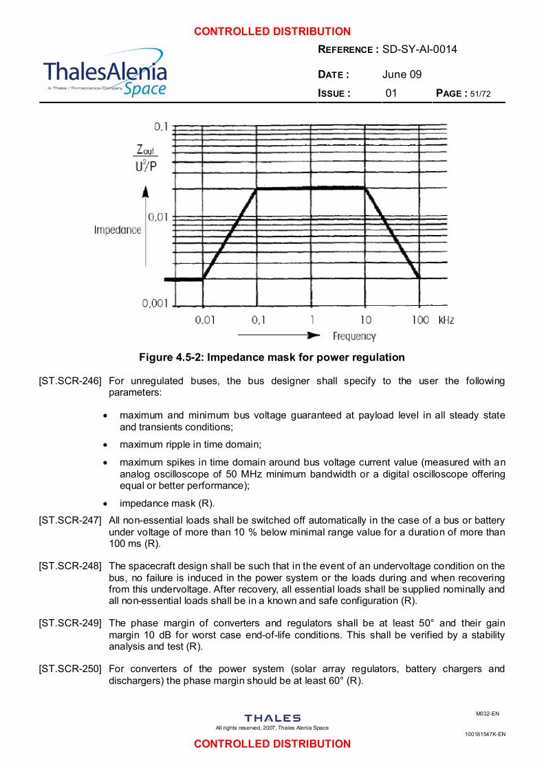
CONTROLLED DISTRIBUTION REFERENCE : DATE :
SD-SY-AI-0014 June 09
ISSUE : 01 PAGE : 51/72
All rights reserved, 2007, Thales Alenia Space
100181547K-EN
M032-EN
CONTROLLED DISTRIBUTION
Figure 4.5-2: Impedance mask for power regulation
[ST.SCR-246] For unregulated buses, the bus designer shall specify to the user the following parameters:
• maximum and minimum bus voltage guaranteed at payload level in all steady state and transients conditions;
• maximum ripple in time domain;
• maximum spikes in time domain around bus voltage current value (measured with an analog oscilloscope of 50 MHz minimum bandwidth or a digital oscilloscope offering equal or better performance);
• impedance mask (R).
[ST.SCR-247] All non-essential loads shall be switched off automatically in the case of a bus or battery under voltage of more than 10 % below minimal range value for a duration of more than 100 ms (R).
[ST.SCR-248] The spacecraft design shall be such that in the event of an undervoltage condition on the bus, no failure is induced in the power system or the loads during and when recovering from this undervoltage. After recovery, all essential loads shall be supplied nominally and all non-essential loads shall be in a known and safe configuration (R).
[ST.SCR-249] The phase margin of converters and regulators shall be at least 50° and their gain margin 10 dB for worst case end-of-life conditions. This shall be verified by a stability analysis and test (R).
[ST.SCR-250] For converters of the power system (solar array regulators, battery chargers and dischargers) the phase margin should be at least 60° (R).
CONTROLLED DISTRIBUTION REFERENCE : DATE :
SD-SY-AI-0014 June 09
ISSUE : 01 PAGE : 52/72
All rights reserved, 2007, Thales Alenia Space
100181547K-EN
M032-EN
CONTROLLED DISTRIBUTION
[ST.SCR-251] The electrical zero-volt reference of isolated converters/regulators shall be isolated from the unit case by more than 20 kΩ (R).
[ST.SCR-252] The capacitance between the zero-volt reference of isolated converters/regulators and the unit case shall be less than 50 nF (R).
[ST.SCR-253] If a switching converter is externally synchronised, it shall remaining in nominal operation for any increase or decrease of synchronising frequency, intermediate amplitude of synchronising signal or phase jumps of this signal (R).
[ST.SCR-254] Under the occurrence of any single failure, the conducted emission shall not overpass the specified limit by more than 6 dB (R).
[ST.SCR-255] The requirements on electrical power user interaction apply to power systems and electrical power users (R).
[ST.SCR-256] All load requirements shall be verified (R).
[ST.SCR-257] No load shall generate a spurious response that can damage other equipment or otherwise be detrimental to the satellite operation during bus voltage variation, either up or down, at any ramp rate, and over the full range from zero to maximum bus voltage (R).
Power Distribution and Protection [ST.SCR-258] The requirements on power distribution and protection shall be verified by analysis and
test (R).
[ST.SCR-259] The primary power source shall be grounded to the spacecraft structure at the star reference point with a low impedance able to sustain without degradation the worst case fault current (R).
[ST.SCR-260] All otherwise non-protected sections of a main bus distribution system shall be protected as a minimum by double isolation up to the first protection device (current breaker or current limiter). The double isolation assessment shall include harness, connector, wiring and PCB as relevant (R).
[ST.SCR-261] All load paths shall include protection circuitry as near as possible to source (R).
[ST.SCR-262] The use of fuses is not allowed (R).
[ST.SCR-263] Power distribution from a regulated bus voltage shall ensure a minimum voltage at load level of nominal bus voltage minus 2%, or 1 V, whichever is greater (R).
[ST.SCR-264] Relays shall be protected such that the peak voltage across the contacts at switch-off does not exceed 1.1 × bus voltage (R).
[ST.SCR-265] Equipment connected to independent, redundant power buses shall ensure that no single failure causes the loss of more than one power bus (R).
[ST.SCR-266] All current limiting devices and automatic switch off circuits shall be monitored by telemetry. The failure of the monitoring function shall not cause the protection elements
CONTROLLED DISTRIBUTION REFERENCE : DATE :
SD-SY-AI-0014 June 09
ISSUE : 01 PAGE : 53/72
All rights reserved, 2007, Thales Alenia Space
100181547K-EN
M032-EN
CONTROLLED DISTRIBUTION
to fail (R).
[ST.SCR-267] All protection elements shall be designed such that they can be tested at equipment and subsystem level (R).
[ST.SCR-268] All Latching Current Limiters (LCL) shall provide in the telemetry the LCL status and actual current reading (R).
[ST.SCR-269] No piece of harness shall be used as a mechanical support (R).
[ST.SCR-270] For transmission of power, each line shall be twisted with its return to minimise current loop area and harness inductance. In case a return through structure is used, power cables shall be routed near ground plane to minimise current loop and loop inductance (R).
[ST.SCR-271] The power distribution shall be protected in such a way that no overcurrent in a distribution wire can provoke failure propagation to another wire (R).
[ST.SCR-272] The harness inductance for a fully regulated bus, from the distribution node of the regulated bus to the load, shall be such that the break frequency is at least 5,000 Hz, i.e.:
L < R/2 f
where:
• L harness inductance in H
• R harness resistance in
• f break frequency in Hz
High Voltage Engineering [ST.SCR-273] The requirements on high voltage engineering shall be verified by analysis (R).
[ST.SCR-274] A high voltage is defined as a voltage at which partial discharges or corona effects can occur. In practice, this concerns voltages of the order of 200 V and above (R).
[ST.SCR-275] High voltage equipments shall be designed and manufactured taking into account the potential discharge phenomena according to Paschen curves in the environment encountered in flight (R).
[ST.SCR-276] The design of high voltage equipment shall be such that worst case DC and AC field strengths are less than half of the values for which breakdown can occur (R).
[ST.SCR-277] The field enhancement factors shall be controlled by the design. This applies in particular to the routing of high voltage cables (R).
[ST.SCR-278] For high voltage equipment design and testing, vacuum shall be understood as 10 Pa and below (R).
4.5.5.2 Electromagnetic Compatibility (EMC)
General
CONTROLLED DISTRIBUTION REFERENCE : DATE :
SD-SY-AI-0014 June 09
ISSUE : 01 PAGE : 54/72
All rights reserved, 2007, Thales Alenia Space
100181547K-EN
M032-EN
CONTROLLED DISTRIBUTION
[ST.SCR-279] The spacecraft shall be designed to achieve electromagnetic compatibility (EMC) between all equipment and subsystems within the spacecraft and in the presence of its self-induced and external electromagnetic environment (R).
[ST.SCR-280] The spacecraft shall also be designed to achieve electromagnetic compatibility (EMC) with the relevant launcher requirements (R).
[ST.SCR-281] EMC shall cover all frequencies (including DC where applicable) and fields, which fall in either the spacecraft, the payload instruments or the launcher bandwidth (R).
[ST.SCR-282] Electromagnetic interference safety margins shall be mandatory and shall be determined for critical signals, pyrotechnics, and power circuits under all operating conditions (R).
[ST.SCR-283] The minimum acceptable safety margins shall be 6 dB for power and signal circuits and 20 dB for pyrotechnic circuits (R).
[ST.SCR-284] In cases were the required minimum system margins for either power and signal circuits or for pyrotechnic circuits between emissions and susceptibility are not met, the susceptibility threshold shall be determined on subsystem, equipment, or component level (R).
[ST.SCR-285] EMI characteristics (emission and susceptibility) shall be controlled to the extent necessary to ensure intra-system EMC, and compatibility with the predicted external electromagnetic environment, including the launcher (R).
[ST.SCR-286] Spacecraft shall exhibit RF compatibility among all antenna-connected equipments/subsystems, subject to mission requirements. This requirement shall also be applicable on an inter-system basis, when an inter-system interface is required (R).
[ST.SCR-287] The RF compatibility analysis shall include the effects of intermodulation products (R).
[ST.SCR-288] Electrical bonding measures shall be implemented for management of electrical current paths and control of voltage potentials to ensure required spacecraft performance and to protect both personnel and platform. Bonding provisions shall be compatible with other requirements imposed on the spacecraft for corrosion control (R).
[ST.SCR-289] Antenna structures relying on a counterpoise connected to (or implemented on) the spacecraft skin shall have an RF bond to the structure of the spacecraft such that RF currents flowing in the skin have a low impedance path to and through the counterpoise (R).
[ST.SCR-290] All electronic and electrical items whose performance can be degraded or which can degrade the operation of the other electronic or electrical items due to the effects of electromagnetic energy shall be bonded to the ground subsystem. Individual bond straps or connections shall have a DC resistance of less than 2.5 mΩ. For composite materials, bonding shall be accomplished at impedance levels consistent with the materials in use (R).
[ST.SCR-291] Isolated conducting items subject to energetic electrons and plasma or frictional charging shall be bonded to the spacecraft ground subsystem to prevent a differential build-up of charge that can result in an electrostatic discharge, unless it is shown that no hazard exists (R).
CONTROLLED DISTRIBUTION REFERENCE : DATE :
SD-SY-AI-0014 June 09
ISSUE : 01 PAGE : 55/72
All rights reserved, 2007, Thales Alenia Space
100181547K-EN
M032-EN
CONTROLLED DISTRIBUTION
[ST.SCR-292] Power, signal returns and references shall be considered. Impedance magnitudes over the affected signal spectrum shall be taken into account when determining which kinds of power and signals share common paths (wire or structure) (R).
Spacecraft charging protection [ST.SCR-293] The spacecraft charging protection programme shall include:
• the preparation and maintenance of an analysis plan, and
• the preparation and maintenance of a test plan (R).
[ST.SCR-294] The object of the programme shall ensure that the space vehicle is capable of operating in the specified space plasma charging environment and its energetic electron content without degradation of the specified space vehicle capability and reliability and without changes in operational modes, location, or orientation. The performance shall be accomplished without the benefit of external control such as commands from a ground station. The spacecraft charging protection program, the analysis plan, and the test plan shall be subject to approval by the customer (R).
[ST.SCR-295] The following design requirements shall be implemented to protect against spacecraft charging hazards (R).
[ST.SCR-296] All conducting spacecraft vehicle elements shall be tied to an electrical grounding system, such that the DC resistance between any two points is generating a maximum differential voltage which safely avoids arc discharging under worst-case space plasma currents impinging on the elements in question, unless lower differential voltage values are required from elsewhere (e.g. grounding plane) (R).
[ST.SCR-297] All thin (<10 µm) conducting surfaces on dielectric materials shall be electrically grounded to the common space vehicle structural ground such that the DC resistance between the surface and the structure is less than 10 Ω DC (R).
[ST.SCR-298] The resistance levels of ground and bonds shall be verified by standard ohm meter and bond meter measurements. The term “thin conducting surfaces” shall include all metallised surfaces of multi-layer insulation (MLI) thermal blankets, metallised dielectric materials in form of sheets, strips, tapes, or tiles, conductive coatings, conductive paints, conductive adhesives, and metallic grids or meshes (R).
[ST.SCR-299] All electronic cables shall be provided with EMI shielding to attenuate radiated fields from discharges (100 kHz to 1 GHz) by at least 40 dB. Attenuation levels of radiated fields shall be verified by standard measurement techniques or by analysis for representative locations internal to shielding enclosures. The method of verification shall be subject to approval by the customer (R).
[ST.SCR-300] The shielding may be provided by the basic space vehicle structure designed as a “Faraday cage” with a minimum of openings or penetrations, by enclosures of electronics boxes, by separate cable shielding, or by combinations of the preceding shields. Electronics units and cables external to the basic space vehicle structure shall have individual shields providing 40 dB attenuation to EMI (R).
CONTROLLED DISTRIBUTION REFERENCE : DATE :
SD-SY-AI-0014 June 09
ISSUE : 01 PAGE : 56/72
All rights reserved, 2007, Thales Alenia Space
100181547K-EN
M032-EN
CONTROLLED DISTRIBUTION
[ST.SCR-301] Materials used in the space vehicle design shall be selected to minimise absolute and differential surface and internal charging and their subsequent discharge effects in the specified environment while maintaining the specified performance capabilities (R).
[ST.SCR-302] Materials used externally or internally should be tested or analysed to determine their charging and discharging characteristics in the specified environment (G).
Magnetic cleanliness [ST.SCR-303] The spacecraft design shall aim for magnetic cleanliness when implementing internal
design (e.g. harness twisting, routing of currents to avoid current loops) (R).
Verification requirements [ST.SCR-304] A verification matrix shall be established within the verification document. This matrix
shall show all combinations of individual equipment/subsystems, which shall be tested in order to verify overall intra-system compatibility (R).
[ST.SCR-305] Special support equipment shall be available to exercise culprits and victims, and detailed support equipment instructions shall be included (R).
[ST.SCR-306] Each item of equipment and subsystem shall meet the requirements of its functional acceptance test procedure as installed on the platform, prior to system level EMC test (R).
[ST.SCR-307] Safety margins shall be demonstrated at system level. If done by test, the spacecraft suite of equipment and subsystems shall be operated in a manner simulating actual operations (R).
[ST.SCR-308] The system level requirements, imposed to control electromagnetic interference [EMI] shall be supported by prior verification of equipment and subsystem performance accordingly (R).
[ST.SCR-309] Conformance to electrical bonding requirements shall be verified by test, analysis or inspection as appropriate for the particular bonding provision. Compatibility with corrosion control techniques shall be verified by demonstration that manufacturing processes which address corrosion control had been implemented (R).
[ST.SCR-310] Bonding of discharge elements, thermal blankets, or metallic items removed from structure and requiring a bond for static potential equalisation shall be verified by test (R).
[ST.SCR-311] Immunity to electrostatic discharge shall be verified. Since ESD testing can cause catastrophic failure of the test article (and even more insidiously, latent failures) verification is only possible on engineering or prototype models, not on the flight article (R).
[ST.SCR-312] Adequate control of static charging, plasma/payload induced differential charging/discharges and internal charging effects shall be verified by analysis or inspection as appropriate (R).
CONTROLLED DISTRIBUTION REFERENCE : DATE :
SD-SY-AI-0014 June 09
ISSUE : 01 PAGE : 57/72
All rights reserved, 2007, Thales Alenia Space
100181547K-EN
M032-EN
CONTROLLED DISTRIBUTION
4.5.6 Radio Frequency Systems
[ST.SCR-313] Radio frequency (RF) systems have the goal of performing downlink communication of science and telemetry/housekeeping data and uplink communication of telecommand data. They include transmitters, receivers, antennas and their associated transmission lines including connectors. Transmitters and receivers require high mutual isolation (D).
[ST.SCR-314] The requirements below shall be verified by analysis (R).
[ST.SCR-315] To achieve the RF performance requirements, the engineering processes shall consider the following parameters:
• antenna field of view and polarisation;
• link or radiometric budget;
• frequency plan (R).
[ST.SCR-316] To achieve the performances requirement, the RF design and development shall consider the following parameters:
• transmitter power;
• receiver sensitivity;
• multipaction;
• VSWR;
• frequency stability;
• spectral purity;
• isolation between transmitter and receiver (R).
[ST.SCR-317] Definition of the following antenna terms shall conform to IEEE Standard 145-1993:
• antenna;
• directivity;
• electrical boresight;
• gain;
• impedance mismatch factor;
• radiation pattern;
• radiation pattern cut;
• sense of polarisation;
• side lobe;
• axial ratio;
• noise temperature (R).
CONTROLLED DISTRIBUTION REFERENCE : DATE :
SD-SY-AI-0014 June 09
ISSUE : 01 PAGE : 58/72
All rights reserved, 2007, Thales Alenia Space
100181547K-EN
M032-EN
CONTROLLED DISTRIBUTION
4.5.7 Mechanical Engineering Requirements
4.5.7.1 Thermal Control Requirements
[ST.SCR-318] Chapter 3 of ECSS-E-30 Part 1 ([SD 4]) shall apply with the additions and modifications listed hereunder (R).
[ST.SCR-319] Passive thermal control, based on multi-layer insulation (MLI) blankets and heaters, will be adopted (R).
[ST.SCR-320] Dimensioning of the Thermal Control shall cover worst-case scenarios derived from every mission phase up to the end of the operating lifetime, and worst combination of expected physical properties (BOL/EOL) and operative conditions and Safe Modes, as defined in Thermal Environment section (R).
[ST.SCR-321] Structural parts shall be kept as a whole within temperature, temperature gradient and temperature stability ranges required to ensure the integrity and performance of the spacecraft during all nominal and non-nominal mission phases (R).
[ST.SCR-322] DFACS equipment (in particular: FEEP thrusters, if present) and main engines valves temperatures shall be kept within their design ranges when in non-operative, pre-firing and soak-back conditions for all mission scenarios, and, in particular, for all envisaged Sun-illumination conditions (R).
[ST.SCR-323] Sufficient temperature sensors for in-flight monitoring of units, structural parts and propulsion temperatures shall be provided to verify compliance with temperature, temperature gradients and temperature stability requirements, and to enable Ground intervention during nominal and non-nominal phases of the mission (R).
[ST.SCR-324] The capability shall be provided to adjust the temperature control thresholds of each software-controlled thermal control loop by Ground command (R).
[ST.SCR-325] Temperature control functions provided by heaters shall be protected against failure by redundancy of the complete chain (R).
[ST.SCR-326] The spacecraft shall be able to withstand the foreseen thermal environment and the temperature levels and thermal cycling encountered during all mission phases, taking into account any possible environmentally induced degradation of materials and their properties (R).
[ST.SCR-327] Thermal insulation properties of actual configuration of blankets and attachment fastening methods assumed in the design shall be substantiated by analysis (R).
[ST.SCR-328] ESATAN and ESARAD shall be used for the system thermal analyses (R).
[ST.SCR-329] The Thermal Mathematical Models (TMMs) shall unambiguously identify the flight and the test monitoring points (R).
[ST.SCR-330] ESATAN shall be used for exchange of Thermal Mathematical Models (R).
CONTROLLED DISTRIBUTION REFERENCE : DATE :
SD-SY-AI-0014 June 09
ISSUE : 01 PAGE : 59/72
All rights reserved, 2007, Thales Alenia Space
100181547K-EN
M032-EN
CONTROLLED DISTRIBUTION
[ST.SCR-331] ESARAD shall be used for exchange of Geometrical Mathematical Models (R).
[ST.SCR-332] A reduced Thermal Mathematical Model of the entire spacecraft in its launch configuration shall be derived and correlated with the Detailed Thermal Mathematical Model (DTMM) for the integrated analyses with the launcher. The format of this model shall be in accordance with the requirements of the Launcher Interface Control Document (R).
[ST.SCR-333] The compliance to the thermal performance requirements shall be demonstrated by analysis for all worst-case mission scenarios. Thermal analyses shall be carried out in compliance with Annex A.5 of ECSS-E-30 Part 1. Temperature uncertainties shall be established according to the methods of Annex A.1 of ECSS-E-30 Part 1 (R).
[ST.SCR-334] The heat load capability of any heat pipe shall be at least 1.25 times the calculated transported heat load when one of its adjacent heat pipes is considered failed. The calculated heat load shall be derived by thermal analysis (R).
[ST.SCR-335] A set of failure cases shall be simulated to demonstrate compliance with single failure tolerance requirement (R).
4.5.7.2 Structural Requirements
[ST.SCR-336] Chapter 3 of ECSS-E-30 Part 2 ([SD 5]) shall apply (R).
[ST.SCR-337] All structural assemblies and components shall be designed to withstand applied loads due to the natural and induced environments to which they are exposed during the service life and shall be able, in operation, to fulfil the mission objectives for the nominal mission lifetime and extended mission lifetime. In particular, the following failure modes shall be prevented:
• permanent deformation, yield; • rupture; • instability, buckling; • gapping of bolted joints; • degradation of bonded joints; • mounting interface slip induced by vibration; • loss of alignment of equipment and payload subject to alignment requirements; • distortion violating any specified envelope; • distortion causing functional failures or damage to other subsystems (R).
[ST.SCR-338] Loads shall be defined according to their nature, whether static or dynamic, the magnitude, direction and timing with respect to the events during the service-life. As a minimum the following load events shall be considered:
1. Ground loads due to: • handling, transportation and storage; • manufacturing, assembly and integration; • testing.
2. Launch loads: • longitudinal and lateral quasi-static loads;
CONTROLLED DISTRIBUTION REFERENCE : DATE :
SD-SY-AI-0014 June 09
ISSUE : 01 PAGE : 60/72
All rights reserved, 2007, Thales Alenia Space
100181547K-EN
M032-EN
CONTROLLED DISTRIBUTION
• sinusoidal loads; • random and acoustic loads; • shocks; • depressurisation.
3. In-orbit loads: • static and dynamic acceleration induced by thruster firing; • thermo-elastic loads induced by temperature evolution; • shocks due to pyrotechnical operation and deployment of appendages (R).
[ST.SCR-339] A Structural or Structural-Thermal Model of the spacecraft shall pass successfully the environmental qualification test campaign (R).
[ST.SCR-340] The Flight Model of the spacecraft shall pass successfully the environmental acceptance test campaign (R).
[ST.SCR-341] The structure shall be of adequate strength to withstand the design loads without yielding, buckling, rupture or exhibiting excessive deformations that can endanger the mission objectives (R).
[ST.SCR-342] Local buckling shall be tolerated only if it is reversible and under the condition that the resulting stiffness and deformation remain in conformance with the structural requirements without risk of general buckling being induced by local instability (R).
[ST.SCR-343] The lowest eigenfrequencies and the effective masses of the spacecraft in launch configuration, hard mounted to its interface with the launcher, shall be in accordance with the values specified in the Launcher Interface Control Document (R).
[ST.SCR-344] The structure constrained for launch shall present a first axial mode not compliant to 20 Hz (launcher reference requirement) (R).
[ST.SCR-345] The design shall maximize the moment of inertia JZ with respect to the symmetry axis, thereby providing passive spin stabilization around it (R).
[ST.SCR-346] The dimensional stability of the structure shall comply with the system-level pointing requirements. The following causes of misalignment shall be taken into account:
• setting due to mounting procedures; • setting due to launch distortions; • misalignments due to gravity release in 0-g environment; • thermo-elastic deformations due to temperatures variation; • aging and creeping; • moisture release of composite structures.
[ST.SCR-347] The limit loads (LL) shall be derived as follows:
• for cases where a representative statistical distribution of the loads is known, the limit load shall be defined as the load level not to be exceeded with a probability of 99% and a confidence level of 90% during the service-life;
• for cases where a statistical distribution of the loads is not known the limit loads shall be based on conservative assumptions;
• the mechanical part of the LL, acting during launch at the spacecraft interface, shall be derived from the launcher interface control document (R).
CONTROLLED DISTRIBUTION REFERENCE : DATE :
SD-SY-AI-0014 June 09
ISSUE : 01 PAGE : 61/72
All rights reserved, 2007, Thales Alenia Space
100181547K-EN
M032-EN
CONTROLLED DISTRIBUTION
[ST.SCR-348] Margins of safety (MOS) shall be calculated by the following formula: (allowable loads)/(applicable loads X FOS)-1, where:
• allowable load: allowable load under the considered failure conditions (e.g. yield, buckling, ultimate);
• applied load: computed or measured load under defined load conditions (Design Loads);
• FOS: factor of safety applicable to the considered failure condition (R). Note: Margins of safety express the margin of the applied load multiplied by a factor of safety against the allowed load. Loads can be replaced by stresses if the load-stress relationship is linear.
[ST.SCR-349] For the verification of mechanical design all structural finite element models (FEM) shall be delivered in NASTRAN format (R).
[ST.SCR-350] A reduced FEM of the entire spacecraft in launch configuration shall be delivered and correlated with the detailed spacecraft FEM for the launcher coupled load analysis, fulfilling the requirements of the launcher authorities (R).
[ST.SCR-351] Modal analysis shall be performed to verify the frequency requirements and to determine associated modal characteristics (e.g. natural frequencies, eigenmodes, effective masses, participation factors, generalised masses). The following minimum margins over the specified frequencies shall be demonstrated when considering the mass of each unit or component equal to their maximum allocated mass:
• start of Implementation Phase: 20% • at Preliminary Design Review: 15% • at Critical Design Review: 10% • at Flight Acceptance Review: 0% (R).
[ST.SCR-352] Test verification for equipment shall be performed in accordance with ECSS-E-10-02 (R).
[ST.SCR-353] Verification of the functionality requirements of the structure shall be possible by test at element, subassembly or system level (R).
[ST.SCR-354] Qualification and acceptance environmental test campaigns shall include all the mechanical tests required by the mechanical design verification requirements specified by the Launcher Authority. These include static test, sinusoidal vibration test, random vibration test, acoustic vibration test, clamp-band release shock test (R).
[ST.SCR-355] Qualification loads (QL) shall be equal to: QL = KQ × LL where KQ = 1.3 as a minimum for in-flight loads, 1.5 for ground operations and transportation loads (R).
[ST.SCR-356] Any structural element shall demonstrate by test the capability of withstanding its qualification loads (for qualification) or its acceptance loads (for acceptance) (R).
4.5.7.3 Mechanisms Requirements
[ST.SCR-357] Chapter 3 of ECSS-E-30 Part 3 ([SD 6]) shall apply (R).
[ST.SCR-358] In GG satellite launch-lock mechanisms shall be designed to initially constrain the payload test masses (R).
CONTROLLED DISTRIBUTION REFERENCE : DATE :
SD-SY-AI-0014 June 09
ISSUE : 01 PAGE : 62/72
All rights reserved, 2007, Thales Alenia Space
100181547K-EN
M032-EN
CONTROLLED DISTRIBUTION
[ST.SCR-359] After their release test masses shall be constrained by inch-worm devices (R).
[ST.SCR-360] The mechanism engineering shall consider every phase of the mission and conform to the related mission requirements and environmental constraints (R).
[ST.SCR-361] The thermal design of the mechanism shall meet the requirements specified in the Thermal Control Requirements section (R).
[ST.SCR-362] Mechanisms shall be designed so that they cannot be driven into a non recoverable condition (R).
4.5.7.4 Propulsion Requirements
[ST.SCR-363] Chapter 3 of ECSS-E-30 Part 5.1 ([SD 7]) shall apply (R).
[ST.SCR-364] The performances of the propulsion system, in terms of total impulse, thrust levels, torques and margins, shall satisfy the requirements imposed by the trajectory analysis and the system requirements (R).
[ST.SCR-365] The propulsion system shall conform to the spacecraft mission requirements with respect to: pre-launch and launch activities (i.e. integration, storage, aging and transport), in-orbit operation (i.e. orbit change manoeuvres and attitude control) and during the complete mission life; ground operations, i.e. functional control, testing, propellant loading, simulation of loading and offloading, spacecraft transportation (R).
[ST.SCR-366] It shall be possible to evaluate the consumed propellant and delivered thrust level from the specific propulsion system sensors together with the rest of the spacecraft telemetry according to the mission needs (R).
[ST.SCR-367] The characteristics of the thrusters and their accommodation on the spacecraft shall not cause deterioration due to plume impingement and contamination to solar arrays (before and after deployment), thermal control sensitive surfaces, spacecraft optics and sensors (R). Note: this is mainly important for the accommodation and design features of the DFACS control thrusters.
[ST.SCR-368] Drag-free control thrusters will be accommodated in two clusters of 3 each, with orientations providing sufficient torque and force authority on all axes (R).
[ST.SCR-369] For DFACS baseline option is using FEEP micro thrusters. As alternative, cold gas micro thrusters are taken in account. System design shall accommodate and provide enough resources for the selected equipments (R).
[ST.SCR-370] Propulsion subsystem design shall provide the necessary redundancy to the units in order to allow performance of required tasks (R).
[ST.SCR-371] Each thruster shall be equipped with a neutralizer device to prevent charging of the spacecraft (R).
CONTROLLED DISTRIBUTION REFERENCE : DATE :
SD-SY-AI-0014 June 09
ISSUE : 01 PAGE : 63/72
All rights reserved, 2007, Thales Alenia Space
100181547K-EN
M032-EN
CONTROLLED DISTRIBUTION
4.5.7.5 Pyrotechnics Requirements
[ST.SCR-372] ECSS-E-30 Part 6 ([SD 8]) shall apply (R).
4.5.7.6 Mechanical Parts Requirements
[ST.SCR-373] Mechanical parts selection shall be in accordance with ECSS-E-30 Part 7 ([SD 9]) (R).
4.5.7.7 Materials Requirements
[ST.SCR-374] Material selection shall be in accordance and ECSS-E-30 Part 8 ([SD 10]) (R).
4.5.8 Software Engineering Requirements
4.5.8.1 Software Design
[ST.SCR-375] All onboard software shall be developed using a high level language, except where explicitly exempted, exception shall only be given for small modules where the needed performance cannot be obtained using a high level language (R).
[ST.SCR-376] The software developed shall be in two stand-alone packages for each hardware unit:
• Initialisation software
• Full mission software
They shall not run in parallel on the same CPU (R).
[ST.SCR-377] The mission software shall include all software required for execution of all mission phases (R).
[ST.SCR-378] All mission software shall be updatable by the Ground during the mission. Software for designated main units shall boot to full operational status. Software for designated redundant units shall only boot the initialisation software (R).
[ST.SCR-379] The mission software shall not use more than 75% of the processor time per basic cycle. Software shall be segmented into modules by function. Each module shall be further segmented into code, constant and variables (R).
[ST.SCR-380] Each module shall be allocated 5% spare memory area, adjacent to it in the RAM memory map to allow for maintenance by patch. When a processor cannot support the direct addressing of all RAM each directly addressable segment shall have 5% spare memory allocated, this spare shall be in addition to the spare allocated to the SW modules in that segment (R).
[ST.SCR-381] All input and output data for each module shall be documented with the module as comments with the source code (R).
CONTROLLED DISTRIBUTION REFERENCE : DATE :
SD-SY-AI-0014 June 09
ISSUE : 01 PAGE : 64/72
All rights reserved, 2007, Thales Alenia Space
100181547K-EN
M032-EN
CONTROLLED DISTRIBUTION
[ST.SCR-382] It shall be possible to compile a module as a stand alone SW element and produce a binary image of the compiled module (R).
[ST.SCR-383] A module shall not clear or otherwise modify input data (R).
[ST.SCR-384] Each data element that is passed between modules shall be documented showing the meaning of the data, which module generates it and which modules use it (R).
[ST.SCR-385] The software shall be built using references to the spacecraft database (R).
[ST.SCR-386] The capability shall be provided to save the operational context in non-volatile memory so that it can be restored if a processor is reset or temporarily switched off (R).
[ST.SCR-387] The resources utilised by onboard software shall be telemetered (e.g., memory usage, central processor unit (CPU) usage and I/O usage). Any communication between the Ground and an onboard software function or software task shall be effected by means of telecommand and telemetry source packets specifically designed for the purpose (R).
[ST.SCR-388] An event report shall be generated in the following situations:
• a condition that forces a processor reset is detected by software • a processor overload condition is detected • an unexpected arithmetic overflow condition is detected • an illegal programme instruction is encountered during execution of a program
code • a data bus error is detected by software • a memory corruption is detected by an error detection and correction mechanism • a checksum error is detected • an internal inconsistency is detected (R).
The event reports that are generated in the case of a failure shall indicate the type of the failure, its location and any additional information needed for failure diagnosis.
[ST.SCR-389] The Command & Control Function system and application software shall reside on a non volatile onboard mass memory and loaded from that memory into working memory at time of boot-up. Two identical copies (main and redundant) of the above files shall be stored on the mass memory.
[ST.SCR-390] Enabling of onboard software should use only a single telecommand (R).
[ST.SCR-391] The software test environment used pre-launch has to be ported to the software maintenance environment used in the operational phase (R).
4.5.8.2 Software Test and Validation
[ST.SCR-392] A Software Test Bed (STB) shall be used by each software developer to support software development, testing, validation and maintenance. This means that the STB shall be based on the target processor and not made a common item for the whole project.
[ST.SCR-393] A Software Validation Facility (SVF) shall be used for software validation and testing. This SVF shall provide a numerical simulation of the target hardware environment.
CONTROLLED DISTRIBUTION REFERENCE : DATE :
SD-SY-AI-0014 June 09
ISSUE : 01 PAGE : 65/72
All rights reserved, 2007, Thales Alenia Space
100181547K-EN
M032-EN
CONTROLLED DISTRIBUTION
[ST.SCR-394] For software that is selected for Independent Software Validation (ISV) the same STB/SVF can be used or other agreed methods applied depending on the ISV to be performed.
[ST.SCR-395] The STB shall execute the software under test in the same hardware and operational environment as the onboard target (R).
[ST.SCR-396] Software identified as mission critical shall be the subject of ISV (R).
[ST.SCR-397] After selection of the software items for ISV the validation method shall be agreed, defining test approach and tools needed to meet the validation objective (R).
[ST.SCR-398] The defined ISV shall be performed on the selected software before formal delivery of the software and shall form part of the acceptance review (R).
[ST.SCR-399] All ISV tests shall be automatic and deliverable (R).
[ST.SCR-400] ISV tests shall be performed on the final flight software, depending on the software delivery schedule ISV tests on a pre-final version may also be performed (R).
4.5.8.3 Software Design and Implementation
[ST.SCR-401] The following software development and design processes:
• Engineering Processes Related to Software • Requirement and Architecture Engineering • Design and Implementation Engineering • Validation • Delivery and Acceptance
shall be done in accordance to ECSS-E-40 ([SD 11]) document (R).
4.6 Launch Service Segment Interface Requirements
[ST.LIR-1] The spacecraft design shall be fully compatible with:
i. all performances, requirements, interfaces and operations of VEGA launcher specified in the launcher interface control document;
ii. all performances, requirements, interfaces and operations of at least another low cost launcher, as specified in the its interface control document;
iii. the operations and safety requirements applicable at the selected ground segment/launch site (R).
[ST.LIR-2] During the launch and ascent phases when attached to the launcher, the spacecraft shall be compliant with the attitude profile of the launcher (R).
CONTROLLED DISTRIBUTION REFERENCE : DATE :
SD-SY-AI-0014 June 09
ISSUE : 01 PAGE : 66/72
All rights reserved, 2007, Thales Alenia Space
100181547K-EN
M032-EN
CONTROLLED DISTRIBUTION
5. GROUND SEGMENT REQUIREMENTS
[ST.GSR-1] The spacecraft shall be able to interface with the ASI Ground Segment. The applicable requirements for this interface are defined in the space-to-ground interface control document (R).
[ST.GSR-2] The spacecraft shall be able to fulfil the science data downlink requirements (R).
[ST.GSR-3] In LEOP additional support ground stations shall be foreseen (in addition to nominal Ground Segment stations operating in nominal phase) to provide a TBD coverage of the spacecraft orbit and to perform the following tasks:
i. observe the on-board status after separation,
ii. guarantee the spacecraft command and control link during all critical operations,
iii. perform orbit determination (R).
CONTROLLED DISTRIBUTION REFERENCE : DATE :
SD-SY-AI-0014 June 09
ISSUE : 01 PAGE : 67/72
All rights reserved, 2007, Thales Alenia Space
100181547K-EN
M032-EN
CONTROLLED DISTRIBUTION
6. VERIFICATION REQUIREMENTS
[ST.VER-1] Verification requirements provided by the GG Mission System Assembly, Integration and Verification (AIV) Requirements Document, to be issued in accordance to [SD 3], shall apply (R).
CONTROLLED DISTRIBUTION REFERENCE : DATE :
SD-SY-AI-0014 June 09
ISSUE : 01 PAGE : 68/72
All rights reserved, 2007, Thales Alenia Space
100181547K-EN
M032-EN
CONTROLLED DISTRIBUTION
7. PRODUCT ASSURANCE REQUIREMENTS
[ST.PAR-1] Product assurance requirements provided by the GG Mission Product Assurance Requirements Document, to be issued in accordance to [SD 13], shall apply. Tailoring of PA requirements standards shall be performed according to [SD 1] (R).
CONTROLLED DISTRIBUTION REFERENCE : DATE :
SD-SY-AI-0014 June 09
ISSUE : 01 PAGE : 69/72
All rights reserved, 2007, Thales Alenia Space
100181547K-EN
M032-EN
CONTROLLED DISTRIBUTION
8. DOCUMENTS
8.1 Overview
The Applicable Documents listed below shall be complied with during the GG Phase A2 Study, unless where specifically stated. In such an event, ASI shall be notified and shall decide on course of action. It is expected that some of the documents will be completed and matured as the assessment phase progresses.
The published ECSS (European Cooperation for Space Standardisation) space standards documents quoted in the STS are applicable throughout the GG Phase A2. The Reference Documents listed below are given as complementary information and background data related to the GG Mission.
8.2 Applicable Documents
[AD 1] ASI, “Progetto Galileo Galilei-GG Fase A-2, Capitolato Tecnico”, DC-IPC-2007-082, Rev. B, October 2007 and applicable documents defined therein
[AD 2] “Galileo Galilei Mission Requirement Document”, SD-TN-AI-1167, Issue 2, June 2009
[AD 3] “Experiment Concept and Requirements Document (ERD)”, SD-TN-AI-1163, Issue 2, March 2009
8.3 Standards
[SD 1] ECSS-M-00-02A, Space Project Management – Tailoring of Space Standards, 25 April 2000
[SD 2] ECSS-E-10 Part 1, System engineering
[SD 3] ECSS-E-10-02A, Space Engineering – Verification
[SD 4] ECSS-E-30, Space Engineering - Mechanical - Part 1: Thermal
[SD 5] ECSS-E-30, Space Engineering - Mechanical - Part 2: Structural
[SD 6] ECSS-E-30, Space Engineering - Mechanical - Part 3: Mechanism
[SD 7] ECSS-E-30, Space Engineering - Mechanical - Part 5: Propulsion
[SD 8] ECSS-E-30, Space Engineering - Mechanical - Part 6: Pyrotechnics
[SD 9] ECSS-E-30, Space Engineering - Mechanical - Part 7: Mechanical Parts
[SD 10] ECSS-E-30, Space Engineering - Mechanical - Part 8: Materials
[SD 11] ECSS-E-40 Part 1, Software Engineering Standards
[SD 12] ECSS-E-ST-60-10C Control Performance
CONTROLLED DISTRIBUTION REFERENCE : DATE :
SD-SY-AI-0014 June 09
ISSUE : 01 PAGE : 70/72
All rights reserved, 2007, Thales Alenia Space
100181547K-EN
M032-EN
CONTROLLED DISTRIBUTION
[SD 13] ECSS-Q-00A, Space Product Assurance - Policy and Principles, and related Level 2 standards.
[SD 14] ECSS-Q-ST-70-01C, Cleanliness and contamination control, 15 November 2008
8.4 Reference Documents
[RD 1] GG Phase A-2 Study Report, April 2009
[RD 2] GG Phase A Study Report, November 1998, revised January 2000, available at: http://eotvos.dm.unipi.it/nobili/ggweb/phaseA/index.html
[RD 3] Supplement to GG Phase A Study (GG in sun-synchronous Orbit) “Galileo Galilei-GG”: design, requirements, error budget and significance of the ground prototype”, A.M. Nobili et al., Physics Letters A 318 (2003) 172–183, available at the following official website: http://eotvos.dm.unipi.it/nobili/documents/generalpapers/GG_PLA2003.pdf
CONTROLLED DISTRIBUTION REFERENCE : DATE :
SD-SY-AI-0014 June 09
ISSUE : 01 PAGE : 71/72
All rights reserved, 2007, Thales Alenia Space
100181547K-EN
M032-EN
CONTROLLED DISTRIBUTION
9. ACRONYMS
AD Applicable Document AOCS Attitude and Control Subsystem ASI Agenzia Spaziale Italiana CCSDS Consultative Committee for Space Data Systems CNES Centre National d’Etudes Spatiales CPE Control and Processing Electronics DFACS Drag Free Attitude and Control Subsystem DoD Depth of Discharge ECE Experiment Control Electronics ECSS European Cooperation for Space Standardisation EP Equivalence Principle ESA European Space Agency FEM Finite Element Model FOS Factor of Safety G/S Ground Station GG Galileo Galilei HK Housekeeping INFN Istituto Nazionale di Fisica Nucleare IORF Inertial Orbit Reference Frame ISV Independent Software Validation LEOP Launch and Early Orbit Phase LL Limit Loads MLI Multi Layer Insulation MRD Mission Requirement Document OBCP Onboard Control Procedure P/L Payload PA Product Assurance PCB Pico Gravity Box PPRF Payload Physical Reference Frame QL Qualification Loads RD Reference Document SD Standard Document SPRF Satellite Physical Reference Frame STS System Technical Specification S/C Spacecraft S/S Subsystem SEL Single Event Latch-Up SEU Single Event Upset SPoF Single Point of Failures STB Software Test Bed SVF Software Validation Facility TBC To Be Controlled TBD To Be Defined TC Telecommand TM Telemetry
CONTROLLED DISTRIBUTION REFERENCE : DATE :
SD-SY-AI-0014 June 09
ISSUE : 01 PAGE : 72/72
All rights reserved, 2007, Thales Alenia Space
100181547K-EN
M032-EN
CONTROLLED DISTRIBUTION
END OF DOCUMENT