01 fronte cop:layout 1 - ferrari fan technology...
TRANSCRIPT

www.ferrariventilatori.com
F.A.R. CATALOGUE
CENTRIFUGAL FAN

F. LLI Ferrari Ventilatori Industriali S.p.A. certifies that the models shownherein are licensed to bear the AMCA Seal. The ratings shown are basedon tests and procedures performed in accordance with AMCA Publication211 and AMCA Publication 311 and comply with the requirements of theAMCA Certified Ratings Program.

• 1.- ABOUT FANS . . . . . . . . . . . . . . . . . . . . . . . . . . . . . . . . . . . . . . . . . . . . . . . . . . . . . . . . . pag. 3General concepts
• 2.- CONSTRUCTION FEATURES . . . . . . . . . . . . . . . . . . . . . . . . . . . . . . . . . . . . . . . . . . . . . pag. 7Arrangement 4Outlet positionsCodificationUse and general specifications
• 3.- OVERALL DIMENSIONS. . . . . . . . . . . . . . . . . . . . . . . . . . . . . . . . . . . . . . . . . . . . . . . . . . pag. 13ART 406ART 456ART 567
FI 506
FQ 356FQ 406FQ 456FQ 566
FR 457
• 4.- PERFORMANCE CURVES AND NOISE DATA . . . . . . . . . . . . . . . . . . . . . . . . . . . . . . . . . pag. 21ART 406ART 456ART 567
FI 506
FQ 356FQ 406FQ 456FQ 566
FR 457
• 5.- ACCESSORIES . . . . . . . . . . . . . . . . . . . . . . . . . . . . . . . . . . . . . . . . . . . . . . . . . . . . . . . . . pag. 33Stabilizers for antivibration mountsAntivibration mountsFixing plates
GENERAL INDEX

2

CENTRIFUGAL FANS
ABOUT FANS

ABOUT FANS1. - General concepts ........................................................................................................pag. 5

5
About fans
General concepts

About fans
6

CENTRIFUGAL FANS
CONSTRUCTION FEATURES

CONSTRUCTION FEATURES1. - Arrangement 4 ..............................................................................................................pag. 9
2. - Outlet Positions ............................................................................................................pag. 9
3. - Codification .................................................................................................................pag. 10
4. - Use and general specification ..................................................................................pag. 11

9
Construction features
Arrangement 4
For direct drive. Wheel keyed to motor shaft.Motor is supported by the base. Max. air temperature: 60° C
Outlet positions
COUNTERCLOCKWISE
LG
CLOCKWISERD

Construction features
10
Codification
Fan size
356 315 mm
406 355 mm
456 400 mm
457 375 mm
506 450 mm
566 500 mm
567 475 mm
Outlet positions(see page 9)
RDO Clockwise
Upblast
Position
Motor Size
90L2 2,2 kW 2 poles
100L2 3 kW 2 poles
112M2 4 kW 2 poles
132SA2 5,5 kW 2 poles
132SB2 7,5 kW 2 poles
132MB2 11 kW 2 poles
160M2 11 kW 2 poles
160L2 15 kW 2 poles
Arrangement
4 Impeller Directly Coupled To the motor
Fan model
ART
FI
FQ
FR
Type of blade profile
N Backward curved
Speciality
A Standard construction
ART 406 N 4 A RDO 100L2
11
Construction features
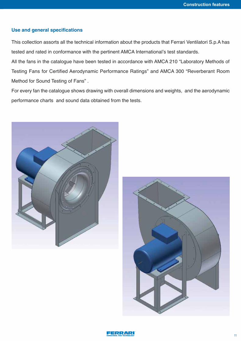
This collection assorts all the technical information about the products that Ferrari Ventilatori S.p.A has
tested and rated in conformance with the pertinent AMCA Internationalʼs test standards.
All the fans in the catalogue have been tested in accordance with AMCA 210 “Laboratory Methods of
Testing Fans for Certified Aerodynamic Performance Ratings” and AMCA 300 “Reverberant Room
Method for Sound Testing of Fans” .
For every fan the catalogue shows drawing with overall dimensions and weights, and the aerodynamic
performance charts and sound data obtained from the tests.
Use and general specifications
Construction features
NOTE:
12

CENTRIFUGAL FANS
OVERALL DIMENSIONS
• 3.- OVERALL DIMENSIONSART 406 . . . . . . . . . . . . . . . . . . . . . . . . . . . . . . . . . . . . . . . . . . . . . . . . . . . . . . . . . . . pag. 15ART 456 . . . . . . . . . . . . . . . . . . . . . . . . . . . . . . . . . . . . . . . . . . . . . . . . . . . . . . . . . . . pag. 15ART 567 . . . . . . . . . . . . . . . . . . . . . . . . . . . . . . . . . . . . . . . . . . . . . . . . . . . . . . . . . . . pag. 16
FI 506. . . . . . . . . . . . . . . . . . . . . . . . . . . . . . . . . . . . . . . . . . . . . . . . . . . . . . . . . . . . . pag. 16
FQ 356 . . . . . . . . . . . . . . . . . . . . . . . . . . . . . . . . . . . . . . . . . . . . . . . . . . . . . . . . . . . . pag. 17FQ 406 . . . . . . . . . . . . . . . . . . . . . . . . . . . . . . . . . . . . . . . . . . . . . . . . . . . . . . . . . . . . pag. 17FQ 456 . . . . . . . . . . . . . . . . . . . . . . . . . . . . . . . . . . . . . . . . . . . . . . . . . . . . . . . . . . . . pag. 18FQ 566 . . . . . . . . . . . . . . . . . . . . . . . . . . . . . . . . . . . . . . . . . . . . . . . . . . . . . . . . . . . . pag. 18
FR 457 . . . . . . . . . . . . . . . . . . . . . . . . . . . . . . . . . . . . . . . . . . . . . . . . . . . . . . . . . . . . pag. 19
15
Overall dimensions
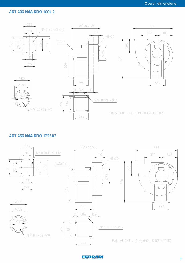
ART 406 N4A RDO 100L 2
ART 456 N4A RDO 132SA2

Overall dimensions
16
ART 567 N4A RDO 160M2
FI 506 N4A RDO 132SA2
17
Overall dimensions
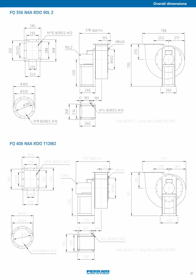
FQ 356 N4A RDO 90L 2
FQ 406 N4A RDO 112M2
Overall dimensions
18
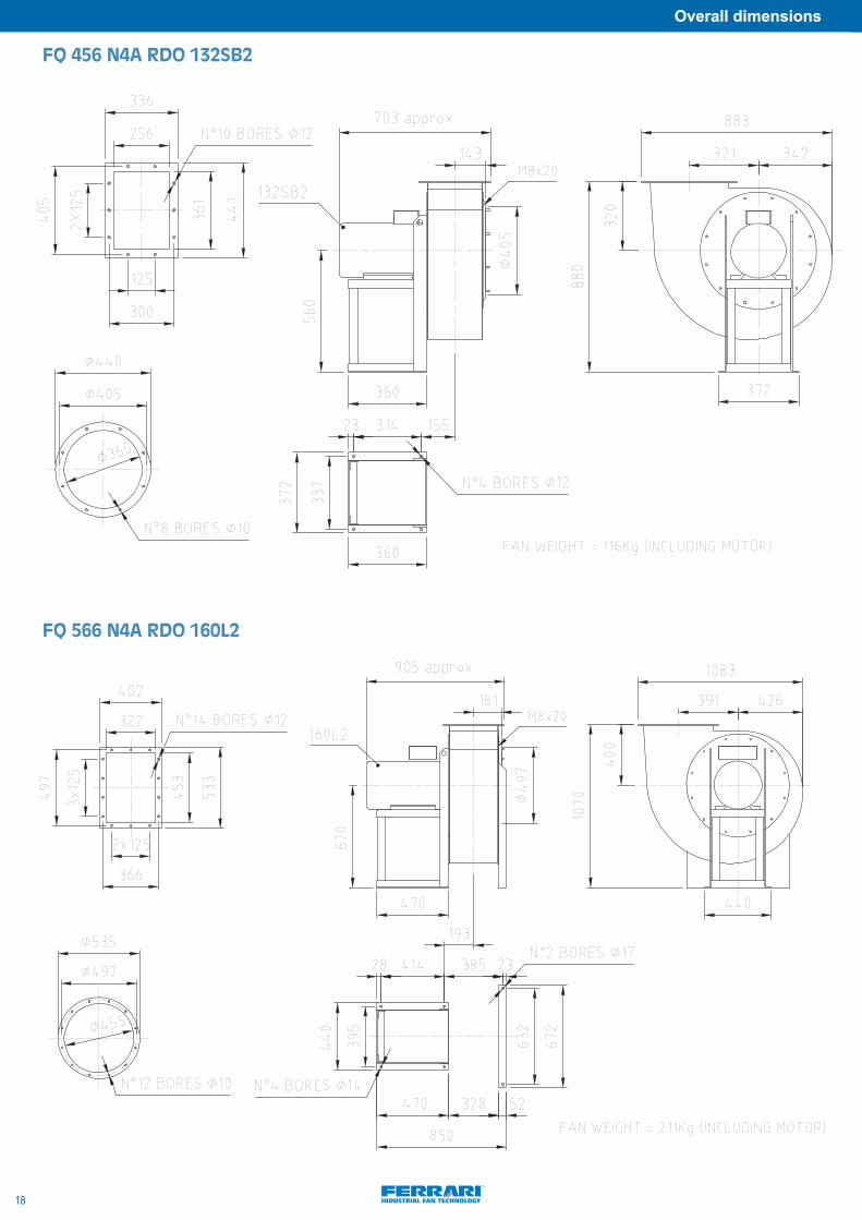
FQ 456 N4A RDO 132SB2
FQ 566 N4A RDO 160L2

NOTE:
19
Overall dimensions
FR 457 N4A RDO 132 MB2

Overall dimensions
NOTE:
20

CENTRIFUGAL FANS
PERFORMANCE CURVES AND NOISE DATA

• 4.- PERFORMANCE CURVES AND NOISE DATA . . . . . . . . . . . . . . . . . . . . . . . . . . . . . . . . . . . . . . . 1. Guide to curves . . . . . . . . . . . . . . . . . . . . . . . . . . . . . . . . . . . . . . . . . . . . . . . . .pag. 232. Performance curves and noise data
ART 406 . . . . . . . . . . . . . . . . . . . . . . . . . . . . . . . .pag. 24ART 456 . . . . . . . . . . . . . . . . . . . . . . . . . . . . . . . .pag. 25ART 567 . . . . . . . . . . . . . . . . . . . . . . . . . . . . . . . .pag. 26
FI 506 . . . . . . . . . . . . . . . . . . . . . . . . . . . . . . . .pag. 27
FQ 356 . . . . . . . . . . . . . . . . . . . . . . . . . . . . . . . .pag. 28FQ 406 . . . . . . . . . . . . . . . . . . . . . . . . . . . . . . . .pag. 29FQ 456 . . . . . . . . . . . . . . . . . . . . . . . . . . . . . . . .pag. 30FQ 566 . . . . . . . . . . . . . . . . . . . . . . . . . . . . . . . .pag. 31
FR 457 . . . . . . . . . . . . . . . . . . . . . . . . . . . . . . . .pag. 32

23
Performance curves and noise data
1. GUIDE TO CURVES
Performancecurves
Efficiency
Velocity
Rotationalspeed
Capacity
Powercurves
Pressureaxis
Dinamicpressure
Performance curveThis is the most representative curve of the fan. It shows the total pressure provided by the fan for a range of capacities. The point of intersection of thesystem curve and the performance curve determines the operating point of the fan. The curve doesnʼt cover the entire range from free delivery (no ob-struction to flow) to no delivery, but only the useful zone of the curve where the efficiency is higher. The selection of the fan shall assure that the operatingpoint of the fan lies in the useful zone. A fan working out of this zone could create instability or overheating of the motor drive. EfficiencyIt indicates the total efficiency of the fan represent the rate between the final energy received by the air and the energy supplied shaft of the fan. This effi-ciency reflects the losses into the fan but not the losses in the transmission and motor. Power curvesThose curves locate in the charts standardized motors power data. To know the absorbed power of a fan working point placed between two curves, inter-polation may be done. For a more precise value, the next formula can be use:
W= Absorbed power in kW Pt= total pressure in Pa, shown in the pressure axisV= Air delivered in m3/s, shown in the capacity axis ηt = Efficiency of the fan as read in the chart in %Since this absorbed power doesnʼt includes the transmission losses, so this power need to be increased by at least 15% before selecting the motor to beinstalled.
Example. The working point in the chart indicates a pressure of 420 Pa and a capacity of 8,75 m3/s. The efficiency shown is 71. The absorbed power isthen:
This absorbed power need to be increase by 15%, so the power to be considered for the selection of the motor would be: 5,17x1,15=5,95 Kw. So a motor5,5 kW power wonʼt be enough and a 7,5 Kw should be used.Rotational speedIt indicates the rotational speed of the impeller of the fan. Pressure AxisThe ordinate axis shows the total pressure provided by the fan. This pressure can be read both in Pa and kgf/m2 units. Capacity AxisThe first two abscissa axis show the capacity supplied by fan. In the first one expressed in m3/s, while in the second one in m3/h. The third and fourth axis present the dynamic pressure supplied by the fan in Pa and in kgf/m2 This dynamic pressure can be obtained using the formulaPd=ρ v2/2, where ρ is the density and v the velocity of the fluid.Last axis indicates the velocity of the fluid at inlet and outlet of the fan. This velocity is obtained by dividing the air delivered by the section of the fan.
W = V x Pt10 x ηt
W = V x Pt = 8,75 x 420 = 5,17 kW100 x ηt 10 x 71
Performance curves and noise data
24
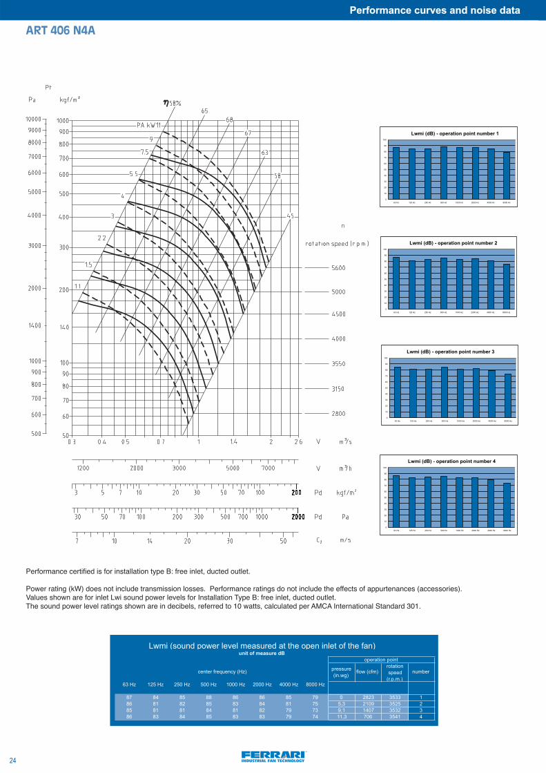
ART 406 N4A
pressure (in.wg)
flow (cfm)rotation speed
(r.p.m.)number
63 Hz 125 Hz 250 Hz 500 Hz 1000 Hz 2000 Hz 4000 Hz 8000 Hz
87 84 85 88 86 86 85 79 0 2823 3533 186 81 82 85 83 84 81 75 5,3 2109 3525 285 81 81 84 81 82 79 73 9,1 1407 3532 386 83 84 85 83 83 79 74 11,3 706 3541 4
center frequency (Hz)
Lwmi (sound power level measured at the open inlet of the fan)unit of measure dB
operation point
0
10
20
30
40
50
60
70
80
90
100
63 Hz 125 Hz 250 Hz 500 Hz 1000 Hz 2000 Hz 4000 Hz 8000 Hz
Lwmi (dB) - operation point number 1
0
10
20
30
40
50
60
70
80
90
100
63 Hz 125 Hz 250 Hz 500 Hz 1000 Hz 2000 Hz 4000 Hz 8000 Hz
Lwmi (dB) - operation point number 2
0
10
20
30
40
50
60
70
80
90
100
63 Hz 125 Hz 250 Hz 500 Hz 1000 Hz 2000 Hz 4000 Hz 8000 Hz
Lwmi (dB) - operation point number 3
0
10
20
30
40
50
60
70
80
90
100
63 Hz 125 Hz 250 Hz 500 Hz 1000 Hz 2000 Hz 4000 Hz 8000 Hz
Lwmi (dB) - operation point number 4
Lwmi (dB) - operation point number 1
Lwmi (dB) - operation point number 2
Lwmi (dB) - operation point number 3
Lwmi (dB) - operation point number 4
Performance certified is for installation type B: free inlet, ducted outlet.
Power rating (kW) does not include transmission losses. Performance ratings do not include the effects of appurtenances (accessories).Values shown are for inlet Lwi sound power levels for Installation Type B: free inlet, ducted outlet.The sound power level ratings shown are in decibels, referred to 10 watts, calculated per AMCA International Standard 301.
25
Performance curves and noise data
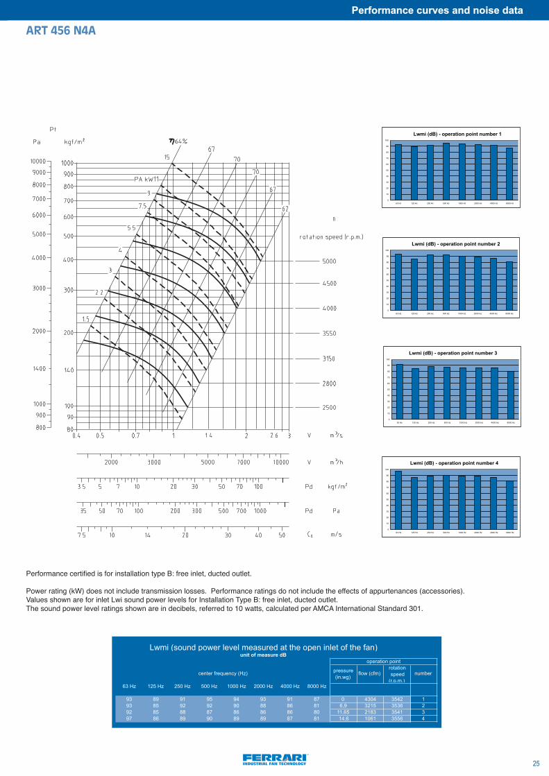
ART 456 N4A
pressure (in.wg)
flow (cfm)rotation speed
(r.p.m.)number
63 Hz 125 Hz 250 Hz 500 Hz 1000 Hz 2000 Hz 4000 Hz 8000 Hz
93 89 91 95 94 93 91 87 0 4304 3542 193 85 92 92 90 88 86 81 6,9 3215 3536 292 85 88 87 86 86 86 80 11,65 2183 3541 397 86 89 90 89 89 87 81 14,6 1061 3556 4
center frequency (Hz)
Lwmi (sound power level measured at the open inlet of the fan)unit of measure dB
operation point
0
10
20
30
40
50
60
70
80
90
100
63 Hz 125 Hz 250 Hz 500 Hz 1000 Hz 2000 Hz 4000 Hz 8000 Hz
Lwmi (dB) - operation point number 1
0
10
20
30
40
50
60
70
80
90
100
63 Hz 125 Hz 250 Hz 500 Hz 1000 Hz 2000 Hz 4000 Hz 8000 Hz
Lwmi (dB) - operation point number 2
0
10
20
30
40
50
60
70
80
90
100
63 Hz 125 Hz 250 Hz 500 Hz 1000 Hz 2000 Hz 4000 Hz 8000 Hz
Lwmi (dB) - operation point number 3
0
10
20
30
40
50
60
70
80
90
100
63 Hz 125 Hz 250 Hz 500 Hz 1000 Hz 2000 Hz 4000 Hz 8000 Hz
Lwmi (dB) - operation point number 4
Lwmi (dB) - operation point number 1
Lwmi (dB) - operation point number 2
Lwmi (dB) - operation point number 3
Lwmi (dB) - operation point number 4
Performance certified is for installation type B: free inlet, ducted outlet.
Power rating (kW) does not include transmission losses. Performance ratings do not include the effects of appurtenances (accessories).Values shown are for inlet Lwi sound power levels for Installation Type B: free inlet, ducted outlet.The sound power level ratings shown are in decibels, referred to 10 watts, calculated per AMCA International Standard 301.
Performance curves and noise data
26
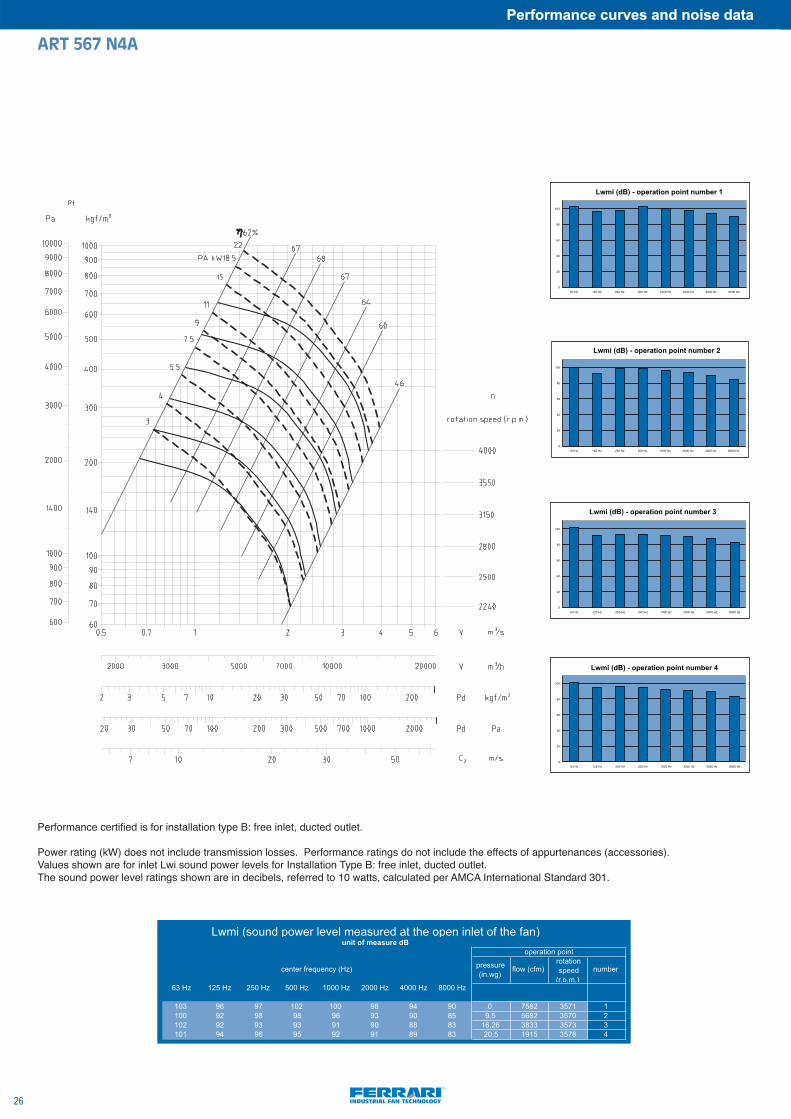
ART 567 N4A
pressure (in.wg)
flow (cfm)rotation speed
(r.p.m.)number
63 Hz 125 Hz 250 Hz 500 Hz 1000 Hz 2000 Hz 4000 Hz 8000 Hz
103 96 97 102 100 98 94 90 0 7582 3571 1100 92 98 98 96 93 90 85 9,5 5682 3570 2102 92 93 93 91 90 88 83 16,26 3833 3573 3101 94 96 95 92 91 89 83 20,5 1915 3578 4
center frequency (Hz)
Lwmi (sound power level measured at the open inlet of the fan)unit of measure dB
operation point
0
20
40
60
80
100
63 Hz 125 Hz 250 Hz 500 Hz 1000 Hz 2000 Hz 4000 Hz 8000 Hz
Lwmi (dB) - operation point number 1
0
20
40
60
80
100
63 Hz 125 Hz 250 Hz 500 Hz 1000 Hz 2000 Hz 4000 Hz 8000 Hz
Lwmi (dB) - operation point number 2
0
20
40
60
80
100
63 Hz 125 Hz 250 Hz 500 Hz 1000 Hz 2000 Hz 4000 Hz 8000 Hz
Lwmi (dB) - operation point number 3
0
20
40
60
80
100
63 Hz 125 Hz 250 Hz 500 Hz 1000 Hz 2000 Hz 4000 Hz 8000 Hz
Lwmi (dB) - operation point number 4
Lwmi (dB) - operation point number 1
Lwmi (dB) - operation point number 2
Lwmi (dB) - operation point number 3
Lwmi (dB) - operation point number 4
Performance certified is for installation type B: free inlet, ducted outlet.
Power rating (kW) does not include transmission losses. Performance ratings do not include the effects of appurtenances (accessories).Values shown are for inlet Lwi sound power levels for Installation Type B: free inlet, ducted outlet.The sound power level ratings shown are in decibels, referred to 10 watts, calculated per AMCA International Standard 301.

27
Performance curves and noise data
FI 506 N4A
pressure (in.wg)
flow (cfm)rotation speed
(r.p.m.)number
63 Hz 125 Hz 250 Hz 500 Hz 1000 Hz 2000 Hz 4000 Hz 8000 Hz
93 87 89 90 91 90 90 96 0 3670 3537 193 85 89 91 91 90 90 87 7,8 2754 3526 294 84 89 92 90 89 88 80 15,4 1830 3530 393 84 91 93 92 90 87 80 18,03 905 3541 4
center frequency (Hz)
Lwmi (sound power level measured at the open inlet of the fan)unit of measure dB
operation point
0
10
20
30
40
50
60
70
80
90
100
63 Hz 125 Hz 250 Hz 500 Hz 1000 Hz 2000 Hz 4000 Hz 8000 Hz
Lwmi (dB) - operation point number 1
0
10
20
30
40
50
60
70
80
90
100
63 Hz 125 Hz 250 Hz 500 Hz 1000 Hz 2000 Hz 4000 Hz 8000 Hz
Lwmi (dB) - operation point number 2
0
10
20
30
40
50
60
70
80
90
100
63 Hz 125 Hz 250 Hz 500 Hz 1000 Hz 2000 Hz 4000 Hz 8000 Hz
Lwmi (dB) - operation point number 3
0
10
20
30
40
50
60
70
80
90
100
63 Hz 125 Hz 250 Hz 500 Hz 1000 Hz 2000 Hz 4000 Hz 8000 Hz
Lwmi (dB) - operation point number 4
Lwmi (dB) - operation point number 1
Lwmi (dB) - operation point number 2
Lwmi (dB) - operation point number 3
Lwmi (dB) - operation point number 4
Performance certified is for installation type B: free inlet, ducted outlet.
Power rating (kW) does not include transmission losses. Performance ratings do not include the effects of appurtenances (accessories).Values shown are for inlet Lwi sound power levels for Installation Type B: free inlet, ducted outlet.The sound power level ratings shown are in decibels, referred to 10 watts, calculated per AMCA International Standard 301.

Performance curves and noise data
28
FQ 356 N4A
pressure (in.wg) flow (cfm)
rotation speed (r.p.m.)
number
63 Hz 125 Hz 250 Hz 500 Hz 1000 Hz 2000 Hz 4000 Hz 8000 Hz
90 84 82 88 85 84 83 81 0 2790 3554 187 81 80 84 83 80 79 73 3,25 2076 3544 287 81 82 83 81 79 78 71 6 1391 3542 388 85 89 87 83 82 81 73 7,4 685 3552 4
Lwmi (sound power level measured at the open inlet of the fan)unit of measure dB
operation point
center frequency (Hz)
0
10
20
30
40
50
60
70
80
90
100
63 Hz 125 Hz 250 Hz 500 Hz 1000 Hz 2000 Hz 4000 Hz 8000 Hz
Lwmi (dB) - operation point number 1
0
10
20
30
40
50
60
70
80
90
100
63 Hz 125 Hz 250 Hz 500 Hz 1000 Hz 2000 Hz 4000 Hz 8000 Hz
Lwmi (dB) - operation point number 2
0
10
20
30
40
50
60
70
80
90
100
63 Hz 125 Hz 250 Hz 500 Hz 1000 Hz 2000 Hz 4000 Hz 8000 Hz
Lwmi (dB) - operation point number 3
30
40
50
60
70
80
90
100
Lwmi (dB) - operation point number 4
0
10
63 Hz 125 Hz 250 Hz 500 Hz 1000 Hz 2000 Hz 4000 Hz 8000 Hz
20
Lwmi (dB) - operation point number 1
Lwmi (dB) - operation point number 2
Lwmi (dB) - operation point number 3
Lwmi (dB) - operation point number 4
Performance certified is for installation type B: free inlet, ducted outlet.
Power rating (kW) does not include transmission losses. Performance ratings do not include the effects of appurtenances (accessories).Values shown are for inlet Lwi sound power levels for Installation Type B: free inlet, ducted outlet.The sound power level ratings shown are in decibels, referred to 10 watts, calculated per AMCA International Standard 301.
29
Performance curves and noise data
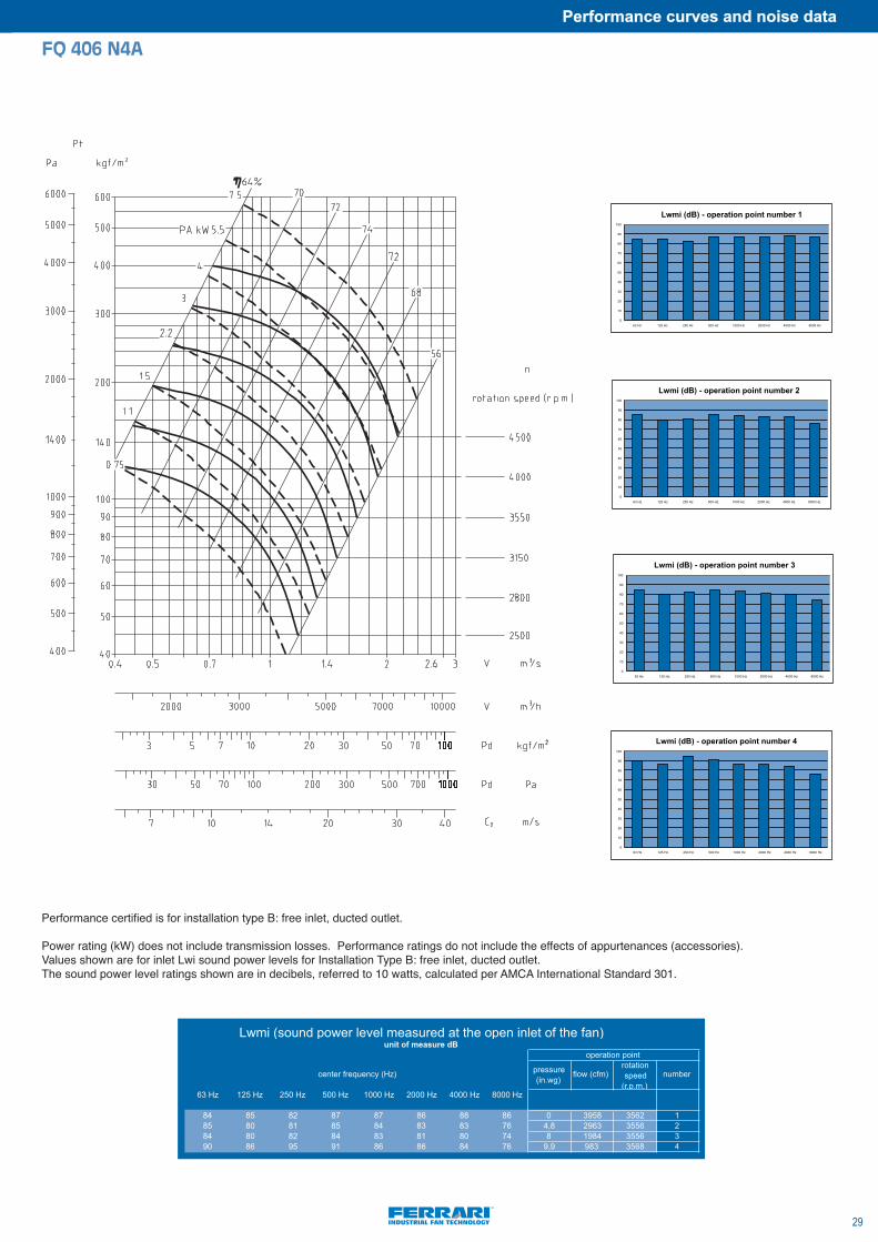
FQ 406 N4A
pressure (in.wg)
flow (cfm)rotation speed
(r.p.m.)number
63 Hz 125 Hz 250 Hz 500 Hz 1000 Hz 2000 Hz 4000 Hz 8000 Hz
84 85 82 87 87 86 88 86 0 3958 3562 185 80 81 85 84 83 83 76 4,8 2963 3556 284 80 82 84 83 81 80 74 8 1984 3556 390 86 95 91 86 86 84 76 9,9 983 3568 4
center frequency (Hz)
Lwmi (sound power level measured at the open inlet of the fan)unit of measure dB
operation point
0
10
20
30
40
50
60
70
80
90
100
63 Hz 125 Hz 250 Hz 500 Hz 1000 Hz 2000 Hz 4000 Hz 8000 Hz
Lwmi (dB) - operation point number 1
0
10
20
30
40
50
60
70
80
90
100
63 Hz 125 Hz 250 Hz 500 Hz 1000 Hz 2000 Hz 4000 Hz 8000 Hz
Lwmi (dB) - operation point number 2
0
10
20
30
40
50
60
70
80
90
100
63 Hz 125 Hz 250 Hz 500 Hz 1000 Hz 2000 Hz 4000 Hz 8000 Hz
Lwmi (dB) - operation point number 3
0
10
20
30
40
50
60
70
80
90
100
63 Hz 125 Hz 250 Hz 500 Hz 1000 Hz 2000 Hz 4000 Hz 8000 Hz
Lwmi (dB) - operation point number 4
Lwmi (dB) - operation point number 1
Lwmi (dB) - operation point number 2
Lwmi (dB) - operation point number 3
Lwmi (dB) - operation point number 4
Performance certified is for installation type B: free inlet, ducted outlet.
Power rating (kW) does not include transmission losses. Performance ratings do not include the effects of appurtenances (accessories).Values shown are for inlet Lwi sound power levels for Installation Type B: free inlet, ducted outlet.The sound power level ratings shown are in decibels, referred to 10 watts, calculated per AMCA International Standard 301.
Performance curves and noise data
30
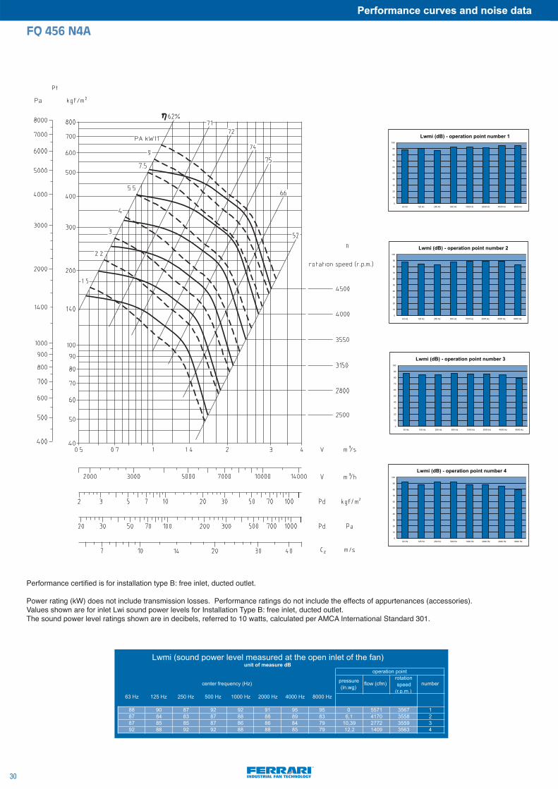
FQ 456 N4A
pressure (in.wg)
flow (cfm)rotation speed
(r.p.m.)number
63 Hz 125 Hz 250 Hz 500 Hz 1000 Hz 2000 Hz 4000 Hz 8000 Hz
88 90 87 92 92 91 95 95 0 5571 3567 187 84 83 87 88 88 89 83 6,1 4170 3558 287 85 85 87 86 86 84 79 10,39 2772 3559 392 88 92 92 88 88 85 79 12,2 1409 3563 4
center frequency (Hz)
Lwmi (sound power level measured at the open inlet of the fan)unit of measure dB
operation point
0
10
20
30
40
50
60
70
80
90
100
63 Hz 125 Hz 250 Hz 500 Hz 1000 Hz 2000 Hz 4000 Hz 8000 Hz
Lwmi (dB) - operation point number 1
0
10
20
30
40
50
60
70
80
90
100
63 Hz 125 Hz 250 Hz 500 Hz 1000 Hz 2000 Hz 4000 Hz 8000 Hz
Lwmi (dB) - operation point number 2
0
10
20
30
40
50
60
70
80
90
100
63 Hz 125 Hz 250 Hz 500 Hz 1000 Hz 2000 Hz 4000 Hz 8000 Hz
Lwmi (dB) - operation point number 3
0
10
20
30
40
50
60
70
80
90
100
63 Hz 125 Hz 250 Hz 500 Hz 1000 Hz 2000 Hz 4000 Hz 8000 Hz
Lwmi (dB) - operation point number 4
Lwmi (dB) - operation point number 1
Lwmi (dB) - operation point number 2
Lwmi (dB) - operation point number 3
Lwmi (dB) - operation point number 4
Performance certified is for installation type B: free inlet, ducted outlet.
Power rating (kW) does not include transmission losses. Performance ratings do not include the effects of appurtenances (accessories).Values shown are for inlet Lwi sound power levels for Installation Type B: free inlet, ducted outlet.The sound power level ratings shown are in decibels, referred to 10 watts, calculated per AMCA International Standard 301.

31
Performance curves and noise data
FQ 566 N4A
pressure (in.wg)
flow (cfm)rotation speed
(r.p.m.)number
63 Hz 125 Hz 250 Hz 500 Hz 1000 Hz 2000 Hz 4000 Hz 8000 Hz
94 94 95 98 100 99 100 102 0 11161 3577 195 91 91 95 97 95 94 90 10,25 8323 3570 295 94 97 94 94 93 90 86 15,75 5616 3570 397 97 102 98 94 94 92 89 19 2811 3574 4
center frequency (Hz)
Lwmi (sound power level measured at the open inlet of the fan)unit of measure dB
operation point
0
20
40
60
80
100
63 Hz 125 Hz 250 Hz 500 Hz 1000 Hz 2000 Hz 4000 Hz 8000 Hz
Lwmi (dB) - operation point number 1
0
20
40
60
80
100
63 Hz 125 Hz 250 Hz 500 Hz 1000 Hz 2000 Hz 4000 Hz 8000 Hz
Lwmi (dB) - operation point number 2
0
20
40
60
80
100
63 Hz 125 Hz 250 Hz 500 Hz 1000 Hz 2000 Hz 4000 Hz 8000 Hz
Lwmi (dB) - operation point number 3
0
20
40
60
80
100
63 Hz 125 Hz 250 Hz 500 Hz 1000 Hz 2000 Hz 4000 Hz 8000 Hz
Lwmi (dB) - operation point number 4
Lwmi (dB) - operation point number 1
Lwmi (dB) - operation point number 2
Lwmi (dB) - operation point number 3
Lwmi (dB) - operation point number 4
Performance certified is for installation type B: free inlet, ducted outlet.
Power rating (kW) does not include transmission losses. Performance ratings do not include the effects of appurtenances (accessories).Values shown are for inlet Lwi sound power levels for Installation Type B: free inlet, ducted outlet.The sound power level ratings shown are in decibels, referred to 10 watts, calculated per AMCA International Standard 301.

Performance curves and noise data
32
FR 457 N4A
pressure (in.wg) flow (cfm)
rotation speed
(r.p.m.)number
63 Hz 125 Hz 250 Hz 500 Hz 1000 Hz 2000 Hz 4000 Hz 8000 Hz
93 98 92 94 101 100 97 98 0 8927 3518 190 94 90 92 96 97 93 91 6,3 6624 3500 289 92 90 90 94 95 90 84 10,4 4449 3500 393 96 96 97 94 93 88 82 14,15 2237 3520 4
center frequency (Hz)
Lwmi (sound power level measured at the open inlet of the fan)unit of measure dB
operation point
0
20
40
60
80
100
63 Hz 125 Hz 250 Hz 500 Hz 1000 Hz 2000 Hz 4000 Hz 8000 Hz
Lwmi (dB) - operation point number 1
0
10
20
30
40
50
60
70
80
90
100
63 Hz 125 Hz 250 Hz 500 Hz 1000 Hz 2000 Hz 4000 Hz 8000 Hz
Lwmi (dB) - operation point number 2
0
10
20
30
40
50
60
70
80
90
100
63 Hz 125 Hz 250 Hz 500 Hz 1000 Hz 2000 Hz 4000 Hz 8000 Hz
Lwmi (dB) - operation point number 3
0
20
40
60
80
100
120
63 Hz 125 Hz 250 Hz 500 Hz 1000 Hz 2000 Hz 4000 Hz 8000 Hz
Lwmi (dB) - operation point number 4
Lwmi (dB) - operation point number 1
Lwmi (dB) - operation point number 2
Lwmi (dB) - operation point number 3
Lwmi (dB) - operation point number 4
Performance certified is for installation type B: free inlet, ducted outlet.
Power rating (kW) does not include transmission losses. Performance ratings do not include the effects of appurtenances (accessories).Values shown are for inlet Lwi sound power levels for Installation Type B: free inlet, ducted outlet.The sound power level ratings shown are in decibels, referred to 10 watts, calculated per AMCA International Standard 301.

CENTRIFUGAL FANS
ACCESSORIES

ACCESSORIES1. - Stabilizers for antivibration mounts . . . . . . . . . . . . . . . . . . . . . . . . . . . . . .pag. 352. - Antivibration mounts . . . . . . . . . . . . . . . . . . . . . . . . . . . . . . . . . . . . . . . . . . .pag. 363. - Fixing plates . . . . . . . . . . . . . . . . . . . . . . . . . . . . . . . . . . . . . . . . . . . . . . . . . . .pag. 36
35
Accessories
FAN TYPE
FQ 356
ART 406
FQ 406
ART 456FI 506FQ 456FR 457
BOLTMOTOR SIZE
M8x20
M10x25
M10x25
90
100
112
M10x25132
FIG.
1
2
3
4
1. STABILIZERS FOR ANTIVIBRATION MOUNTSUse: when AVMS are required this accessory helps to stabilize the whole fan structure.
FIG. 1
FIG. 2
FIG. 3
FIG. 4

Accessories
36
TYPELoad for 4 supports
Kgb h Ø l i
Weight
Kg
AM25 41÷80 25 20 M6 16 5 0,03
AM30 81÷140 30 30 M8 20 6 0,05AM40 141÷224 40 30 M8 23 6 0,1AM50 225÷315 50 40 M10 28 7 0,2
FAN TYPE N° AVMS TYPE
ART 406
ART 456
ART 457FI 506
FQ 356
AM 30
AM 30
AM 30AM 30
AM 25
4
4
44
4
FAN TYPE N° AVMS TYPE
FQ 406
FQ 456
FQ 566FR 457
AM 30
AM 30
AM 50AM 30
4
4
44
PLATE A/V MOUNTS A B C D E I M S
PT 20/25
PT 30/40
PT 50
AM 20/25
AM 30/40
AM 50
40
40
75
95
95
135
11
12
16
8
8
10
12,5
12,5
15
70
70
105
6
8
10
6
6
8
2. ANTIVIBRATION MOUNTSUse: they are used to avoid the transmission of noise and vibrations.They are of special metal-rubber. Working temperature - 20 °C + 60 °C.
3. FIXING PLATESUse: they are used to connect the AVMSto the ground.
NOTE:
37
Accessories

NOTE:
Accessories
38


F.lli Ferrari Ventilatori Industriali S.p.A.
Via Marchetti, 28 36071 Arzignano (VI)Tel +39 0444 471100 Fax +39 0444 [email protected]
www.ferrariventilatori.com
Febr
uary
201
0