*0 f. 1chwrin - defense technical information center · this data shows the amplitude and phase...
TRANSCRIPT
Research and Development Technical Report
ECOM-4357
•---" ROTOR BLADE EFFECTS ON L-BAND S IGNALS RECEIVED BY[•.: HELICOPTER ANTENNAS MOUNTED ABOVE THE ROTOR BLADE:g," CW EXPERIMENTS
°•,!i, •"C. M. DeSantisSF. Schwering
,- • Communications/Automatic Data Processing Laboratory
0r
C. .. e ati
• .,,Lj:- .October 1.975 ....:-
*0 F. 1chwrin
,:L • O DISTR IBUTION STATZMENT ,.Sa CoApproves for pubitc release; ..,
.. ' • distribution unlimited.."
SECOM
•;•.. US ARMY ELECTRONICS COMMAND FORT MONMOUTH, NEW JERSEY 07703
•"•,i' 0
L•*
*L

r,..
I Disclaimers
The findings in this report are not to be construed as anofficial Department of the Army position, unless so desig-nated by other authoriyed documents.
The citation of trade names and names of manufacturers inthis report is not to be construed as official Governmentindorsement or approval of commercial products or servicesreferenced herein.
Disposition
Destroy this report when it is no longer rteeded. Do notreturn it to the originator.
- ;2
rI
• a.. ...... • t... . .',. &..,.>, . -_. . . . ' : • • • • •• .

4A
UNCLASSIFTEDSECURITY CLASSIFICATION rOF THiS PAGE tMhon Date Ifntateit)
REPORT DOCUMENTATION PAGE ___
EPL2.GOVT ACCGSION NO. 3 .RLý-
-IECdM- 30'it¶ T LEwd~bttl.~flOR .AE LFFECTS ON J.-"AM10
/5JGNALS RFCCIVED WBYELUICPER AN4TENNAS M0UNTED1 t ¶A8OVE THt ROTOR BLADt: CW EXPERtNENTS._____
7. A'1TtOR~a) 8. COP4TP A T-7.' ,',A _NT u4E_.H_
M.C t Santis m F chwering
11. PERFORMING ORGANIZATION NAý41E AND ADURESS .'1-0. -7pad4- ----
Comnumnications/Automatic Data Proc.,Lab.LAMSEL-NL-RH lf ,m,ýLFort Monmouth, New Jersey 07703 ______ . - -
11. CONTROLLING OFFICE NAME AND ADDRESS LZ.ASK *T OA'rr-4
Commiunications/Automatic Data Processing Lab. iU. S. Army Electronics Cormmand 13.NMEOFrVE'Fort._Monmouth,_N._J._07703 1113__
14. MONITORING AGENCY NAME & AOORESS(il different from Controllfing Office) IS. SECUR-'. ... .' N
UNCLSFTFED
F16. D(STRiBUT!ON STAtEMENT (of thg. heport)~I 1
Aproedfor public release; diht4ribution unlimited.....-
1. DISTRIBUTION STATEMENT (of the abaitrael entered in Block 20. 111 difierent train Report)
WS SUPPLEMENTARY NOTES
19. K(EY WONr*- ... re.verse aide it necensat- and identity by blockt n imber.
Rotor moduldtion; L-band navigation system;
Helicopter antennas; Shielding effect of rotor.
20 A664ACT (Continue an reverse. aide It neeoaaary end Ident~ity by block number)
Rotor effects on L-Band signals received by helicopter antennas havebeen examined experimentally. CW data for two receiving-antenna locations
- .above the rotor blade, viz, at the turning axis of the blade aid on thie tai ¶is presented. This data shows the amplitude and phase variations to be exj~--:ted as a function of the direction of the incident signal. The effects ofcounterpoise size and height above the main rotor are also studied . T nit is shown that the signal variations were typically <ýS3 6B for po]Iýr *.r:-
DDO I '" 1473 EDITION OF I NOV 635 ISO9SOLETr NLSJ :
SIECURITY CLASSIFICATION OF THIS" %,; (',n f¶-"'

IM ASFTM.-9cuPVIY CLASSIPICATION OP THIS PAMw Doe 8nra,_,.M
of arrival e ý700; but that for.qreater angles, the signal amplitude changesby as much as ± 7 dB. For 9> go•(an arrival angle obtained, for instance,during a turning and banking ftaeuver) signal levels can decrease by -15 dBand the phase variat-'on can exceed 1800. The tail location appears to be abetter choice for the antenna than the center location. A worst-case analysisof CW rotor effects is presented in Appendix I. Appendices II and III containsome of the data measured at both antenna locations and should be referred tofor a better understanding of the signal variations involved.
UNCLASSIFIED$ECURITY CLASSIFICATION OF THIS PAGEf'Ihsm DOIa tntem,.
L
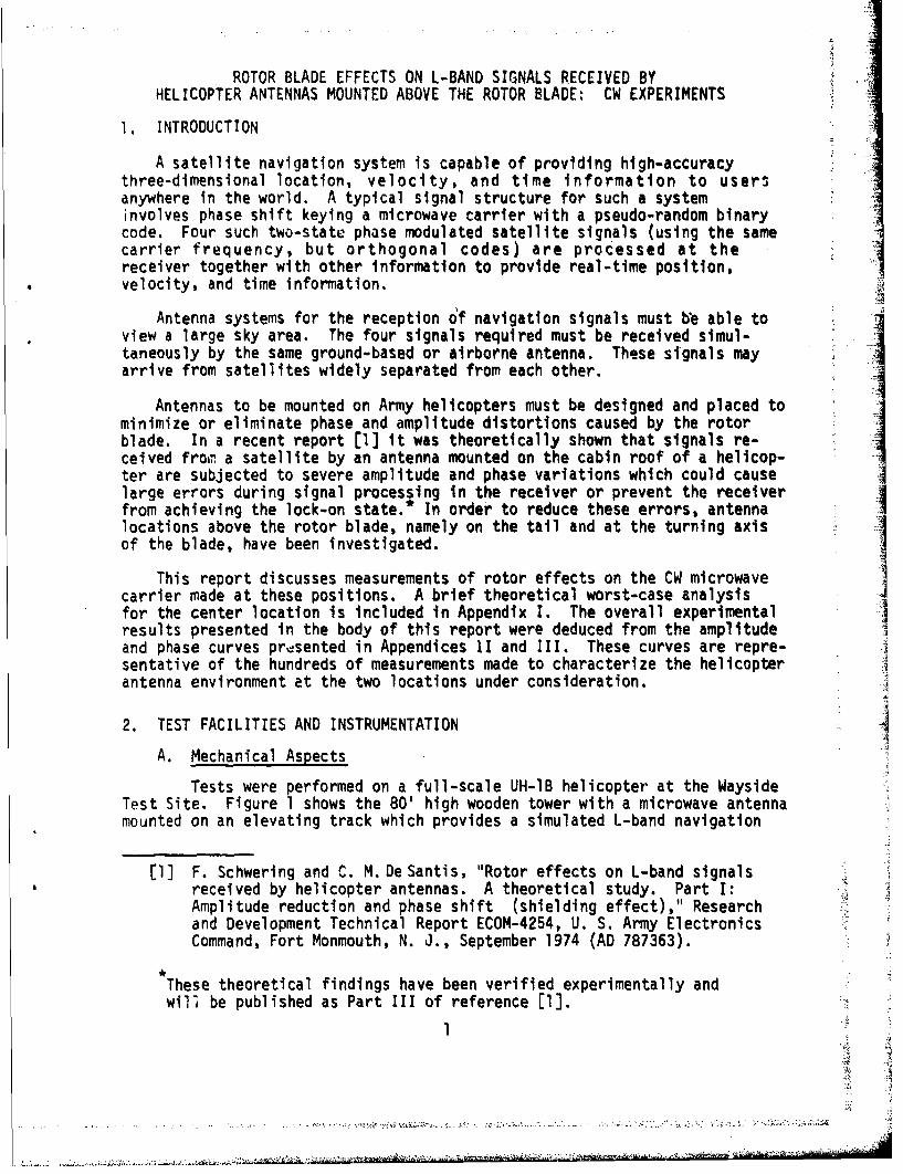
CONTENTS
Pagie
INTRODUCTION 1
TEST FACILITIES AND INSTRUMENTATION 1
A., Mechanical Aspects 1
B. Electrical Aspects 2 I
C. Receiving Antenna and Mounting 2
3. TEST RESULTS 2
A. Test Series 2
B. Amplitude Variations 3
C. Phase Variations 3
4. DATA ANALYSIS 6
5. CONCLUSIONS 7
ACKNOWLEDGMENTS 7
APPENDICES
I. WORST-CASE ANALYSIS OF ROTOR-BLADE EFFECTS ON 21ANTENNAS MOUNTED ABOVE THE ROTOR AT THE TURNING AXIS
11. EXPERIMENTAL DATA CHARACTERIZING THE SIGNAL 28FLUCTUATIONS AT THE CENTER LOCATION ABOVE THE ROTOR
II1. SELECTED EXPERIMENTAL DATA CHARACTERIZING THE SIGNAL 74
FLUCTUATIONS AT THE TAIL ABOVE THE ROTOR
TABLES
I. Azimuth and Polar Angles Considered for CW Rotor 4Blade Modulation Tests; Antenna at Center Position
II. Azimuth and Polar Angles Considered for CW Rotor 5Blade Modulation Tests; Antenna on Tail
FIGURES
"Figures 1 to 12 8 - 20
Figures 1-1 to 1-4 24 27
Figures II-1 to 11-44 30 73
Figures III-I to 111-38 76 -113 .3'
. ............ . .-.
ROTOR BLADE EFFECTS ON L-BAND SIGNALS RECEIVED BY
HELICOPTER ANTENNAS MOUNTED ABOVE THE ROTOR BLADE: CW EXPERIMENTS
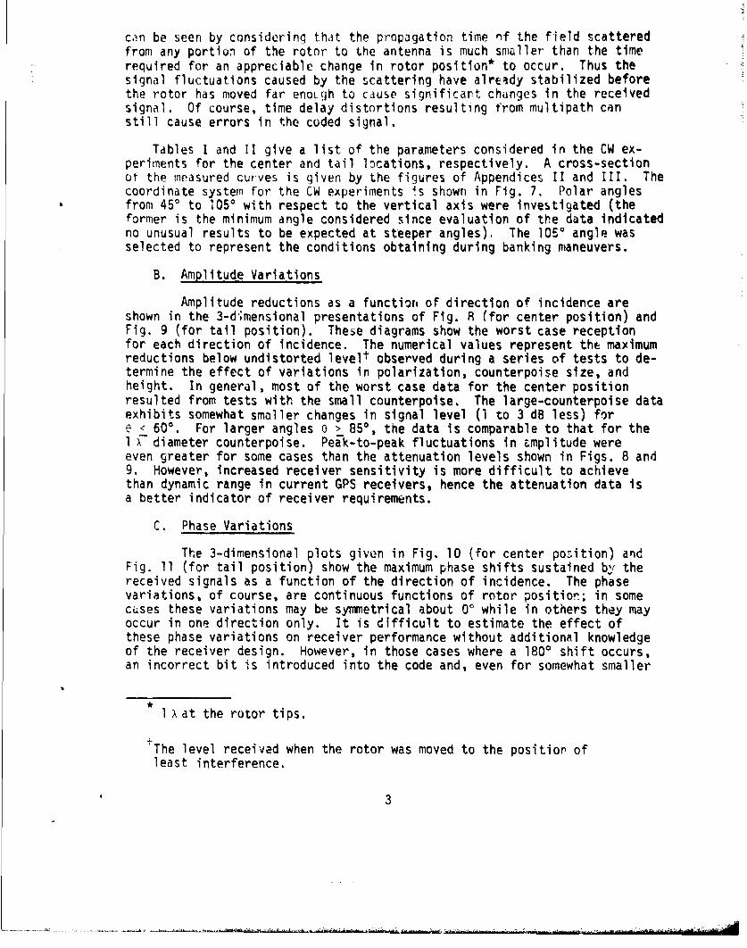
1. INTRODUCTION
A satellite navigation system is capable of providing high-accuracythree-dimensional location, velocity, and time Information to usersanywhere in the world. A typical signal structure for such a systeminvolves phase shift keying a microwave carrier with a pseudo-random binarycode. Four such two-state phase modulated satellite signals (using the samecarrier frequency, but orthogonal codes) are processed at thereceiver together with other information to provide real-time position,velocity, and time information.
Antenna systems for the reception of navigation signals must be able toview a large sky area. The four signals required must be received simul-taneously by the same ground-based or airborne antenna. These signals mayarrive from satellites widely separated from each other.
Antennas to be mounted on Army helicopters must be designed and placed tominimize or eliminate phase and amplitude distortions caused by the rotorblade. In a recent report [1] it was theoretically shown that signals re-ceived froo. a satellite by an antenna mounted on the cabin roof of a helicop-ter are subjected to severe amplitude and phase variations which could causelarge errors during signal processing in the receiver or prevent the receiverfrom achieving the lock-on state.* In order to reduce these errors, antennalocations above the rotor blade, namely on the tail and at the turning axisof the blade, have been investigated.
This report discusses measurements of rotor effects on the CW microwavecarrier made at these positions. A brief theoretical worst-case analysisfor the center location is included in Appendix I. The overall experimentalresults presented in the body of this report were deduced from the amplitudeand phase curves prdsented in Appendices 1I and III. These curves are repre-sentative of the hundreds of measurements made to characterize the helicopterantenna environment at the two locations under consideration.
2. TEST FACILITIES AND INSTRUMENTATION -.
A. Mechanical Aspects
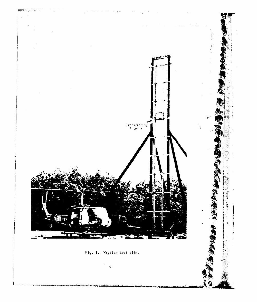
Tests were performed on a full-scale UH-lB helicopter at the WaysideTest Site. Figure 1 shows the 80' high wooden tower with a microwave antennamounted on an elevating track which provides a simulated L-band navigation
[1] F. Schwerlng and C. M. De Santis, "Rotor effects on L-band signalsreceived by helicopter antennas. A theoretical study. Part I:Amplitude reduction and phase shift (shielding effect)," Researchand Development Technical Report ECOM-4254, U. S. Army ElectronicsCommand, Fort Monmouth, N. J., September 1974 (AD 787363).
These theoretical findings have been verified experimentally andwill be published as Part III of reference [l].
1C
: -- -

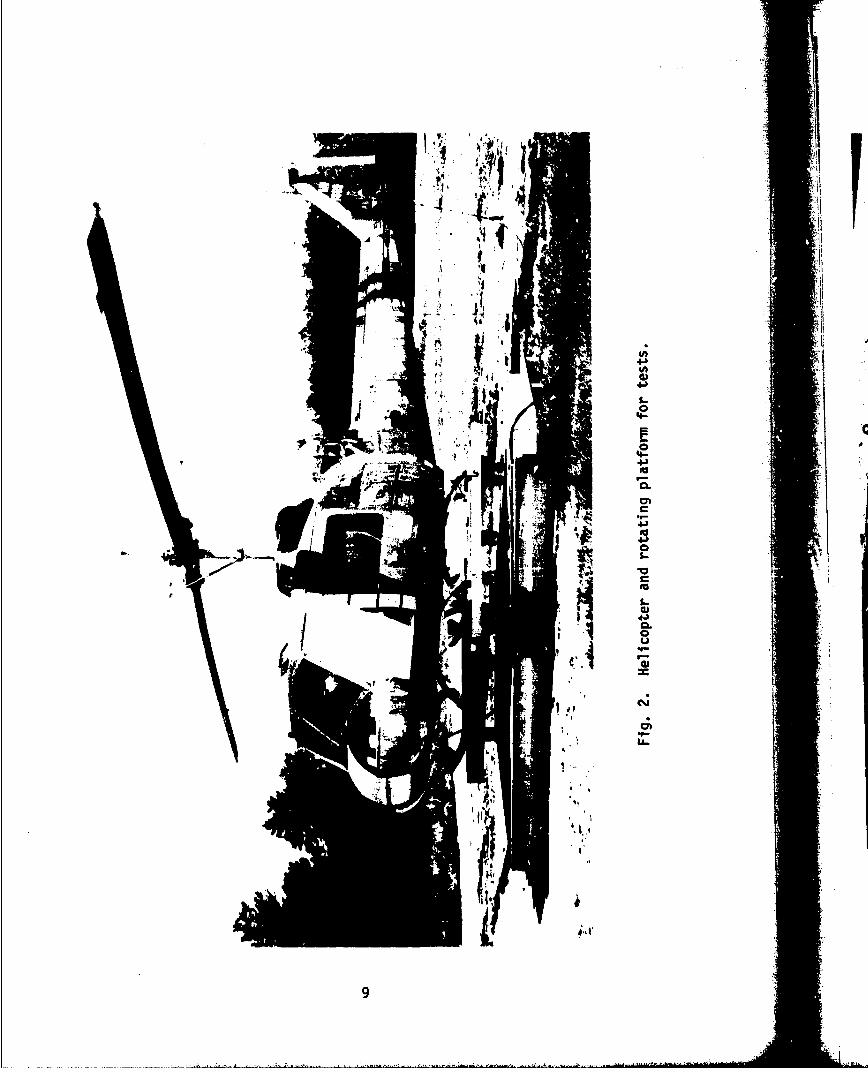
signal arriving at a selected polar angle and polarization. The helicopterrests on a rotating platform which permits azimuth angle variation (seeFig. 2). The rotor blade of this helicopter is rotated by a slow-speedsynchro-positioner which drives the recording equipment inside the cabin andthereby provides received signal information as a function of instantaneousrotor position. The helicopter used is a non-operational UH-IB, strippedinside to provide room for the instrumentation and operators.
B. Electrical Aspects
The transmitting and receiving equipment were located inside thehelicopter (see Fig. 3). The CW transmitter signal is split by means of adirect';onal coupler: one branch feeds the transmitting antenna on the towervia a coaxial cable (ý = %120 ft.) and the other branch feeds the receiveras the reference signal. The phase and frequency locked receiver measuresthe a'rPFi'iude and phase of a test signal as a function of this referencesignal. Outputs from the receiver drive a 2-channel strip chart recorder, andthus provide ampl 4tude and phase curves as a function of rotor position.
C. Receiving Antenna and Mounting
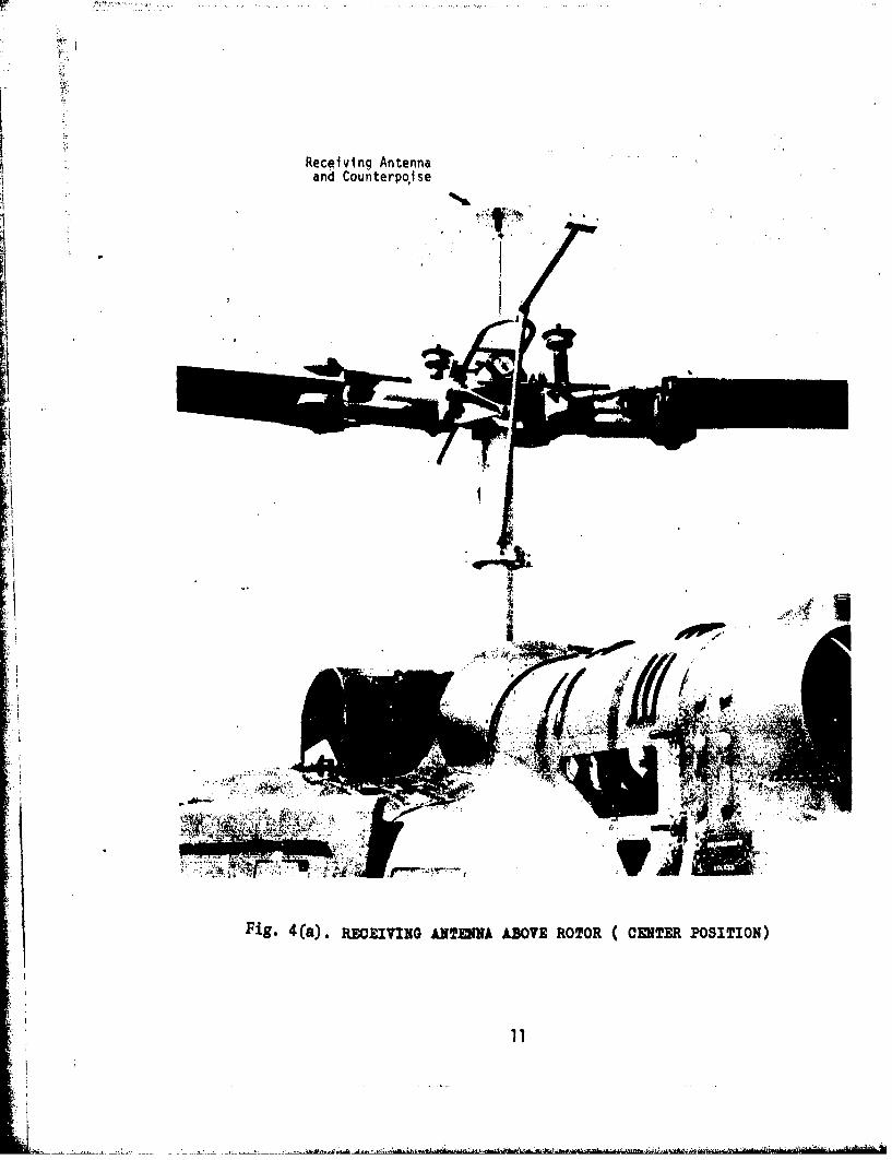
A simple dipole antenna tuned for operation at ý.1.575 GHz was usedto receive either horizontally or vertically polarized test signals. Tominimize excitation of the feedline and supporting structure, a sleeve chokewas incorporated with the antenna support post. The antenna was mountod aquarter wavelength above a removable counterpoise. The effectiveness ofcounterpoise shielding was indicated by the differences in the received ampli-tude and phase as a fur.:tion of a 1 X and a 2 x diameter counterpoise. Theantenna is protectcd 0.y a thin plexiglass bubble secured to the counterpoise.
The antenna, counterpoise, and protective bubble were mounted on a longsupporting tube. This assembly was cente:-ed at the top of the hollow rotorshaft by a large teflon bearing (Fig. 4(a)] and secured at the stationarybase of the synchro-positioner [Fig. 4(b)]. This allowed the rotor to turnfreely while the antenna remained fixed. For measurement purposes, the tube* length was sufficient to allow a 0- 1 xchange in the antenna height above thetop surface of the rotor blade. Due to the physical constraints imposed by
* the blade control mechanisms, what is referred to in the data as the zeroposition of the antenna was actually a height of 1 x above the blade.
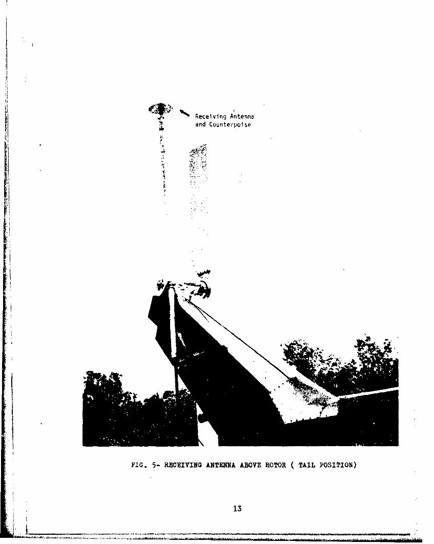
The antenna assembly mounted on the helicopter tail is shown in Fig. 5.The antenna-suppctting anj height-adjusting tube was mounted concentricallyinsiae ý 5-fuot ling retal tube which was fa-tened to the tail fin ot thenelicopter. This arrange;7ent provided a 0-1 height adjustment. As intre previous ca:e, :erc nellht was 1 ? above t., :,p sirface of the main rutor.However, in this case tre reason for the offset wds tnat the large tail rotor"had to be cleared by the antenna (see Fig. 6). This tail rotor could berotated manudlly, and several tests to determine its influence were performed.
A. Test Series
The amplitude and phase variations of a microwave carrier v.'chwould occur in actual fliaht can be determined from CW measurevent•. This
K - ~'.----.*~r - -
can be seen by considering that the propagation time nf the field scatteredfrom any portion of the rotor, to the antenna is much smaller than the timerequired for an appreciable change in rotor position* to occur. Thus thesignal fluctuations caused by the scattering have already stabilized beforethe rotor has moved far enoLqh to cause significart changes in the receivedsignal. Of course, time delay distortions resulting from multipath canstill cause errors in the coded signal.
Tables I and II give a list of the parameters considered in the CW ex-periments for the center and tail locations, respectively. A cross-sectionof the measured curves is given by the figures of Appendices II and III. Thecoordinate system for the CW experiments is shown in Fig. 7. Polar anglesfrom 450 to 105' with respect to the vertical axis were investigated (theformer is the minimum angle considered since evaluation of the data indicatedno unusual results to be expected at steeper angles). The 105° angle wasselected to represent the conditions obtaining during banking maneuvers.
B. Amplitude Variations
Amplitude reductions as a function of direction of incidence areshown in the 3-dimensional presentations of Fig. R (for center position) andFig. 9 (for tail position). These diagrams show the worst case receptionfor each direction of incidence. The numerical values represent the maximumreductions below undistorted levelt observed during a series of tests to de-termine the effect of variations in polarization, counterpoise size, andheight. In general, most of the worst case data for the center positionresulted from tests with the small counterpoise. The large-counterpoise dataexhibits somewhat smaller changes in signal level (I to 3 dB less) fore < 600. For larger angles o > 85% the data is comparable to that for the1 •-diameter counterpoise. Peak-to-peak fluctuations in amplitude wereeven greater for some cases than the attenuation levels shown in Figs. 8 and9. However, increased receiver sensitivity is more difficult to achievethan dynamic range in current GPS receivers, hence the attenuation data isa better indicator of receiver requirements.
C. Phase Variations
The 3-dimensional plots given in Fig. 10 (for center position) andFig. 11 (for tail position) show the maximum phase shifts sustained by thereceived signals as a function of the direction of incidence. The phasevariations, of course, are continuous functions of rotor positior; in somecases these variations may be symmetrical about 00 while in others they mayoccur in one direction only. It is difficult to estimate the effect ofthese phase variations on receiver performance without additional knowledgeof the receiver design. However, in those cases where a 1800 shift occurs,an incorrect bit is introduced into the code and, even for somewhat smaller
1 X at the rotor tips.
'The level received when the rotor was moved to the position ofleast interference.
3
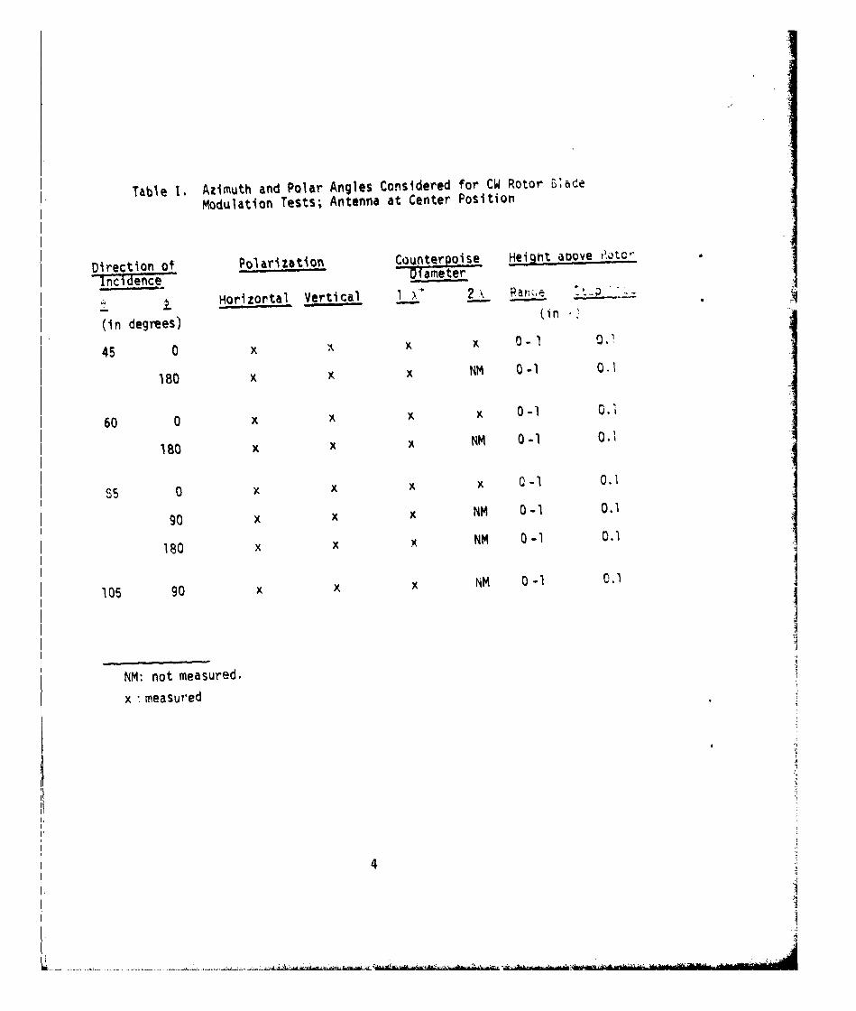
Table I. Azimuth and Polar Angles Considered for CW Rotor £2ade
Modulation Tests; Antenna at Center Position
Direction of Polarization Counterpoise Height auove r•otc'
-Incidence D-lamer
Horizortal Vertical I x 2 \ a r
(in degrees) (in
45 0 x x x 0- 1
180 x x x NM 0-1 0.1
60 0 x K K x 0-1 0.1
180 x x x NM 0-1 0.2
S5 0 x x x x 0-I 0.1
90 x x x NM 0-1 0.1
180 x x x NM 0-1 0.1
105 90 x x x NM 0 -1 0.1
NM: not measured.
x 'measured
4 I
- - - &.
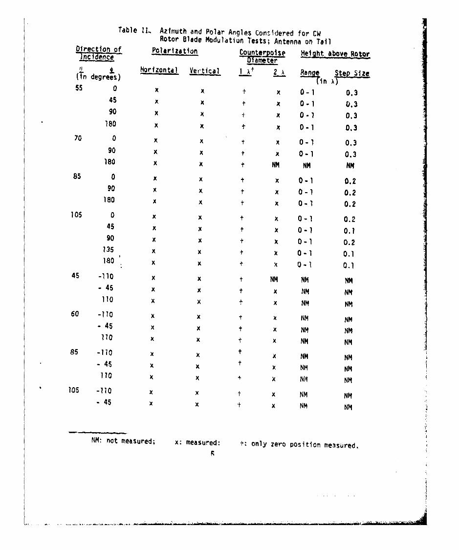
Table I&.. Azimuth and Polar Angles Considered for CWRotor Blade Modulatiun Tests; Antenna on TailDrection of PO zajto Counterpols
DIreto ofPlarizaton Coun er, Height above Rotor
Inciim eDiamter11 LHorizontal Vertical I A, 2~ x aa St S(Tn degrees) ("n A,
55 0 x x t x 0-1 0.345 x x 0-1 0.390 x x t x 0-1 0.3
180 x x t x 0-1 0.370 0 x x t x 0-1 0.3
90 x x t x 0-1 0.3180 x x t NM NM NM
85 0 x x t x 0-1 0.290 x x t x 0-1 0.2
180 x x t x 0-1 0.2105 0 x x t x 0-1 0.2
45 x x t x 0-1 0.190 x x t x 0-1 0.2
135 x x t x 0-1 0.1180 x x t x 0-1 0.1
45 -110 x x t NM NM NM- 45 x x t NN NM
110 x x x NM NM60 -110 x x t x NM NM
- 45 x x t x NM NM110 x x t x NM NM
85 -1 i 0 x x NM NM t-4S x x x NM NM
110 x x t x NM NM105 -110 x x t x NM NM
- 45 x x x NM NM
NM: not measured; x: measured: t: only zero position measured.
phase deviations, long integration intervals in the receiver could resultin the detection of a large number of bits with incorrect coding information.For 0 ', 850, nhase variations increase drastically and, in some directiorts,phase 10eversa's • IBO shifts occur.
4. DATA ANALYSIS
It is apparent from Figs. 8 to 11 that the tail position is a betterlocation for the antenna than the center position. Consider in particularthe data for = 105c, which simulates a turning and banking maneuver. Forthis ;ŽuZU, angle, regardless of antenna placement (center or tail positionon helicopter), signil degradation is severe. Although this degradationobtains for all zc'; angles at the center location, severe fluctuationsat the tail location occur only over an azimuth range of -. 60' around . = 0'.In the former case, the rotor always intercepts the signal at the polar angle
'C••' regardless of the azimuth; for this reason loss of lock in thereceiver is a distinct possibility. At the tail location, however, the bladedoes not intercept the signal directly except over the azimuth range justmentioned. Furthermore, most helicopters normally fly in a pitched-forwardattitude, so that the directions of incidence in the tests where large signalperturbations occurred, such as ! =15' and i -', may not occur in practice.
Considerably different responses were observed between horizontally andvertically polarized signals. In general, the horizontally polarized signalsexhibited greater amplitude and phase fluctuations over all angles of inci-dence and, in particular, near grazing incidence. The reason for this be-havior can be seen from the following argument. The tangential component ofthe e~ectric fiela in the incident wave must be zero at the metal surface ofthe rotor blade. It is apparent that the greatest disturbance in the re-ceived field will occur when the blade is in the plane of incidence, ratherthan perpendicular to it. In the latter case, the effective scatter area ofthe blade, from which significant contributions to the received field strengtrnare made, is considerably reduced, as shown qualitatively in Fig. 12(a).Figure 12(b) shows the increased blade area from which scattering contributesto the receiving antenna when the blade is parallel to the plane of incidence.This is indeed th2 case as shown by the data presented in Appendices II andIII. I
The following description pertains to the parallel orientation of theblade. In this case, for horizontal polarization of the incident signal,the electric field of the incident wave is entirely tangertial to the blade,and trie reflection coefficient at the metal surface is -l, i.e., total re-'Ilection with a phase reversal. Thus, near grazinr incidence, 90", vinerethe path lengths of the direct and reflected field are appruxii'ately ehua,the tiw, field components tend to cancel at the receiving antenna, producingzero signal. On the other hand, the tangential component of a verticallypolarized signal is a function of incidence angle and approaches zero near'grazing incidence. The reflection coefficient at the blade surface is +1,i.e., tota! reflection but no phase reversal, and the equal path lengthsoccurring at shallow incidence angles result in reinforcement of the re-ceived signal. At - = 0', the rotor causes a strong scatter field for bothpolarizations since there is essentially no difference in the tangentialcomponent of the incident wave. Nowever, the counterpoise effectivelyshields the antenna f:'om this disturbance. For angles of incidence betweenthe t'io limiting cases ( 0' O0 and = 90'),the tanQential component of the
6
L ... :

horizontally nolari:ed signal will always be greater than that of the ver-tically polarized signal, and the fluctuations due to scattering will be moresevere. This behdvior becon;es more apparent at increasing angles of incide.mce.
Circular polarization should minimize some of the fluctuations observedsince they are caused by reflections from metal surfaces and will have apolarization sense opposite to that of the incident radiation. Thehelicopter antennas, of course, should he designed for optimumreception of the latter radiation.
Similar phase and amplitude distortions were measured at the two an-tenna positions for polar angles 470*. Examination of the curves in Appen-dices II and III also shows that the worst-case conditions depicted in Figs.8, 9, 10, and 11 artually occur rover, at most, a 40" sector of rotor rotationfor the tail position and a 60' sector for the center position. Two suchdisturbances occur for each complete rotation of a single-bladed helicopter.Since the rotor on the UH-lB turns at v330 rpm, a disturbance of the signaloccurs at an 11 Hz rate with a duration of -20 to 30 msec per disturbance,depending on the location of the antenna. This fact coupled with the signaldegradation levels given in Figs. 8 to 11 is indicative of the receiversensitivity required at the present time.
5. CONCLUSIONS
The results of this study show that it is more advantageous from an elec-trical as well as from a mechanical standpoint to locate the antenna on thetail rather than at the center of the helicopter. However, an antenna assem-biy which is aerodynamically acceptable must be designed. Two electricalproblems still exist for the tail location. Because of the long RF cablefrom the antenna on the tail to the receiver in the cabin, a low-noise pre-amplifier may be necessary to maintain an acceptable signal-to-noise ratio.The second problem involves the poor response of planar antennas to signals !arriving at or near grazing incidence. In this case, antennas of nonplanardesign or conical spirals are strongly recommended. However, such three-dimensional designs are subject to somewhat greater influence from the rotorand helicopter. In this regard, the counterpoise having a diameter of onewavelength was found to be sufficient to minimize rotor modulation of thetype discussed previously. The larger diameter counterpoise is more effectiveat the center location. Follow-up studies to determine the proper singleantenna configuration, and investigation of multiple antenna configurationsusing switching and/or phasing techniques should be undertaken as a nextstep.
ACKNOWLEDGMENTS
The authors wish to thank Mr. J. R. Wills of the Antenna Research Teamof the Communications/Automatic Data Processing Laboratory, ECOM, for hisable assistance in performing the numerous and detailed measurements of thisstudy. Thanks are also given Messrs. I. Levine and J. Gray of the AvionicsLaboratory, ECOM, for their technical and administrative support, and to theU. S. Army Satellite Communications Agency, the sponsor of the programleading to the results given in this report and those given in reportsECOM-4254 and-4255, September 1974.
7
Pn t r"
Fig. 1. Wayside test site. X
8f~k
L Ii
4al
to
P01
0.
cmA
k tlit
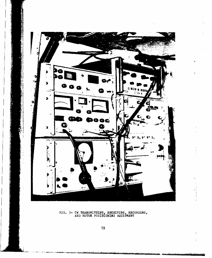
FIG. 3-CW TRANSMITTING, RECEIVING, RECORDING,AND ROTOR POSITIONING EQUIPMENT
10
Receiving Antennaand Counterpo~ise
JA 4
Fig. 4(a). RECEIVING ANTENNA ABOVE ROTOR (CENTER POSITION)

DIPOLE ANTENNA
S- PLEXIGLASS
COUNTERPOISE BUBBLE
TEFLON BEARING 4,-OSUPPORT TUBE
ROTOR
• I N HOLLOW ROTOR SHAFT
100,
-~ i i
Ft4 -
II ( I '
I ISYNCHRO-SPOSITIONER
HEIGHT ADJUSTING COLLAR STATIONARYSHEIHT DJUSINGPLATFORM
FIG. 4(b). ANTENNA AND SUPPORT TUBE MOUNTED IN THE HELICOPTER
12
Receiving Antennap1 S nd Counterpoise
FIG. 5- RECEIVING ANTENNA ABOVE ROTOR (TAIL POSITION)
13

tI
114 i-i
SSt l O W I N G T rII I E n I I C O N S T R A I N T i M P O S E D B Y R T A I L R ONTF •
, 14
DIRECTION 0F INCIDENCE* I
I;I
BLADE
I "1 HELICOPTERLONG AXIS
FIG. 7-COORDINATE SYSTEM FOR CW ROTOR BLADE MODULATION EXPERIMENTS
15

!*
I
A!
I
I
INM: NOT MEASURED
: 'I
jI FIG. 8- AMPLITUDE REDUCTION DUE TO ROTOR BLADE-
WORST CASE RECEPTION (EXPERIMENTAL) FOR
ANTENNA ABOVE ROTOR (CENTER PosITION)
16
-of
FIG. 9. kMPLITUDE, REDUCTION DUE TO ROTOR BLADE-WORST CASE RECEPTION (EXPERIMENTAL) FORANTENNA ABOVE R0om (TAIL POSITION).
17

z*
11Apo
am0
I
I' NM: NOT MEASUREDI
Ipt
FIG. 10. PHASE DISTORTION DUE TO ROTOR BLADE-WORST CASE RECEPTION (EXPERIMENTAL) FORANTENNA ABOVE ROTOR (CENTER POSITION)
18

4ei
IA
FIG. 11, PHASE DISTORTION DUE TO ROTOR BLADF-WORST CASE RECEPTION (EXPERIMENTAL) FORANTENNA ABOVE ROTOR (TAIL POSITION)
*19
INCIDENT WAVE
0 EFECTIVE"- SCATTER AREA
a) ROTOR PERPENDICULAH TOPLANE OF INCIDENCE
II
II
INIDN IIý
: •mANTENN A
EFFECTIVESCATTER AREA
i) ROTOR PARALLEL TOPLANE OF INCIDENCE
FIG, 12- EFFECrIVE SCATTER AREA OF THE ROTOR PLADE
20
APPENU;X I
WORST-CASt ANAI.Y!-; ,F )r TOR--PLADE JFFFCTS UN A.NTENNASMOUNTHf) AROV! THE ROTOR AT THIL TURNINC AXIS
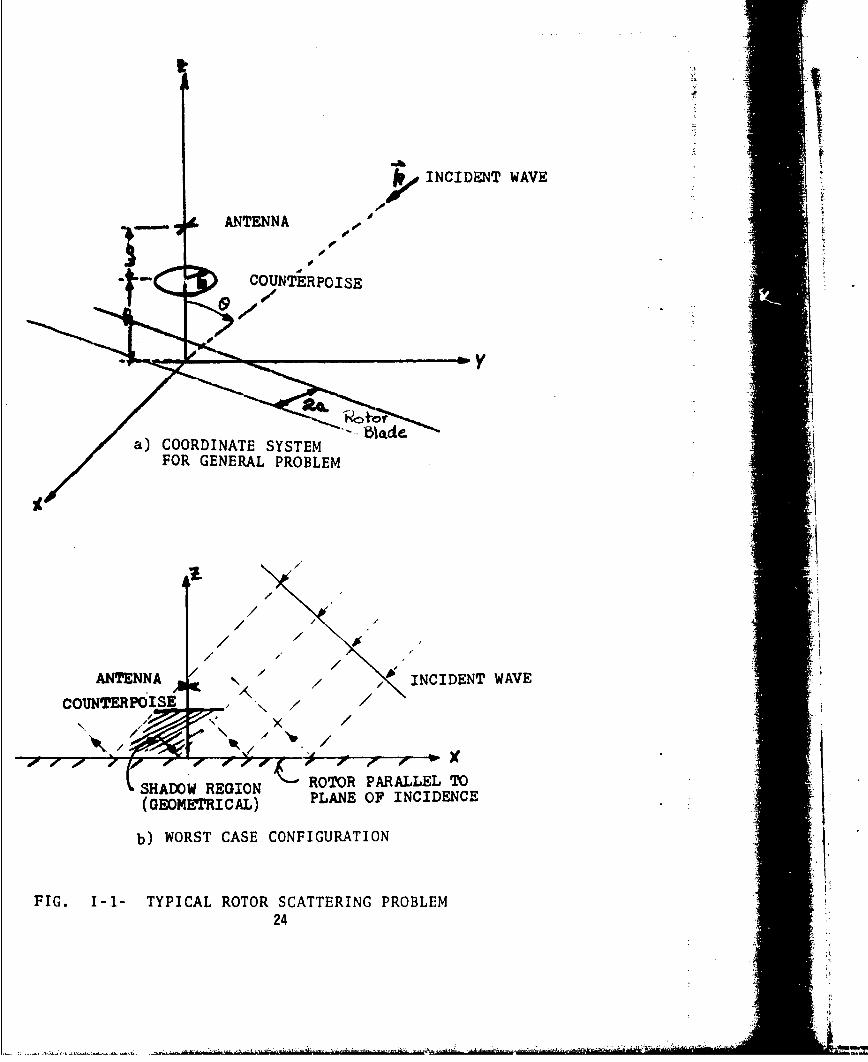
.c.-,id -'r the ba(ksc(jtLer of th, rutur blade and its effect on a signalreceio,', at thf. antennti in the configurtioti illustrated by Fig. 1-1(a).Scatt-rinQ will be q,-eatest when the rotor blade is parallel to the plane ofincidence, is depicted in Fig. I-lhb). the worst-cdse configuration. An inci-
dent plane wave field, in the two-di,,ensional case of Fig. 1-1(b) given by
, 0 ex j,-.,)k(jx + .z) (1)
where .i - -sin,,, ..... illuminates the antenna and rotor blade. To someextent, a counterpuise shields the antenna from the backscattered field of therotor. This field accordling to rl] is:
a
,o- 2rv I-u ds, (2)E2(xý 7) 2. 173/l~•..oZep(ju )•ar2
-ar
where r - V(y'-t) 2 + z2 a is the rotor blaae half-width, and primed quan-tities denote obsevvation points. What is the resultant field at the antenna?Tc simplify this problem, several assumptions will be made. We assume that:(1) the strongest distortion oF the received field occurs only when the bladeis in the plane of incidence (see the Sections "Data Analysis" and "Conclu-sions"); (2) the rotor blade surface is planar; (3) the blade extends to t-in one dimension; (4) the effect of counterpoise shielding on the rotor isnegligible [see Fig. 1-1(b)]; and (5) the phase fronts of the scattered fieldat the location of the counterpoise are planar. Although these assumptionsresult in a somewhat greater reduction in the total field at the antennathan, ictuafly occurs, they provide an upper bound on the magnitude of thereduction and permit a simplification of Eq. (2):
E2 (x',z) = Eo.A(z).exp(-.jx' sine), (3)
where
[1] F. Schwering and c. M. De Santis, "Rotor effects on L-band signalsreceived by helicopter antennas. A theoretical study. Part I:Amplitude reduction and phase shift (shielding effect)," Researchand Development Technical Report ECOM-4254, U. S. Army ElectronicsCommand, Fort Monmouth, N. J., September 1974 (AD 787363).
21

a ;
A(z) =+ .z.ose *f d12 coexpL-jW z4_Zs2 cose + 3-n)l dsA(Z) + exP- COS + TY (z +s 2)3/444
All I ,ear dimensions have been normalized by multiplication with k 2w/X.The field expressed by Eq. (3) illuminates the counterpoise from below, WhenEq. (3) and the appropriate Green's function for a plane surface are used inGreen's Theorem, the field scattered by the counterpoise is
1 b 21r _ r P,(5Ee(x'z) E E(x',h) 7re
where R - r 2 + . The geometry for this aspect of the problem is
shown in Fig. l-2(a). Integration with respect to 0 and partial integration tover r may be performed to give:
b-,
E3(z = JR b b jRE3(z) +EoA(h)';-ýJo(r sine)"T 0O• i•:!•
sn• + sine- Jl(r sine) RFdr (6)
forX' = . Jo and J1 are the first- and second-order Bessel functions of thefirst kind. A(h) is obtained from Eq. (4) for Z = h. Equations (3) and (6)are added to obtain the total field received at the antenna location whenthe field produced by the rotor is scattered by the counterpoise, i.e,
E2 3 (z) = E2 (z) + E3 (z). (7)
A further contribution to the total field at the antenna must be con-sidped: the backscatter of the finite diameter counterpoise illuminated bythe primary field. The coordinate system applicable to this problem is shownin Fig. 1-2(b). Using Green's Theorem, the primary field of Eq. (1) and an 4t.approximate set of boundary conditions at Z = h,
-E=(r,h) Ecounterpoise(rh) for r < b INA
Ecounterpoise(r.h) - 0 for r > b,
22
4,Af

the backscatter field is:2Tr b te.jR•
E + E l(r,h) j r dr do (8)Ecounterpoise() + R 4
0 0
where R . Integration with respect to o and partial integrationover r yields
-RbE r (c) + Eo.-.exp(jh cose). {d(r sine) e bCounterpoise 0R 0
bp, -JR
+ sine.j Jl(r sine) e - ,dr (
0
The total field at the antenna due to this contribution is given by:
Ecl (z) = E1 (z) + Ecounterpoise(z) . (10)
The total field at the antenna from all sources can then be determined byadding Eqs. (7) and (10):
ET = E23 + Ecl. (11)
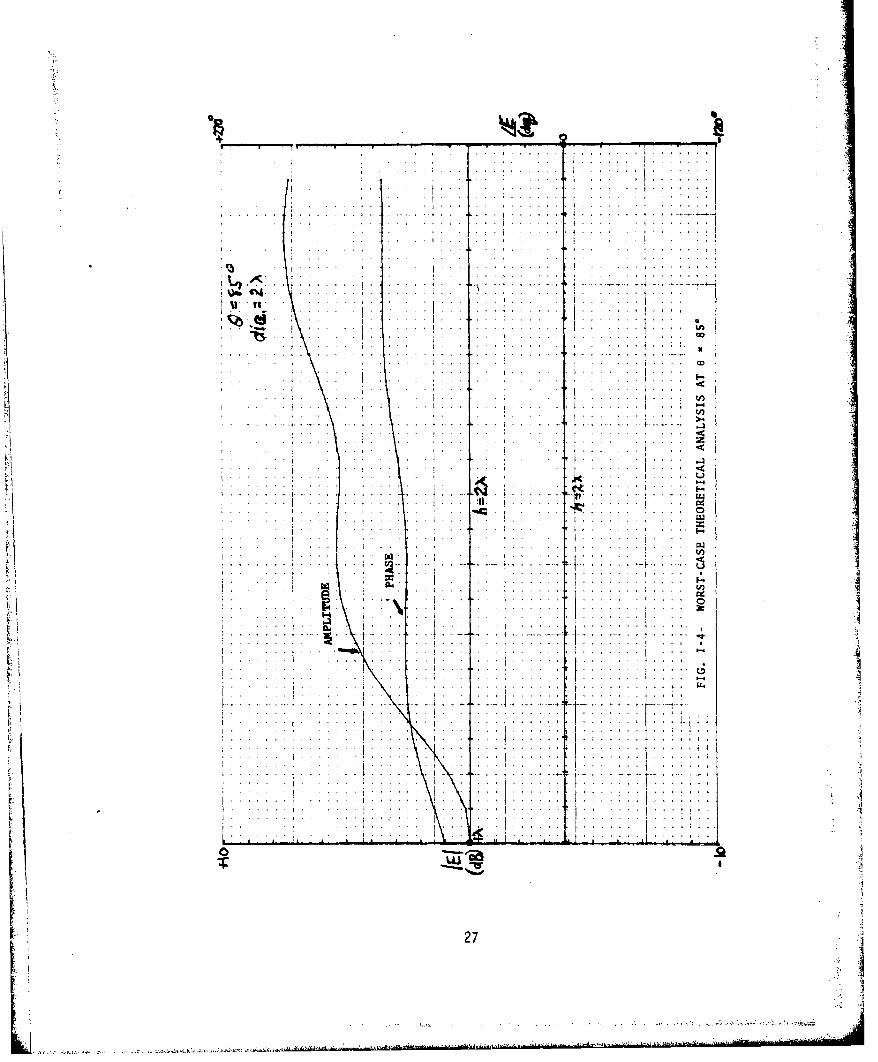
Equation (11) has been programmed for numerical evaluation,and someresults for e = 450 and 850 are shown in Figs. 1-3 tc I-4.* Figure 1-3 alsoillustrates the effect of counterpoise diameter. The amplitude curves arereferenced to the theoretical value of the received field at the 0 position(i.e., l x above the rotor). Comparison of these curves with the appropriatedata of Appendix II shows fairly good agreement with regard to the amplitudeexcursions and the slope of the phase variations. Further detail is lost inthe experimental data. The abrupt change in phase shown in Fig. 1-3 (a 3600phase jump) was caused by the automatic plotting routine and was not a trueeffect. A more exact theory of rotor modulation for the antenna at bothpositions above the rotor blade has been attempted, but no results are avail-able at the present time.
At or near grazing incidence, this theoretical description of counterpoiseeffects cannot be expected to be accurate. In fact, the curves in Fig. 1-4tend to diverge with increasing height. However, for 0 < h < 1 x, thetheory is in fair agreement with the measured results.
23
• INCIDENT WAVE
ANTENNA A,
COUNTERPOISE
001,
a) COORDINATE SYSTEMFOR GENERAL PROBLEM
b/
/ ,2
/ / /x#
//ANTENNA / / "\* INCIDENT WAVE
N. AI
COUNTERPOISE \ / /
SHADOW REGION ROTOR PARALLEL TO
(GEOMETRICAL) PLANE OF INCIDENCE
b) WORST CASE CONFIGURATION
FIG. I-I- TYPICAL ROTOR SCATTERING PROBLEM24

ANTENNA
COUNTERPOISE.
// .INCIDENT WAVE
PLANE_ OFROTOR_
a) GEOMETRY FOR DETERMINATION OF COUNTERPOISE EFFECTON FIELD SCATTERED FROM ROTOR
INCIDENT WAVZ
ANTENNA
COUNTERPOISE
b) GEOMETRY FOR DETERMINATION OF BACKSCATTERFROM COUNTERPOISE !N PRIMARY FIELD
FIG. 1-2- SCATTER EFFECTS CAUSED BY COUNTERPOISE
25
-4

.. .................... ...
.. . .. . .. .
.... ....+X
....... ..6
. .. .. . . .
.~ . ... . . . . . . . .
. .. I jý
. . .. . .. . . . . . ...
. .. . . ......... ...... .
. . ... . . . . . .
27,
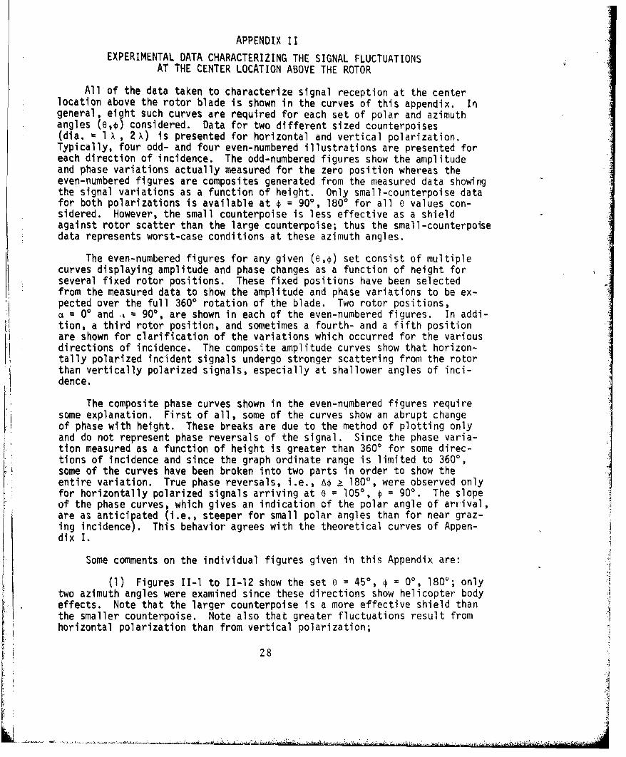
APPENDIX IIEXPERIMENTAL DATA CHARACTERIZING THE SIGNAL FLUCTUATIONS
AT THE CENTER LOCATION ABOVE THE ROTOR
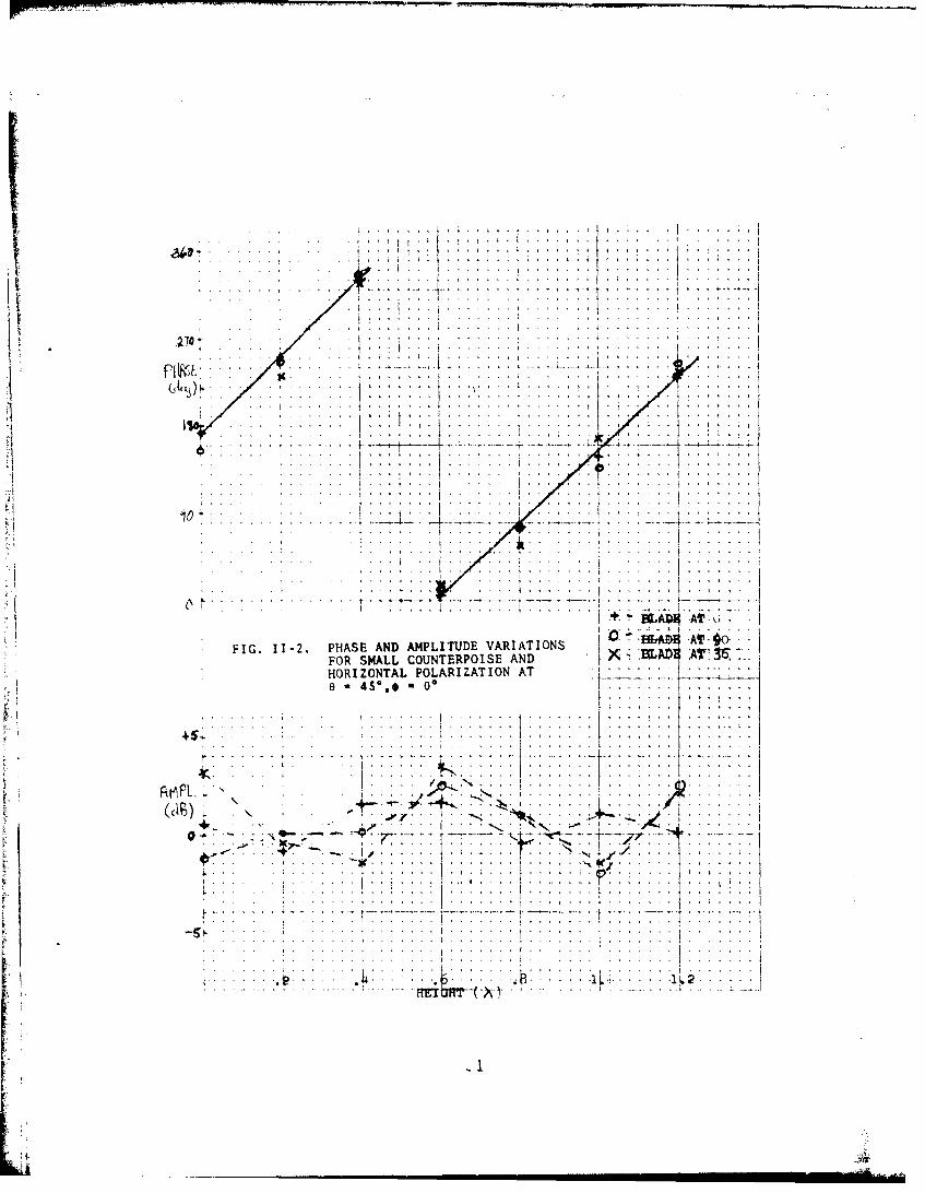
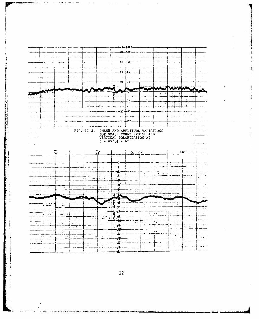
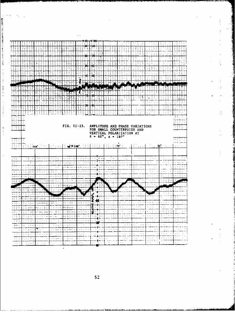
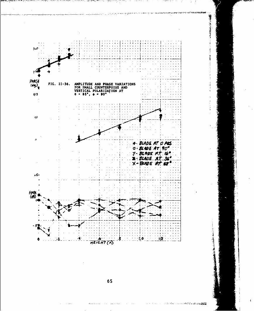
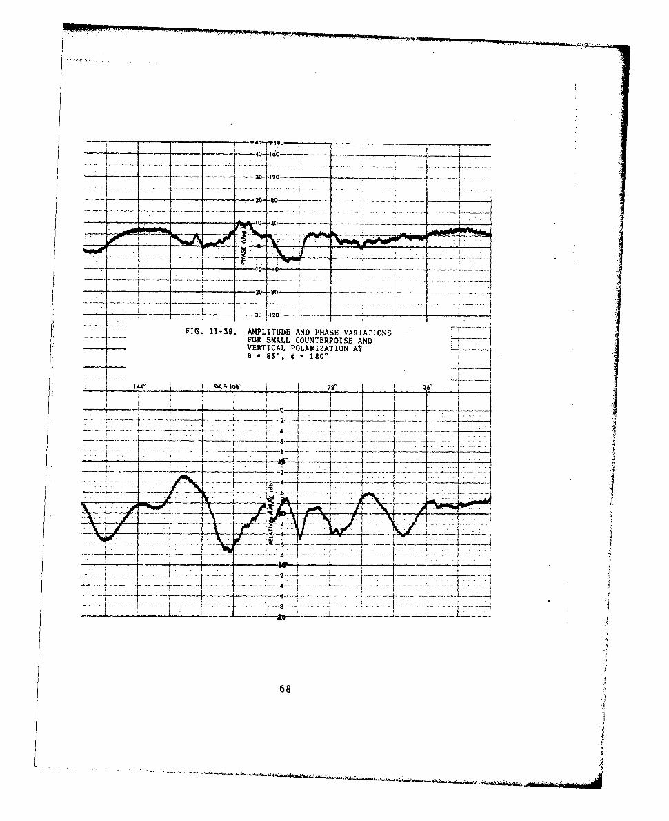
All of the data taken to characterize signal reception at the centerlocation above the rotor blade is shown in the curves of this appendix. Ingeneral, eight such curves are required for each set of polar and azimuthangles (o,ý considered. Data for two different sized counterpoises(dia. =1 X , 2x ) is presented for horizontal and vertical polarization.Typically, four odd- and four even-numbered illustrations are presented foreach direction of incidence. The odd-numbered figures show the amplitudeand phase variations actually measured for the zero position whereas theeven-numbered figures are composites generated from the measured data showingthe signal variations as a function of height. Only small-counterpoise datafor both polarizations is available at ý = 900, 1800 for all e values con-sidered. However, the small counterpoise is less effective as a shieldagainst rotor scatter than the large counterpoise; thus the small-counterpoisedata represents worst-case conditions at these azimuth angles.
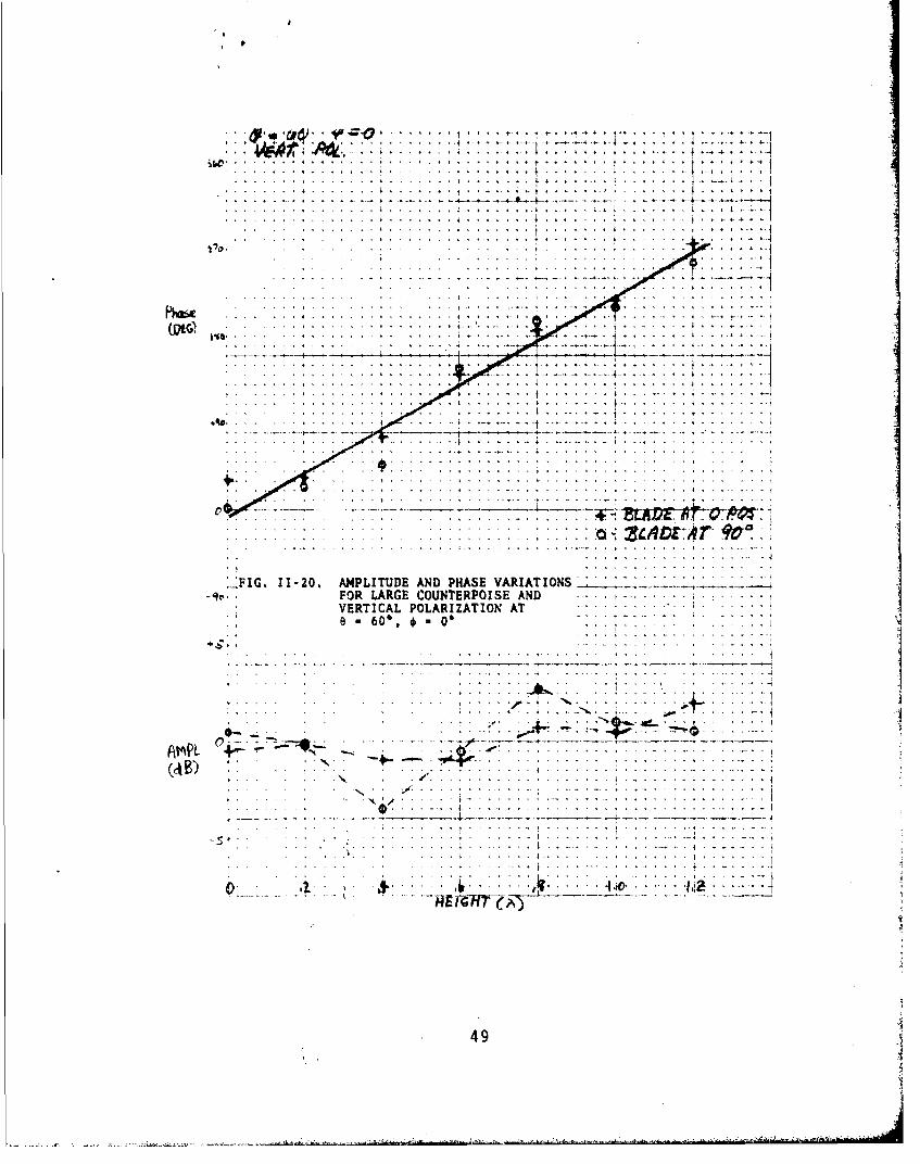
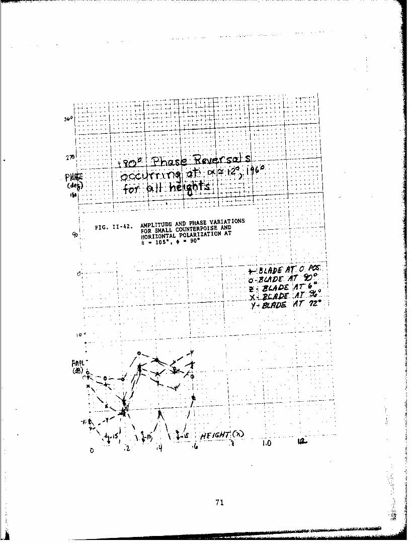
The even-numbered figures for any given (e,f) set consist of multiplecurves displaying amplitude and phase changes as a function of neight forseveral fixed rotor positions. These fixed positions have been selectedfrom the measured data to show the amplitude and phase variations to be ex-pected over the full 3600 rotation of the blade. Two rotor positions,
=0' and =900, are shown in each of the even-numbered figures. In addi-tion, a third rotor position, and sometimes a fourth- and a fifth positionare shown for clarification of the variations which occurred for the variousdirections of incidence. The composite amplitude curves show that horizon-tally polarized incident signals undergo stronger scattering from the rotorthan vertically polarized signals, especially at shallower angles of inci-dence.
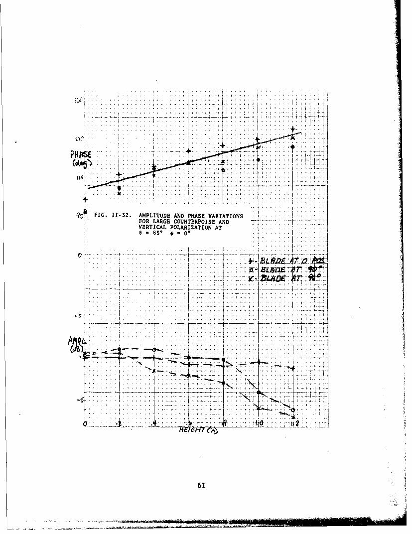
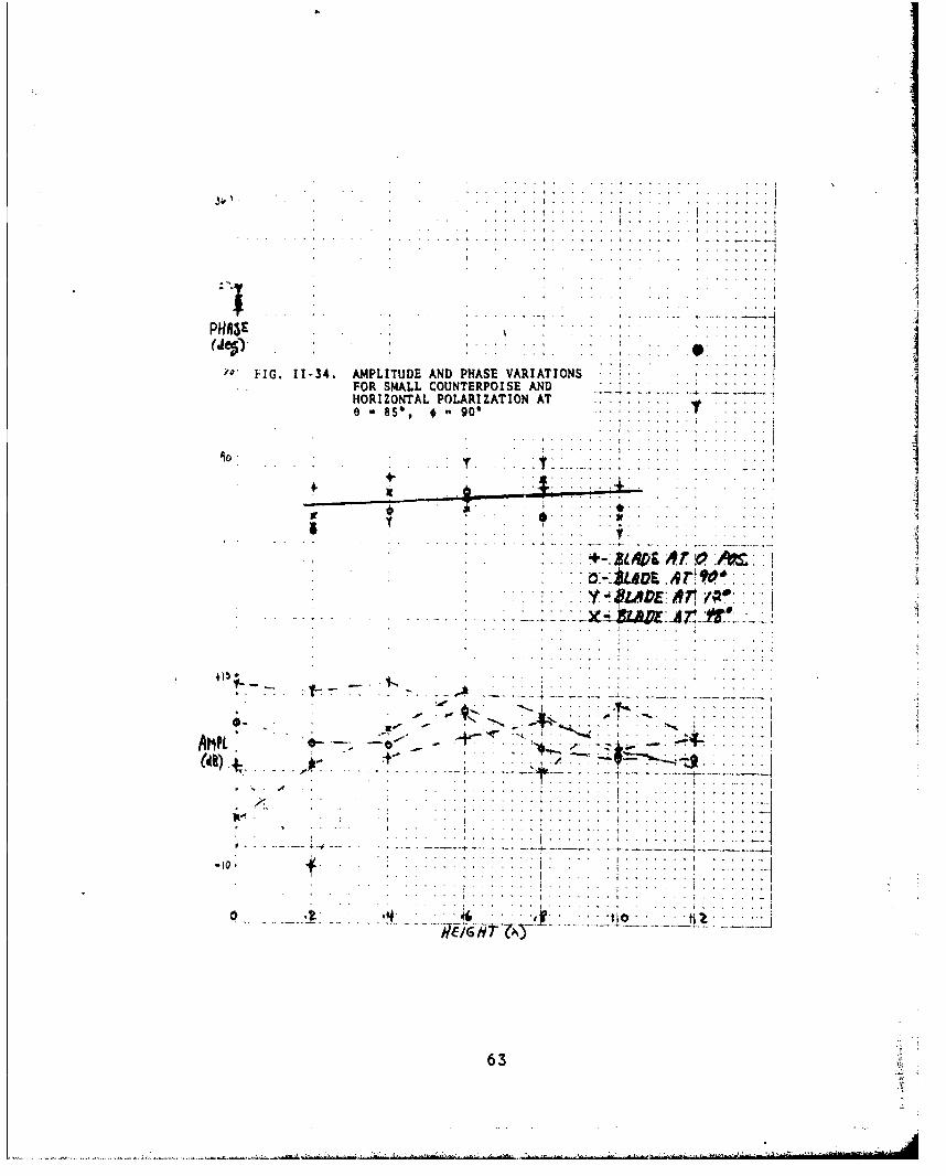
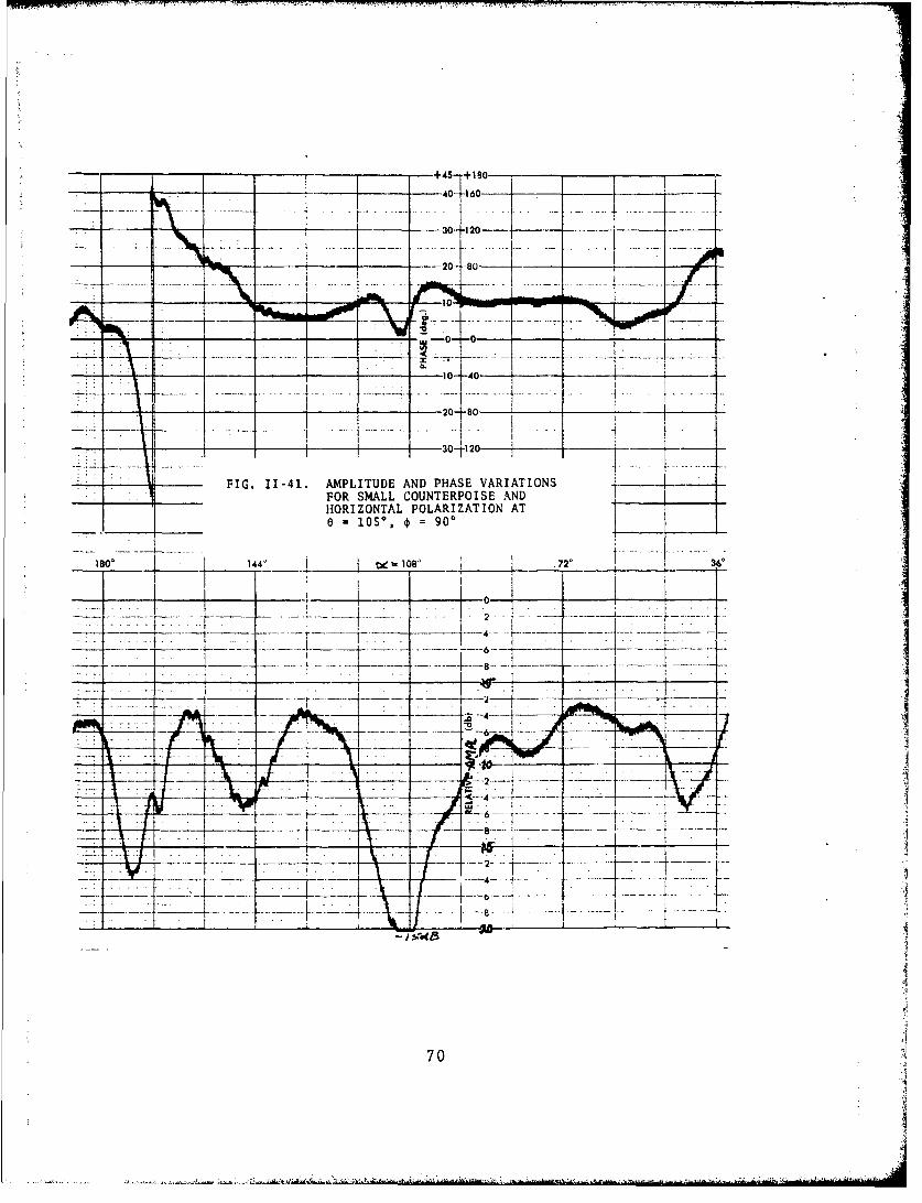
The composite phase curves shown in the even-numbered figures requiresome explanation. First of all, some of the curves show an abrupt changeof phase with height. These breaks are due to the method of plotting onlyand do not represent phase reversals of the signal. Since the phase varia-tion measured as a function of height is greater than 3600 for some direc-tions of incidence and since the graph ordinate range is limited to 3600,some of the curves have been broken into two parts in order to show theentire variation. True phase reversals, i.e., Aý a l80*, were observed onlyfor horizontally polarized signals arriving at e = 1050, =900. The slopeof the phase curves, which gives an indication of the polar angle of arrival,are as anticipated (i.e., steeper for small polar angles than for near graz-ing incidence). This behavior agrees with the theoretical curves of Appen-dix I .
* Some comments on the individual figures given in this Appendix are:
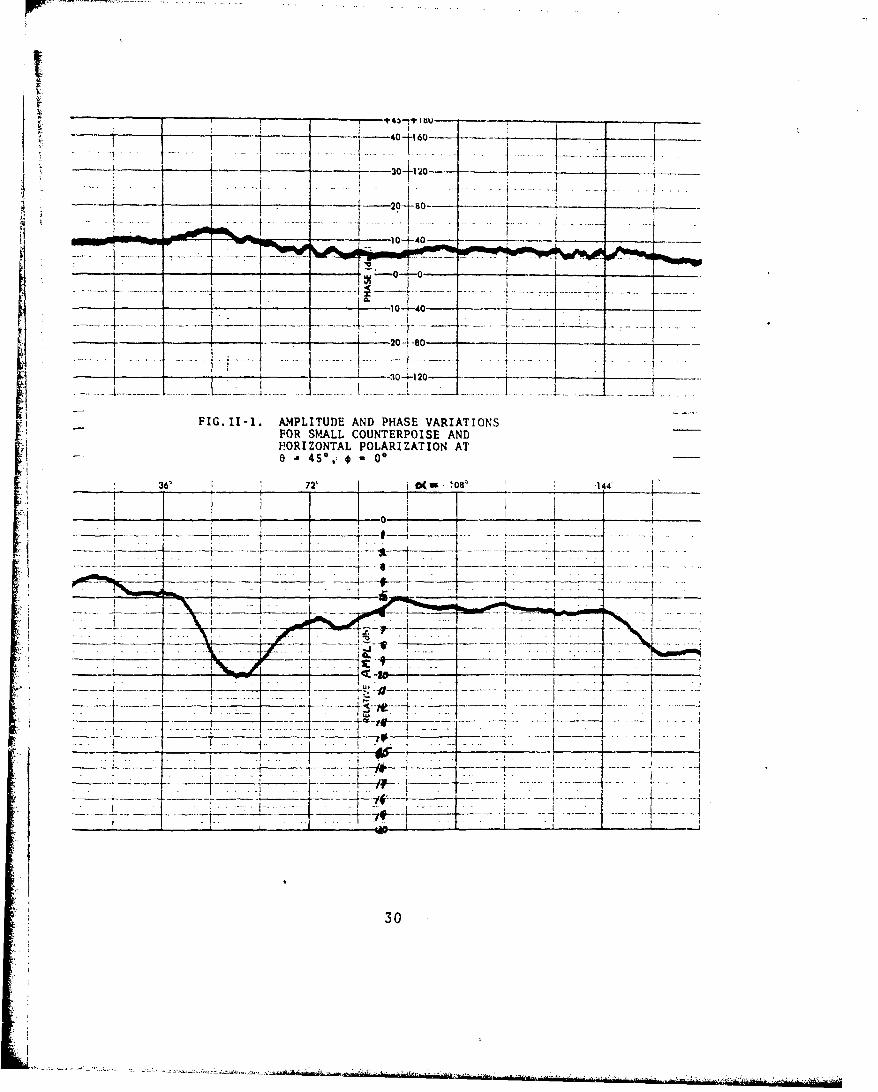
(1) Figures 11-1 to 11-12 show the set a 450, c~=0, 180'; onlytwo azimuth angles were examined since these directions show helicopter body
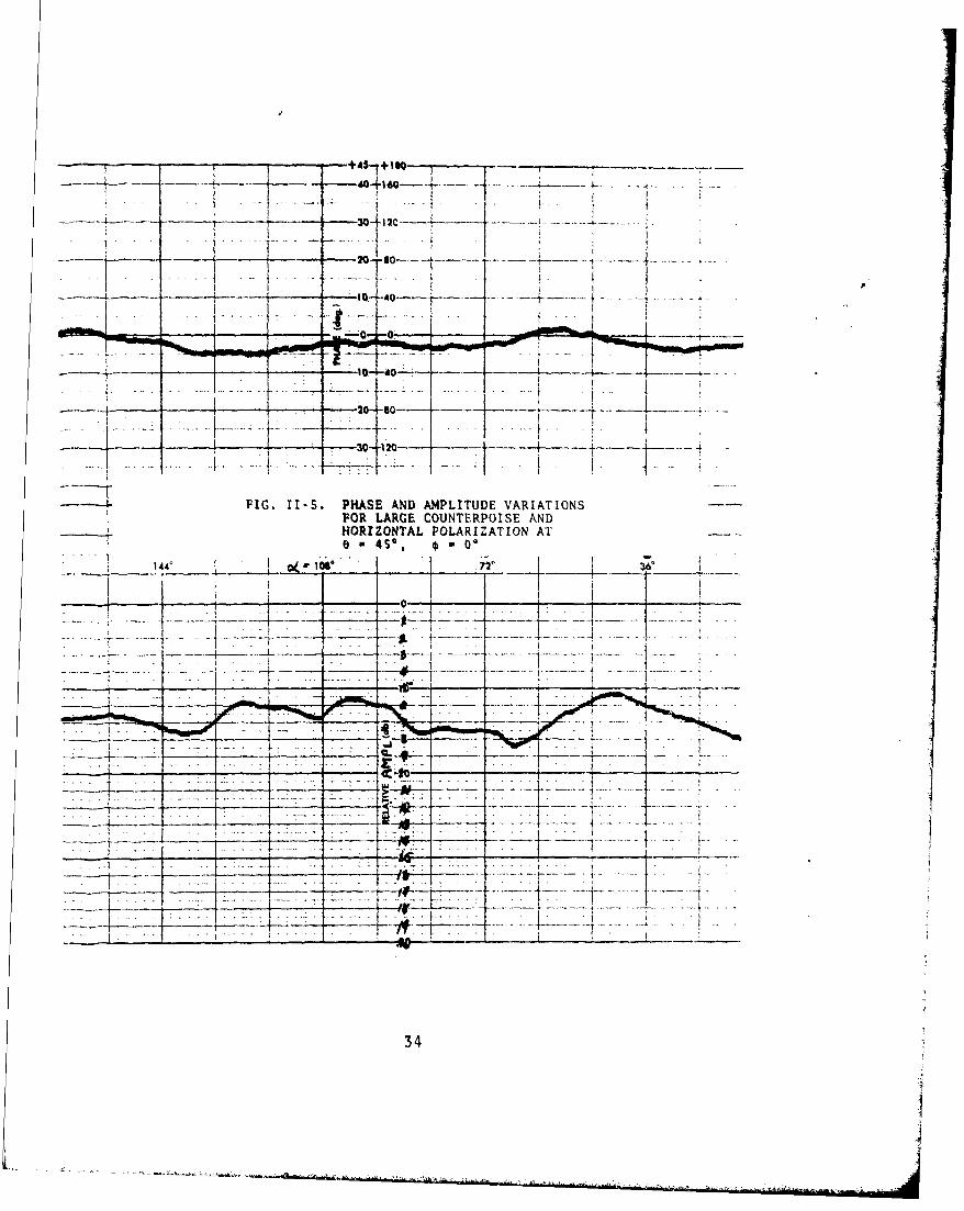
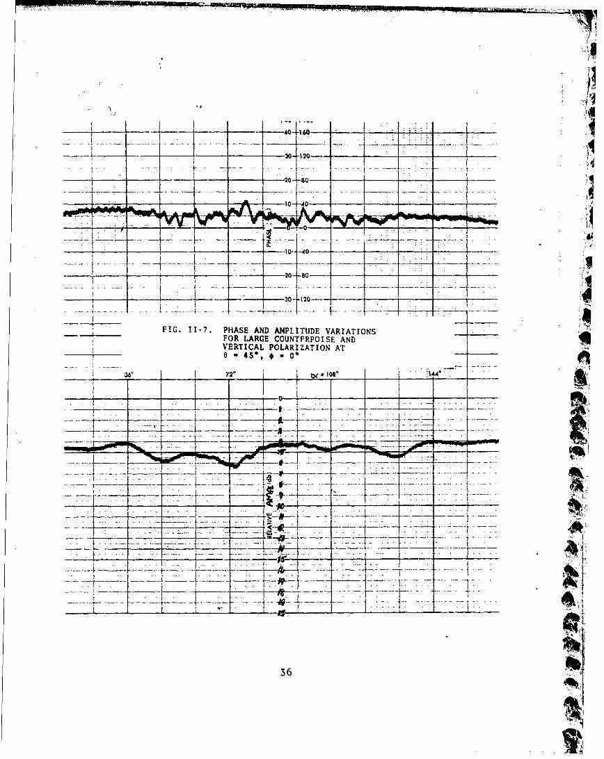
* effects. Note that the larger counterpoise is a more effective shield thanthe smaller counterpoise. Note also that greater fluctuations result fromhorizontal polarization than from vertical polarization;
28

(2) Figures 11-13 to 11-24 show the set e - 600 and o = 00, 180*.Differences in the shielding effectiveness of the large and small counter-poise become less significant for this direction of incidence. The generalcharacteristic of all these curves is that there is a I to 2 dB increase inthe amplitude variations as compared to those considered in (1) above;
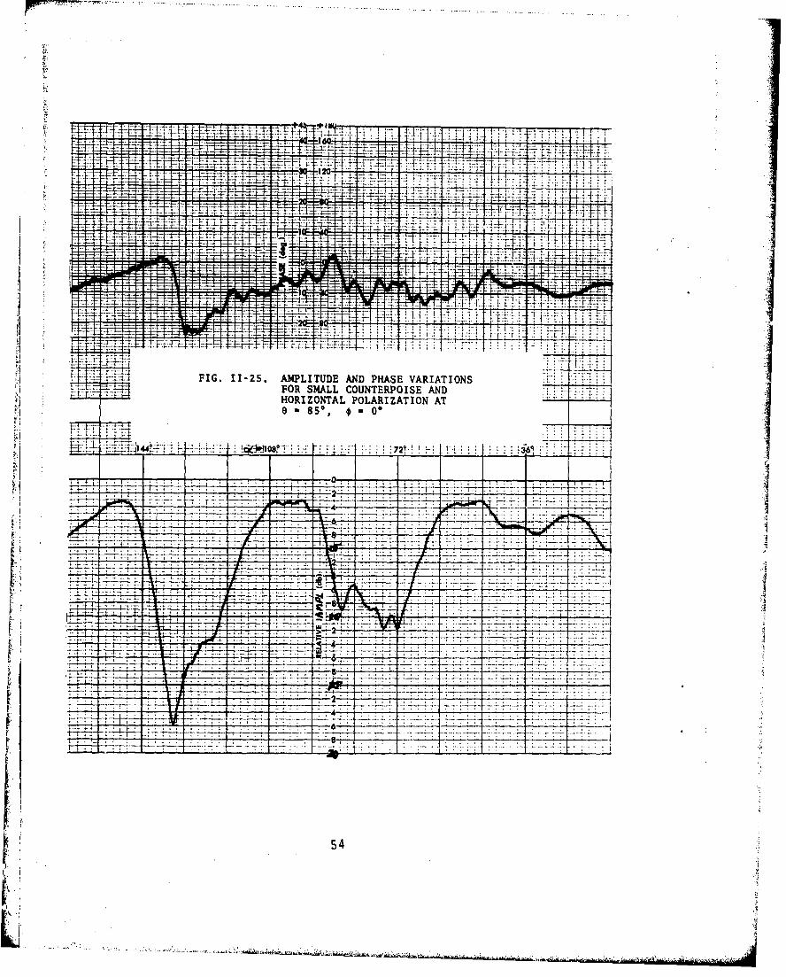
(3) Figures 11-25 to 11-40 show the set e = 850 and € = 00 9001800. Note here that the ordinate for some of the amplitude curves is 10 dBper major division rather than 5 dB and that the slope of the phase curvesis decreasing with increasing polar angle. Additional rotor positions havebeen included to indicate theincreased scatter effects of the rotor at largepolar angles; also not3, in contrast to the previous cases of (1) and (2)above, that a change in height did not reduce the scatter effects of therotor and that there was practically no differench in the shielding effec-tiveness of the large and the small counterpoise. The azimuth angle 0 = 900is shown for comparison with € 00 and 1800 in order to indicate multipatheff. .. s of the helicopter body;
(4) Figures 11-41 to 11-44 show the set e = 1050 and o- 900.This direction of incidence will occur during turning and banking maneuvers;it is apparent (although no measurements were made) that at e = 1050 and
1= 1800, the antenna will be completely shielded from the direct signalby the te4" boom, the tail fin, and the tail rotor resulting in completesignal d, .- out. True 180' phase reversals in the received signal occurredfor this cirection of incidence.
,I
"ii
29
.L-2.>...A ~ a.a2,. rT .. A~~aAl
4 -.--. -20- -S - - - -
- 4 -3 4- __20
FIG.II-1. AMPLITUDE AND PHASE VARIATIONSFOR SMALL COUNTERPOISE AND[ ~HORIZONTAL POLARIZATION AT
-6 72z* 081
_ _ _ _ T _ _ _ _ _ _
t tH _ _7
- .-,- - -~- - - ...- ,----- - -
-Irv
-. Ki'-- V .......-30 . . . .
I~ ...... ...... .. .......I.
... .. .. .. 1..
................................................,
4s,4
*1I .4..........I
.44
. . . .. . . , . .I . . .
FIG.~~~~ .12 PHS AN AMLTD VAITO . S I3 A. .9&...
Ot7VY -
Ii- - -- -- - 30 120---- - -- -~ ,--
1- 1 0 1 Leo
1777V ~ ~ 3 1it7 120 .
FIG. 11-3. PHASE AND AMPLITUDE VARIATIONSFOR SMALL COUNTERPOISE AND
VERTICAL POLARIZATION ATe-4S,ý 60
~~-1~~~ -.--- --0-
-- _ . 77 7. -
S-- .~4LXL' _71
'I . d-±I-f~-k 32

*. .. 4. .......
..... .....
..e .;: .:1..:
. . . . . . . . . . .
FI.11-4. PHASE AND AMPLITUDE VARIATIONSFOR SMALL COUNTERPOISE AND A*VERTICAL POLARIZATION AT a. LD.A
0 a 4,~ * .............
.4 . . . . . . .
.: .. :.. .. ................................ (....
33122
- -+~45. +1O-0~
- t10- 40
_____ I
FIG. I1-5. PHASE AND AMPLITUDE VARIATIONSFOR LARGE COUNTERPOISE ANDHORIZONTAL POLARIZATION ATe 00a
* 144' ~ j1S_ 1 .72' __
7,1
34__

+ " 4,
. .... . . . . . . . . .. .. . . .. .. .
II
*~ ~ ~~~ * * * ' . . . . . . . . . . . , -.
... .... . .. . . ...... ....... .......
•..~~~~ ~~ .-. '- .. ..•'. ,. ..,_, .. . .*' - " ." ."•. . .. . .. .. .. .. .
~. . . .. . . . . . . . .. . .' . . . . .. 1 . I. . . . . .. . ... . . . . . .. . .
. . . . ........ . ... .. .. .... ....
.... 4 . .... . . . .
4 i... .......
it . . . .
. . . .. ..*
. ..., .16 P.S AN A.LTU~ VA I TI N +. . .. . ... ..
%:44
HEIGHTi( X
35
--
4
30-112
I ~~~~~--~~20-8------------ ~ - 0j1 0- -
FIG. 11-7. PHASE AND AM4PLITUDE VARIATIONSFOR LARGE COUNTFRPOISE ANDVERTICAL POLARIZATION AT
- - - - I . ~~~~ ~ ~ 1 -- ------ u 0 _ _ _ _ ~' ----
41%36
IT'1

... . . . . .... r........- • ) F T • • I [ T - ' " T- T -~ f T T ) . ', • !
Ti r. T I
, -f-- f • -t t f I f - f , 1 I , ,
. . . . . +-. t
, - 4S*, 0* .. ;.; ''-w riit!•, , i ) i i ii t i . - i4
i~~~~~~~~~~~ ~~~~~ ... . .• .. ... ... .~ .. l. . . .. . .tf
S:, . , , i,4 4,i+ t,,
*4f4,4 t ,i
A F ... . . ./ . . . ,. , .; -+ l , .. .... ..' . , ! . .
. .......... ..... i,4., 4 , ..* . .../ •. . .. t' 4-,' '.4 • ' . .. .i, .. .t ! t '
FIG II8. PHASE AND AMPLITUDE VARIATIONS •, . . .. ; -• -,-
FI. I-. FOR LARGE COUNTERPOISE AND -,4 ,t4 4..... t ' )+ 4 .
VERTICAL0 4 ) IPOLARIZATION "AT ,--' 4-t _ . ..;.l i'F' • '' ,.A••I '4
".... .. .................... . ............... I..': .,
4 !
.4 , . . . ,,,. ',,44,4 ,* , ..*. . .
S . 1.. . .... .. .. I. .... . .. .. ....... ... )'''I..... .
.. ~ i
HET 0141' (XT-
37

- - - -~+45- +180- - - -
_______ - ~ 040 60-
--- 1-- - - 30--12 0-0
- ------- 0- 40--
_ _ _ _ _ 7~20 80O~
FIG. 11-9. PHASE AND AMPLITUDE VARIATIONSFOR SMALL COUNTERPOISE ANDHORIZONTAL POLARIZATION AT645*, *1800
I W-
_i_7 _ -...
-- A -7
- ~ ~ ~ ~ . ...~ E 71~ .. ....- -
38

t~4 I.4 -4 l'A4
4.90 -~ ~ ~ 4t * -I--tj
4-.-4
.5 . . . FI. . 110 PHS AN AMLTD VAITIN
HORIZONTAL POLARIZATION AT ~ ----
o-4S', * 1800 . .
1-%
.. ... . ....................
.. ..................... ......
39

-- -- 71 V 40I I160-
10 '40- --
-FIG. II-11. PHASE AND AMPLITUDE VARIATIONS- FOR SMALL COUNTERPOISE AND
VERTICAL POLARIZATION AT
-6 72' ~ * lO
--- --- -: 2 1 ____ - I- -
i-- -- - ---
-p-
.1 ___ 7
404

4, 4
7>:~~~ý -... :" vt K-.4I 4L t- -4 4 -+
.....t...4..44i-4--
.. .
414
t1
FG111. PAEADAPIUEVRAIN. O ML ONTROS N

- . ______ - +0- t18-o--
40- 160-
20-680-- 1--- _ _
- -- ____ ____ -- -8~~1 0-._ _I_ _ _ __ _ T -
___ - - - ~ ~ -30-1i20-_____
______ At%- -
FIG. 11-13. PHASE AND AMPLITUDE VARIATIONSFOR SMALL COUNTERPOISE AND
_____HORIZONTAL POLARIZATION ATe 60*, 0*} 144' ~ w1 m 72* 36'
- 4 ____
-7_ 8 _ -_
_ _ _ - - 6 _ _ il I__ 0
-- - - ---- - - - - --.- ---- - - -
- -- -- - - - - - - --------------- -A
42

49 ±
1-4t
i. 4--
a-
4t
44.
4-r--'- '- J.~I t
+4 + 4 4-4&-A -t-trT-:6
4 ~ ..t :x .2>..
HOIONA POLRIZTIO AdT
-.. ..W ..j .r c .. ..
FIG.~~~~~~~~~~ .114 PHS.N NLTUEVRAIN . . . .
.412.-- - - - - - - - - -- r----- -- -- -- -- --
l....J:::::I::43

_____ - ____ j--- - ~-. 30.j 120..~ ______
__ - ~ ~ --- 20if o 80l -
-- _r--0 -40-40-
-~~ - J -30-120- - - - -
FIG. LI-is. PHASE AND AMPLITUDE VARIATIONSFOR SMALL COUNTERPOISE ANDVERT-CAL POLARIZATION AT
----- 4- -- 77___7-7
I--2
- 17 -_

++
- ¾ ,- w ..- . +, - -- -€-- -t- ,-- .-- •l- 4--,•- -)-.• .-- -'---4-4- --f4 -4 --1 -S.. .. . +. ,,- • ,4•t.t ... L ,X t-.- -q - - F - .-~-•-.+-~-4 ;--*-1 +t
.... & ... . i4-4 .• +t - 4 4| •. •--+• 4-k-l- 1---. +d -t----
4 ---i . .. - ÷--, .. .. • .+
-t - .--
:.. .. .2.. . .... -t . . ..... Lt-.-7>PL4 .Ž 4r--• -' - 44-' t -' .' ,t.....
ti-.,: 4 4 4- +2.V LI.S4 - . -i--4- * . .-i -,
4 - -
4 1
'.I .... .. : -+ .. .. -- .-- f r ' ---k-++--•-,d---l•---4t , f•- -*... f-+ -'tV.. ... •"- ... .-SI. PK K<, -':ii[I & '! f t ...v : 1tr: r'-
.. .- ... ..... -...........
i .. ... • ..... • I 21- •-•.. .•-•-k • M - - .-•-u - -- •-- 4• - + -.... . •-
FI.11-16. PHASE AND AMPLITUDE VARIATIONSFOR SMALL COUNTERPOISE AND 1:>.- :-2 2 .
VERTICAL POLARIZATION AT .2
",',, ... .. + ..... . ....... tt --* ...- u-k -q .GG ,, 4--.-'".. ........ !........ .
*. . -. .- ,- . ., '. . . . ..
... ..PI. ... . .. .. . ... - P. ,, - .. .-,.......N .... 4 " ;:i,
,- r )-- -i
. ... .. . ..... . ... ..F..... -t . ...
" * e4 - 60I € 0.................-.....
, .. . . . . .+ . . .[.... ........... 1
o .. . . . .. ' . .A .......... :...fi...... ... ... . t. . .i:
- -+ ... . .. . .. t . .. . ., . . .t . . .. ,k .. . ,. 4..5
,'!•} .. . . .• • .: -: • "• . ' ... . . ,? .. - . .. .

H---- -- 6-360--120-
- - -20 so
- -- -1~0- -40--- -
-20 -120 - - - -
FIG. 11-17. PHASE AND AMPLITUDE VARIATIONSU FOR LARGE COUNTERPOISE ANDHORIZONTAL POLARIZATION AT6. 60. s 0,
_144
46

.. . .... . .. .... t+•M • .'++ .... . ; ''• *• . ..,.•o ' "
-14 1* Ti ''~~~ . . . . .. . . 4 • • i 4+ - t-+"4 * '• • - •• ••••-
"" ... ., 4 .I.. ; 4. I . ...... . .- +
. .. . . . . . . . . . .lI : 2 ; "' • M' I!!!
4- 4.-4
+4 + .. 9 .S. ..... 11....... * -.. +-----*f+•I , .+4f#++--•---•-- +.-a - -•--+-- - 4-• .- 4--i-f -•-
S. .. . . .; .. .. --.-.-- .. * ~ -i• ... - -----.... . ,-~ - .L -- ..... - -id -, -• --- '
S .. . i .. . . -I..... ; ... *--... --*-,-+4-,•-* -. -. u i -,. .. : .. • ---. . . .. . . ..
..- -4--+- 4-i
-+
j
, FIG. 1-18. PHASE AND AMPLITUDE VARIATIONS ---FOR LARGE COUNTERPOISE AND
, .- ,, 4,HO RIZONTA L PO LA R IZAT ION AT .. _ -
- e *~600, 0 -6.L1
A 4 . ...... ...
-4.
H* G - (
,- ... .. . ,. 4S~~~~~~~~~~~..........................i .. "!.... *-'"-• .......
S. . ...I ... ... ....... . . 9;. . . . . . .... a ........
47

+r 4 t1+ 8 - -- -
-~~1 .0-- --- --
-20~ -'80------
FIG. II-19. AMPLITUDE AND PHASE VARIATIONSFOR LARGE COUNTERPOISE ANDVERTICAL POLARIZATION AT-Vo 60,* - 00
rY2 4 Oý 1 8* :144' *__
.4
- J---- ---.- ~ .7 P it
48
' :: : .. .. ~ ~ .:: - • : :- -: :.. --.... . :: ': -:: :
, "" ,. . . . . . . . . . . . . . . . . . .... .. . . . . . . . . .. . . . . . . i . . . . .
S.. . . . . . . . . ..- i.. . . . . . . . . ... . . . . . • . . . . . . . . . . . . . .
.. . . . .. . . . . . . . .. . . . . . ... -: --: -----. -- - .
- ,,FO RG O N E P SE ND ... . .. . ...... .. !
... TI A POA.Z T O .T .. . . . . . . . ..... .. . . . ...
"* . . .. . . . . . . . . . . . ..
S .. .. 0. . W. , ..4
. . . .. .. . . . . . . . . . . . • . . . . . • ' . . . .
S. . . .... . • - • . . . . . t • ,• . .. .. " • . _. • .. . . . . .
-4FI G. 11-20. AMPLITUDE AND PHASE VARIATIONS-.:FOR LARGE COUNTERPOISE AND.. . ........ I
I, ~VERTICAL POLARIZATION AT .
S.. ... . . . . . . . . . . . . . ..
4. . . . ... . . . . . . . .. 4
49!

- .-v--. - -
7-..yr ~~1~7'17~~~~~~ +0---4-------..
I t~
FIG. 11-21. AMPLITUDE AND PHASE VARIATIONSFOR SMALL COUNTERPOISE ANDHORIZONTAL POLARIZATION ATe- 60*, * 1800
'4
- . ..--.- .
...- - ._ ..._
____- ---- o - - ----- - .--- _ _ _ -
-- ___ so

4-+
. .. ... . .t.
. . ............ f..... .........---4 _
S. i. + .1.. ... 2.2. -. ...,-• - .-. -.. , -' - ;.
IG. 11-22. AMPLITUDE AND PHASE VARIATIONSFOR SM4ALL COUNTERPOISE ANDHORIZONTAL POLARIZATION ATe . .- 6 . ... ..
i .. . . . . i . . . . . . ] . . . . . . . . . ..
................... . . ..-........ .. : :...... ............:...... .. .. .. .. ....... . . ............ ... . ......... ....... j....................................................... ........................ ...........
S. , . ......... ......,
.. . .. ..
. , .. .. . .. . ....... ....... .. ..... .
S......................*•. . . ... . ... ..... :. .. . i . .... 4I i ! ! ; i ; ! : i -l
S•. .. .. . ... .. . .....
S. . . . . .. . . . . . . • . . . . . .. ... .... . . . . .! . . . . . . . •. . . ..I . . .
S. .. .. .. .. .. • .. .. . . . . . . .. . . . jI. . . . . . . • . . . . ..
f MN
. ....... . ..... . . ........
51 •
.1i
r ~~7 ý -120-+.~. T 24-4-. .1 . .Ik
i I 7
.. .4 .
20 80..
FIG. 11-23. AMPLITUDE AND PHASE VARIATIONSFOR SM4ALL COUNTERPOISE ANDVERTICAL POLARIZATION ATe 60*, 180-
- 144'. ____ ___ 20 - ____ ____ _ ___
IF!
-64
a- .- - 4. . . .. -- --
52*

4- -.f
~~~ ~-4- 2trl270--270--~-'-'--4j4.
I:2:2 2 ~- 4t
LT
*.,..:: ::.:.z4 ,, ....-~1 .t
1 ... 11111
t .~ . . .
FIG. 11-24. AMPLITUDE AND PHASE VARIATIONS ... 1...4VERTICAL POLARIZATION AT . ...
0 6 , ISO- 1 4.
AM .:::::.'1:It .7>7 +777.4-
53
t..........................................................4
-.- - .L,4.. ... A. ....~na~.A.~7tS
-4 6
F7 I
-T -

, 4. 4 4 4,J. 4 1 $
I~- 4 1 I 4 1 I 'I L
I tj
nA
H e gtI t 44
'.4--k

- - -30 120-.7 --t - ___
230--12
m 77
- - - -~20--80----
VERTICA POLAIZATONA
_____ e~08 0-40 -
_____ _ __ ____ ____ _ . . . . .72~20 __80__
k-I . :14~ __ __ _ ___ __30
FIG. 11_27- AMPLITUEAND-HA-E-VA-ATION_____FO SMALL_ COUNTRPOIS AND______
1440 b-lp.. 2
-2- --
I6 d
... 2.

. . . .. . . . . .
. . .. . . . .
h..i ......
.. .. ... . .1 .
. . . . .. ..,.....I
FIG. 11-28. AMPLITUDE AND PHASE VARIATIONSFOR SMALL COUNTERPOISE ANDVERTICAL POLARIZATION ATe 850, 00W
0. ... . . . ...... . . .. ..................... .. ..... I.....
o....................-..
~. . . . .... . . . . .
.. . .......... .. . . ........ .. ..+S............ ... . .
7I ..,. ,..:~ .. .... II........
7- 7. . . . . . . .
I. .iFý(-)
II D
57
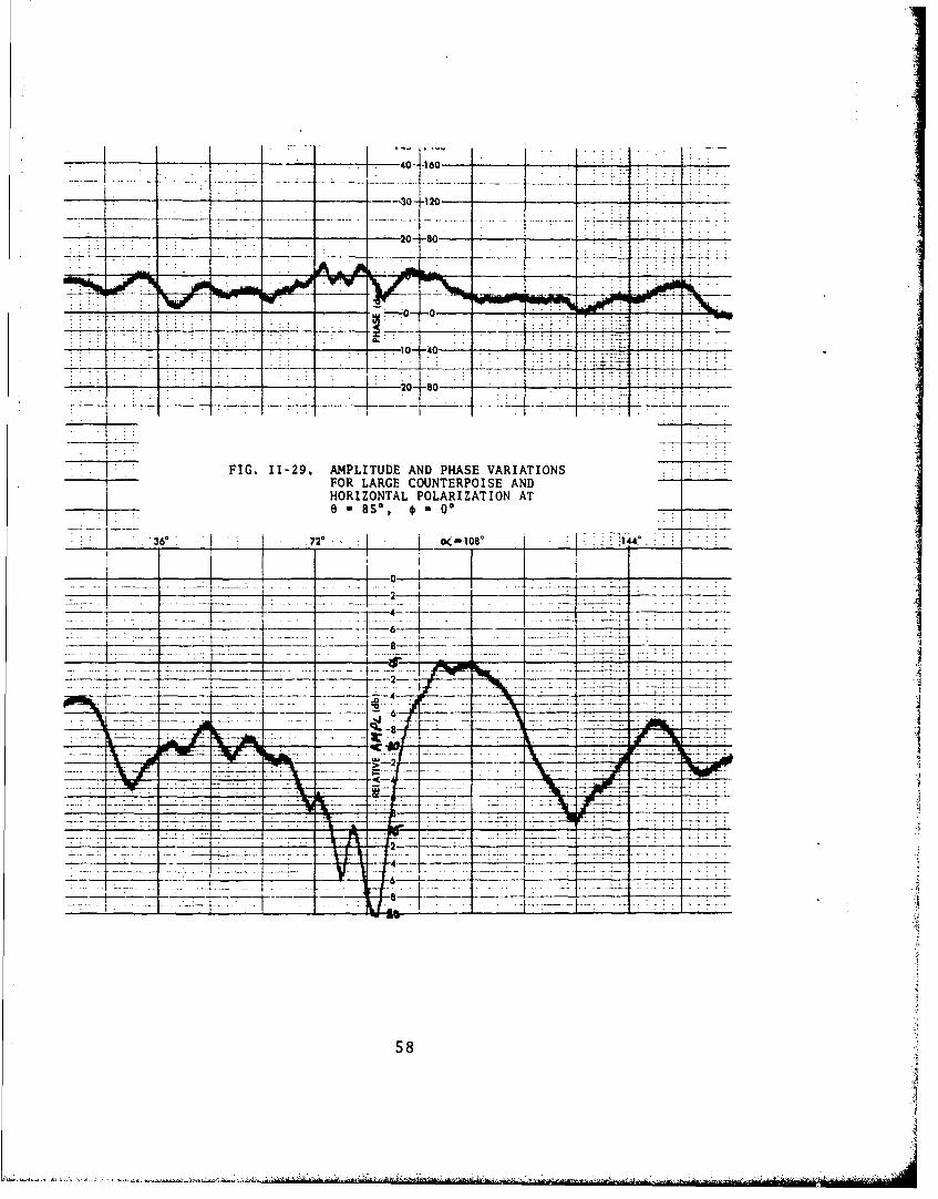
FIG. ~ ~ ~ -4 612, APIUEADPAEVRAIN
FOR 0 LAG 1ONEROS2N
FIG.1-29 HORPIZOTUEAL D POLARIZ VATIONATIN
e 8* s, * =
-- '36' ____70.oc 1080
___ 44 ___
~~ 1:72 - ______ 14 _ __
1-6-. ... . ___
-'-4 J6 __
---- -- --- . i i~r 7~
58
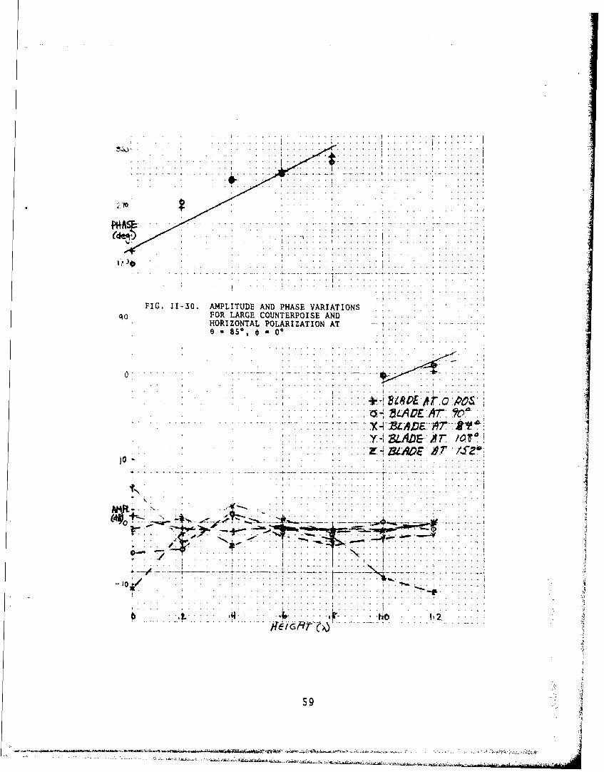
FIG. 11-30. AMPLITUDE AND PHASE VARIATIONS ,
qo. FOR LARGE COUNTERPOISE AND
. ..........
. . . . . . . . . . . . . . .. . . . . . . . .. .. .. . .
................
?J7:....7 ....... O $.............l.......--........
................................... .... ...
59

- -t4~~ 1 ov~- ~- - -
-30--120-- -
10- -40 .
.- .... 2 .
FIG. 11-31. AMPLITUDE AND PHASE VARIATIONSFOR LARGE COUNTERPOISE ANDVERTICAL POLARIZATION AT
_ _ * 2__ 108 _ _
________ _______ _______ ________I _______
-4-. -. 2_ _ __ _
-Z ----- --
60
-- - ------
:2..::~2.:..~L.:.I.2.:.:2{2:242..2 ;.......
.... .. .. ... .
t 4-
FIG. 11-32. AMPLITUDE AND PHASE VARIATIONS I .. .FOR LARGE COUNTERPOISE ANDVERTICAL POLARIZATION AT....
...............................
t .71
.. . . . . . ..~ .. .
61
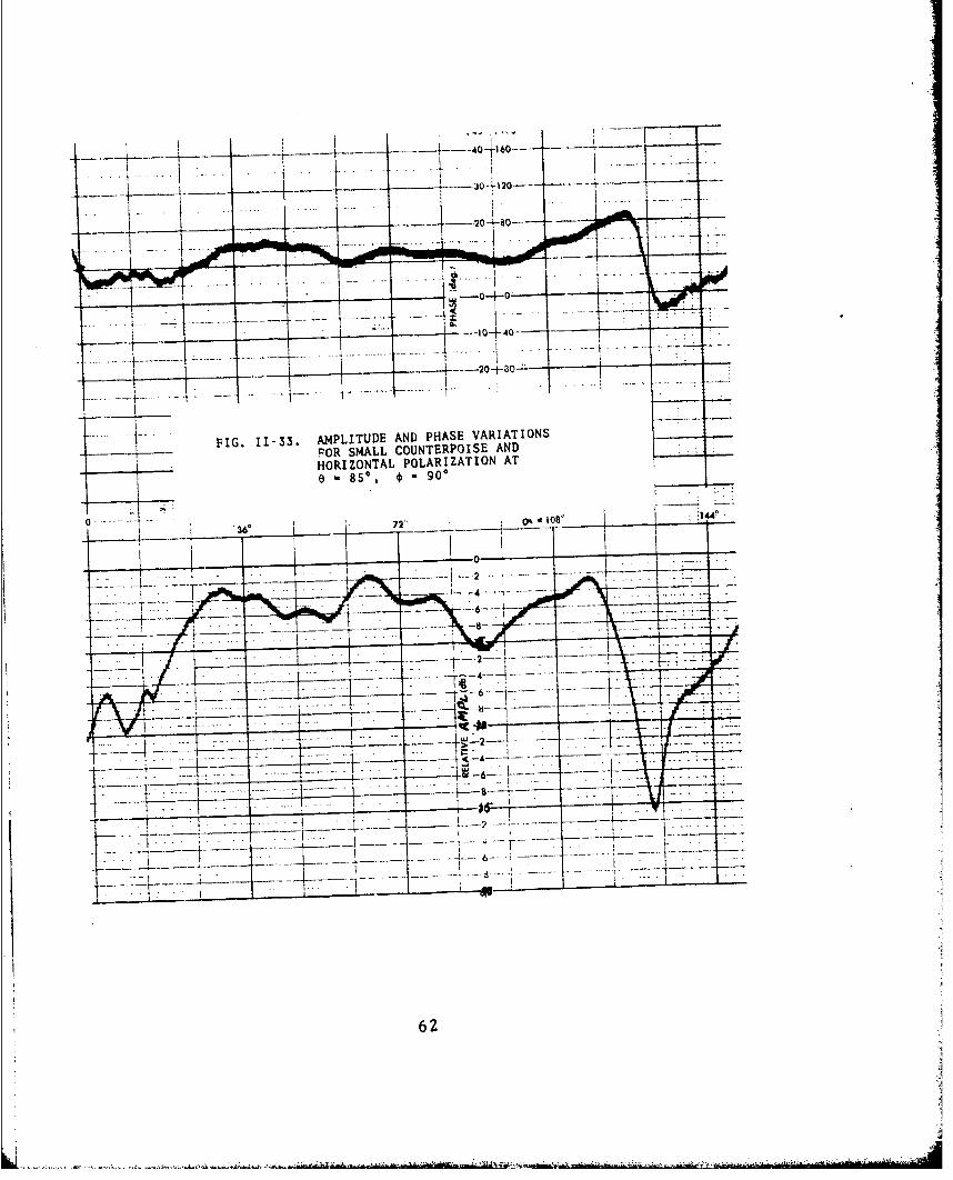
FIG. 11-33. AMPLITUDE AND PHASE VARIATIONSFOR SM4ALL COUNTERPOISE AND
HORIZONTAL POLARIZATION AT
-- ---- - 5 7 O
62
.* . .,
............... ......
PHRAE
SFIG. 11-34. AMPLITUDE AND PHASE VARIATIONS. .
FOR SMALL COUNTERPOISE AND
HORIZONTAL POLARIZATION AT .I
as' 90'
........ ..........ple1
-h.
63

-- +45~ +10- -
4 -- '-40~160- V7T . I--~ .~ii430- 120---
--- ---t 20- 18
FIG. I1-3S. AMPLITUDE AND PHASE VARIATIONSFOR SM4ALL COUNTERPOISE AND
j
VERTICAL POLARIZATION ATe so, * 900
36_ _ __ _ 72' wIIO lob4.
--- 4-----4-0 -
a -__
_ _ 4_ _ __ _
641
-.. . .- . . . . . . .. . . .-. . . . . ... . -. . ..... . . . ... .
'IWO . ...
S .... 4 ........... ... ..
(dI FIG. I1-$6. AMPLITUDE AND PHASE VARIATIONSoitFOR SMALL COUNTIERP•OISE• AND ... ...
VERTICAL POLARIZATION AT ......lirO 6 * iS•', * % 90* " ".
.. . . ..........
S.. . -.. -. -. . . I . .,. : •. .
o .. .. I
S.. . . .-- ... .
b -- i r e -..
. . . .i
*. - -~~ .: - __ Ito tl*.xi.
6S
,,3 ................ •..................... -............ ~

--- 40 i160- -
-40--4- .- ~ -..
FOR SMALL COUNTERPOISE AND
HORIZONTAL PHLASEIVARIONATION
0 8S., 1800
2:1 - -
66

-4.. 4- 4-- 1
4.•
t .
li) FIG. 11-38. AMPLITUDE AND OHASE VARIATIONS"FOR SMALL COUNTERPOISE AND......... * . . -HORIZONTAL POLARIZATION AT A
- sS,*s 0 1800, .4~**
... ..... .. . .
. . .. -. . . . . . .
4.. QW1UIAJIg~U) P
&,- *,-A
.. .. . ... .. . ... .. . . ..; .. ..
' •. ,, n . . . . i . . . . . . • . . . . . .. . . . ... . I . . . . ... . .. .. . .. . .•
S....... ... .........I -
•.. ~ ~ ~ ~ ~ r" LeIONA .OA ZTO .T ., .. ...-.
, • 8s , •- 18":: . • ....,.4 -
. .... ........
. ... .... r ... ... ... ..... . . -- ...... ... ]7 I . . ... •-.. . ...
: ::* 4 > : : : : : : : : : : :::. . . . . . . . . .
S. ... • ....... ~........"• • . •...... ,.......'"~. • ..... .................. -.--.......... ...... 4.... .. '
S..... ....... .
., ; . . . . . . .. .. . .4- ,DI • ., :
67
S... ... • . .... .. a.I,• • .# tI i,-
-40- 120
- - --- 20-4SO-
- - ~ - ____ _ -~- -- - -1 0- -40- -
VERTICAL POLARIZATION AT0 85%.~ 180*
72
-' - - - -- -- - ----- 0
-- 4- .- - .- - -- _ _
-T7
68
kiI

.. . . .. .. . . .
.. ..... . I. .
.7 . . . . .. . .. . .. .
A .e ~ * . . I
o. FIG. 11-40. AMPLITUDE AND PHASE VARIATIONS 7aFOR SMALL COUNTERPOISE AND -
VERTICAL POLARIZATION AT..e - 8s,* 1800 . ... .
.. . . .. .. 4
. . . . . . ....... . . . . .
. . . . .. .. . .1
0 VP
691
- - - -+45--+190-.-
-20- 80-t---I___
10
____ I 20 80-
-30.1120--
FIG. 11-41. AMPLITUDE AND PHASE VARIATIONS_____FOR SMALL COUNTERPOISE AND
HORIZONTAL POLARIZATION ATe=los0 , *=900
180, 1440__ ____ ~ 10B ____ 72' 316
- - _ _ _ _ _ 4-- 6I
-I---T --
70
.. ..... .....- ..- - . ..
t . .. .................................. ............ L ; . .+........... 1
* ~ ~ ~ " 4-4 -~.
.... .. .....
ti e . ... .+ .. . . .......... .
FIG I 42 AMPLITUDE AND PHASE VARIATIONS
FIG+ . 11 42 IT RP IS AND + : 4i - :+ + + .• ::
FOR SMALL COUNTERPOISE AND W.HORIZONTAL POLARIZATION AT
sloSe, 90.
*1,,
...... •.... ~ 3 st T
-_ " , • .
.4 . . . . ..+.
- Ar
_ _ ,. . .. - . --.. .- . -
,91. ' I; -iIG t" )
I
71
" ,• : +'.i +l. .

-30- f-l20-----
. ~ ._ __ ... .... oL O.... ....
FIG. 11-43. AMPLITUDE AND PHASE2 VARIATIONSFOR SM4ALL COUNTERPOISE ANDVERTICAL POLARIZATION AT6 1050,. g*90
0 -.. 360 72' ý>108 ____ 1440
ICIE--4.
* ~ -j----6-2 --------------
J-7I.77 77 .. _
I..................... 72

.1........ .. ..
T* i1G. , -44 .AL A P VARI " TI.. ...... •
. .. .. • . . . . . . . .
i, 1 4 , i . ... . . . .. .
. . . . . . . . .
_4 - -7 I
.lo Iý
Ni.1". Wc"
.2 /10
9.. .73
, . ... . .. .. .. .. , r:: ::• : : ::I-k r :-:-
.2 •,, I• 4 5,o E,,C.
___ 4 acSi
I. :9:91'
I. .-
APPENDIX III
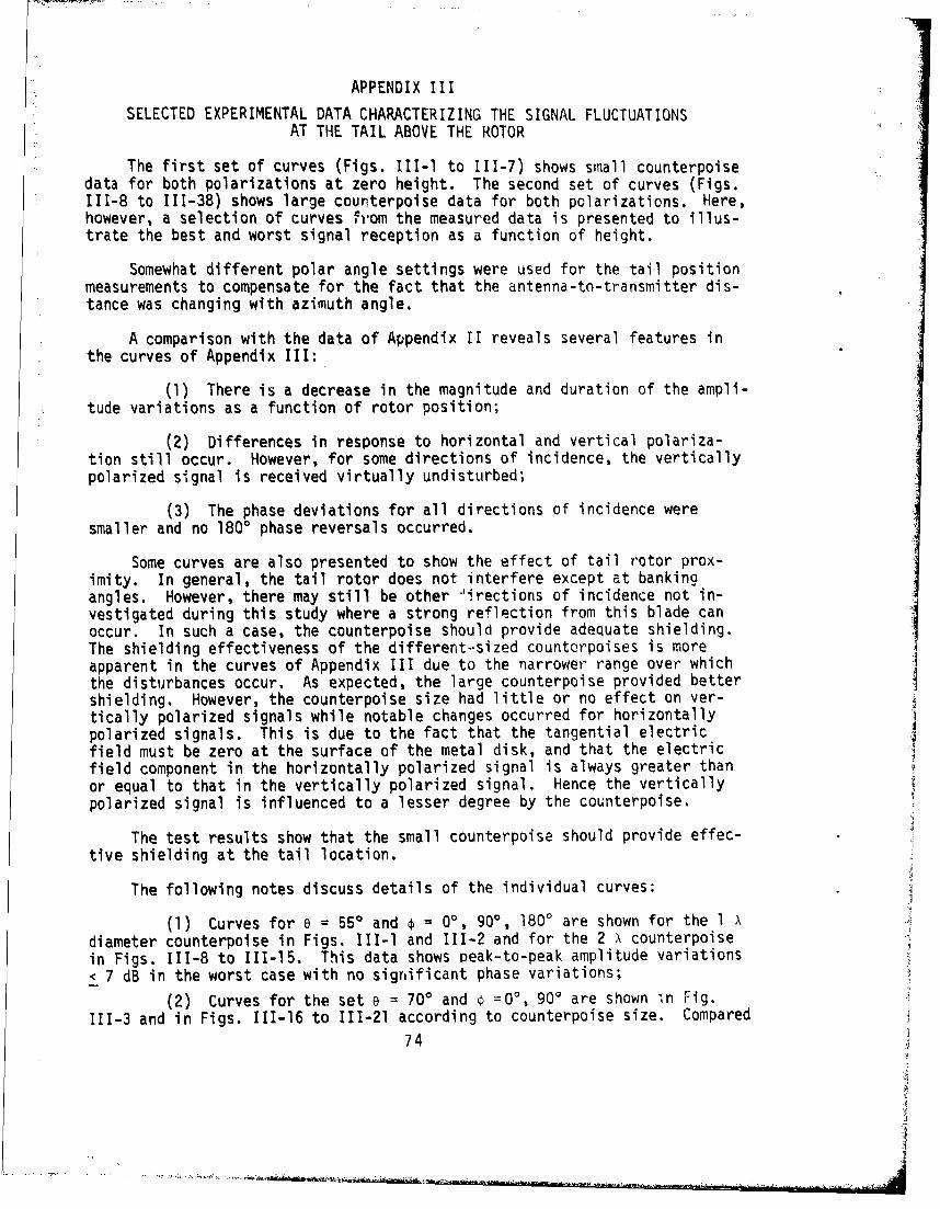
SELECTED EXPERIMENTAL DATA CHARACTERIZING THE SIGNAL FLUCTUATIONSAT THE TAIL ABOVE THE ROTOR
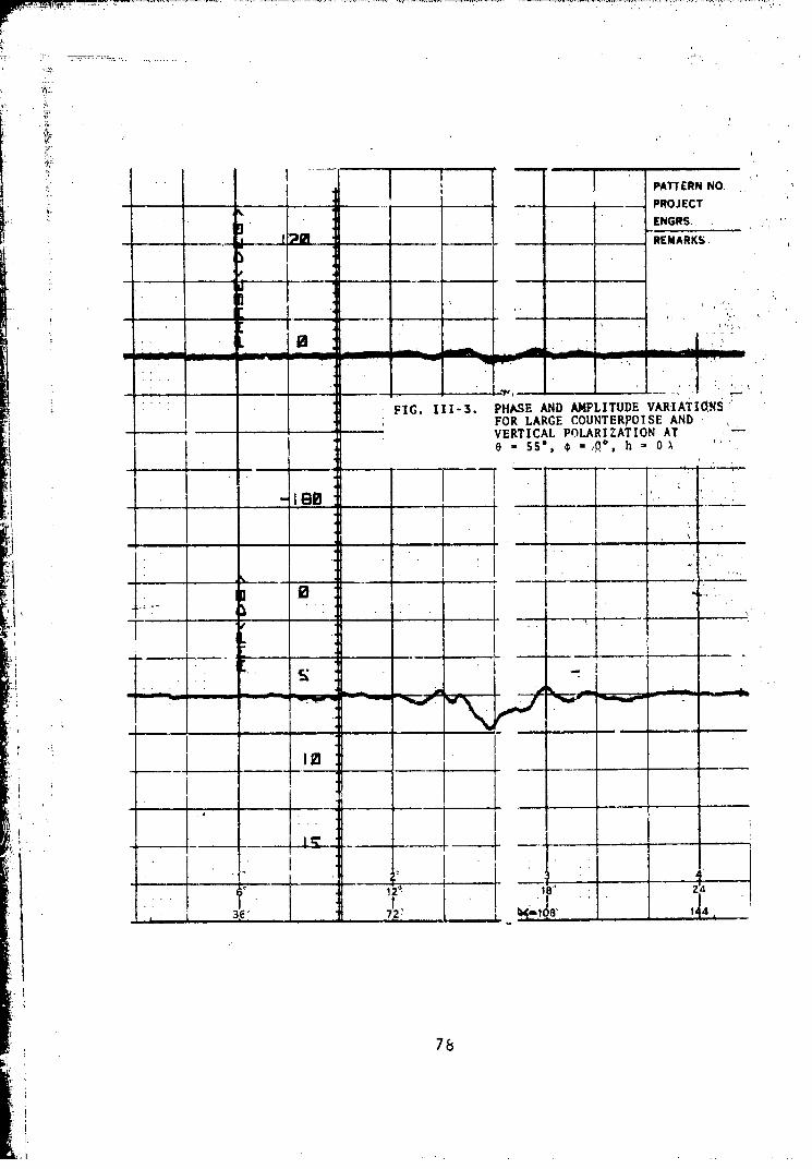
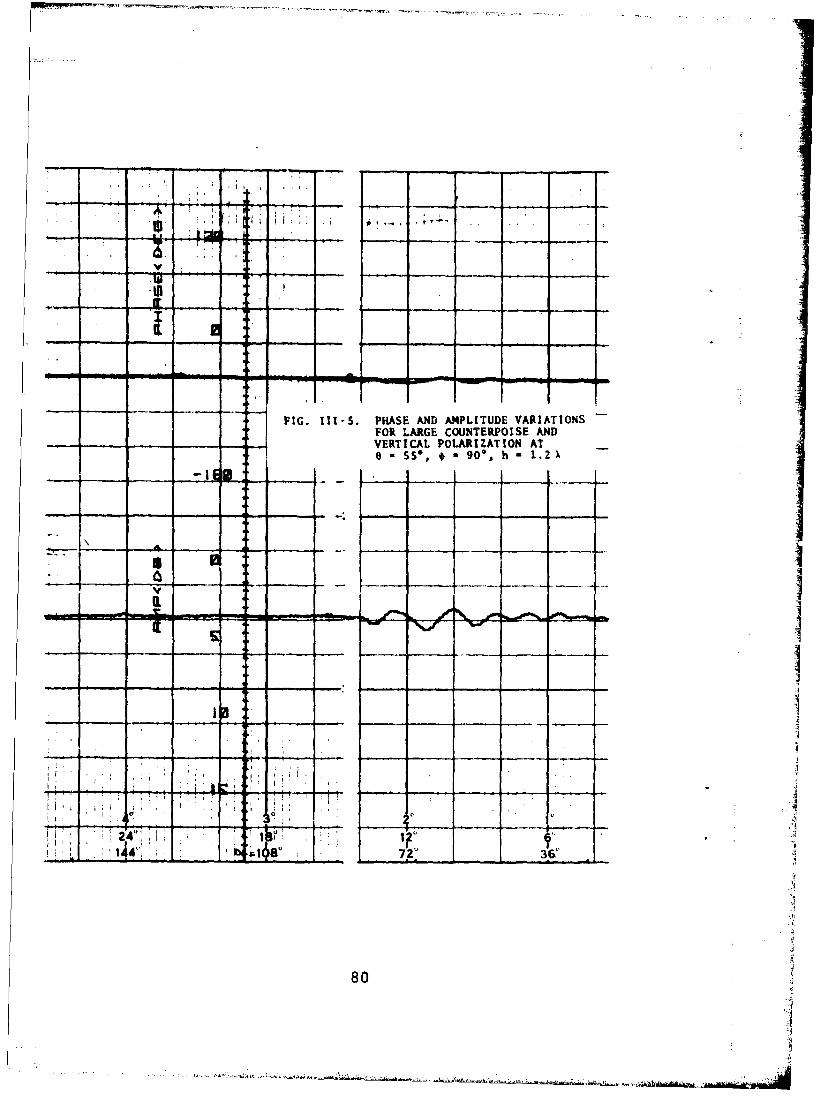
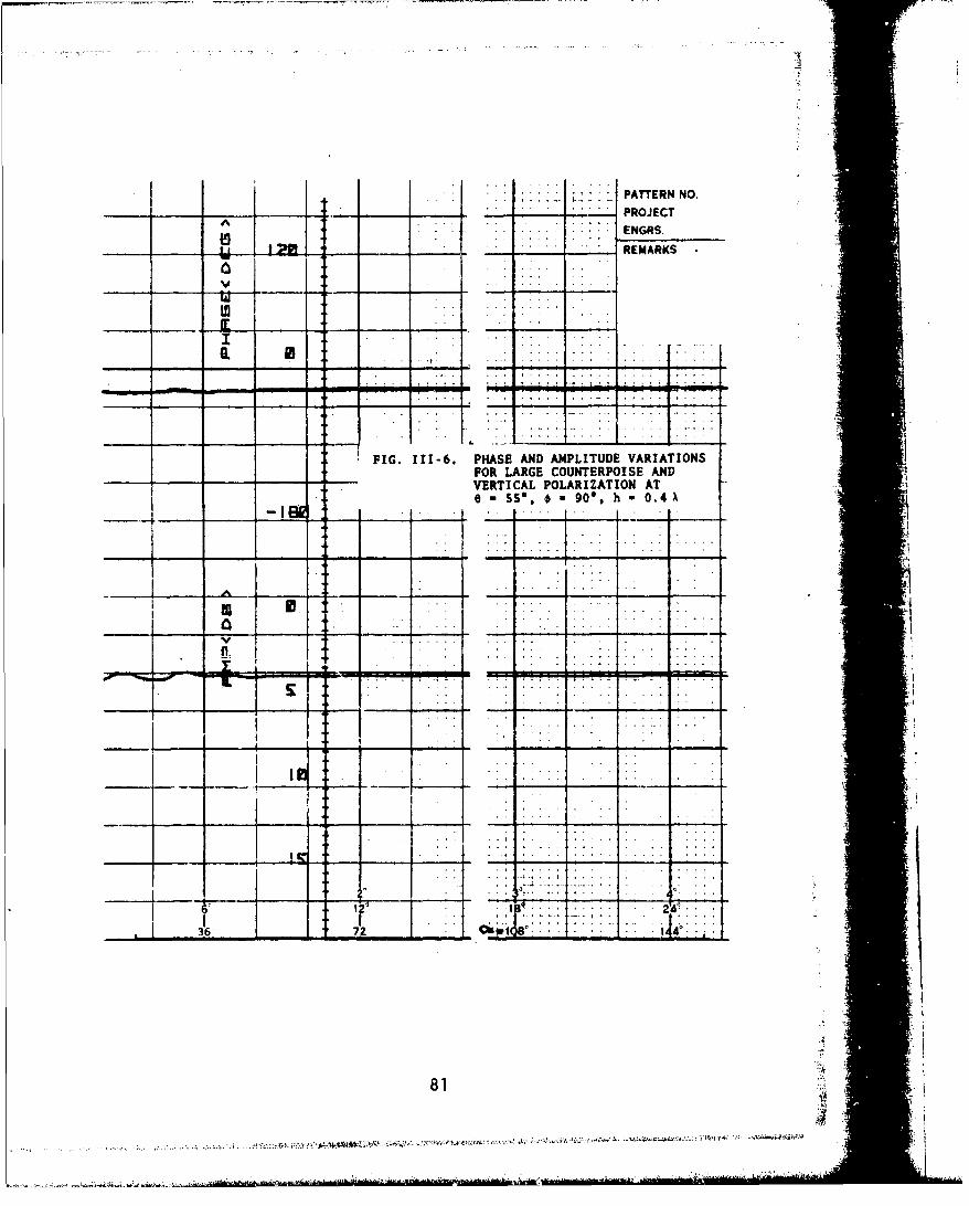
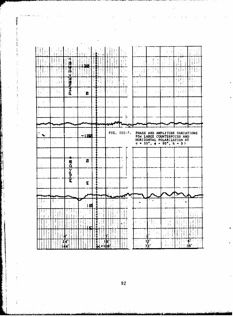
The first set of curves (Figs. III-11 to 111-7) shows small counterpoisedata for both polarizations at zero height. The second set of curves (Figs.111-8 to 111-38) shows large counterpoise data for both polarizations. Here,however, a selection of curves f'rom the measured data is presented to illus-trate the best and worst signal reception as a function of height.
Somewhat different polar angle settings were used for the tail positionmeasurements to compensate for the fact that the antenna-to-transmitter dis-tance was changing with azimuth angle.
A comparison with the data of Appendix II reveals several features inthe curves of Appendix III:
(1) There is a decrease in the magnitude and duration of the ampli-tude variations as a function of rotor position;
(2) Differences in response to horizontal and vertical polariza-tion still occur. However, for some directions of incidence, the verticallypolarized signal is received virtually undisturbed;
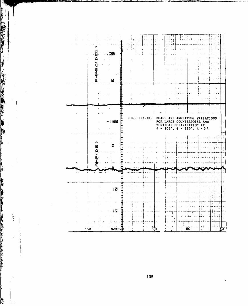
(3) The phase deviations for all directions of incidence weresmaller and no 1800 phase reversals occurred.
Some curves are also presented to show the effect of tail rotor prox-imity. In general, the tail rotor does not interfere except at bankingangles. However, there may still be other *tirections of incidence not in-vestigated during this study where a strong reflection from this blade canoccur. In such a case, the counterpoise should provide adequate shielding.The shielding effectiveness of the different-sized countorpoises is moreapparent in the curves of Appendix III due to the narrower range over whichthe disturbances occur. As expected, the large counterpoise provided bettershielding. However, the counterpoise size had little or no effect on ver-tically polarized signals while notable changes occurred for horizontallypolarized signals. This is due to the fact that the tangential electricfield must be zero at the surface of the metal disk, and that the electricfield component in the horizontally polarized signal is always greater thanor equal to that in the vertically polarized signal. Hence the verticallypolarized signal is influenced to a lesser degree by the counterpoise.
The test results show that the small counterpoise should provide effec-tive shielding at the tail location.
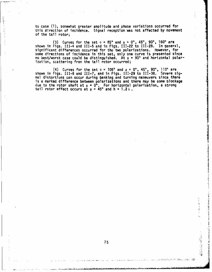
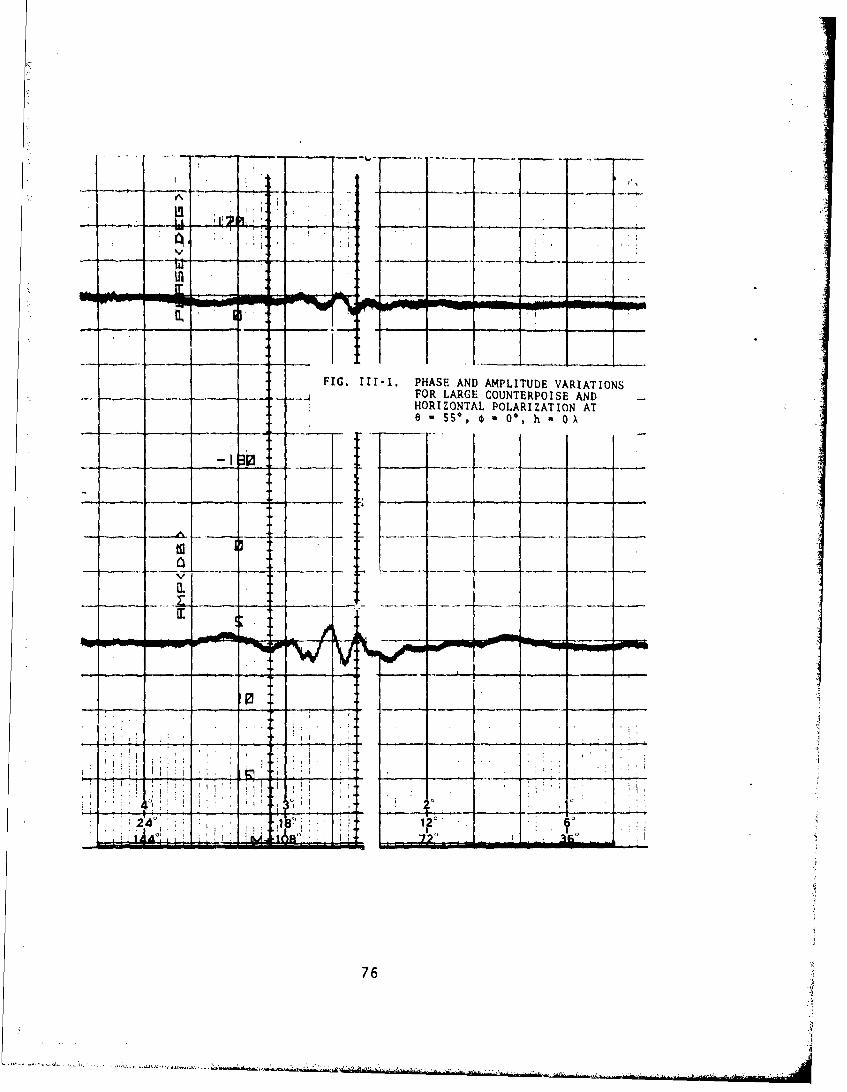
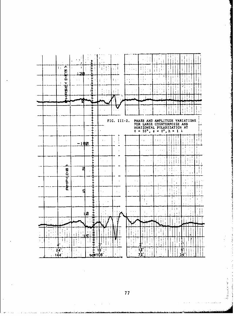
The following notes discuss details of the individual curves:
(1) Curves for e = 55' and =00, 900, 1800 are shown for the 1 Xdiameter counterpoise in Figs. II1-1 and 111-2 and for the 2 X counterpoisein Figs. 111-8 to 111-15. This data shows peak-to-peak amplitude variations< 7 dB in the worst case with no sign~ificant phase variations;
(2) Curves for the set e 700 and =0', 900 are shown ,.n Fig.111-3 and in Figs. 111-16 to 111-21 according to counterpoise size. Compared
74
to case (1,somewhat greater amplitude and phase variations occurred forthis direction of incidence. Signal reception was not affected by movementof the tail rotor;
(3) Curves for the set a 850 and o QO, 450, 900, 1800 areshown in Figs. 111-4 and 111-5 and in Figs. 111-22 to 111-28. In general,significant differences occurred for the two polarizations. However, forsome directions of incidence in this set, only one curve is presented sinceno best/worst case could be distinguished. At * - 900 and horizontal polar-izatilon, scattering from the tail rotor occurred;
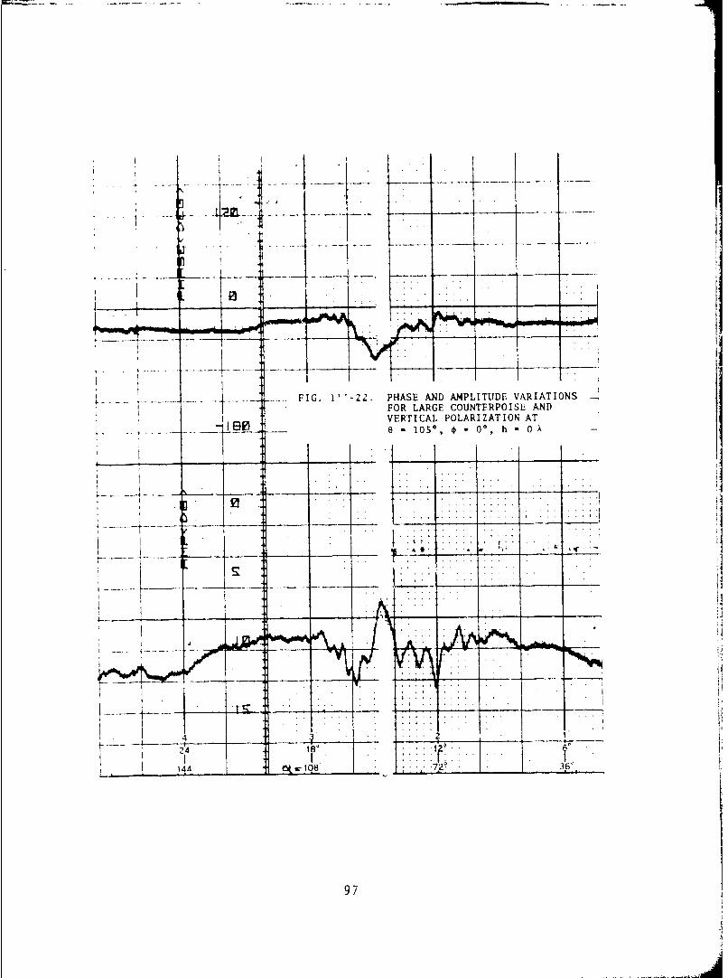
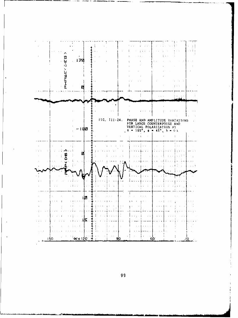
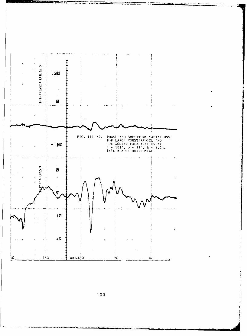
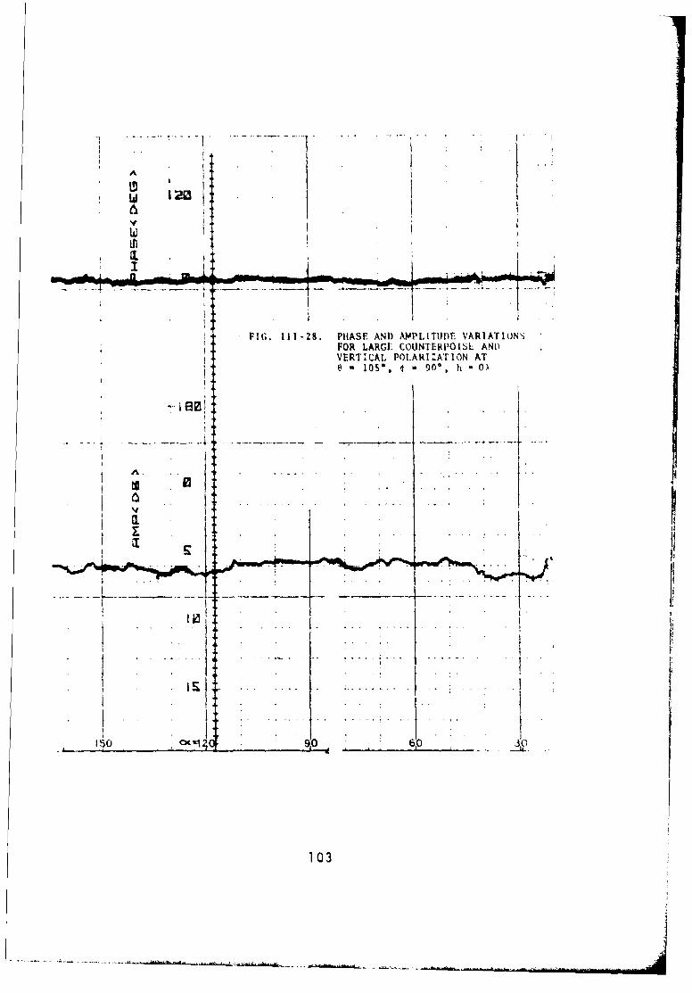
(4) Curves for the set e = l05* and o = 00, 450, 900o 1100 areshown in Figs. 111-6 and 111-7, and in Figs. 111-29 to 111-38. Severe sig-nal distortions can occur during bankipig and turning maneuvers since thereis a marked difference between polarizations and there may be some blockagedue to the rotor shaft at o a 00. For horizontal polarization, a strongtail rotor effect occurs at o - 450 and h 1.2 x.
75
IE'
FIG. 111-1. PHASE AND AMPLITUDE VARIATIONSFOR LARGE COUNTERPOISE AND
- -- HORIZONTAL POLARIZATION ATe =sso, It 0*O, h OX
.04
76
Al
S50 0% h 1I
1!JI
I Eli
lvio
4.1~ 1, hi
77
PATTERN NO.
- - _ii PROJECT1. ENGRS.
i ._,_ ,REMARKS.
FIG. 111-3. PHASE AND AMPLITUDE VARIATI.4S9"
_____ - FOR LARGE COUNTERPOISE ANDVERTICAL POLARIZATION AT
1 I e - SS' *" ,., h =0 X
IIO
•____ ___ _ - | I'
_ ii -
, .__ ___ ___ -•, . . . ,
128 2%7
76

IP
FIG. 111-4. PHASE AND AMPL~tUDE VARIATIONS_____FOR LARGE COUNTERPO ISE AND
HORIZONTAL POLARIZATION ATe s* 55 4 0% h *0.8 A
I ea--..---
j E a - -
1-2 2W72-t
79j
T-,7--
r- '- "':,, - -- L~•I - - -'. ; . . . . ..- - - - -... . . " ..
~0 . ... s. 90 hl J 1. "'; X.. ..
: • I ! . . . * . . . . . . . . . .
24"'"" .L. - - -!
FIG. Ill-S. PHASE AND AMPLITUDE VARIATIONS -
° FOR LARGE COUNTERPOJSE AND- - - =- VERTICAL POLARIZATION AT
0 " SS*, * " 90°, h = 1.2k
- p - - ~~- -£, -. . --
..4
II
I -I
- -- 4-. . . . .-
* 14 - - -72 -36'
80
, ,. '
- . -• . .
-. PATTERN NO.
- - - - - ' ' PROJECT
w ... ENGRS.
S. . - - , , REMARKS
V
S, . .-. .
T . .. . . . I. .. . .. . .. ...
FIG. 111-6. PHASE AND AMPLITUDE VARIATIONSFOR LARGE COUNTERPOISE ANDVERTICAL POLARIZATION AT6 - SS, 0 - 90', h 0 0.4 A
II
SU .. .
- I - - -I -
24L
36 7
81
81 I"
U r f O --- " .. .. " r 4 t4 A . l'
pT
I I
m FIG. 111-7. PHASE AND AMPLITUDE VARIATIONSFOA& LARGE COUNTERPOISE ANDHORIZONTAL POLARIZATION AT
0 55*, **90% h *0)
0 141i 1 '4 - 1 -1 Sl107 ' 1!
82

Ij ' ILL I ,I 1 ::
LIlI I K,, II! •' i *4- :. fl I i jiI
, IT. . . . ,1 ' ' il1 1
-• - LL I il • i l l
-i- '.' 1A
FIG. II-8. PHASE AND AMPLITUDE VARIATIONSFOR LARGE COUNTERPOISE AND _HORIZONTAL POLARIZATION AT' .- e- SSo, * = 1800, h 0 X
I - • - - - . . .. -... . ..
toi
, J ,
-, V -i-, -
I - - -
240
' - .. . - - -- -• - -•--- - ..- ,-*
" 1 ! :~ : . . :"1 i
83

i FIG. 111-9. PHASE AND AMPLITUDE VARIATIONSFOR LARGE COUNTERPOISE AND
-r-t+HORIZONTAL POLARIZATION AT
70*I 0i h 0
10J I L H
84

*II I FIG. II1-10. PHASE AND AMPLITUDE VARIATIONSFOR LARGE COUNTERPOISE AND
HORIZONTAL POLARIZATION AT
w 0
85

S ... ... . .. ......... !
- -.- 0-.- --, b- - -
. . 14 4-. . ... . . . .
g,
.... .. .FIG. -8 . PHASE AND APLITUDE VARIATIONS-... .... FOR LARGE COUNTERPOISE AND
S...... ....... VERTICAL POLARIZATION ATr,- •-:.,ii :i: , -i:.......e -. ?0,• * - 0', b " 0
U. "
_ _ _I I
14'" ___ __,, _ "_____ ... 36"
86

- - -.- --- - . - ~ A) P -A
tf~
4-i
FI.111-12. PHASE AND AMPLITUDE VARIATIONS
e -70% * 0%O h -0.4 A~
-4 - 1
i441
111 tp N_4Hz- - ~ - a

- - - - - - - . ~ PROJECT
.1 .IG .1-3 PHS A .A .LTD VARIATIONS. . ..
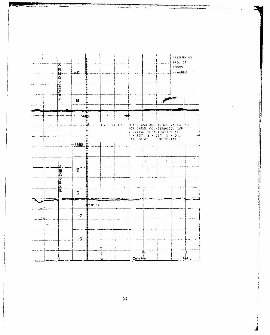
.. .... FOR LARGE COUNTERPOI SE AND- - - -VERTICAL POLARIZATION AT
8 - 70% * 90% h a 1.Z )TAIL BLADE: HORIZONTAL
- - - - - -- -m
. . . .. -. . -.-.-- - w
-. . -. . -..--
tip..
-. Z2~ )24
88

: pPATTERN NO.__~~ -.....- 'T PROJECT
':.:; ENGRS.
- - - ....- ~....,.. REMARKS
- - - -
FIG. 111-14. PHASE AND AMPLITUDE VARIATIONSFOR LARGE COUNTERPOISE AND
-- - - -VERTICAL POLARIZATION AT6 - 700, *a90% h 2 ATAIL BLADE: VERTICAL
. .. . .. . . . . ..
12 -24....~ 41---- . ~- ........ -
4. 4- 4- *...........i

PATTERN NO.- - - - PROJECT
ENGRS.-- - - - *- - REMARKS
*mm -or
-rr
- ______ - - - i ---
... .~ . -., .. . . .
... .... .-2I.111. PAEADAPIUEVRAIN
44 -
----- I 90
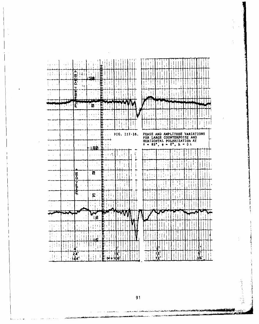
FIG. 111-16. PHASE AND AMPL1TUDE VARIATIONSFOR LARGE COUNTERPOISE AND
- 'HORIZONTAL POLARIZATION AT... .. 8SO, 00,O" h 0
Ilk
I IlI
Flo I
I4 7
V9

FIGI. I11-17. PHASE AND AMPL ITUDE VARIATIONSFOR LARGE COUNTERPOISE ANDHORIZONTAL POI.ARIZATION AT
-~~ 9 - 8S*, -900, h - 1.2 ~TATIL BLADE: IORI ZGNTAL
92

II. [IIL 0
IFIG. III le, PHASF. AND AMPLITUDF VARIATIONS
I 4FOR LARGE COUNTERPOISEL AND i
I I
K. ...........A... !
21 1'2 6-._...__ .. 108 72" . 3
93
PAMl RN NO
-~. . .PROJECT
L9 FN(;PRS
4.........Rý MARKc,
I P
-- -- ,.-.. .. ~----..~- . f I~. Ii 1. 1HASI. AND) AMP!. ID T1 .["OR LARGI. (B3UN rRPOI SI ,NDVlERTICAL. PoLARI ZAr IOfN AT
-~~ ..- 85*, ý - 9O*, h) - 0 .
TAT!. RLA ii: Ir i RI Z ONTA 1
to --..---
-- - ~~12_ I24
72____ 144__
_______94

"'AT~rRN NOI PROJECTFNGRSREMARKS
I i-
Ln
- I -I"
- FIG. 111-20. PHASE AND AMPLITUDE VARIATIONS
.. .... - FOR LARGE COUNTERPOISE ANDI,, VERTICAL POLARIZATION AT
- I E I 0 8 - , !) o , h0 - 0
1I jl
_.. .. . __.. .. .____- _____ - -. -- .---- .- .- '
*.. .. . 0 . / '
--4.----- -
I -
, --A - 7 , •5
95

...... ....
7.... ...
F IG 11 -1 W 1 .i AMPLIHIN VArUDE(NFRLAR(,I COUNTIRPOI SI AND
VIRr(Al, ll(UARI ,A'IION AT
I E3 rd 80 18C, h1 - O
IL'
t*
Vt 44 _ 72' 36
96
' ! 1 - --"
- - - -' - -
S.......... ---- -t- ---- - - 7 -. . - -
. . . . .FIG. 1'-22. PHASE AND AMPLITUDE VARIATIONS* FOR LARGE COUNTERPOISE AND
VERTICAL POLARIZATION AT-e - 1 5 , - 0°, h 0 0 ,x,
I - -... ,--.. . . . .. . .. . ... . . . . . -----
I' ______
_ _I __ _. .. . . . . . .
--.. -.... - .------ -------V----- ----..- F I--a j
4 .. •.. . ... 2 _,_ _-• '
241'
________.... V)4A98 -70
97
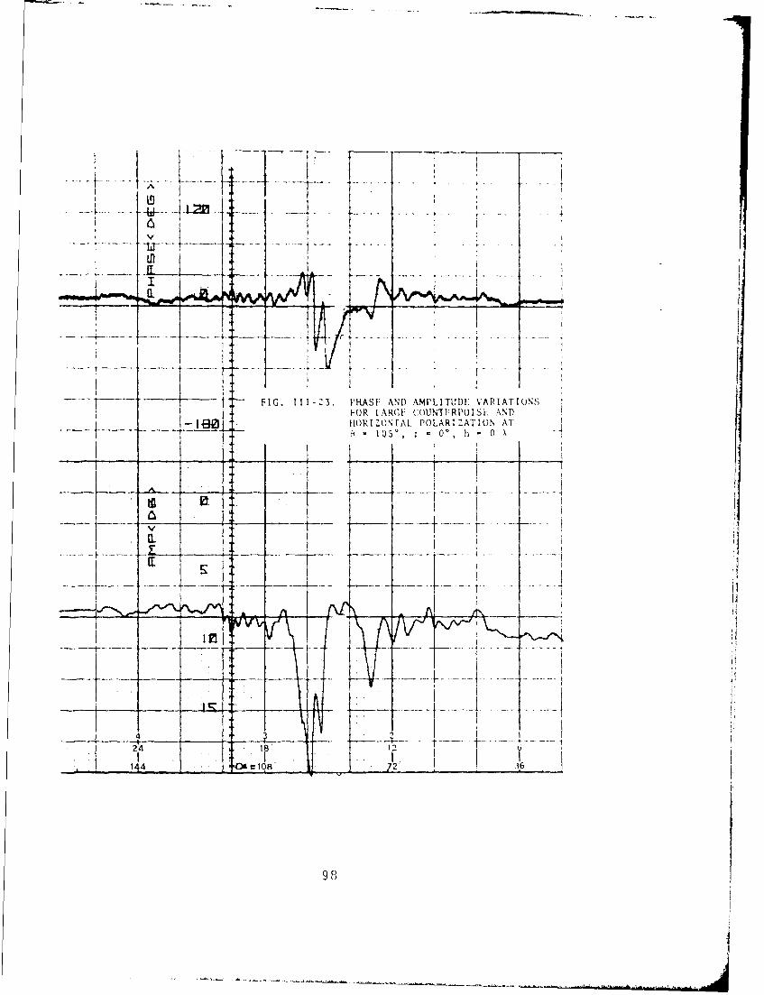
FIG. 111-23. PHASI: AND AMPLITUDE VARIATIONSFOR IAG OLNTYRPOIS AND
fi(RlC)NI'l.POLARI ZAT ION A
0 '0 , h - 0 X
_____ --k
14 v_ I_- ~~
9 P
AgA
FIG. 111-24. PHASE AND AMPLITUDE VARTUAHONSFOR LARGE COUNTERPOISE ANDVERTICAL POLARIZATION Al
-l8l 10lS*, * 450, h 0 kX
99
In'
EL~ 0
FIG. 111-2S. PHASE AND AMPLITUDIU VAN1ATIONSIFop LARG: COtJN'rFRfl) S[: -W)I FI~ORIZZONrAL POLAR I:AT ION .T
A IO5*, 4' - 4S*. h - 2 ITAIL1 BLADE: HIORI ZONTAL
C. i
100

FI.112.PHS N MLTUEVRAIN
HORIZONTAL POLARI'ATION AT0 - 10W, s - 45*, h 1. *
TAIL BLADE: VERTICAL
150 o90 6
101

KIIn
FIG. 111-27. PHASE AND AM4PLITUDE VARIATIONS60FOR LARGE COUNTERPOISE AND
HORIZONTAL POLARIZATION ATI e-O~.ShO ,
1.... W. h 0 X
KI
10' CI 0 90 60 39
102
LA
ni
FIG. 111-28. PHASE AND AMPLITUDE VARIATItO)NFOR LARGI COUNTERPOISL ANDVERTICAL POLARI:ATION ATe ,, f W . 11 h -
4 3
I .I
i ° . .............
I 5 0 . . . . .._•_.. . . . . . . . . . -. .
103
-.. - ~ - ~~-~-

'IL
FI.112. PHS NIMLTUEVRAINFU LAG CUTEPIS N
HOIONA POAIZTONA
10 * 4; 90 ,h
At . - -4L~-~-..
1 04
...... ., ..
FOR7
FIG. 111-30. PHASE AND AMPLITUDE VARIATIONS-113 FORLARGE COUNTERPOISE AND
I VERTICAL POLARIZATION ATj8 1 0S',* 110% h 0 X
-~.-.... ... . ... ...
.. V~II 10
105

-IG 11-31 - HS- ADAMLTUE-AIT-N
. . . . . . . . . . . . . . . . . . . . . . . . . .. . . . . . . . .
-IO HOIONA POAIZTO AT
6!~ 10I, 11",h
VJ
41
I106

7 7 :--7-.6-7 7-
. 20t80 -A
I. 07774h..
FIG. 111-32. PHASE AND AMPLITUDE VARIATIONSFOR SMALL COUNTERPOISE ANDHORIZONTAL POLARIZATION AT8 SS*,*450, h 0OA
___ki __ _ __ -t- -
11
-6
.~~ . . ... .
T- --- 7~
_7_'-_ -7 7
107

:-107 40-
. .. . . 30- 10 -
FIG. .1-3 PHS AN AMLTD VAITIN
FOR SMALL COUNTERPOISE ANDVERTICAL POLARIZATION AT
:720 ___
_______. - .----- .- .. - . ..
-.. .... . .. ..- -- -- .-- - - -- -
r-Iý
-10Z 4.4 4 -
108

-I0 6 - - ---
1. --- 20- 80--ý-
FIG. 111-34. PHASE AND AMPLITUDE VARIATIONS-- FOR SMALL COUNTERPOTSY AND
VFRTICAL POLARIZATION AT
e-7O 0 ,-77-7-
I-4
2- - -- 7 7-'-1
.--.. 4--
I. 6--_------------- - - -t - .-- - -.... . -.j.....
109
.0" 0 . . . .
... . .. .. .
-10- -A0---
, - 8 0 - - - --120
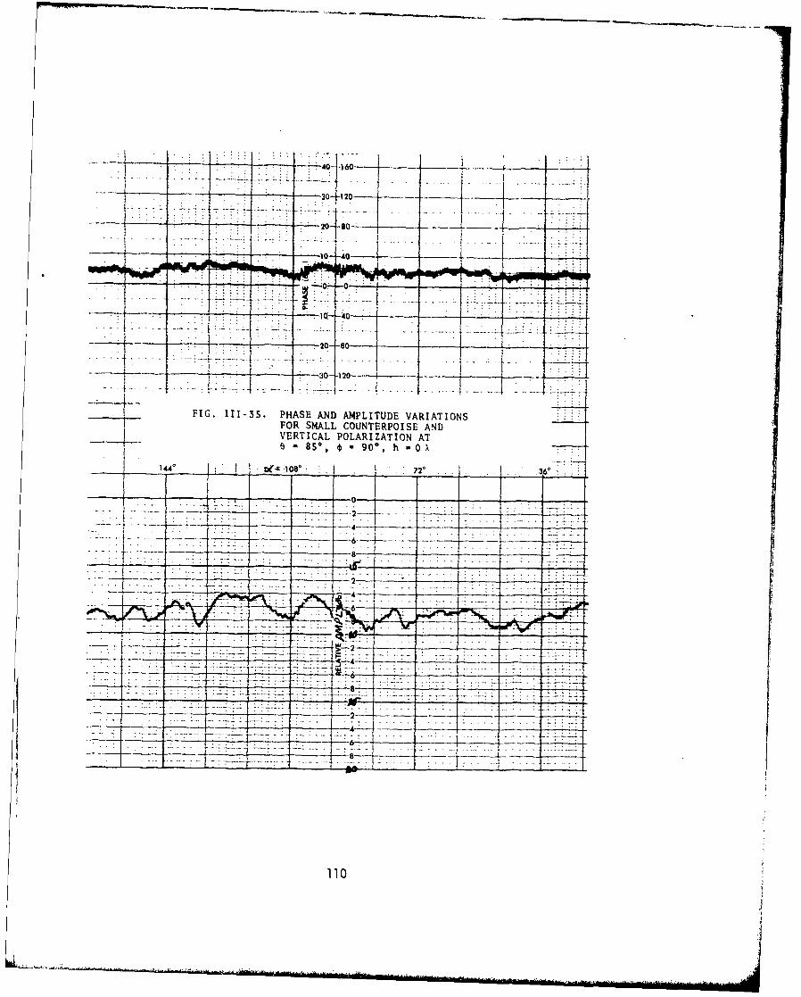
*FIG. 111-35. PHASE AND AMPLITUDE VARIATIONSFOR SMALL COUNTERPOISE ANDVERTICAL POLARIZATION AT6 -85% 0 90*, h -O0X
1 0 72q
2
-- _ -------- 2-
110
- ~ ~ f I *45- 1+Ibu-r---T r-
I - 71 - --4
-- h--- --- 0-480- -
-i I -~-30- 19C~
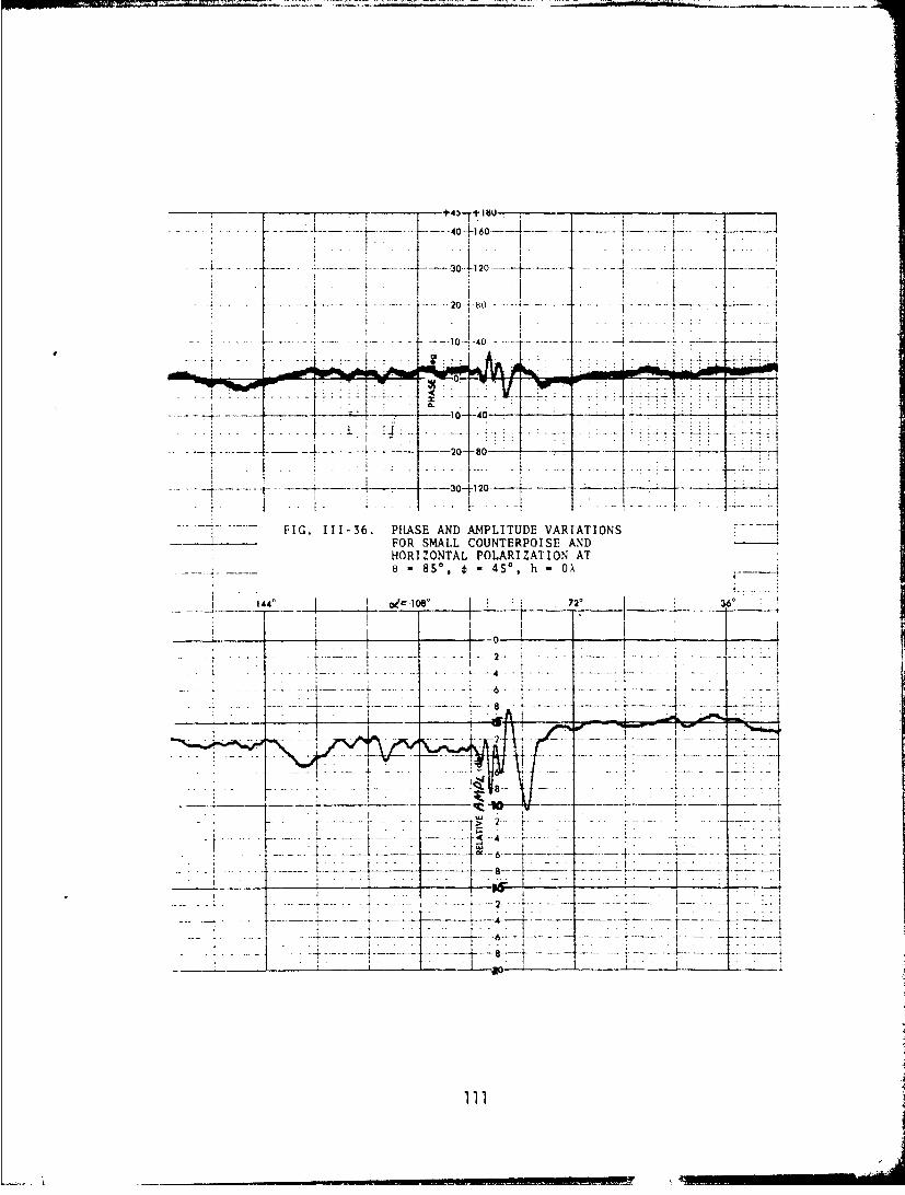
FIG. 111-36. PHASE AND AMPLITUDE VARIATIONS - -
----- 4-FOR SMALL COUNTERPOISE AND
HORIZONTAL POLARIZATION ATe=8S-, *=450, h *OX
___144' ~ oec108' -2 36*
I--4
_________________ _____ _____ I __-6_
-'-~ -
8 -- - -
-{ -- ----4--.------ --.- t
-___ _ I ____ ____ _ L ________10__
I ~~~30 120-.-t.---.
- - .10- ------0
---- ~ --- ---- --- -- -14 4 - -_ - -_
T_ 1 0 -4 -i . --------
-3-0-T10
.~ . ... . . . .
. . . . ..- . . . . . ....
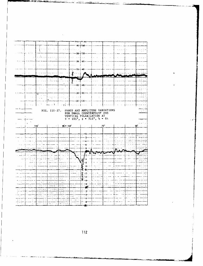
FI.7-4 - HSEADAPLTD ARAIN
FOR SALL OUNTRPOI7-AN
VETIALPOAR1 AIO2A
4- 60io--
-20 _ _1
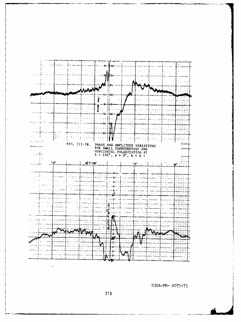
F~r.11138.PHASE AND AMPLITUDE VARIATIONSFOR SMALL COUNTERPOISE ANDHORIZONTAL POLARIZATION AT
1 0 " J O Y 0 0 , h - 0 X~
1440 (.o 2*2. 6___
i144. .7 .. 1 .....v-li-z- 6 ~ ~ -
HISA-FM- 2075-75 .
113