1701368€¦ · web view5.2.2.6.2.the word "isofix" in capital letters of ... the...
TRANSCRIPT

E/ECE/TRANS/505/Rev.3/Add.144
4 September 2018
Agreement
Concerning the Adoption of Harmonized Technical United Nations Regulations for Wheeled Vehicles, Equipment and Parts which can be Fitted and/or be Used on Wheeled Vehicles and the Conditions for Reciprocal Recognition of Approvals Granted on the Basis of these United Nations Regulations*
(Revision 3, including the amendments which entered into force on 14 September 2017)
_________
Addendum 144 – UN Regulation No. 145
Date of entry into force as an annex to the 1958 Agreement: 19 July 2018
Uniform provisions concerning the approval of vehicles with regard to ISOFIX anchorage systems ISOFIX top tether anchorages and i-Size seating positions
This document is meant purely as documentation tool. The authentic and legal binding text is: ECE/TRANS/WP.29/2017/133.
_________
* * Former titles of the Agreement:Agreement concerning the Adoption of Uniform Conditions of Approval and Reciprocal Recognition of Approval for Motor Vehicle Equipment and Parts, done at Geneva on 20 March 1958 (original version);Agreement concerning the Adoption of Uniform Technical Prescriptions for Wheeled Vehicles, Equipment and Parts which can be Fitted and/or be Used on Wheeled Vehicles and the Conditions for Reciprocal Recognition of Approvals Granted on the Basis of these Prescriptions, done at Geneva on 5 October 1995 (Revision 2).

E/ECE/324/Rev.2/Add.139E/ECE/TRANS/505/Rev.2/Add.139
UNITED NATIONS
2

UN Regulation No. 145
3

ECE/TRANS/WP.29/2017/133
Uniform provisions concerning the approval of vehicles with regard to ISOFIX anchorage systems ISOFIX top tether anchorages and i-Size seating positions
ContentsPage
1. Scope ........................................................................................................................................ 4
2. Definitions ................................................................................................................................ 4
3. Application for approval .......................................................................................................... 7
4. Approval ................................................................................................................................... 7
5. Specifications ........................................................................................................................... 8
6. Tests ......................................................................................................................................... 14
7. Modifications and extension of approval of the vehicle type .................................................. 17
8. Conformity of production ......................................................................................................... 18
9. Penalties for non-conformity of production ............................................................................. 18
10. Production definitively discontinued ....................................................................................... 18
11. Names and addresses of Technical Services responsible for conducting approval tests, andof Type Approval Authorities .................................................................................................. 19
Annexes
1 Communication......................................................................................................................... 20
2 Arrangements of the approval mark ......................................................................................... 22
3 Procedure for determining the "H" point and the actual torso angle for seatingpositions in motor vehicles........................................................................................................ 23
Appendix 1 - Description of the three-dimensional "H" point machine (3-D H machine)...... 23Appendix 2 - Three-dimensional reference system ................................................................. 23Appendix 3 - Reference data concerning seating positions...................................................... 23
4 ISOFIX anchorages systems and ISOFIX top tether anchorages............................................. 24
5 i-Size seating position............................................................................................................... 35
4
E/ECE/TRANS/505/Rev.3/Add.144
1. Scope
This Regulation applies to:
(a) Vehicles of category M1 with regard to their ISOFIX anchorage systems and their ISOFIX top tether anchorages intended for child restraint systems. Other categories of vehicles fitted with ISOFIX anchorages have also to comply with the provisions of this Regulation;
(b) Vehicles of any category with regard to their i-Size seating positions, if any are defined by the vehicle manufacturer.
2. Definitions
For the purposes of this Regulation,
2.1. "Approval of a vehicle" means the approval of a vehicle type with regard to the ISOFIX anchorage systems, the ISOFIX top tether anchorages, and i-Size seating positions if any;
2.2. "Vehicle type" means a category of power-driven vehicles, which do not differ in such essential respects as the dimensions, lines and materials of components of the vehicle structure or seat structure to which the ISOFIX anchorages systems and ISOFIX top tether anchorages if any are attached and, if the anchorages strength is tested according to the dynamic test, as well as the vehicle floor strength when tested according to the static test in case of i-Size seating positions, the characteristics of any component of the restraint system, especially the load limiter function, having an influence on the forces applying to the anchorages.
2.3. "Floor" means the lower part of the vehicle body-work connecting the vehicle side walls. In this context it includes ribs, swages and possibly other reinforcements, even if they are below the floor, such as longitudinal and transverse members;
2.4. "Seat" means a structure which may or may not be integral with the vehicle structure complete with trim, intended to seat one adult person. The term covers both an individual seat or part of a bench seat intended to seat one person;
2.5. "Front passenger seat" means any seat where the "foremost H point" of the seat in question is in or in front of the vertical transverse plane through the driver's R point;
2.6. "Group of seats" means either a bench-type seat, or seats which are separate but side by side (i.e. with the foremost anchorages of one seat in line with or forward of the rearmost anchorages and in line with or behind the foremost anchorages of another seat) and accommodate one or more seated adult person;
2.7. "Bench seat" means a structure complete with trim, intended to seat more than one adult person;
2.8. "ISOFIX" is a system for the connection of child restraint systems to vehicles which has two vehicle rigid anchorages, two corresponding rigid attachments
5

E/ECE/TRANS/505/Rev.3/Add.144
on the child restraint system and a mean to limit the pitch rotation of the child restraint system.
2.9. "ISOFIX position" means a position which allows the installation of:
(a) Either an universal ISOFIX forward facing child restraint system as defined in UN Regulation No. 44;
(b) Or a semi-universal ISOFIX forward facing child restraint system as defined in UN Regulation No. 44;
(c) Or a semi-universal ISOFIX rearward facing child restraint system as defined in UN Regulation No. 44;
(d) Or a semi-universal ISOFIX lateral facing position child restraint system as defined in UN Regulation No. 44;
(e) Or a specific vehicle ISOFIX child restraint system as defined in UN Regulation No. 44;
(f) Or an i-Size child restraint system of integral class as defined in UN Regulation No. 129;
(g) Or a specific vehicle ISOFIX child restraint system as defined in UN Regulation No. 129.
2.10. "ISOFIX low anchorage" means one 6 mm diameter rigid round horizontal bar, extending from vehicle or seat structure to accept and restrain an ISOFIX child restraint system with ISOFIX attachments.
2.11. "ISOFIX anchorages system" means a system made up of two ISOFIX low anchorages which is designed for attaching an ISOFIX child restraint system in conjunction with an anti-rotation device.
2.12. "ISOFIX attachment" means one of the two connections, fulfilling the requirements of UN Regulation No. 44 or UN Regulation No. 129, extending from the ISOFIX child restraint system structure and compatible with an ISOFIX low anchorage.
2.13. "ISOFIX child restraint system" means a child restraint system, fulfilling the requirements of UN Regulation No. 44 or UN Regulation No. 129, which has to be attached to an ISOFIX anchorages system.
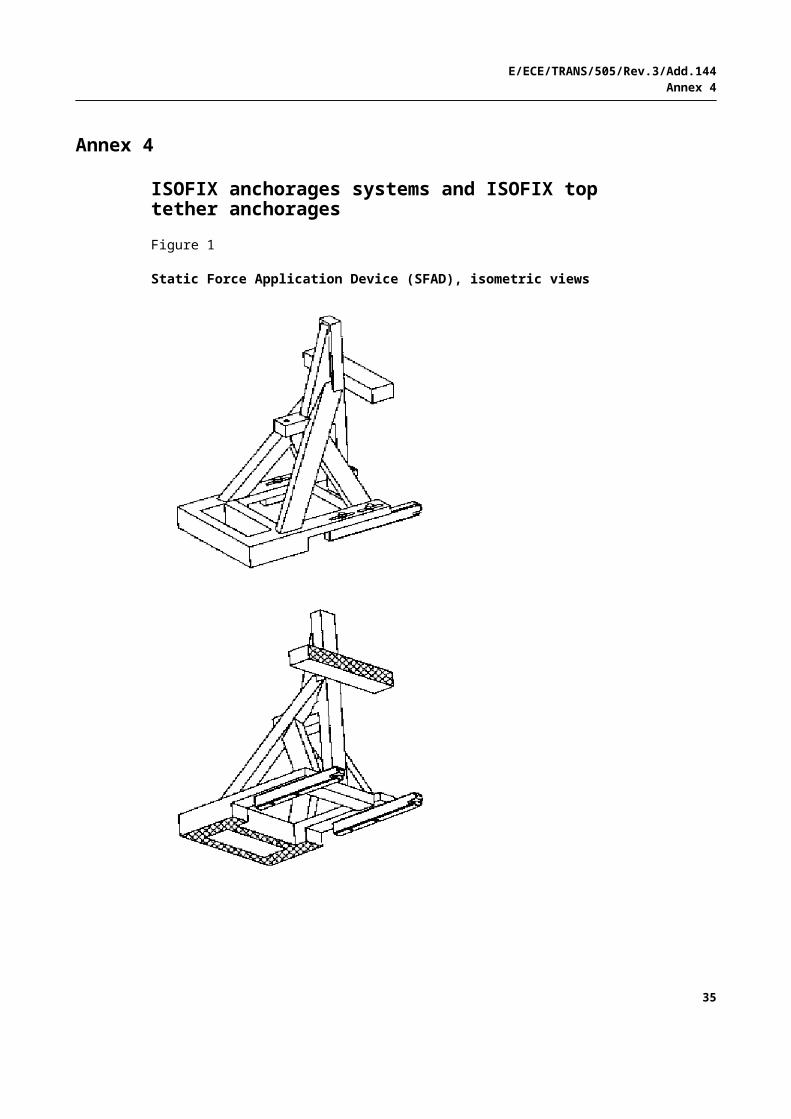
2.14. "Static force application device (SFAD)" means a test fixture that engages the vehicle ISOFIX anchorages systems and that is used to verify their strength and the ability of the vehicle or seat structure to limit the rotation in a static test. The test fixture for lower anchorages and top tethers is described in the Figures 1 and 2 Annex 4, as well as an SFADSL (Support Leg) to assess i-Size seating positions with regard to the vehicle floor strength. An example for such an SFADSL is given in Figure 3 of Annex 5.
2.15. "Anti-rotation device":
(a) An anti-rotation device for an ISOFIX universal child restraint system consists of the ISOFIX top-tether;
(b) An anti-rotation device for an ISOFIX semi-universal child restraint system consists of either a top tether, the vehicle dashboard or a support leg intended to limit the rotation of the restraint during a frontal impact;
6

E/ECE/TRANS/505/Rev.3/Add.144
(c) An anti-rotation device for an i-Size child restraint system consists of either a top tether or a support leg intended to limit the rotation of the restraint during a frontal impact;
(d) For ISOFIX, i-Size, universal and semi-universal, child restraint systems the vehicle seat itself does not constitute an anti-rotation device.
2.16. "ISOFIX top tether anchorage" means a feature, such as a bar, located in a defined zone, designed to accept an ISOFIX top tether strap connector and transfer its restraint force to the vehicle structure.
2.17. "ISOFIX top tether connector" means a device intended to be attached to an ISOFIX top tether anchorage.
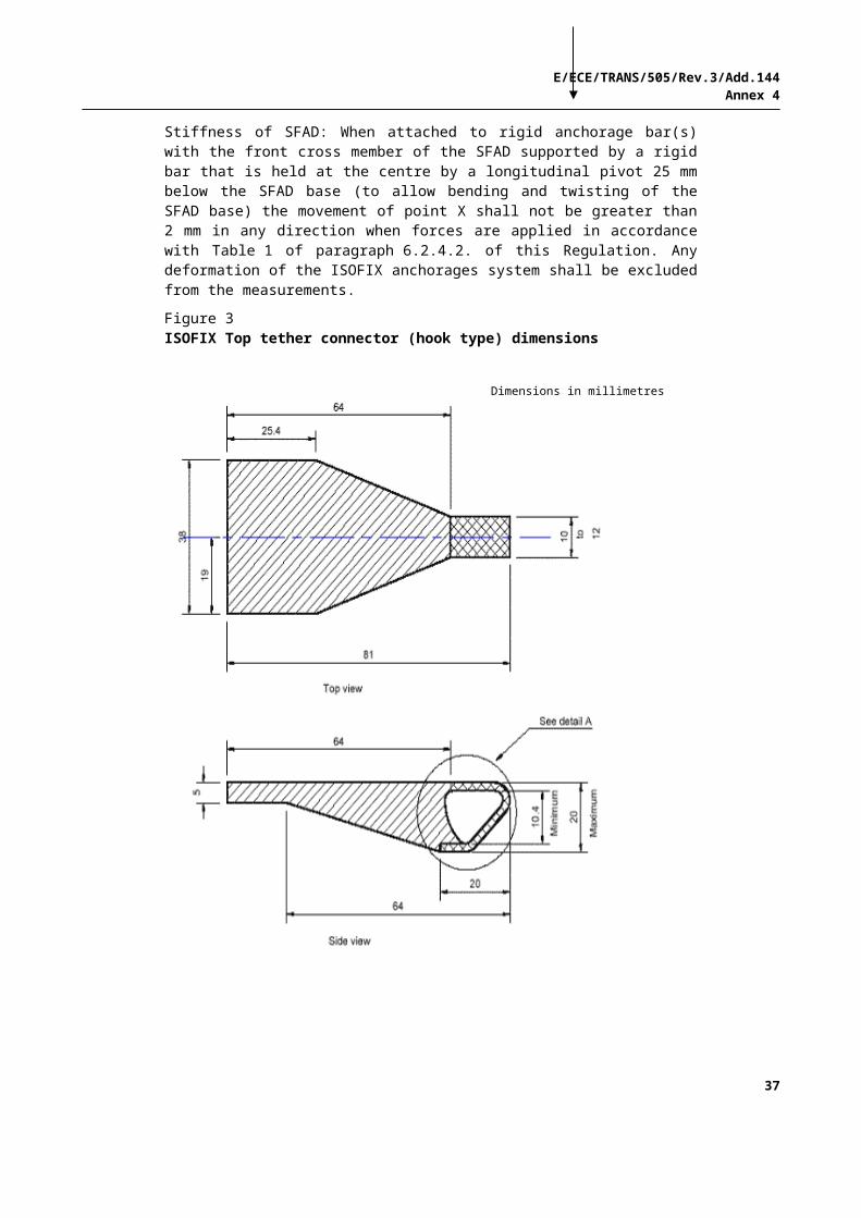
2.18. "ISOFIX top tether hook" means an ISOFIX top tether connector typically used to attach an ISOFIX top tether strap to an ISOFIX top tether anchorage as defined in Figure 3 of Annex 4 of this Regulation.
2.19. "ISOFIX top tether strap" means a webbing strap (or equivalent) which extends from the top of an ISOFIX child restraint system to the ISOFIX top tether anchorage, and which is equipped with an adjustment device, a tension-relieving device, and an ISOFIX top tether connector.
2.20. "A guidance device" is intended to help the person installing the ISOFIX child restraint system by physically guiding the ISOFIX attachments on the ISOFIX child restraint into correct alignment with the ISOFIX low anchorages to facilitate engagement.
2.21. "A child restraint fixture" means a fixture according to one of the ISOFIX size envelopes defined in paragraph 4. of Annex 17 – Appendix 2 of UN Regulation No. 16 and particularly whose dimensions are given from Figure 1 to Figure 7 in the previous mentioned paragraph 4. Those child restraint fixtures (CRF) are used in UN Regulation No. 16, to check which ISOFIX child restraint systems size envelopes can be accommodated on the vehicle ISOFIX positions. Also one of the CRF, so-called either ISO/F2 or ISO/F2X which is described in UN Regulation No. 16 (Annex 17, Appendix 2), is used in this Regulation to check the location and the possibility of access to any ISOFIX anchorages system.
2.22. "Support leg foot assessment volume" means the volume, as shown in Figures 1 and 2 of Annex 5 of this Regulation, in which the support leg foot of an i-Size child restraint system defined in UN Regulation No. 129 will rest and therefore the vehicle floor has to intersect.
2.23. "Vehicle floor contact surface" means the area which results from the intersection of the upper surface of the vehicle floor (incl. trim, carpet, foam, etc.) with the support leg foot assessment volume and is designed to withstand the support leg forces of an i-Size child restraint system defined in UN Regulation No. 129.
7

E/ECE/TRANS/505/Rev.3/Add.144
2.24. "i-Size seating position" means a seating position, if any defined by the vehicle manufacturer, which is designed to accommodate i-Size child restraint systems and fulfils the requirements defined in this Regulation.
3. Application for approval
3.1. The application for approval of a vehicle type with regard, the ISOFIX anchorages systems, the ISOFIX top tether anchorages and i-Size seating positions, if any, shall be submitted by the vehicle manufacturer or by his duly accredited representative.
3.2. It shall be accompanied by the under mentioned documents in triplicate and by the following particulars:
3.2.1. Drawings of the general vehicle structure on an appropriate scale, showing the positions of the ISOFIX anchorage systems, of ISOFIX top tether anchorages if any and in case of i-Size seating positions, the vehicle floor contact surface and detailed drawings of the ISOFIX anchorages systems if any, of the ISOFIX top tether anchorage if any, and of the points to which they are attached and in case of i-Size seating positions, the vehicle floor contact surface;
3.2.2. A specification of the materials used which may affect the strength of the ISOFIX anchorages systems and ISOFIX top tether anchorages if any and in case of i-Size seating positions, the vehicle floor contact surface;
3.2.3. A technical description of the ISOFIX anchorages systems and ISOFIX top tether anchorages if any;
3.2.4. In the case of the ISOFIX anchorages systems and of ISOFIX top tether anchorages if any affixed to the seat structure:
3.2.4.1. Detailed description of the vehicle type with regard to the design of the seats, of the seat anchorages and of their adjustment and locking systems;
3.2.4.2. Drawings, on an appropriate scale and in sufficient detail, of the seats, of their anchorage to the vehicle, and of their adjustment and locking systems.
3.3. At the option of the manufacturer, a vehicle representative of the vehicle type to be approved by the technical service conducting approval tests, or the parts of the vehicle considered essential for the ISOFIX anchorages systems, for ISOFIX top tether anchorages if any, and in case of i-Size seating positions, the vehicle floor contact surface test, shall be submitted to the technical service.
4. Approval
4.1. If the vehicle submitted for approval pursuant to this Regulation meets the relevant requirements of this Regulation, approval of that vehicle type shall be granted.
4.2. An approval number shall be assigned to each type approved. Its first two digits shall indicate the series of amendments incorporating the most recent major technical amendments made to the Regulation at the time of issue of the approval. The same Contracting Party may not assign the same number to another vehicle type as defined in paragraph 2.2. above.
8
E/ECE/TRANS/505/Rev.3/Add.144
4.3. Notice of approval or of extension or refusal or withdrawal of approval or production definitely discontinued of a vehicle type pursuant to this Regulation shall be communicated to the Parties to the 1958 Agreement which apply this Regulation by means of a form conforming to the model in Annex 1 to the Regulation.
4.4. There shall be affixed, conspicuously and in a readily accessible place specified on the approval form, to every vehicle conforming to a vehicle type approved under this Regulation an international approval mark consisting of:
4.4.1. A circle surrounding the letter "E" followed by the distinguishing number of the country which has granted approval;1
4.4.2. The number of this Regulation, to the right of the circle prescribed in paragraph 4.4.1.
4.5. If the vehicle conforms to a vehicle type approved, under one or more other Regulations Annexed to the Agreement, in the country which has granted approval under this Regulation, the symbol prescribed in paragraph 4.4.1. need not be repeated; in such a case the additional numbers and symbols of all the Regulations under which approval has been granted in the country which has granted approval under this Regulation shall be placed in vertical columns to the right of the symbol prescribed in paragraph 4.4.1.
4.6. The approval mark shall be clearly legible and be indelible.
4.7. The approval mark shall be placed close to or on the vehicle data plate affixed by the manufacturer.
4.8. Annex 2 to this Regulation gives examples of arrangements of the approval mark.
5. Specifications
5.1. Definitions
5.1.1. The H point is a reference point as defined in Annex 3 of this Regulation, which must be determined in accordance with the procedure set out in that Annex.
5.1.1.1. Point H' is a reference point corresponding to H as defined in paragraph 5.1.1. which shall be determined for every normal position in which the seat is used.
5.1.1.2. The R point is the seating reference point defined in Annex 3, Appendix 3 of this Regulation.
5.1.2. The three-dimensional reference system is defined in Appendix 2 of Annex 3 of this Regulation.
1 The distinguish numbers of the Contracting Parties to the 1958 Agreement are reproduced in Annex 3 to the Consolidated Resolution on the Construction of Vehicles (R.E.3), document ECE/TRANS/WP.29/78/Rev.6.www.unece.org/trans/main/wp29/wp29wgs/wp29gen/wp29resolutions.html
9

E/ECE/TRANS/505/Rev.3/Add.144
5.2. General specifications
5.2.1. Any ISOFIX anchorages system and any ISOFIX top tether anchorage, installed or intended to be installed, for ISOFIX child restraint systems, as well as the vehicle floor contact surface of any i-Size seating positions, shall be so designed, made and situated as to:
5.2.1.1. Any ISOFIX anchorages system and any top tether anchorage, as well as the vehicle floor contact surface of any i-Size seating positions, shall enable the vehicle, in normal use, to comply with the provisions of this Regulation.
Any ISOFIX anchorages system and ISOFIX top tether anchorage which could be added on any vehicle shall also comply with the provisions of this Regulation. Consequently, such anchorages shall be described on the application document for type approval.
5.2.1.2. ISOFIX anchorages system and ISOFIX top tether anchorage resistance are designed for any ISOFIX child restraint systems of group of mass 0; 0+; 1 as defined in UN Regulation No. 44.
5.2.1.3. An ISOFIX anchorage system, ISOFIX top tether anchorage and vehicle floor contact surface of i-Size seating positions shall be designed for i-Size child restraint system of integral class as defined in UN Regulation No. 129.
5.2.2. ISOFIX anchorage systems, design and positioning:
5.2.2.1. Any ISOFIX anchorages system shall be 6 mm 0.1 mm diameter transverse horizontal rigid bar(s) which cover(s) two zones of 25 mm minimum effective length located on the same axis as defined in Figure 4 Annex 4.
5.2.2.2. Any ISOFIX anchorages system installed on a vehicle seating position shall be located not less than 120 mm behind the design H-point as determined in Annex 4 to this Regulation, measured horizontally and up to the centre of the bar.
5.2.2.3. For any ISOFIX anchorages system installed in the vehicle, it shall be possible to attach either the ISOFIX child restraint fixture "ISO/F2" or "ISO/F2X" as defined by the vehicle manufacturer, described in UN Regulation No. 16 (Annex 17, Appendix 2).
i-Size positions shall accommodate ISOFIX child restraint fixtures "ISO/F2X", and "ISO/R2" together with the support leg installation assessment volume, as defined in UN Regulation No. 16 (Annex 17, Appendix 2). In addition, i-Size positions shall accommodate the child restraint fixture of class ISO/B2, as defined in UN Regulation No. 16 (Annex 17, Appendix 5).
5.2.2.4. The bottom surface of the ISOFIX child restraint fixture as defined by vehicle manufacturer in paragraph 5.2.2.3., shall have attitude angles within the following limits, angles measured relatively to the vehicle reference planes as defined in Annex 3 – Appendix 2 to this Regulation:
(a) Pitch: 15° 10°;
(b) Roll: 0° 5°;
(c) Yaw: 0° 10°.
For i-Size positions, providing the limits specified in paragraph 5.2.2.4. are not exceeded, it is acceptable for the shortest support-leg length, according to
10

E/ECE/TRANS/505/Rev.3/Add.144
the support-leg foot assessment volume, to result in a pitch angle greater than would otherwise be imposed by the vehicle seat or structure. It shall be possible to install the ISOFIX child restraint fixture under the increased pitch angle. This paragraph does not apply to child restraint fixtures of size ISO/B2.
5.2.2.5. ISOFIX anchorage systems shall be permanently in position or storable. In case of storable anchorages, the requirements relating to ISOFIX anchorages system shall be fulfilled in the deployed position.
5.2.2.6. Each ISOFIX low anchorage bar (when deployed for use) or each permanently installed guidance device shall be visible, without the compression of the seat cushion or seat back, when the bar or the guidance device is viewed, in a vertical longitudinal plane passing through the centre of the bar or of the guidance device, along a line making an upward angle of 30 degrees with a horizontal plane.
As an alternative to the above requirement, the vehicle shall be permanently marked adjacent to each bar or guidance device. This marking shall consist in one of the following, at the choice of the manufacturer.
5.2.2.6.1. As a minimum, the symbol of Annex 4, Figure 12 consisting of a circle with a diameter of minimum 13 mm and containing a pictogram, meeting the following conditions:
(a) The pictogram shall contrast with the background of the circle;
(b) The pictogram shall be located close to each bar of the system.
5.2.2.6.2. The word "ISOFIX" in capital letters of at least 6 mm height.
5.2.2.7. The requirements of paragraph 5.2.2.6. do not apply to the i-Size seating position. i-Size seating positions shall be marked according to paragraph 5.2.4.1.
5.2.3. ISOFIX top tether anchorages, design and positioning:
At the request of the car manufacturer, methods described in paragraphs 5.2.3.1. and 5.2.3.2. can be used alternatively.
Method described in paragraph 5.2.3.1. can only be used if the ISOFIX position is located on a vehicle seat.
5.2.3.1. Subject to paragraphs 5.2.3.3. and 5.2.3.4., the portion of each ISOFIX top tether anchorage that is designed to bind with an ISOFIX top tether connector shall be located not further than 2,000 mm far from the shoulder reference point and within the shaded zone, as shown in Figures 6 to 10 of Annex 4, of the designated seating position for which it is installed, with the reference of a template described in SAE J 826 (July 1995) and shown in Annex 4, Figure 5, according to the following conditions:
5.2.3.1.1. The "H" point of the template is located at the unique design "H" point of the full downward and full rearward position of the seat, except that the template is located laterally midway between the two ISOFIX lower anchorages;
5.2.3.1.2. The torso line of the template is at the same angle to the transverse vertical plane as the seat back in its most upright position; and
5.2.3.1.3. The template is positioned in the vertical longitudinal plane that contains the H-point of the template.
11
E/ECE/TRANS/505/Rev.3/Add.144
5.2.3.2. The ISOFIX top tether anchorage zone may be alternatively located with the aid of the Fixture "ISO/F2", as defined in UN Regulation No. 16 (Annex 17, Appendix 2, Figure 2), in an ISOFIX position equipped with ISOFIX low anchorages as shown in Figure 11 of Annex 4.
The seating position shall be the seat's rearmost, down most position with the seat back in its nominal position, or as recommended by the vehicle manufacturer.
In the side view, the ISOFIX top tether anchorage shall lie behind the "ISO/F2" fixture rear face.
The intersection between the "ISO/F2" fixture rear face and the horizontal line (Annex 4, Figure 11, reference 3) containing the last rigid point of a hardness greater than 50 Shore A at the top of the seat back defines the reference point 4 (Annex 4, Figure 11) on the centreline of the "ISO/F2" fixture. At this reference point, a maximum angle of 45° above the horizontal line defines the upper limit of the top tether anchorage zone.
In the top view, at the reference point 4 (Annex 4, Figure 11), a maximum angle of 90° extending rearward and laterally and in the rear view, a maximum angle of 40° defines 2 volumes which limit the anchorage zone for the ISOFIX top tether.
The origin of the ISOFIX top tether strap (5) is located at the intersection of the "ISO/F2" fixture with a plane 550 mm distant above the "ISO/F2" fixture horizontal face (1) on the "ISO/F2" fixture centreline (6).
Further, the ISOFIX top tether anchorage shall be more than 200 mm but not more than 2000 mm from the origin of the ISOFIX top tether strap on the rear face of the "ISO/F2" fixture, measured along the strap when it is drawn over the seat back to the ISOFIX top tether anchorage.
5.2.3.3. The portion of the ISOFIX top tether anchorage in a vehicle that is designed to bind with the ISOFIX top tether connector may be located outside the shaded zones referred to paragraphs 5.2.3.1. or 5.2.3.2. if a location within a zone is not appropriate and the vehicle is equipped with a routing device that,
5.2.3.3.1. Ensures that the ISOFIX top tether strap functions as if the portion of the anchorage designed to bind with the ISOFIX top tether anchorage were located within the shaded zone; and
5.2.3.3.2. Is at least 65 mm behind the torso line, in case of a non-rigid webbing-type routing device or a deployable routing device, or at least 100 mm behind the torso line, in the case of a fixed rigid routing device; and
5.2.3.3.3. When tested after being installed as it is intended to be used, the device is of sufficient strength to withstand, with the ISOFIX top tether anchorage the load referred to in paragraph 6.2. of this Regulation.
5.2.3.4. A tether anchorage may be recessed in the seat back, provided that it is not in the strap wrap-around area at the top of the vehicle seat back.
5.2.3.5. The ISOFIX top tether anchorage shall have dimensions to permit the attachment of an ISOFIX top tether hook as specified in Figure 3.
Clearance shall be provided around each ISOFIX top tether anchorage to allow latching and unlatching to it.
12

E/ECE/TRANS/505/Rev.3/Add.144
All anchorages located rearward of any ISOFIX anchorages system and which could be used to attach an ISOFIX top tether hook or ISOFIX top tether connector shall be designed to prevent misuse by one or more of the following measures:
(a) Designing all such anchorages in the ISOFIX top tether anchorage zone as ISOFIX top tether anchorages; or
(b) Marking only the ISOFIX top tether anchorages using one of the symbols, or its mirror image, as set out in Figure 13 of Annex 4; or
(c) Marking such anchorages not in accordance with (a) or (b) above with a clear indication that these anchorages should not be used in combination with any ISOFIX anchorages system.
For each ISOFIX top tether anchorage under a cover, the cover shall be identified by for example one of the symbols or the mirror image of one of the symbols set out in Figure 13 of Annex 4; the cover shall be removable without the use of tools.
5.2.4. i-Size seating position requirements
Each i-Size seating position, as defined by the vehicle manufacturer, shall conform to the requirements defined in paragraphs 5.2.1. to 5.2.4.3.
5.2.4.1. Markings
Each i-Size seating position shall be permanently marked adjacent to the ISOFIX low anchorages system (bar or guidance device) of the respective seating position.
The minimum marking shall be the symbol of Annex 5, Figure 4 consisting of a square with a minimum size of 13 mm and containing a pictogram and meeting the following conditions:
(a) The pictogram shall contrast with the background of the square;
(b) The pictogram shall be located close to each bar of the system.
5.2.4.2. Geometrical requirements for i-Size seating positions connected to i-Size support legs.
In addition to the requirements defined in 5.2.2. and 5.2.3. it shall be verified that the upper surface of the vehicle floor (incl. trim, carpet, foam, etc.) intersects with both of the limiting surfaces in the x- and y-directions of the support leg foot assessment volume, as shown in figures 1 and 2 of Annex 5 to this Regulation.
The support leg foot assessment volume is characterized as follows (see also Annex 5, Figures 1 and 2 of this Regulation):
(a) In width, by the two planes parallel to and 100 mm apart from the median longitudinal plane of the child restraint fixture installed in the respective seating position; and
(b) In length, by the two planes perpendicular to the plane given by the child restraint fixture bottom surface and perpendicular to the median longitudinal plane of the child restraint fixture, 585 mm and 695 mm apart from the plane passing through the centerlines of the ISOFIX lower anchorages and being perpendicular to the CRF bottom surface; and
13

E/ECE/TRANS/505/Rev.3/Add.144
(c) In height, by two planes which are parallel to and 270 mm and 525 mm below the child restraint bottom surface.
The pitch angle used for the geometrical assessment above shall be measured as in paragraph 5.2.2.4.
Compliance with this requirement may be proven by a physical test or computer simulation or representative drawings.
5.2.4.3. Vehicle floor strength requirements for i-Size seating positions.
The entire vehicle floor contact surface (see Annex 5, Figures 1 and 2) shall be of sufficient strength to withstand the loads imposed when tested in accordance with paragraph 6.2.4.5.
5.3. Minimum number of ISOFIX positions to be provided:
5.3.1. Any vehicle of category M1 shall be equipped at least with two ISOFIX positions which satisfy the requirements of this Regulation.
At least two of the ISOFIX positions shall be equipped both with an ISOFIX anchorages system and an ISOFIX top tether anchorage.
The type and number of ISOFIX fixtures, defined in UN Regulation No. 16, which can be installed on each ISOFIX position are defined in UN Regulation No. 16.
5.3.2. Notwithstanding paragraph 5.3.1. if a vehicle is only equipped with one seat row, no ISOFIX position is required.
5.3.3. Notwithstanding paragraph 5.3.1. at least one of the two ISOFIX positions systems shall be installed at the second seat row.
5.3.4. Notwithstanding paragraph 5.3.1. vehicles of category M1 need to have only one ISOFIX position system for vehicles with:
(a) Not more than two passenger doors; and
(b) A rear designated seating position for which interference with transmission and/or suspension components prevents the installation of ISOFIX anchorages according to the requirements of paragraph 5.2.2.; and
(c) Having a Power to mass ratio index (PMR) exceeding 140 according to the definitions within UN Regulation No. 51, and with the definition of the Power Mass Ratio (PMR):
PMR = (Pn / mt) * 1000 kg/kWwhere:Pn: maximum (rated) engine power expressed in kW 2
mro: mass of a vehicle in running order expressed in kgmt = mro (for vehicles of category M1)and
(d) Having an engine developing a maximum (rated) engine power greater than 200 kW.2
2 (Rated) engine power means the engine power expressed in kW (ECE) and measured by the ECE method pursuant to UN Regulation No. 85.
14

E/ECE/TRANS/505/Rev.3/Add.144
Such a vehicle needs to have only one ISOFIX anchorages system and an ISOFIX top tether anchorage at a front passenger designated seating position combined with an airbag deactivation device (if that seating position is fitted with an airbag) and a caution label indicating that there is no ISOFIX posi-tion system available at the second seat row.
5.3.5. If an ISOFIX anchorages system is installed at a front seating position protected with a frontal airbag, a de-activation device for this airbag shall be fitted.
5.3.6. Notwithstanding paragraph 5.3.1. in case of integrated "built in" child restraint system(s) the number of ISOFIX positions to be provided shall be at least two minus the number of the integrated "built in" child restraint system(s) of mass groups 0, or 0+, or 1.
5.3.7. Convertible vehicles as defined in paragraph 2.9.1.5. of the Consolidated Resolution on the Construction of Vehicles (R.E.3) with more than one seat row shall be fitted with at least two ISOFIX low anchorages. In case where an ISOFIX top tether anchorage is provided on such vehicles, it shall comply with the suitable provisions of this Regulation."
5.3.8. If a vehicle is only equipped with one seat position per row, only one ISOFIX position is required in the passenger position. In case where an ISOFIX top tether anchorage is provided on such vehicles, it shall comply with the suitable provisions of this Regulation. However where it is not possible to install even the smallest forward-facing ISOFIX fixture (as defined in UN Regulation No. 16, Appendix 2, of Annex 17) in the passenger seating position, then no ISOFIX position shall be required, provided that a child restraint system is specified for that vehicle.
5.3.9. Notwithstanding paragraph 5.3.1., ISOFIX positions are not required in ambulances or hearses as well as vehicles intended for use by the armed services, civil defence, fire services and forces responsible for maintaining public order.
5.3.10. Notwithstanding the provisions of paragraphs 5.3.1. to 5.3.4., one or more of the mandatory ISOFIX positions may be replaced by i-Size seating positions.
6. Tests
6.1. Securing the vehicle for ISOFIX anchorages tests
6.1.1. The method used to secure the vehicle during the test shall not be such as to strengthen the ISOFIX anchorages and their anchorage area or to lessen the normal deformation of the structure.
6.1.2. A securing device shall be regarded as satisfactory if it produces no effect on an area extending over the whole width of the structure and if the vehicle or the structure is blocked or fixed in front at a distance of not less than 500 mm from the anchorage to be tested and is held or fixed at the rear not less than 300 mm from that anchorage.
6.1.3. It is recommended that the structure should rest on supports arranged approximately in line with the axes of the wheels or, if that is not possible, in line with the points of attachment of the suspension.
6.1.4. If a securing method other than that prescribed in paragraphs 6.1.1. to 6.1.3. of this Regulation is used, evidence must be furnished that it is equivalent.
15
E/ECE/TRANS/505/Rev.3/Add.144
6.2. Static test requirements.
6.2.1. The strength of the ISOFIX anchorage systems shall be tested applying the forces, as prescribed in paragraph 6.2.4.3., to the static force application device (SFAD) with ISOFIX attachments well engaged.
In case of ISOFIX top tether anchorage an additional test shall be performed as prescribed in paragraph 6.2.4.4.
In case of an i-Size seating position, an additional support leg test shall be performed as described in paragraph 6.2.4.5.
All the ISOFIX positions and/or i-Size seating positions of a same seat row, which can be used simultaneously, shall be tested simultaneously.
6.2.2. The test may be carried out either on a completely finished vehicle or on sufficient parts of the vehicle so as to be representative of the strength and rigidity of the vehicle structure.
Windows and doors may be fitted or not and closed or not.
Any fitting normally provided and likely to contribute to the vehicle structure may be fitted.
The test may be restricted to the ISOFIX or i-Size position relating to only one seat or group of seats on the condition that:
(a) The ISOFIX or i-Size position concerned has the same structural characteristics as the ISOFIX or i-Size position relating to the other seats or group of seats; and
(b) Where such ISOFIX or i-Size positions are fitted totally or partially on the seat or group of seats, the structural characteristics of the seat or group of seats or floor in case of i-Size seating positions are the same as those for the other seats or groups of seats.
6.2.3. If the seats and head restraint are adjustable, they shall be tested in the position defined by the technical service within the limited range prescribed by the car manufacturer as provided in Appendix 3 of Annex 17 of UN Regulation No. 16.
6.2.4. Forces, directions and excursion limits.
6.2.4.1. A force of 135 N ± 15 N shall be applied to the centre of the lower front crossbar of the SFAD in order to adjust the fore-aft position of the SFAD rearward extension to remove any slack or tension between the SFAD and its support.
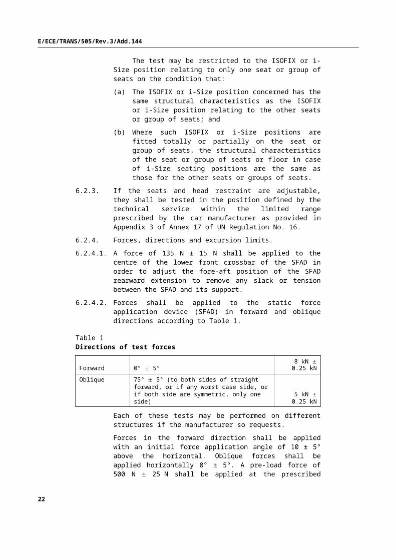
6.2.4.2. Forces shall be applied to the static force application device (SFAD) in forward and oblique directions according to Table 1.
Table 1Directions of test forces
Forward 0° 5°8 kN 0.25
kN
Oblique 75° 5° (to both sides of straight forward, or if any worst case side, or if both side are symmetric, only one side)
5 kN 0.25 kN
Each of these tests may be performed on different structures if the manufacturer so requests.
16

E/ECE/TRANS/505/Rev.3/Add.144
Forces in the forward direction shall be applied with an initial force application angle of 10 ± 5° above the horizontal. Oblique forces shall be applied horizontally 0° ± 5°. A pre-load force of 500 N ± 25 N shall be applied at the prescribed loading point X indicated in Figure 2 of Annex 4. Full application of the load shall be achieved as rapidly as possible, and within a maximum load application time of 30 seconds. However, the manufacturer may request the application of the load to be achieved within 2 seconds. The force shall be maintained for a minimum period of 0.2 s.
All measurements shall be made according to ISO 6487 with CFC of 60 Hz or any equivalent method.
6.2.4.3. Tests of ISOFIX anchorages system only:
6.2.4.3.1. Forward direction force test:
Horizontal longitudinal excursion (after pre-load) of point X of SFAD during application of the 8 kN ± 0.25 kN force shall be limited to 125 mm and permanent deformation including partial rupture or breakage of any ISOFIX low anchorage or surrounding area shall not constitute failure if the required force is sustained for the specified time.
6.2.4.3.2. Oblique direction force test:
Excursion in the direction of the force (after pre-load) of point X of SFAD during application of the 5 kN 0.25 kN force shall be limited to 125 mm and permanent deformation including partial rupture or breakage of any ISOFIX low anchorage or surrounding area shall not constitute failure if the required force is sustained for the specified time.
6.2.4.4. Test of ISOFIX anchorages systems and ISOFIX top tether anchorage:
A tension pre-load of 50 N ± 5 N must be applied between the SFAD and the top-tether anchorage. Horizontal excursion (after pre-load) of point X during application of the 8 kN ± 0.25 kN force shall be limited to 125 mm and permanent deformation including partial rupture or breakage of any ISOFIX low anchorage and top tether anchorage, or surrounding area shall not constitute failure if the required force is sustained for the specified time.
6.2.4.5. Test for i-Size seating positions:
In addition to the tests specified in paragraphs 6.2.4.3. and 6.2.4.4., a test with a modified static force application device, which consists of a SFAD and includes a support leg test probe as defined in Figure 3 of Annex 5, shall be performed. The support leg test device shall be adjusted in length and width to assess the vehicle floor contact surface, as defined in paragraph 5.2.4.2. (see also Figures 1 and 2 of Annex 5 to this Regulation). The height of the support leg test device shall be adjusted in a way that the foot of the support leg test device is in contact with the upper surface of the vehicle floor. In case of incremental height adjustment, the first notch where the foot rests stable on the floor shall be chosen; in case of a non-incremental/continuous adjustment of the support leg test device height, the pitch angle of the SFAD shall be increased by 1.5 +/- 0.5 degrees due to the height adjustment of the support leg test device.
The horizontal excursion (after pre-load) of point X of the SFAD during application of the 8 kN ± 0.25 kN force shall be limited to 125 mm and permanent deformation including partial rupture or breakage of any ISOFIX
17
E/ECE/TRANS/505/Rev.3/Add.144
low anchorage and the vehicle floor contact surface, or surrounding area shall not constitute failure if the required force is sustained for the specified time.
Table 2Excursions limits
Force direction Maximum excursion of point X of SFAD
Forward 125 mm longitudinal
Oblique 125 mm force direction
6.2.5. Additional forces
6.2.5.1. Seat inertia forces.
For the installation position where the load is transferred into a vehicle seat assembly, and not directly into the vehicle structure, a test shall be carried out to ensure that the strength of the vehicle seat anchorages to the vehicle structure is sufficient. In this test, a force equal to 20 times the mass of the relevant parts of the seat assembly shall be applied horizontally and longitudinally in a forward direction to the seat or the relevant part of the seat assembly corresponding to the physical effect of the mass of the seat in question to the seat anchorages. The determination of the additional applied load or loads and the load distribution shall be made by the manufacturer and agreed by the Technical Service.
At the request of the manufacturer, the additional load can be applied at the X point of SFAD during the static tests described above.
If the top tether anchorage is integrated to the vehicle seat, this test shall be performed with the ISOFIX top tether strap.
No breakage shall occur and excursion requirements given in the Table 2 have to be fulfilled.
Note: This test does not have to be performed in case of any anchorage of the vehicle safety-belt system is integrated to the vehicle seat structure, and the vehicle seat is already tested and approved to meet the anchorage load tests required by this Regulation for adult passenger restraint.
7. Modifications and extension of approval of the vehicle type
7.1. Every modification of the vehicle type shall be notified to the Type Approval Authority which approved the vehicle type. The Authority may then either:
7.1.1. Consider that the modifications made are unlikely to have an appreciable adverse effect and that in any case the vehicle still complies with the requirements; or
7.1.2. Require a further test report from the technical service responsible for conducting the tests.
7.2. Confirmation or refusal of approval, specifying the alterations, shall be communicated by the procedure specified in paragraph 4.3. above to the Parties to the Agreement which apply this Regulation.
18

E/ECE/TRANS/505/Rev.3/Add.144
7.3. The competent authority issuing the extension of approval shall assign a series number for such an extension and inform thereof the other Parties to the 1958 Agreement applying this Regulation by means of a communication form conforming to the model in Annex 1 to this Regulation.
8. Conformity of production
The conformity of production procedures shall comply with those set out in the Agreement, Schedule 1 (E/ECE/TRANS/505/Rev.3), with the following requirements:
8.1. Every vehicle bearing an approval mark as prescribed under this Regulation shall conform to the vehicle type approved with regard to details affecting the characteristics of the ISOFIX anchorages system and ISOFIX top tether anchorage.
8.2. In order to verify conformity as prescribed in paragraph 8.1. above, a sufficient number of serially-produced vehicles bearing the approval mark required by this Regulation shall be subjected to random checks.
8.3. As a general rule the checks as aforesaid shall be confined to the taking of measurements. However, if necessary, the vehicles shall be subjected to some of the tests described in paragraph 6. above, selected by the technical service conducting approval tests.
9. Penalties for non-conformity of production
9.1. The approval granted in respect of a vehicle type pursuant to this Regulation may be withdrawn if the requirement laid down in paragraph 8.1. above is not complied with or if its ISOFIX anchorages system and ISOFIX top tether anchorage failed to pass the checks prescribed in paragraph 8. above.
9.2. If a Contracting Party to the Agreement which applies this Regulation withdraws an approval it has previously granted, it shall forthwith so notify the other Contracting Parties applying this Regulation, by means of a communication form conforming to the model in Annex 1 to this Regulation.
10. Production definitively discontinued
If the holder of the approval completely ceases to manufacture a type of ISOFIX anchorages system and ISOFIX top tether anchorage approved in accordance with this Regulation, he shall so inform the authority which granted the approval. Upon receiving the relevant communication that authority shall inform thereof the other Contracting Parties to the 1958 Agreement, which apply this Regulation by means of a communication form conforming to the model in Annex 1 to this Regulation.
19

E/ECE/TRANS/505/Rev.3/Add.144
11. Names and addresses of Technical Services responsible for conducting approval tests and of
Type Approval Authorities
The Contracting Parties to the 1958 Agreement applying this Regulation shall communicate to the United Nations secretariat the names and addresses of the Technical Services responsible for conducting approval tests and of the Type Approval Authorities which grant approval and to which forms certifying approval or extension, or refusal or extension or withdrawal of approval, issued in other countries, are to be sent.
20

E/ECE/TRANS/505/Rev.3/Add.144Annex 1
Annex 1
Communication
(Maximum format: A4 (210 x 297 mm))
1
Concerning:2 Approval granted
Approval extendedApproval refusedApproval withdrawnProduction definitively discontinued
of a vehicle type with regard to ISOFIX anchorages systems, and ISOFIX top tether anchorages and i-Size seating positions if any pursuant to UN Regulation No. 145
Approval No..................................................... Extension No.........................................
1. Trade name or mark of the power-driven vehicle.............................................................................................................................................................................................................
2. Type of vehicle .................................................................................................................................................................................................................................................................
3. Manufacturer's name and address ....................................................................................................................................................................................................................................
4. If applicable, name and address of manufacturer's representative ...................................................................................................................................................................................
........................................................................................................................................
1 1 Distinguishing number of the country which has granted/extended/refused/withdrawn approval (see approval provisions in the Regulation).
2 Strike out what does not apply.
21
issued by: Name of Administration:..................................................................................................................1
E/ECE/TRANS/505/Rev.3/Add.144Annex 1
5. Description of seats2
Utilises additional force according to paragraph 6.2.5.1. of this UN Regulation: Yes/No2
Supplemented force: ....................................................................................................Utilises the exemption per note to paragraph 6.2.5.1. based on safety belt anchorage tests per
UN Regulation No. 14 paragraph 6.4.4.: Yes/No2 UN Regulation No. 14 Approval No.............................................................................
6. Utilises ISOFIX exemption permitted by paragraph 5.3.8.: Yes/No2.......................................
7. Vehicle submitted for approval on: ..........................................................................................
8. Technical Service responsible for conducting approval tests: .................................................
........................................................................................................................................
9. Date of report issued by that Service: ...........................................................................
10. Number of report issued by that Service: .....................................................................
11. Approval granted/extended/refused/withdrawn2
12. Position of approval mark on vehicle: ..........................................................................
13. Place: .............................................................................................................................
14. Date: ..............................................................................................................................
15. Signature: ......................................................................................................................
16. The following documents, filed with the Type Approval Authority which has granted approval and available on request are annexed to this communication:
Drawings, diagrams and plans of the ISOFIX anchorages systems, of the top tether anchorages if any, vehicle floor contact surface ofi-Size seating positions if any, and of the vehicle structure;
Photographs of the ISOFIX anchorages systems, of the top tether if any, vehicle floor contact surface of i-Size seating positions if any, and of the vehicle structure;
Drawings, diagrams and plans of the seats, of their anchorage on the vehicle;
Photographs of the seats, of their anchorage.
22

E/ECE/324/Rev.3/Add.144E/ECE/TRANS/505/Rev.3/Add.144
Annex 3
Annex 2
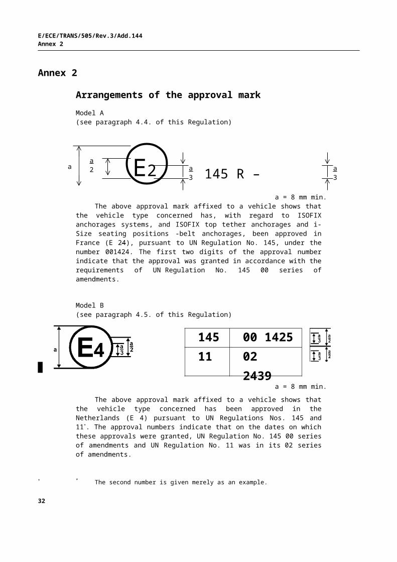
Arrangements of the approval mark
Model A(see paragraph 4.4. of this Regulation)
a = 8 mm min.The above approval mark affixed to a vehicle shows that the vehicle type concerned
has, with regard to ISOFIX anchorages systems, and ISOFIX top tether anchorages and i-Size seating positions -belt anchorages, been approved in France (E 24), pursuant to UN Regulation No. 145, under the number 001424. The first two digits of the approval number indicate that the approval was granted in accordance with the requirements of UN Regulation No. 145 00 series of amendments.
Model B(see paragraph 4.5. of this Regulation)
a = 8 mm min.
The above approval mark affixed to a vehicle shows that the vehicle type concerned has been approved in the Netherlands (E 4) pursuant to UN Regulations Nos. 145 and 11 *. The approval numbers indicate that on the dates on which these approvals were granted, UN Regulation No. 145 00 series of amendments and UN Regulation No. 11 was in its 02 series of amendments.
* * The second number is given merely as an example.
23
E2a a3
a3
a2 145 R – 001424
145 00 142511 02 2439

ECE/TRANS/WP.29/2017/133Annex 3
Annex 3
Procedure for determining the "H" point and the actual torso angle for seating positions in motor vehicles2
Appendix 1 - Description of the three dimensional "H" point machine (3-D H machine)1
Appendix 2 - Three-dimensional reference system1
Appendix 3 - Reference data concerning seating positions1
2 The procedure is described in Annex 1 and its Appendices 1, 2 and 3 to the Consolidated Resolution on the Construction of Vehicles (R.E.3) (document ECE/TRANS/WP.29/78/Rev.6 - www.unece.org/trans/main/wp29/wp29wgs/wp29gen/wp29resolutions.html
24

E/ECE/TRANS/505/Rev.3/Add.144Annex 4
Annex 4
ISOFIX anchorages systems and ISOFIX top tether anchorages
Figure 1
Static Force Application Device (SFAD), isometric views
25

E/ECE/TRANS/505/Rev.3/Add.144Annex 4
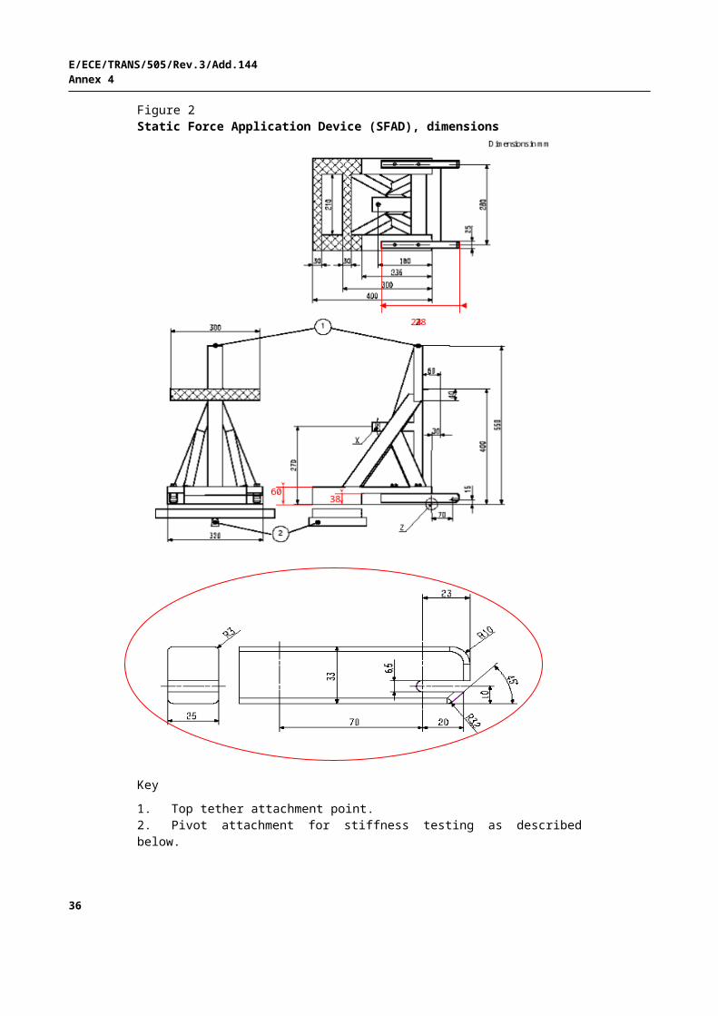
Figure 2Static Force Application Device (SFAD), dimensions
Key
1. Top tether attachment point.2. Pivot attachment for stiffness testing as described below.
Stiffness of SFAD: When attached to rigid anchorage bar(s) with the front cross member of the SFAD supported by a rigid bar that is held at the centre by a longitudinal pivot 25 mm below the SFAD base (to allow bending and twisting of the SFAD base) the movement of
26

E/ECE/TRANS/505/Rev.3/Add.144Annex 4
point X shall not be greater than 2 mm in any direction when forces are applied in accordance with Table 1 of paragraph 6.2.4.2. of this Regulation. Any deformation of the ISOFIX anchorages system shall be excluded from the measurements.
Figure 3ISOFIX Top tether connector (hook type) dimensions
27
Dimensions in millimetres

E/ECE/TRANS/505/Rev.3/Add.144Annex 4
Figure 4Distance between both low anchorage zones
Figure 5Two dimensions template
28
25 mm25 mm
255 mm maximum
305 mm minimum

E/ECE/TRANS/505/Rev.3/Add.144Annex 4
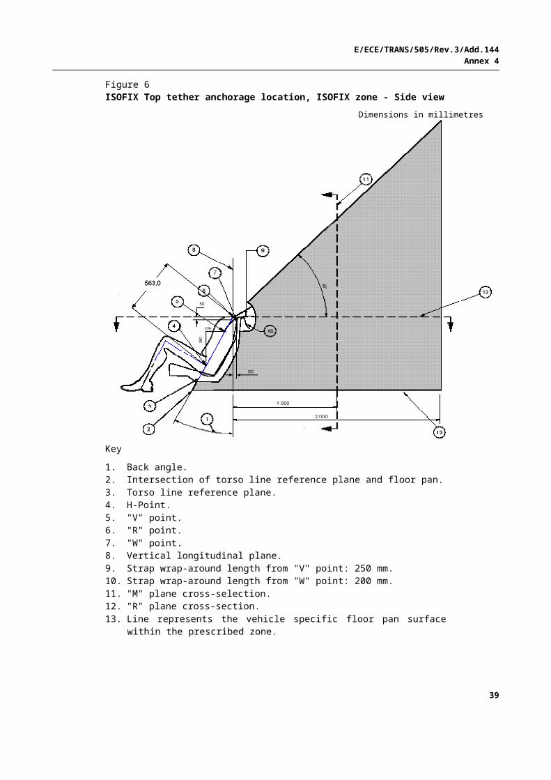
Figure 6ISOFIX Top tether anchorage location, ISOFIX zone - Side view
Dimensions in millimetres
Key
1. Back angle.2. Intersection of torso line reference plane and floor pan.3. Torso line reference plane.4. H-Point.5. "V" point.6. "R" point.7. "W" point.8. Vertical longitudinal plane.9. Strap wrap-around length from "V" point: 250 mm.10. Strap wrap-around length from "W" point: 200 mm.11. "M" plane cross-selection.12. "R" plane cross-section.13. Line represents the vehicle specific floor pan surface within the prescribed zone.
29

E/ECE/TRANS/505/Rev.3/Add.144Annex 4
Notes:1. Portion of top tether anchorage that is designed to bind with the top tether hook to be
located within shaded zone.2. "R" Point: Shoulder reference point.3. "V" Point: V-reference point, 350 mm vertically above and 175 mm horizontally back
from H-point.4. "W" Point W-reference point, 50 mm vertically below and 50 mm horizontally back
from "R" point.5. "M" Plane: M-reference plane, 1,000 mm horizontally back from "R" point.6. The forward most surfaces of the zone are generated by sweeping the two
wraparound lines throughout their extended range in the front part of the zone. The wraparound lines represent the minimum adjusted length of typical top tether straps extending from either the top of the CRS (W-point), or lower on the back of the CRS (V-Point).
Figure 7ISOFIX Top tether anchorage location, ISOFIX zone - Enlarged side view of wrap-around area
Dimensions in millimetres
Key1. "V" point.2. "R" point.3. "W" point.4. Strap wrap-around length from "V" point: 250 mm.5. Vertical longitudinal plane.6. Strap wrap-around length from "W" point: 200 mm.7. Arcs created by wrap-around lengths.8. H-point.
30

E/ECE/TRANS/505/Rev.3/Add.144Annex 4
Notes:1. Portion of top tether anchorage that is designed to bind with the top tether hook to be
located within shaded zone.2. "R" point: Shoulder reference point.3. "V" point: V-reference point, 350 mm vertically above and 175 mm horizontally
back from H-point.4. "W" point: W-reference point, 50 mm vertically below and 50 mm horizontally back
from "R" point.5. "M" plane: M-reference plane, 1,000 mm horizontally back from "R" point.6. The forward most surface of the zone are generated by sweeping the two
wraparound lines throughout their extended range in the front part of the zone. The wraparound lines represent the minimum adjusted length of typical top tether straps extending from either the top of the CRS (W-point), or lower on the back of the CRS (V.point).
Figure 8ISOFIX Top tether anchorage location, ISOFIX zone - Plan view
(R-plane cross section)
31
Dimensions in millimetres
1
3
2
4
5
E/ECE/TRANS/505/Rev.3/Add.144Annex 4
Key
1. Median plane.2. "V" point.3. "R" point.4. "W" point.5. Vertical longitudinal plane.
Notes:1. Portion of top tether anchorage that is designed to bind with the top tether hook to be located
within shaded zone.2. "R" point: Shoulder reference point.3. "V" point: V-reference point, 350 mm vertically above and 175 mm horizontally back from H-
point.4. "W" point: W-reference point, 50 mm vertically below and 50 mm horizontally back from "R"
point.
Figure 9ISOFIX Top tether anchorage location, ISOFIX zone - Front view
32

E/ECE/TRANS/505/Rev.3/Add.144Annex 4
Key 1. "V" point.2. "W" point.3. "R" point.4. Median plane.5. Area view along torso reference plane.
Notes:1. Portion of top tether anchorage that is designed to bind with the top tether hook to be
located within shaded zone.2. "R" point: Shoulder reference point.3. "V" point: V-reference point, 350 mm vertically above and 175 mm horizontally
back from H-point.4. "W" point: W-reference point, 50 mm vertically below and 50 mm horizontally back
from "R" point.
Figure 10ISOFIX Top tether anchorage location, ISOFIX zone - Three-dimensional schematic view
Key 1. "H" point. 4. "R" point. 7 Floor pan surface.2. "V" point. 5. 45° plane. 8 Front edge of zone.
33
E/ECE/TRANS/505/Rev.3/Add.144Annex 4
3. "W" point. 6. "R" plane cross-section.Notes:1. Portion of top tether anchorage that is designed to bind with the top tether hook to be
located within shaded zone.2. "R" point: Shoulder reference point.
Figure 11Alternative method of locating the top tether anchorage using the "ISO/F2" (B) fixture, ISOFIX zone - side, top and rear views
Dimensions in millimetres
1. "ISO/F2" (B) fixture horizontal face. 4. Intersection between 2 and 3.2. "ISO/F2" (B) fixture rear face. 5. Tether reference point.3. Horizontal line tangent to top. 6. "ISO/F2" (B) fixture centreline.
of seat back (last rigid point of a 7. Top tether strap.hardness greater than 50 Shore A). 8. Limits of anchorage zone.
Figure 12ISOFIX low anchorage symbol
Notes:1. Drawing not to scale.2. Symbol may be shown in mirror image.3. Colour of the symbol at choice of manufacturer.
34
E/ECE/TRANS/505/Rev.3/Add.144Annex 4
Figure 13Symbol used to identify the location of a top tether anchorage that is under a cover
Notes:1. Dimensions in mm. 2. Drawing not to scale. 3. The symbol shall be clearly visible either by means of contrast colours or by
adequate relief if it is moulded or embossed.
35
E/ECE/TRANS/505/Rev.3/Add.144Annex 5
Annex 5
i-Size seating position
Figure 1 3D view of the support leg foot assessment volume
Key:
1. Child Restraint Fixture (CRF).2. ISOFIX low anchorages bar.3. Median longitudinal plane of the CRF.4. Support leg foot assessment volume.5. Vehicle floor contact surface.
Dimensions in mm.Note: Drawing not to scale.
E/ECE/TRANS/505/Rev.3/Add.144Annex 5
Figure 2Side view of the support leg foot assessment volume
Key:
1. Child Restraint Fixture (CRF).2. ISOFIX low anchorages bar.3. Plane formed by the bottom surface of the CRF when installed in the designated
seating position.4. Plane passing through the lower anchorage bar and oriented perpendicular to the
median longitudinal plane of the CRF and perpendicular to the plane formed by the bottom surface of the CRF when installed in the designated seating position.
5. Support leg foot assessment volume within which the vehicle floor has to be located. This volume represents the length and height adjustment range of an i-Size child restraint system support leg.
6. Vehicle floor.
Dimensions in mm.Note: Drawing not to scale.
37

E/ECE/TRANS/505/Rev.3/Add.144Annex 5
Figure 3Example for a modified Static force application device with support leg test probe (SFADSL) showing the required adjustment range and dimensions of the support leg foot
Key:
1. Support leg test device.2. Support leg foot.3. SFAD (as defined in annex 4 of this Regulation).
Notes:
1. Drawing not to scale.
2. The support leg test device shall:
(a) Ensure testing within the entire vehicle floor contact surface defined for individual i-Size seating positions;
(b) Be rigidly fixed to the SFAD so that the forces applied to the SFAD will directly induce test forces into the vehicle floor, without reduction of the reactive test forces due to damping within or deformation of the support leg test device itself.
3. The support leg foot shall consist of a cylinder, having a width of 80 mm, a diameter of 30 mm and on both side faces rounded edges with a 2.5mm radius.
4. In case of incremental height adjustment, the distance between the steps for adjustment shall not be more than 20 mm.
Dimensions in mm.
38
E/ECE/TRANS/505/Rev.3/Add.144Annex 5
Figure 4Symbol used to identify an i-Size seating position
Notes:
1. Drawing not to scale.2. Colour of the symbol is the manufacturer's choice.
39