· tripping device. automati cally ... fixed ratio current sensors are available up to the ... 4...
TRANSCRIPT

U2. �� - ----- - - - - ---- �-�-- �-� --- " - --·-
� ,_ _ - ---� �' - �- - -----
,, - · - - - . --.. - -� - ,.,___
www . El
ectric
alPar
tMan
uals
. com

Micro-VersaTrip" Solid-State Protection Programmers
9 Function Programmer
2
4 Function Programmer 0
www . El
ectric
alPar
tMan
uals
. com

Table of Contents
REECEIVED MAR 31198.3 s.w.a.a. co.
Introdu cti on . . . . . . . . . . . . . . . . . . . . . . . . . . . . . . . . . . . . . . . . . . . . . . . . . . . . . . . . . . . . . . . . . . . . . . . . . 4-5
Mic ro-Ve rsaTrip Breaker System . . . . . . . . . . . . . . . . . . . . . . . . . . . . . . . . . . . . . . . . . . . . . . . . . . . . . . . 6-7
Mi cro-Ve rsaTrip Programmer . . . . . . . . . . . . . . . . . . . . . . . . . . . . . . . . . . . . . . . . . . . . . . . . . . . . . . . . . . 8-9
Programmer Characterist i cs-4 Functi on . . . . . . . . . . . . . . . . . . . . . . . . . . . . . . . . . . . . . . . . . 10-12, 19
-9 Function . . . . . . . . . . . . . . . . . . . . . . . . . . . . . . . . . . . . . . . . . . . 13-18
T i m e C u r rent C u rves . . . . . . . . . . . . . . . . . . . . . . . . . . . . . . . . . . . . . . . . . . . . . . . . . . . . . . . . . . . . . . . 20-22
Interrupting Capacit ies . . . . . . . . . . . . . . . . . . . . . . . . . . . . . . . . . . . . . . . . . . . . . . . . . .. . . . . . . . . . . . . 23
Ordering Info rmation-Example ....................................................... 24
-Breake r Cat. Nos . . . . . . . . . . . . . . . . . . . . . . . . . . . . . . . . . . . . . . . . . . . . . 25-27
-Internal Accessories . . . . . . . . . . . . . . . . . . . . . . . . . . . . . . . . . . . . . . . . . 27-29
-External Accesso ries . . . . . . . . . . . . . . . . . . . . . . . . . . . . . . . . . . . . . . . . . 30-32
-Mo unting Means . . . . . . . . . . . . . . . . . . . . . . . . . . . . . . . . . . . . . . . . . . . . . . . 33
-Drawout Assembly .............................................. 34
-Enclosu res . . . . . . . . . . . . . . . . . . . . . . . . . . . . . . . . . . . . . . . . . . . . . . . . . . . . . 35
Outl ine Drawings . . . . . . . . . . . . . . . . . . . . . . . . . . . . . . . . . . . . . . . . . . . . . . . . . . . . . . . . . . . . . . . . . . 36-38
G u i de Form Specif i cati ons . . . . . . . . . . . . . . . . . . . . . . . . . . . . . . . . . . . . . . . . . . . . . . . . . . . . . . . . . . . . 39
3 www . El
ectric
alPar
tMan
uals
. com

Micro-VersaTrip" ... Reliability, Flexibility, Accuracy, Quality ... in One Protection Package
4
Micro-VersaTrip® is a miniaturized, standardized, state-of-the-art program m er, incorporating technological advancem ents in overcurrent protection. It is the latest in a series of protection packages d esigned and manufactured by the General Electric Company to provide reliable, flexible protection system s.
Expanded functions, with increased versatility and coordination are contained in the Micro-VersaTrip program mer which in m any cases requires no external relaying power s upply or accessories.
4 Function Micro-VersaTrip® Circuit Breakers
J·FRAME K·FRAME
www . El
ectric
alPar
tMan
uals
. com

Today's soph isticated d istribution systems requ ire increased accu racy, rel iability and versati l ity. MicroVersaTr i p with its new generation sol id state circu itry offers:
• Integral ground fault protection with memory.
• Increased selectivity with both ramp functions and zone-selective interlocking on short time and ground fault.
• Improved system coordi-
nation with accu rate 8-point trip adjustment switches and m u lt iple time-delay bands.
• Enhanced s ignal ing capab il ities with long-t ime timing l ight and local and remote popout fault ind ication targets.
• Ful l function MicroVersaTrip test set provides field testing capabi l ities for programmer electronics, flux sh ifter and current sensors.
• Maximum flex ib il ity with
combinations of long time, short t ime, instantaneous, ground fault, s ignal ing and system inte rlocking functions.
• Increased accu racy and rel iabil ity through the use of h igh g rade components, gold-plated switches and a protective conformal epoxy coating on the electronics.
T hese new d imensions in electron ics offer the add it ional benefits of a s ing le programmer concept
9 Function Micro-VersaTrip® Circuit Breakers
J-FRAME K-FRAME
(Micro-VersaTr ip replaces previous Versatrip� Selectrip;M ECS and S S T™ sol id state devices) , s imil ar prog rammer options among d ifferent b reaker l ines, a s ingle test set and only three t ime current cu rves to cover the full GE l ine of molded-case circuit breakers, POWER BREAK insulated case circu it breakers and AKR low voltage power circuit breakers.
5 www . El
ectric
alPar
tMan
uals
. com

The Micro-VersaTrip� System: Programmer, Flux Shifter, Current Sensors
The M icro-VersaTr ip system for molded case circuit breakers consists of three parts; a p lug- in protection programmer, a flux sh ift trip device, and current sensor package.
Protection
Programmer
Current sensor-powered sol id-state logic un it. I ncorporates rotary adjustment knobs for up to n ine func-
4 Function Micro-VersaTrip® System
Flux-Shifter
6
Current Sensor Package
tions as wel l as targets for mechanical fault tr i p ind ications. (MicroVersaTrip 9). U p to fou r adjustments with M i croVersaTrip 4.
Programmer
www . El
ectric
alPar
tMan
uals
. com

Flux-shift Trip
Device
Low energy positive action tr ipping device. Automatically powered and contro l led by the protection programmer.
Current Sensor
Package
Three phase cu rrent sensors incorporated i nto a s ingle package provid i ng maximum flexi b i l ity and rel iabi l ity.
These rel iable components, coupled with the p roven dependabi l ity of General E lectr ic Molded Case c i rcuit breakers, combine to p rovide the most flex ib le and rel iable sol id state protection system avai l ab le.
9 Function Micro-VersaTrip® System
Flux-Shifter Current Sensor Package
Programmer
7 www . El
ectric
alPar
tMan
uals
. com

8
The Micro-VersaTrip® Programmer ... Electronic Precision for Breaker Reliability and Stability
Programmable MicroElectronic Processor
The programmable microelectronic processor forms the basis of the MicroVersaTri p protection prog rammer. Thi s m i n i atu rizat ion of c i rcuitry provides the i ncreased flexib i l ity requ i red to i ncorporate up to n ine adjustable time-current functions, three mechanica l
fau l t i ndicators ( local and remote) , a long-time pickup LED ind icator ( local and remote) and zone selective inter locki ng. Al l adjustable programmer functions are automatic and selfcontained. This compi lation of functions provides the basis for the most flexib le and u sefu l b reaker design presently avai lable.
Specially Treated Printed Circuit Cards
Each printed c i rcuit card is g iven a protective conformal epoxy coat ing to prevent moistu re absorption , fungus g rowth and signal leakage. All electronics are housed with in a meta l l ic or molded enclosure designed to protect against .hi-fault i nterruption arcs, magnetic
4 Function Micro-VersaTrip® Programmer
Epoxy Glass Printed Circuit -.... Board
8 Position Adjustment Switches
Gold Plated Rotary Switches
i nterference, d ust and other contaminants.
Gold-Plated Rotary Switch Adjustments
Gold-plated rotary switch adjustments provide h ighly rel iable fixed point f ie ld prog rammable controls for g reater repetitive accuracy and more precise MicroVersaTrip tr ip u ni t sett ings.
Conformal Epoxy Protective Coating
,.
www . El
ectric
alPar
tMan
uals
. com

Gold-plated surfaces on al l electrical connectors and adjustments provide longlasting and positive electrical contact.
Integral Circuitry
Integ ral circu itry is designed to reduce system down time by analyzi ng any overcurrent fault and visual ly identifyi ng its cause as an overload,
short circuit or g round fault. Both local and remote ind ication is avai lable. A longtime pickup t iming ind icator is also p rovided as an aid in testing and identify ing an overcurrent condition in process.
9 Function Micro-VersaTrip® Programmer
Epoxy Glass Printed Circuit Board
Conformal Epoxy Protective Coating
/
Gold Rotary Switches
8 Position Adjustment Switches
Fault Indication Module
Zone Selective Interlocking Module
9 www . El
ectric
alPar
tMan
uals
. com

Micro-VersaTrip® 4
Programmer
4 Function Micro-VersaTrip®Circuit Breaker
10
. 9X
1 .0X
. 8X
CURRENT
SETTING(C)
8 Position Discrete Point Switches
Wide Range of Ampere Adjustment is provided in two levels:
1 . The programmer cu rrent sett i ng is suppl ied with a 50-1 00 percent adjustment range-standard . The programmer long-t ime pickup is factory set at 1 . 1 ti mes the cu rrent sett i ng.
2. Fixed rat io current sensors are avai lable up to the maxi m u m frame rat ing of the breaker-standard .
www . El
ectric
alPar
tMan
uals
. com

Micro-VersaTrip' 4
Programmer Characteristics
Table 11.1-Micro-VersaTrip® 4 Programmer Selection
St and ard Programmer Functions P ro grammer
• Adj ustable Cu rrel'lt Sett ing (C) X
Fixed Long-Ti me Pickup ( 1 .1 C) X Long Time
Fixed Long-Time Delay X
Long-Time T iming L ight X
Short Time • Adj Short-Time Pickup
Short-Ti me Delay J2t ram p
lnstanta- • Adj Instantaneous Pickup X
neous • Fixed I nstantaneous Pickup
• Adj G round Fault P ickup 1'1
G rou nd -Zero Sequence
Fault -G round Retu rn
• Adj G round Fault Delay
111 For 1 PH, 2W-1 PH, 3W-3PH, 3W-3PH, 4W systems. O rder neutral
transformer by catalog number when neutral is present.
O pt io nal F unct io ns Add to St and ard P ro grammer
N G GR NG NGR
X X X X X
X X X X X
X X X X X
X X X X X
X X X
X X X
X X
X X X
X X
X X
X X X X
Table 11.2-Micro-VersaTrip®4 Programmer Characteristics
(X) F ix ed
M ax imum Sensors F rame Siz e
Rat ing Sensor (A mps) Curr ent
Rat ings (Amps)
J400 400 1 50, 200, 300, 400
1 50, 200, J600 600 300, 400,
500, 600
K800 800 400 , 600,
800
400 , 600, K1 200 1 200 800, 1 000,
1 200
C urr ent Sett ing
(Mult ipl e o f Sensor C urr ent Rat ing)
(X)
.5 , .6, .7, .8, .85, .9,
.95, 1 .0 (X)
"
"
"
Lo ng- Time
P ickup (Mult ipl e of Curr ent Sett ing)
(C)
Fixed at 1.1 C
"
"
"
D el ay 111 (Seco nds)
1 2 .5
"
"
"
111 Time delay shown at ,600% of cu rrent setting at lower l i m it of each band. "1 Time delay shown at lower l i mit of each ban d .
Al l pickup tolerances are± 1 0%. G round Fault pickup not to exceed 1 200 amperes.
Sho rt -Time Ad just able
P ick up (Mult ip le o f C ur rent Sett ing)
(C)
1 .5, 2, 2 .5, 3, 4, 5, 7,
9 (C)
"
"
"
I nst ant aneo us l't P icku p
D el ay"' (M ult ipl e o f Ramp Senso r C urr ent
(Seco nds) Rat ing) (X)
1 .5, 2, 2.5, 0.4 3, 4, 6, 8
1 0 (X)
" "
" "
" "
X� Sensor Cu rrent Rating C � Cu rrent Sett i n g
Grou nd F ault
P ickup (Mult ip l e o f
Senso r C urrent Rat ing)
(X)
.2, .25, .3, .35, .4, .45,
.5, .6 (X)
"
"
"
D elay 12> (Seco nds)
0.1 0, 0.22, 0.36
"
"
"
1 1 www . El
ectric
alPar
tMan
uals
. com

Micro-VersaTrip� 4
Programmer Functions
Current Setting (Standard) The adjustable current sett ing varies the level of current the breaker wi l l carry indefin itely without tripping. Adjustable in 8 steps from 50-1 00% of sensor cu'rrent rating, changing this sett ing has the same effect as chang ing the trip u nit i n an interchangeable tr ip c ircuit breaker.
Short-Time Pickup (Optional) The short-t ime pickup adjustment contro ls the level of high cu rrent the breaker can carry for short periods of t ime without tri pp ing . Permits downstream breakers to clear shortci rcuit fau lts without tripping out the up-stream protective device. Avai lable as an option with the " N" suffix. (F ixed instantaneous suppl ied with "N" suffix.)
Adjustable Instantaneous Pickup (Standard) The i nstantaneous trip point determines the level at which the breaker wi l l tri p without the i ntentional t ime delay (0.025 seconds or less). This immediate interruption occurs only as a result of a severe overcu rrent condit ion , thereby min im izing damage to the electrical system and equ ipment. Add suffix "N" for fixed instantaneous. No suff ix added for adjustable instantaneous.
1 .0X
.9X .6X
.BX
CURRENT SETTING (C)
9C
5C 2C
3C
SHORT-TIME PICKUP
1 0X
6X 2X
3X
INSTANTANEOUS PICKUP
Ove rl oad and Sh o rt Circuit
I I I I "' \
I I I I ( \ \\
\ \\ \ \\ \ \ \ \
\� 'I \ \ \• \ \ \ \ \1
I L----, I 1
Adjustable Ground Fault Pickup and Delay (Optional)
1 2 See page 19 for ground fau lt characte risti cs.
A fixed instantaneous set at 1 5X is provided when the "N" short time prog rammer is supplied.
�(·
if"·
www . El
ectric
alPar
tMan
uals
. com

Micro-VersaTrip(� 9
Programmer
9 Function Micro-VersaTrip®Circuit Breaker
1 .0 X
. 6 X
.8X
CURRENT SETTING
8 Position D iscrete Point Switch es
Wide Range of Ampere Adjustment is provided in three levels:
1 . The program mer current sett ing is suppl ied with a 50- 1 00 percent adjustment range-standard .
2. The program mer long-ti me pickup setti ng provides an 80- 1 1 0 percent pickup adjustment rangeoptional .
3 . Fixed ratio cu rrent sensors, offer ing set cu rrent rat ings, are avai lable up to the max i m u m frame rat ing of the breaker-standard.
1 3 www . El
ectric
alPar
tMan
uals
. com

Micro-VersaTrip® 9
Programmer Characteristics
Table 14.1-Micro-VersaTrip®g Programmer Selection
Alternate Optio nal F unct io ns
Programmer Functions STD Programmers Add to Standard or Alternate Programmer (Suffix)
Long Time
Short T i me
l nstanta-neous
Ground Fault
Other Fu nctions
• Adj ustable Current Sett ing
• Adj Long-Time P ickup
• Adj Long-Time Delay
• Long-Time T iming L ight
• Remote Long-Time Timing Light
• Adj Sh ort-Time Pickup
• Adj Short-Time Delay
• Short-Time Delay 12t ramp
• Short-Time 12t Switch 111
• Adj I n stantaneous P ickup
• Fi xed Instantaneous
• Adj Ground Fault P ickup 121 - Zero Sequence -Ground Return
• Adj G round Fau l t Delay
• Tri p I nd icati on Targets -Overload & Short Circu i t
-local on ly -local and remote
-0/L, S/C and Ground Fault 131
-local only -local and remote
• Zone Selective I nterlock 141
-Ground Fault 131
-Short T ime 111
(1l Adjustable Short-Time Delay is required.
No Suffix s X X
X X
X X
X
X
X X
121 For 1PH, 2W-1 PH, 3W-3PH, 3W-3PH, 4W systems. Order neutral transformer by catalog num ber when neutral is present.
131 Ground Fault Required.
D
X
X
X
X
X
X
N L T G GR A1 A2 A3 A Z1
X
X
X
X
X
X
X
X
X
X X
X X
X X
X X
X
t4l Tl M 1-interlock modul required-one per system. Ground
Fault and Short-Time require separate mod ules. To be ordered separately.
Table 14.2-Micro-VersaTrip®9 Trip Characte ristics
Z2 z
X X X
(X) Current Lo ng-ti me Sho rt-li me Ad justa ble Gro und Fa ull Fix ed
S enso rs Fra me Maxi mum
Siz e Rati ng S ensor (Amp s) Current
Rat ing (Amp s)
1 50,200 J600 600 300 , 400
500, 600
400, 600 K1200 1 200 800, 1 000
1200
S etti ng (M ult ipl e o l S enso r Current Rati ng)
(X)
.5, .6, .7 , .8, .85, .9 ,
.95, 1 .0 (X)
"
P ic kup (M ultipl e of Current S etti ng)
(C)
.8, .9, 1 .0, 1.1
(C)
"
Delay 1'1 (S eco nd s)
2.5, 5, 1 0, 21
"
111 Time delay shown at .600% of ampere setting at lower limit of each band. 121 Time delay shown at lower l imit of each band.
All pickup tolerances are± 1 0%. Ground Fault pickup not to exceed 1 200 am peres.
1 4
P ic kup (M ult ip le of Curr ent S ett ing)
(C)
1 .5, 2, 2.5, 3, 4, 5, 7,
9 (C)
"
Delay 121
Insta nta neo us Pic kup
(M ult ip le of
Sho rt-lime l't ll)
(S eco nd s) S enso r Current (S eco nd s) Rat ing)
0.10, 0.22, 0.36
"
(X)
1 .5, 2, 2.5, 3, 4, 6,8 0.4
10 (X)
" "
X = Sensor Cu rrent Rating. C = Cu rrent Setting.
P ic kup (M ult ip l e of
S enso r Curr ent Rat ing)
(X)
.2, .25, .3 , .35, .4, .45,
.5, .6 (X)
"
Delay 121 (S eco nd s)
0. 1 0, 0.22, 0.36
"
www . El
ectric
alPar
tMan
uals
. com

Micro-VersaTrip® 9
Programmer Functions
Current Setting (Standard)
The adjustable cu rrent sett ing varies the level of current the breaker will carry indef in itely without tr ipping (when long t ime pickup is set at 1 . 1 C). Adjustable in 8 steps from 50-100% of sensor current rating, changing this setti ng has the same effect as chang ing the trip un it in an interchangeable tr ip c i rcuit breaker.
Long-Time Pickup (Optional)
The long-time pickup adjustment provides f ine tun ing capability of the breaker cu rrent sett ing. This pickup level is adjustable in four steps from 80-1 1 0% of the cu rrent sett ing. Changing th is sett ing does not affect any other portion of the time-current curve. Long-
Long-Time Delay (Standard)
The long-time delay adjustment varies the time it will take the breaker to trip under sustained over-load conditions. It provides the function of withstanding momentary overloads such as motor start ing, welding, or other overcurrent conditions without interrupting the service.
Long-Time Pickup Light (Standard)
The long-time pickup l ight provides visual ind ication that the breaker is experiencing an overload condit ion. Ind ication is provided by a l ight-emitti ng diode (LED) which is only activated prior to trip-out and d u ring long-time time-out. Saves test and system start
time pickup is provided on "L" suffix programmers when ordered with "S" or "D" functions.
u p time. Available in local only, (standard) , or local and remote (optional) with "T" suffix.
Over l oad and Sho rt Circuit
1 .0X
.8X
CURRENT SETTING
.9C 1 .0C
8C(@; 1 1 C
LONG-TIME PICKUP
LONG-TIME DELAY
LONG-TIME PICKUP
1 5 www . El
ectric
alPar
tMan
uals
. com

Micro-VersaTripE 9
Programmer Functions
Short-Time Pickup (Optional) The short-time pickup adjustment controls the level of h igh cu rrent the breaker can carry for short periods of time without tripping. Permits downstream breakers to clear shortc i rcuit faults without tri p-
Short-Time Delay (Optional) The short-time delay adjustment is used i n conju nction with the short-time p i ckup setti ng to p rovide a further refinement of coord ination between circuit breakers. It establ ishes the time interval
Short-Time Pt Switch (Optional) The short-time 12t switch provides the abi l ity of introducing an 12t ramp function in the short-time characteristic. This provides maximum coord inat ion with downstream devices such as thermal-mag netic breakers and fuses whose time-cu rrent cu rves do not easily
1 6
p ing out the u p-stream protective device.
Avai lable with the "S" (adjustable short-time p lus adjustable instantaneous), " D" (adjustable short-time plus fixed instantaneous) or "N" adjustable short-time plus 12t delay ramp) suffix letters.
the breaker will wait before respond ing to the shortc i rcuit cu rrent level selected on the short-time tr ip point adjustment. Provided with the "S" or " D" suffix letters.
relate to the square shape sensing characteristics common to sol id state trip devices. The 12t curve is designed to withstand a 1 2X current level for 0 . 1 second, the magnetiz ing cu rrent level for transformers and motors. Provided when the "L" suffix is ordered in add it ion to the "S" or " D" suffix letters.
Overl oad and Short Circuit
9C
3C
SHORT-TIME PICKUP
SHORT-TIME DELAY
SHORT-TIME Pt
www . El
ectric
alPar
tMan
uals
. com

Micro-VersaTrip" 9
Programmer Functions
Fixed Short-Time 12t Ramp (Optional) The fixed short-time 12t ramp in conj u n ction with adjustable short-time pickup and fixed instantaneous pickup provides the min imum complexity short-time u n it which can be used for improved selectivity and device protection over long time-
Adjustable Instantaneous Pickup (Standard) The i nstantaneous tri p point determines the level at which the breaker wil l tr ip without intentional time delay (0.025 seconds or less). This immediate interruption occurs only as a result of a severe overcurrent condit ion, thereby
Fixed Instantaneous Pickup (Optional) The fixed instantaneous pickup is provided on p rog rammers equ ipped with type " D" or "N" short-time u n its and is factory set at 15 times the cu rrent sensor rating (X).
instantaneous u nits. Optional with the "N" suffix.
min imizing damage to the electrical system and equ ipment.
Over l oad and Sh o rt Circuit
1 0X
6X
3X
INSTANTANEOUS PICKUP
I I I I /I I I I I '/I I�� 'II ! I I
I L-----1 I I
1 7 www . El
ectric
alPar
tMan
uals
. com

Micro-VersaTrip® 9
Programmer Functions
Zone Selective Interlock and Fau l t T rip Indicato r
Fault Trip Indicators
Designed to reduce system downtime by analyzing any overcurrent fault and identifying its cause. Mechanical pop-out type ind icators are avai lable on the programmer as type "A 1 " for identifying overload or short c ircuit overcu rrent faults when breakers are ordered without integral g round fault protection. Type "A3" indicators are avai lable to identify overload , short c ircuit and g round fau lt trips-for breakers suppl ied with integral ground fau lt protection.
Remote fau l t indication is
Fault Trip Indicators
OVERLOAD
SHORT CIRCUIT
GROUND FAULT
18
available in the form of a mechanical contact which may be incorporated d i rectly into the customer's control c i rcuitry . One N.O. contact i s suppl ied per indicator. Each contact is rated 0.25 amp. at 1 25V de, or 1 .0 amp. at 1 20V ac. Both local and remote indicators are provided with suffix types "A2" (overload and short c i rcu it) and "A" (overload, short c ircuit and ground fau lt).
Zone Selective Interlocking The standard means of obtaining selectivity
between main and feeder breakers is by incorporating programmers with timecoord inated trip characteristics. Th is consists of setting the farthest downstream breaker with a small time delay, and progressively increasing the time delay as you get closer to the main protective device. The d isadvantage in this method is that the system must now endu re the stress of the h igh current fault unt i l timeout occurs.
In the Zone Selective Interlock system, the breaker which senses the
fault proceeds to trip immed iately. It also sends a signal to all "u pstream" breakers to block them from tripping. The " u pstream" breakers respond to the fau lt by timed tr ipping on their set band. Timed tripp ing provides backup protection for the downtown devices.
Zone Selective Interlocking is ava i lable for the shorttime function (Z2), the ground fau lt function (Z1 ) or both (Z) .
Zon e Selective Interlo ckin g
Zone Selective Interlocking
/ CB-2 //
/
I J
Zone 1
)c:, � , Zone Selective , Interlocking
'-, '
I I
� I � 8 CB-3 J
� -�-=-� Dol•y Sott,�g' lv1 M in1mum Delay
�.....--_____ _
Fault Current -------Load
Zone 2
Zone 3
www . El
ectric
alPar
tMan
uals
. com

Micro-VersaTrip® 4
and Micro-VersaTrip® 9
Programmer Functions Because of the highly i ntermittent and erratic nature of arcing ground fau lts, a memory circuit has been incorporated in a l l MicroVersaTrip ground fault sensing c i rcu its as standard. The memory c i rcuit i nteg rates arcing fau lt current with time, essentially summing the intermittent grou nd current spikes. In the d iagrams
Ground Fault Pickup (Optional)
The g round fault picku p adjustment controls the level of ground fault cu rrent at which circuit interruption will occur. To comply with the 1 981 National Electrical Code (NEG 230-95), no trip point exceeds 1 200 amperes. The common
Ground Fault Delay
The ground fault delay adjustment is used to add a pre-determined delay in time to the tr ip point once the g round fault pickup level has been reached . This provides tripping selectivity between mai n and feeder or
to the right, it can be seen how the memory fu nction works.
Diagram A shows a typical grou nd fault with halfcycles, whole cycles and mu ltiple cycles missi ng , as normally occurs.
Diagram B shows trip response of a typical g round fault fu nction which does not i nclude memory. The
square knee of the cu rve has been replace with an 12t function to faci l itate coord ination with downstream devices such as thermalmagnetic breakers and fuses whose time-cu rrent curves do not easily relate to the square-shape sensing characteristics common to sol id state tr ip devices, provided with optional "G" or "GR" suffix.
other downstream breakers. The ground fault u n it also includes as standard an inverse 12t ramp to su bstant ially improve coord i nation with downstream p rotective devices such as fuses and thermal magnetic circuit breakers. Provided with optional "G" or "GR" suffix.
Gro u n d Fau lt Fu n ctio n
breaker never trips because the time delay c ircu its are reset with every missing cycle.
Diagram C shows response of Micro-VersaTrip g round fault circu its to the same grou nd fault; the circu it's memory carries through the missing cycles and generates a tr ip signal after the preset t ime delay.
.6X
.45X
.35X
GROUND FAULT PICKUP
I NT. MI N$A X
GROUND FAULT DELAY
��---G-co"_cd_F _'"-1!-R e-;p-oo-;e--With Memory
� VI
� � � VI
�� v <'{ f <
1 9 www . El
ectric
alPar
tMan
uals
. com
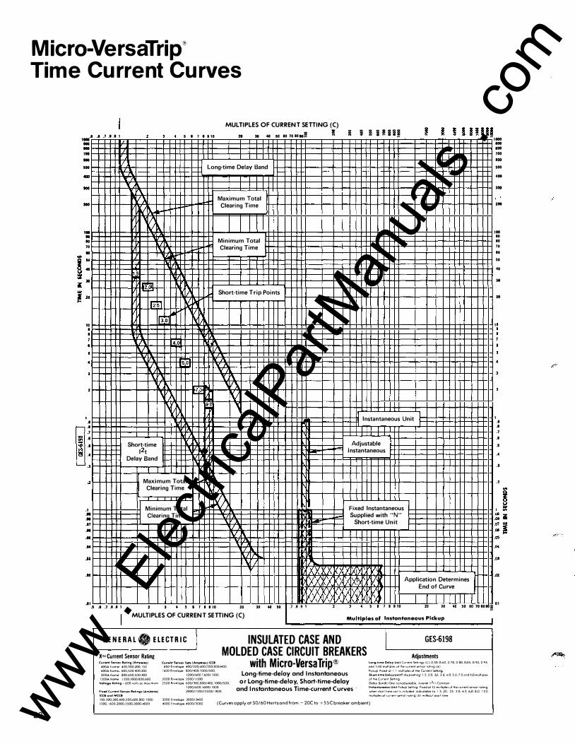
Micro-VersaTrip@ T ime Current Curves
MULTIPLES OF CURRENT SETTING (C)
1100 I I 7 I I 1 5 I 7 I 910 - -20 30 4G 50 107010108 ! ! ; : i !!i!
... ...
700 ... ... ... ... .. ,. .. ..
70 ..
10 I I
•
2
"' "' (\.
·� k'� f.-'��
. 5
lEi� �-� 112.;,
���� ,, 4.0 IV
\, \ " � \/
Long-time Delay Band
Maximum Total Clearing Time
I Minimum Total Clearing Time
I� Short-time Trip Points
�� v� I'< I/
1/\ 5.0
v '( � ljlo W\ rv
9. � I Instantaneous Unit I
7 I
• �: . . •
'
.2
.1
.01
..
.I 7 ... ... ... ...
Short-time 12t
Delay Band
Maximum Total Clearing Time
I I Minimum Total Clearing Time
'
'A �
X lA-IV�
' :x X
,I/!
Adjustable Instantaneous
Fixed Instantaneous Supplied with "N"
Short-time Unit
�X I'>' �xl'> {X ,'II lXI) l7 Application Determines �
� \1.11 lJ End of Curve
� v' I) n n ' \
-
1 .. . I .7 . 1.1 1 2 ' • • • 11110 20 3D .. " .7.8 .91 2 3 4 5 • 7 B 910 20 3D .. 50 80 708090� ..
I MULTIPLES OF CURRENT SETTING (C) Multiples of Instantaneous Pickup I
GEN ERA L . ELECTRI C I INSULATED CASE AND GES-6198
X= Current Sensor Rating MOLDED CASE CIRCUIT BREAKERS Adjustments Current Senoo• Raling (Am peres) CurrentSen1orTops(Amperes)ICCB with Micro-Versa Trip® long-hmeOelo�UnitCurrMtSettlng•(Cj·OS0.060, 070,080,085,090,095
400Af<ome 400,300,200,150 SOOEnvelope 400/200,600/300,800/400 and IOOmult,ple;o/Thecurrent<en•orrollng(X)
600Afrome 600,500,400,300 1600Envelope800/ 400,1000/500, Long-time-delay and Instantaneous
Pockup Foxed at I I mu lltp le< ofthe Current 5.etttng 800Afrorne 800,600,500,400 1200/600,1600/1000 Short-ttrne DelayUnit P,ckupsettt ng 15, 2 0,25,3 0, 4 0.5 0,7 0 ond9 0 mulltple< 1200A frame 1200,1000,800,600 2000Envelope2000!1200
or Long-time-deloy, Short-time-delay oltheCurr en tSettr ng
Voltage Rattng-600 volh a< moxtmum 2500Envelope600/300,B00/400,1000/500, Delay Bonds One nonod]ustoble,tnver,..12r=Con<tont
1200/600.1600/1000 and Instantaneous Time-current Curves · lnotontoneouoUnotPtekup5.etttng F1xedot 15multtplesolthecu"entsensor rohng
Fi•OK!CuJTentSenoorRattngo(Ampereo) 2000/ 1200/2500/1900 when,horl-ltme umt"'"duded Adjustable to I 5,20, 25 3 0, 4 0, 6 0,8 0, 1 0 0 ICCiondMCCI mulhples of current sM'<>t rohng (XI w•thout •nor! It me
150.200.300, 400,500,600,800 1000 3000Envelope3000/2400 (Curves apply at 50/60 Hertz and from- 20C to+ SSC breaker ambient) 1200,1600.2000,2500.3000,4000 4000Envelope4000/3000
20
1 ... ... . .. 700 000 .. . ... 300
200
1 .. .. ..
1
1
" .. " ..
" ..
.I
.I
.7
..
. . . . ..
.2
.. " 02
01
www . El
ectric
alPar
tMan
uals
. com

U: r Hi-Range Instantaneous "H" Suffix I -- 0.4 � II 11 !'.."" � Low Voll•gelc-1 Insulated Case 0.8 _J Power CirCuit r-- C1tcu1t Breaker
Breaker Total Total Clearmg 1.0 J Cleanng T1me Time
!'o.. """ 1 I I I I 7 / Application
" v /V Determmes End of Curve -...!'.. 'X L'/
'-,)....:: � X IXJ)(I lnstontoneous Adtustment P•ckup seM•ng 0 4 0 6 0 8 mull• pies of breaker short-t,me onterruptong ratrng 1 HI
� �X XIXJ)(J ' � I
.2 .J 4 .5 .6 .7.8.91 5 8 1 8 9 11
"' Q � � 1 "'
�: � 07 "'_2: ..... 05 .. 03
02
01 MULTIPLES OF BREAKER SHORT· TIME INTERRUPT ING RATING
���������1-�������--+-� 03
I'. X \ 7.0 � � 3! �!���t§l!!l���g�.o ����M.3x §�j§jj ': Short Time
Delay Bancio;
ln5tontaneous Ad1ustments P1ckup set ot ISX for 200 thru llr. \ Apphcatton �- 02
2000 amperes rol•ng l]X lor 2500 ampere1 and 3000 amperes ,_�
E Determmes
ei
-JF{]i;�j'
o'..;,'"i''�"9S'ro<:;"d;.,9q:X:;Io'='r'O:;;:OJ,O� om[7p:;e'; e;r:;er,e�w;r,"� ol;::m):,g
<:Yd)4{ E nd of Curve
. �,1!,�9� 1 �.h(D<�0.t::::.p�>£5!C�, ::,!-1,�,t:,h,d._L-,l,_ jU30 o1 MULTIPLES OF CURRENT SENSOR TAP SETTING, "X"
�jlow Voltage Power C1rcu1t Breaker Total Clearmg T1me
Standard Instantaneous
I I I "' Q z Molded Case and 0
lnsulat9d Case � c.rcu•t Breaker r:��=t�B 1 "'
Total Clear1ng � �: ! T1me 07 w
ri-k��-t�+--t-t-t+-�-+�+-�----�-+--�·· ,_! I").. 1 " ��ttl'' �" � Application P\'" 04
[/ V1 E�=t
=��·:;:e [: OJ 1/ / /
·" J-t-H+t--+-+-++++-i++++IH----1f--+---1f-f---j-+-I-I---HH-l-l .oz X X� LX.; lmtontoneor.a Ptckup setttng I S 2 0 3 0 4 0 6 0 8 0 and � r'){' ��g 0";,��:,����:" or H'r1\ur .�;�: )< 02
semor top 1ettong or rol1nq foo 4000 ampcw1 sensor
_01_5� .• �.,�.7, -:,�1!--..L-!---..L..L..LLJ-5L8LJ7Ll8 ..J9L1L0 _ _JL___2L0 _JL__30U-410_LJ5 0L8L0 J70L810J90.J� _01
H-f"\c�A.,j p,ckup settrng l S 2 U 30 4 I) j 0 7 0 clrld <.J 0 rnull•pic>l ,,f � X � .X )f)r ><I ji('j('}(1>( )( X � X X 01
1 8 i 1 2 J 4 5 I 1 I 110 20 MULTIPLES OF CURRENT SETTING, C MULTIPLES OF INSTANTANEOUS PICK UP
GENERAL . ELECTRIC I X=Current Sensor Tap Setting or Rating
(ulfeniSen;or Top• {Ampere<) LVPCB AK� Ill II){)/) �0/2 2�/lOO
(u,.mt Senoor Top•{Amp.,reo)ICCB BOOr,,.,l(,pe 40(),20061lOt300BOI''400
LOW-VOLTAGE POWER CIRCUIT BREAKERS TYPE AKR
INSULATED-CASE CIRCUIT BREAKERS TYPE TPV, THV
MOLDED-CASE CIRCUIT BREAKERS TYPES T J9V, THJ9V, TK9V, THK9V
with Micro-Versa Trip'
1 �;Jo, �Oo; ��:�;-, 1 600
HOO,I/c)Ot1Ml01/00il
IJ011il6illl'/000tl21111
1Nil';JOOO;JOOU 41100
1 t>OO f nv.,lnp� B 00/ 400 I 000 ' �·Oil
12tlil'NlOit>OOtlllllrl
.''100 t ,,.,.l<>f><' t>O() H0Pt400 I 0'.10 I �0()
1}00;6(){1160011000
F,.ed (u.,�nl Sen•or Rotongo {Ampere•) LVPCB 11111(1 [,",.lop<'
A�� l!l IOU I 'ltl .'.''• JOO 400 llUO 80U oU\10 I nv<'I<>P>
liii140Ut>iiOBOlllllllll600
!1001Jilil16002Ll<lll
1'(\()l(,))(llfllilliJ()(t
1�110 /000 lOOO 4000
Fo .. td CurrentSemor Rol•ng• (Amperes) JCCBondMCCB : 'llJ 100 JUO 41111 'JOG 600 �01' lOll()
I /110 1600 1000 •1 �00 JUDO 4000
Long-time-delay, Short-time delay, and Instantaneous Time-current Curves
(Curves apply at S0/60 Hertz and from - 20( to +sse breaker ambient 20C to + 70( lpro9rammer ambient)
I GES-6199 Programmer Adjustments
Long Trme Delay Unrt c�,oent St•ll•ngl 1C' Ll :,\) (l bll ll 7<1 0 80 0 8') 0 90und I OC ol1LJit.nlt''Cicuol(•nl ll'""" lop"•ll,ll) or ootonq { XI r,,lwp il8 ll v ! () I I ""d'•pl<'' ,,r th<·
( "'"'nl <,,H•nq 1( I Df'loy f>or1d1 I } 1 nnrl �
Short Tome Delay Unrt Potkup Sellrflgl I ) 2 0 } ) 3 0 4 U ) 0. 7 0. ond 9 0 multople1 of< urrenl \e"'"9 (C I
Delay 8ond5 MIN INT MAX; I t Cnr111on1
ln5tantaneou• Adjullmen� )ee Curve\ obove
lO
21 www . El
ectric
alPar
tMan
uals
. com
22
' 1000 ... ... 100 10 50
0 0
•• 0 300
20 0
100 .. 0 0 .. "' Q ' 0 � ..
111 "' 0 \! i 2 0 ..
0 I I 1 • ' •
'
2
•
�. . .
I 1 • ' •
'
.2
.1 .. • 1
.09
.05 ••
D3
.a 2
.. 1
I 1 I 91
\ 1\\
T \,\..
� v
../ "
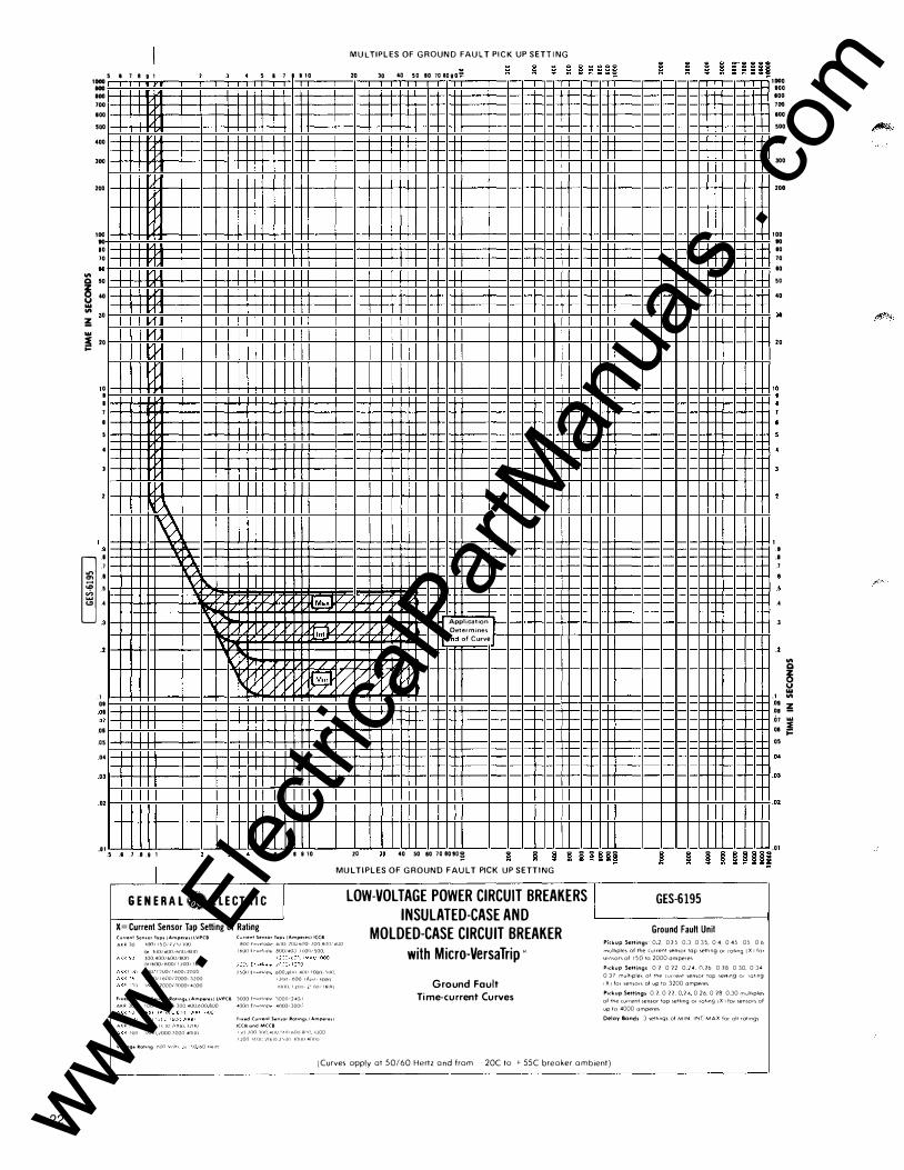
MULTIPLES OF GROUND FAULT PICK UP SETTING
5 I 7 11 110 20 30 4tJ 50 10 708090° - - -
� / / 1 �:���::�:: r � /V (End of Curve 1
� I( // � 01 �
V/ /1/
.5 .I .7 .8.91 5 8 7 I 910 20 " 0 40 50 80 70 80!0� 0 0 0 0 0 0 00 0
MULTIPLES OF GROUND FAULT PICK UP SETTING
GENERAL ij ELECTRIC I X= Current Sensor Tap Setting or Rating CunentScn<orlop<{Ampere<)LVPCB AKR10 HXl/1)0/U'l;iOO
Ofl<J0/400ti>OOtBOO
300,400/1>001800
oriWO!H00/1200/11>00
HOO,l?IJ0/1600t7000
1200/1600/?000·3200
ll>lJ0·?0001JI)0014cl00
CurreniSen•orTop< (Ampere<jl((ll 8()() fnv�lop(' 4110• }()() 6(10 JQ() 8()(),'400
i600 f rv�•ope 8001400 11100, 500
}�l){) tn•<>lnp<· 600 H(HI 4lltl 10()(), ',()()
1}(11" 600 I �I HI• 1()()1) !!){){),ll1JIIi:'ll0'1HOIJ
Foxed Curro•nl Ser,.or l!otong• (Ampere•) lVPCB 3000 f�v�lnp,. l000'240tl
AKR 30 100 ''>0 J?', 300 400 600 BOO 4000 fnv�'"P<> 4()00•3001•
A�R ?'i II. Jl' )I)()<) lliXJ
I()O 10illll000300040{)()
Volt"9" 11otong ;,()() Volt1 1C 'J0t60 H�•t1
Foxed(u,.entSen•orl!olong>IAmp.,re•l ICCBondMCCB
1'lll100l(\()4(){)'><1(1<'>01lH(\()1,)00
1)00 lf.(lC �()Ill) )'oi)() \01111 4(1{11>
GES-6195 LOW-VOLTAGE POWER CIRCUIT BREAKERS I INSULATED-CASE AND L---------1
MOLDED-CASE CIRCUIT BREAKER
with Micro-Versa Trip'
Ground F ault Time-current Curves
Ground Fault Unil Ptckup Setting�· 0 2.025 03 035,04.045 05 0 6 rnultoples of the current sen1or tap settmg Or rotong I X 1 for
1emor1 of ISO to 2000 ampere> P�ekup Settmgs 0 2 0 22 0 )4 n 26 0 28 0 30. 0 34 0 37 mull>plel of the current sensor top sett1ng or ral•ng 'X r for sensors of up to 3200 amperes P.ckup Settmgs 0 2. 0 22 0 24 0 26.0 28 0 30 multoples of the current sensor top sett•ng or rotong 1 X 1 lor sensors of up to 4000 amperes Delay Bands 3 settmql of MIN INT. MAX for all rot1ngs
(Curves apply at 50/60 Hertz and from 20C to +- SSC breaker ambient)
1 000 000 100
1
1
1
100 100 500 400 300
200
.. .. 10 10 .. 50 ••
"
20
.I ..
.1
.. .. .. .2
.1
"' Q 8 111 "'
::! 01111 08 ! 05 .. D3
"
.0
�
www . El
ectric
alPar
tMan
uals
. com

Micro-VersaTrip® 4 & 9
Interrupting Capacities
Table 23.1-Micro-VersaTrip® Circuit Breakers
AC Breaker Frame Symmetrical
Volts Designation Interrupting Capacity
TJ 42,000 240 THJ 65,000
TK 42,000 THK 65,000
TJ 30,000 480 THJ 35,000
TK 30,000 THK 50,000 TJ 22,000
600 THJ 25,000 TK 22,000
THK 25,000
Available Current-Sensor Ratings
150, 200,300,400, 500,600
400,600,800,1000,1200
150, 200,300,400, 500,600
400,600,800,1000,1200
150, 200,300,400, 500,600
400,600,800,1000,1200
23 www . El
ectric
alPar
tMan
uals
. com

Micro-VersaTrip'B' 4 & 9
Selection and Ordering
How to Order:
Select bas ic breaker from breaker catalog n u m ber tables 25. 1 , 25.2 and 25.3 and th is w i l l be suppl ied as a factory assem bled u n it .
I f standard program mer functions are req u i red no change to the catalog n u m ber is needed. I f optional functions are req u i red add appropriate tr ip characteristic suff i x from prog ram mer tables 26. 1 and 26.2.
Add suff ix "WL" fo r CU AL l i ne and load l ugs when req u i red . Basic breaker suppl ied less l ugs. See table 27.2 for avai lable l ugs fro m l ug suff ix table. Combi nat ions of l ine and load lugs are ind icated. When a neutral cu rrent transformer for 3Ph 4W or 1 Ph 3W g round fau lt is req u i red , select by separate catalog n u m ber f rom Table 27. 1 .
Se lect accessories by i nd iv id ual catalog n u m ber from their respective prod uct tables.
Complete order shou ld read as : THJ9V2606NGWL, TSRG206 and TVST1 2RS
Example:
THJ9V2606
NG
WL
TSRG 206
TVST1 2RS
Catalog Number Construction TH J 9 v 2 6 06 NG WL
Current interrupting capability T = standard break TH = h i g h break
T
Frame Type __________ ___J
J or K
Programmer type ----------4 = M i cro-VersaTri p 4 funct ion 9 = M i cro-VersaTri p 9 fu nction
Frame Rating ____________ __,
VV = 1 00% eq u ipment rat ing V = Standard Rated
Ampere Rating of Frame---------_J 1 = 400A 2 = 600A 3 = 800A 4 = 1 200A
Breaker Voltage Rating __________ ___,
6 = 600V ac
24
L_ Terminals (Blank) = Less Lugs
WL = cu/AI l i n e and load lugs
'----- Programmer Functions 4 function M i cro-VersaTri p
B lank (STD) N
G or G R 9 funct ion Micro-VersaTri p
B lank (STD) S or D or N
L T
G or G R A 1 or A2 o r A3 or A
Z1 or Z2 or Z
'------ Continuous Current Rating Sensor Amperes
01 = 1 50A 05 = 500A 02 = 200A 06 = 600A 03 = 300A 08 = 800A 04 = 400A 1 0 = 1 000A
1 2 = 1 200A
www . El
ectric
alPar
tMan
uals
. com

Micro-VersaTripB 4 & 9
Selection and Ordering
Table 25.1-4 Function Micro-VersaTrip� UL Listed. Supplied Less Lugs. For Lugs Add Suffix WL.
Fra me Sensor Br ea ker Cat. N o. 1 1 1
Siz e Rat ing Std . Br ea k
J400 1 50 TJ4V1 601 200 TJ4V1 602 300 TJ4V1 603 400 TJ4V1 604
J600 1 50 TJ4V2601 200 TJ4V2602 300 TJ4V2603 400 T J4V2604 500 TJ4V2605 600 TJ4V2606
KBOO 400 TK4V3604 600 TK4V3606 BOO TK4V360B
K 1 200 400 TK4V4604 600 TK4V4606 BOO TK4V460B
1 000 TK4V46 1 0 1 200 TK4V461 2
Table 25.2-9 Function Micro-VersaTrip� UL Listed. Supplied Less Lugs. For Lugs Add Suffix WL.
Fra me Sensor Siz e Rati ng
J600 1 50 200 300 400 500 600
K1 200 400 600 BOO
1 000 1 200
Br ea ker Cat. N o. 1 1 1
THJ9V2601 THJ9V2602 THJ9V2603 THJ9V2604 THJ9V2605 THJ9V2606 THK9V4604 TH K9V4606 THK9V460B THK9V461 0 THK9V461 2
H i-Br ea k
THJ4V1 601 THJ4V1 602 THJ4V1 603 THJ4V1 604 THJ4V2601 THJ4V2602 THJ4V2603 THJ4V2604 THJ4V2605 THJ4V2606 THK4V3604 TH K4V3606 THK4V360B THK4V4604 THK4V4606 THK4V460B THK4V461 0 THK4V461 2
'D en ...... (]) ctl ......
'O ::::J C +-' ctl ctl ...... (]) (J) LL
- Cf) ctl (]) c ,_ O ::::J
·- ...... +-' ctl Q. (]) O u_
...... (]) ctl E en c E c 0 ctl .Q ...... ,_ _ '0 O'l Q. '0 o o <C Q:
1 50- 1 200 Am peres, 600 Volts ac, 3-Pole , 50/60 Hz
Table 25.3-9 Function Micro-VersaTrip� 1 00% Equipment Rated UL Listed .
Fra me Sensor Siz e Rat ing
J600 1 50 200 300 400 500 600
K1 200 400 600 BOO
1 000 1 200
Br ea ker Cat. N o. 1 1 1 121
THJ9VV2601 THJ9VV2602 THJ9VV2603 THJ9VV2604 THJ9VV2605 THJ9VV2606 THK9VV4604 THK9VV4606 THK9VV460B THK9VV461 0 THK9VV461 2
1" Add trip characteristic suffix letter(s) for optional programmer functions.
121 Supplied with back connected assembly.
9 Fu nct ion B reake r
• Adjustable Current Sett ing
4 Fu n ct ion B reaker
• Adjustable Cu rrent Sett ing
• Long-Time Timing Light • Long-Time Timing Light • Adjustable lnstantan·eous
Pickup • Adjustable Long-Time
Delay
• Adjustable Ground Fault Pickup and Delay
• Short-Time -Adjustable Short-Time
Pickup with Short-Time Delay 12t Ramp and Fixed Instantaneous
-Adjustable Short-Time Pickup and Delay
-Adjustable Short-Time Pickup and Delay with F ixed Instantaneous
• Adjustable Long-Time P ickup and Short Time Ft Switch
• Zone Selective Interlocki n g on Short-Time and G round Fault
• Local and Remote Fault Ind ication Targets on Overload , Short Circu it and Ground Fault
• Remote Lon g-Time Timing Light
• Adjustable Instantaneous Pickup
• Adjustable Ground Fault Pickup and Delay
• Short Time -Adjustable Short-Time
Pickup with Short-Time Delay Ft Ramp and Fixed Instantaneous
25 www . El
ectric
alPar
tMan
uals
. com

Micro-VersaTrip® 4 & 9
Selection and Ordering
Table 26.1-4 Function Micro-VersaTrip Characteristics (From Table 25.1 )
Long Time
Short Time
l nstanta-neous
Ground Fault
• Adj ustable Cu rrent Setting (C)
Fixed Long-Time Picku p (1 . 1 C)
Fi xed Long-Ti me Delay
Long-Ti me T im ing L ight
• Adj Short-T ime Pickup
Short-Time Delay 12 t ram p
• Adj I nstantaneous Pickup
• Fixed I nstantaneous Pickup
• Adj Ground Fault P ickup 1 1 1 - Zero Sequence
- Ground Return
• Adj Ground Fau l t Delay
St and ard P rogramme r
X
X
X
X
X
11> F or 1 P H , 2 W - 1 P H , 3W-3P H , 3W-3P H , 4W systems. O rder neutral
transformer by catalog n u m ber when neutral is present.
N
X
X
X
X
X
X
X
O pti on al P rogramme rs
G GR NG NGR
X X X X
X X X X
X X X X
X X X X
X X
X X
X X
X X
X X
X X
X X X X
Table 26.2-9 Function Micro-VersaTrip®Characteristics (From Tables 25.2 and 25.3)
Long T ime
Short T ime
l nstanta-neous
Ground Fault
Other Fu nctions
Programmer Functions
• Adj ustable C u rrent Sett ing
• Adj Long-Ti me P ickup
• Adj Long-T ime Delay
• Long-T ime T im ing L ight
• Remote Long-T ime T iming L ight
• Adj Short-T ime Pickup
• Adj Short-Time Delay
• Short-T ime Delay 12t ramp
• Short-T ime 12t Switch 1 1 1
• Adj I nstantaneous P ickup
• F ixed I nstantaneous
• Adj Ground Fault Pickup 12 1
- Zero Sequence -Ground Return
• Adj Ground Faul t Delay
• Tri p I n d ication Targets -Overload & Short C ircu i t
-l ocal on ly -local and remote
-0/L, S/C and Ground Fau lt 131
-local only -local and remote
• Zone Selective I nterlock 141 -Ground Fau lt 131
-Short Time 1 11
111 A dj u sta ble Sh ort-T i m e D elay is req u i red.
STD No Suffix
X
X
X
X
Alternate Opti on al Functi ons
Programmers Add to Standard or Alternate Programmer (Suffix)
s 0 N L T G GR A1 A2 A3 A Z1 Z2
X X X
X
X X X
X X X
X
X X X
X X
X
X
X
X X
X X
X X
X X
X X
X X
131 G ro u nd F a u l t R eq u ired.
141 TIM1 -interlock m od u l requ ired-one per system. G ro u nd 121 F or 1P H , 2W-1P H , 3W-3P H , 3W-3P H , 4W systems. O rder neutral
transformer by catalog n u m ber when neutral is present. F ault and S h o rt-T ime req u ire separate modules. O rder separately.
26
z
X X
www . El
ectric
alPar
tMan
uals
. com

Micro-VersaTrip® 4 & 9
Selection and Ordering Neutra l Cu rrent Transfo rmers for 3-P hase, 4-Wi re G ro u n d
Table 27.2-Lug Catalog Numbers
Fau lt Systems
Table 27.1-4 & 9 Function Micro-VersaTrip ®
Bre ake r A mpe re s C at . N o. Type
1 50 TSRG 201 200 TSRG 202
I 300 TSRG 203 " 400 TSRG 204 500 TSRG 205 600 TSRG 206
400 TSKG 404
Bre ake r Type
J 4 and 9
Function
K 9 Fun ction
Only
K
4 Fu nction Only
Sen sor A mpe re St and ard Lu gs Opti on al Lu gs R atin g cu/AL cu only
1 50 200 300
TCAL43 TC043
400
500 TCAL63 TC063
600
400 600 TCAL81 TC08 1 A 800
1 000 TCAL 121 TC0121
1 200
400 TCAL81-L ine TC08 1 A-Line
600 TCAL91 -Load TC091 -Load
800
1 000 TCAL 1 21 -L ine TC01 21 -L ine 1 200 TCAL 131 -Load TC01 31-Load
Lu g C ove rs
-
-
286A8066G-3
286A8066G-1
286A8066G-3
286A8066G- 1
600 K 800
TSKG 406 TSKG 408
Lug covers supplied on al l K Frame Breakers when ordered with lugs. End cover (286A8066G-2) supplied on K Frame Breakers when o rdered less lugs.
1 000 TSKG 410 1 200 TSKG 4 1 2
Micro-VersaTrip® 4 & 9
Accessories
I nte rnal l y M o u nted Si g naling and Co n t ro l
Table 27.3-Available Accessories-UL Listed When Factory Installed for Use in All J and K Frame Micro-VersaTrip®Breakers.
P ole Le ad Acce ssory M ountin g Exit In st all ati on
Left Cente r Ri ght Side 1'} Bac k 12}
Auxi l iary - - """ Switches
Shunt - - """ Trip
Blown Fuse """ Trip
- -
Bell Alarm - """ -Switch
Undervoltage - - """ Release
Combination Shunt Trip - - """
with Aux. Sw.
Com bination Under Voltage - - """ with Aux. Sw.
1 1 1 Standard lead exit right side except bell alarm with lead exit left side.
""" """
""" """
""" """
""" """
""" """
""" """
""" """
121 Optional specify B suffix after accessory catalog number. (Applies only to J Frame.)
Tot al Nu mber of Acce ssorie s
Within Any One Ci rcuit Bre ake r
Any One Plus Bel l
Alarm
27 www . El
ectric
alPar
tMan
uals
. com

Micro-VersaTrip@ 4 & 9
Accessories
Shunt Trip A Shunt Tr ip Device can be used to tr ip and open a breaker by remote contro l . When the breaker opens, the shunt trip coi l circuit is de-
energized by means of an auxi l iary switch. Meets U/L req u i rements for operation at 55% of rated voltage for use on ground fault systems.
Table 28.1-Shunt Trip
Shunt Trip Cat. N o. AC
TVST7RS
TVSTBRS
TVST9RS
TVST1 1 RS
TVST1 2RS 1 20V
TVST1 3RS
Undervoltage Release (UVR)
240V
480V
600V
The Undervoltage Release instantaneously trips the breaker when voltage drops to 35-70% of normal rati ng . The device re-trips the breaker if it is c losed before normal voltage is restored .
Time-delay Unit-For use with UVR Prevents n u isance tr ipping due to momentary loss of
Auxiliary Switch
These switches operate ONOFF i nd icati ng l ights, relay and control c i rcu its as a function of breaker ON-OFF
28
V oltag e In stru cti on s
DC
1 2V
24V
48V
250V G EH-4623
1 25V
voltage. Separate external ly
mou nted u nit has 1 20 volt ac i nput and 1 25 volt d e output with delay adjustable from .1 to .5 seconds. Used in conjunction with 1 25 volt de undervoltage release, which must be ordered separately. U nit mounts external to the breaker. Cat. No. TD1 1 OA530. For t ime delay of . 1 to 1 .0 sec order Cat. No. TD1 000.
posit ion. Switch is SPOT rated six amperes at rated volts ac; Y2 ampere at 1 25 volts d e ; % ampere at 250 volts de .
I nte rnal ly M o u nted Sig nal i ng an d Co n t ro l
Table 28.2-Undervoltage Release
Und erv oltag e V oltag e
Cat. N o. AC DC
TVUV1 RS 1 20V
TVUV2RS 240V
TVUV3RS 380V
TVUV4RS 480V
TVUV6RS 600V
TVUV7RS 1 2V
TVUVBRS 24V
TVUV9RS 48V
TVUV 1 0RS 1 25V
TVUV1 1 RS 250V
Table 28.3-Auxiliary Switch
Auxi liar y Swit ch Cat. N o.
TVAS2AB2RS
TVAS2AB4RS
TVAS6AB2RS 1 1 1
TVAS6AB4RS 1 1 1
1 ' 1 Not U L listed.
N o. of S ing le-P ol e,
Dou ble Thr ow Swit ch Rating Swit ch
E lement s
2 6A-250V ae 1 /2A-1 25V de
4 1 /4A-250V de
2 6A-600V ae 1 /2A-1 25V de
4 1 /4A-250V de
In stru cti on s
G EH- 4623
In stru cti on s
G EH-4623
www . El
ectric
alPar
tMan
uals
. com

Micro-VersaTrip® 4 & 9
Accessories
Bell Alarm These switches are used to indicate a breaker trip. Wi l l not activate when breaker is manual ly operated.
Switch is SPOT, rated five
Blown Fuse Trip
P rovides s ing le-phase p rotection for fuse and ci rcu itbreaker combi nations,
amperes at 240 volts ac non-inductive, one ampere, 1 20 volts ac inductive, 2 .5 amperes at 28 volts de inductive.
factory instal lation on ly. Su itable for system voltages of 208 to 600 volts ac.
I nternal l y M o u nted Sig nal i n g and Co n t ro l
Table 29.1-Bell Alarm
Bell Alarm Sw itch Sing le Po le
Cat. No. Dou ble Th row Sw itch Rating
TJVBALS 5A-250V ac TKVBALS 2.5A-28V d e
Table 29.2-Biown Fuse Trip
Blown Fu se Trip Vo ltag e Cat. No.
208V ac TVBFD31 6RS to
600V ac
Table 29.3-U V R/Auxiliary Switch Combination Accessory Consists of an under voltage release and a two stage auxi l iary switch.
Combination Accessory Consists of a shunt trip and a two stage auxi l ia ry switch.
Co mbin ation Und ervo ll aie/
2-250V Aux . WS.
TV2AB2UV1 RS
TV2AB2UV2RS
TV2AB2UV3RS
TV2AB2UV4RS
TV2AB2UV6RS
TV2AB2UV7RS
TV2AB2UV8RS
TV2AB2UV9RS
TV2AB2UV1 0RS
TV2AB2UV1 1 RS
1 1 1 Not U L listed.
Co mbin ation Vo ltag e Und ervo ltag e/ 111
2-600V Aux. Sw s. AC
TV6AB2UV1 RS 1 20V
TV6AB2UV2RS 240V
TV6AB2UV3RS 380V
TV6AB2UV4RS 480V
TV6AB2UV6RS 600V
TV6AB2UV7RS
TV6AB2UV8RS
TV6AB2UV9RS
TV6AB2UV1 ORS
TV6AB2UV1 1 RS
Table 29.4-Shunt Trip/ Auxiliary Switch Combin ation Shun t Trip/
2-250 V Aux. Sw s.
TV2AB2ST7RS
TV2AB2ST8RS
TV2AB2ST9RS
TV2AB2ST1 1 RS
TV2AB2ST1 2RS
TV2AB2ST1 3RS
1 1 1 Not UL listed.
Co mbin ation Shun t Trip/ 1 1 1
2-60DV Aux. Sw s.
TV6AB2ST7RS
TV6AB2ST8RS
TV6AB2ST9RS
TV6AB2ST1 1 RS
TV6AB2ST1 2RS
TV6AB2ST1 3RS
Vo ltag e
AC
1 20V
240V
480V
600V
DC
1 2V
24V
48V
1 25V
250V
DC
1 2V
24V
48V
250V
1 25V
In stru ction s
G EH-4626 G EH-4663
In stru ction s
G EH-4624
In stru ction Sh eet
GEH-4623
In stru ction Sh eet
GEH-4623
29 www . El
ectric
alPar
tMan
uals
. com

Micro-VersaTrip(' 4 & 9
Accessories
Exte rn a l ly M o u nted H a n d l e Operat i n g Mech a n i s m s
TOR Rotary Operating Handle
The Rotary-Operat ing I ntegral Handle mou nts d i rectly to the breaker, and operates through the door of the enclosure. A mechan ical interlock prevents u nauthorized opening of the enclosu re when the handle is in the ON positio n . The locking hasp accommodates u p to three pad locks. Su itable for hor izontal ly or vert ical ly mou nted breakers. For N EMA 1 and N EMA 12 enclosures.
TOM Adjustable Depth Handles
TOM Door-Mou nti ng Hand les are avai lable in shal low mount ing types and extended shaft type for vert ical or h orizontal breaker mounting. Mechanism provides interlocking . The door-mou nted handle accommodates u p to three pad locks. Su itable for N EMA 1 and N EMA 1 2 enclosu res. NOTE: A pendulum-type handle designated Cat. No. THCH45 is also avai lable for NEMA 4 and 5 enclosu res.
Table 30. 1-TDR Handle Mechanism Catalog N umbers
TDF Safety Handle
TDF Safety Handle Mechanisms are designed to meet auto motive, mach ine tool manufactu rers' and contro l pane l b u i lders' requ i rements. Inter lock p revents enclosure opening with handle ON. Avai lable for thru-door or th ru-flange operat ion , rig ht- or left-hand mount ing . Vau lt-type hardware avai lable . For mou nting in enclosu re depths through 1 9962 i nches.
Circuit I nstructio n Provisio n For I nstructio n
Breaker Vert. Horiz. Kirk Key I nterlock Types
Sheet No. (Add Suffix) 1 ' ' Sheet No.
J T JVR1 B TJVR1 HB G EH-4629 -KLP G EH-4634
K TKVR1 B TKV R 1 H B GEH-4633
( 1 ) Kirk Lock must be supplied by customer. Accepts Kirk Key Lock Type " "FN" with one-inch bolt extension and key removable when bolt
extended (circuit breaker in OFF position).
Table 30.2-Accessories for TOR Handle Mechanisms
Circuit Door Ri ng Gasket I nstructio n Breaker I nterlock Kit Sheet No. Types Catch Kit
J 343L483G7 792A484G2 G EH-4638
K 343L483G8 792A484G3
30 www . El
ectric
alPar
tMan
uals
. com

Table 31.1- TOM Handle Mechanism Catalog Numbers
Breaker Box C ompl ete Op erati ng
H andl e I nstru cti on M ech ani sm T yp e D ep th M ech ani sm O nl y O nl y Sh eet N o.
J Shal low TJVHM1 TJVOM1
TH2 G EH-4632 Extended TJVHM2 TJVOM2
K Shal low TKVHM1 TKVOM1
TH2 GEH-4318 Extended TKVHM2 TKVOM2
Table 31.2- TDF Handle Mechanism Catalog Numbers
Ci rcui t Encl osu re Breaker
(Jl��) T yp e
J4 1 ' 1 2 4 14)
J9 1 ' 1 2 4 14)
K4 1 , 1 2 4 141
K9 1 ' 1 2 4 14)
Basi c H andl e and Op erator
RH M ou nti ng
THFV3 121
THFV355 121
THFV30 121
THFV30SS 121
TH FV4 131
TH FV4SS 131
THFV40 131
TH FV40SS 131
LH M ou nti ng
THFV3L 121
THFV3SSL 121
THFV30L 121
THFV30SSL 121
THFV4L 131
TH FV4SSL 131
THFV40L 131
THFV40SSL 131
M ou nti ng Pl ate For Th rou gh D oor M ou nti ng 1 ' 1
Sh ort L ong
- 343L531G2
343L53 1 G 1 343L531G2
- 343L531 G 2
- 343L53 1 G2
1 1 1 Thru-door mounting is not recommended for oil- and water-tight applications. For thru door mounti n g , order escutcheon Catalog Number 343L530G2.
121 6-1 7/32-in. min . to 1 9-9/32-in max. mounting depth. 131 8-5/32-in . min. to 1 9-9/32-in. max. mounting depth. 141 Stainless steel external parts.
Table 31.3-Accessories for TDF Mechanisms
Breaker Ad ap ter f or R emote Op erati on
T yp e RH M ou nti ng I LH M ou nti ng
J , K THFVRA I THFVRAL
Table 31.4-Auxiliary Switches for All TDF Mechanisms ( 1 J
V ari abl e D ep th Fix ed D ep th Auxili ary Swi tch R ati ng D oubl e Th row
RH Mi g RH Mi g LH Mi g LH Mi g
Single Pole 343L533G2 343L533G1 343L533G4 343L533G3 Double Pole 343L533G6 343L533G5 343L533G8 343L533G7
V ol tage
1 20V} 240V 480V
ac
600V 1 25V } 250V
de
Si ngl e P ol e D oubl e P ol e (A mp s) (A mp s)
1 5 3.0 1 0 1 .5 6 1 .0 5 0.8 0.5 0.2 0.2 0.1
I nstru cti on Book N o.
GEH-4528
GEH-4529
Table 31.5-Door Hardware For Flange-mounted T D F Mechanisms ( 1 J (2J
For NEMA 1 & 1 2 For N EMA 4 use 131
1 1 1 Not UL l isted.
I nterl ocki ng V aul t T yp e wi th 2-p oi nt R oll er
L atch es and 4" H andl e
RH Mi g LH Mi g
343L513G1 343L51 3G2
343L513G8 343L51 3G9
121 Interlock kit for double doors, Cat. No. 343L574G 1 . 131 Stainless steel external parts.
Auxili ary R oll er L atch L ong 6" N on-i nterl ocki ng V aul t- typ e wi th tw o-
For 3 rd P oi nt L ocki ng D oor H andl e p oi nt roll er l atch and f ou r-i nch h andl e f or u se on second ary d oors
RH Mi g LH Mi g RH or LH RH Mi g LH Mi g
343L513G3 343L513G4 343L51 3G5 343L513G6 343L51 3G7
343L513G10 343L51 3G 1 1 343L513G12
31 www . El
ectric
alPar
tMan
uals
. com

Micro-VersaTrip® 4 & 9
Accessories
External ly M o u nted H an d l e Operat i n g M echan isms
Motor-Operated Mechanism A motor-operated mechanism can open, close or reset a breaker, remotely. This convenient attach ment mou nts i ntegral ly with the breaker, without mod ification to the breaker or its handle. Just l i ft the cover of the accessory mechanism to operate the breaker manua l ly . Breaker ON-OFF is ind icated in the operating mechanism cover.
Table 32.1
Bre ake r Type
J
K
Cat. N o.
TJVMOMA1
T JVMOMA2 111
TJVMOMA8
TJVMOMA9
TKVMOMA1
TKVMOMA2 1 1 1
TKVMOMA8
TKVMOMA9
1 1 1 For 208V ac use 240V ac device.
Volt s
1 20V ae
1 25V de
240V ae
250V de
24V de
48V de
1 20V ae
1 25V de
240V ae
250V de
24V de
48V de
I nst ru cti on Sheet
GEH-4582
G EH-4583
Table 32.2-SOOV ac-Auxiliary Switch-Not UL Listed
N o. of SPO T Fie ld l nst al lable Cat. N os.
Remote Operating
Fact ory In st alled Cat. N os.
Sw it ch E le ment s Bre ake r En ve lope Size (Ampere s)
11 1 Field installed aux. switches and shunt tr ips must mount o n opposing poles o n ly.
121 Mounts in right pole only when shunt trip specified.
131 Not avai lable on breakers equipped with a shunt trip.
32
1 2 3 4 5 6 7 8 9
1 0 1 1 1 2
BOO, 1 600 & 2000 121
TPAS6AB1 TPAS6AB2 TPAS6AB3 TPAS6AB4 TPAS6AB5 TPAS6AB6
-
-
-
-
-
-
3000 & 4000 1 1 1
TSAS6AB1 TSAS6AB2 TSAS6AB3 TSAS6AB4 TSAS6AB5 TSAS6AB6
-
-
-
-
-
-
BOO, 1 600 & 2000 3000 and 4000
TPAS6AB1 S TSAS6AB1 B TPAS6AB2S TSAS6AB2B TPAS6AB3S TSAS6AB3B TPAS6AB4S TSAS6AB4B TPAS6AB4S TSAS6AB5B TPAS6AB5S TSAS6AB6B TPAS6AB7S TSAS6AB7B TPAS6AB8S TSAS6AB8B TPAS6AB8S TSAS6AB9B TPAS6AB1 0S TSAS6AB1 0B TPAS6AB 1 0S 13> TSAS6AB 1 1 B 131
TPAS6AB1 2S 131 TSAS6AB 1 28 131
www . El
ectric
alPar
tMan
uals
. com

Micro-VersaTrip® 4 & 9
Accessories
Back Connected Studs
Studs are supported by a sub-base, but make positive contact with each line and load term i nal . Once fastened to su b-base, a stud no longer has to be removed to remove or i nsta l l breaker. Requ i res insulated mounti n g plate.
Plug-in Base Assembly Plu g- in Base Assembly provides for qu ick changeout of breakers. Breaker p lug- in terminals a l ign with terminals on one-piece backplate assem bly.
Each plug-in mounting base assembly inc ludes al l mounting hardware, studs, and male or female connectors for attachment to one end of breaker.
Studs are of d ifferent length so by using p roper combinations of PD1A and PD2A u n its, adequate electrical spacing wi l l be
Table 33.2
assured between adjacent breakers, i .e . , a short- longshort (SLS) u ni t must be used adjacent to a longshort-long (LSL) un it .
The optional mounting plate (TMP3, etc . ) is supp l ied at no cost when ordered with a pair of plugin mounting bases. It accurately locates and supports the l i ne and load p lug- in mounting-base assembl ies, provides conven ient means to attach the enti re unit to a metal structure, and serves as a deadfront barrier.
Plu g In Mount ing Ba se-2 Requ ired P er Brea ker
Circu it Am pere No. Sta b Co nf igu rat ion Cata lo g No.
Brea ker Ty pe
Rat ing Po le s P01 PD2
400 2 sos LOL T J 42 PD 1 A, 2A
J 3 SLS LSL TJ 43 PD 1 A, 2A
600 2 sos LOL TJ 62 PD 1 A, 2A 3 SLS LSL TJ 63 PD 1A, 2A
600 2 sos LOL TK 62 PD 1A, 2A 3 SLS LSL TK 63 PD 1 A , 2A
800 2 sos LOL TK 82 PD 1A, 2A
K 3 SLS LSL TK 83 PD1A, 2A
1 000 2 sos LOL TK 1 02 PD 1 A, 2A 3 SLS LSL TK 1 03 PD 1A, 2A
1 200 2 sos LOL TK 1 22 PD 1A, 2A 3 SLS LSL TK 1 23 PD 1 A , 2A
M o u nt i n g M eans
Table 33.1
Circuit Am pere L ength, Bac k of Brea ker Cata lo g
Ty pe Rat ing Brea ker in Inch es Num ber
J 400 5 1 7/32 TJK1 600 5 1 7/32 TJK2
400 5 1 /2 TKM9
K 600 5 1 /2 TKM 1 0 800 5 1 /2 TKM 1 1
1 200 8 TKM1 2
O pt io nal Mount in g Plat e
Catalo g No. In st ruct io n
4 Fu nct io n 9 Fu nct ion Boo k No. M ic ro M ic ro
TMP3 TMP6 GEH-4342
TMP4 TMP7 GEH-4342
33 www . El
ectric
alPar
tMan
uals
. com

Micro-VersaTrip® 4 & 9
Accessories
Drawout Assembly
The d rawout mechanism is designed for heavy d uty appl ications in load center un it substations, motor control centers and switchboards in i ndustr ia l , commerc ia l , and inst itutional bu i ld ings. It permits rapid examination and maintenance of ci rcuit breakers without havi ng to deenerg ize the switchboard bus structu re.
All d rawouts have fou r d iscreet posit ions: engaged, test, d isengaged and fu l ly withdrawn. Provisions are provided for padlocking the carriage in each of these positions. Mechanical i nterlocking is also b u i lt i n to prevent the movement of a closed breaker into or out of the engaged or test positions. Each beaker position is clearly identif ied .
The racking handle is an integral part of the d rawout frame. Al l main and secondary contacts are self-al igning. The carriage may be hand rotated 1 80 degrees on the rai ls for contact mai ntenance or inspection.
Al l d rawouts (except where noted otherwise) are UL l isted .
Ordering Information
The drawout may be ordered as a comp lete assembly, carriage only or stationary frame on ly. The complete assembly consists of stationary frame and carriage. The carriage must be factory assembled to the c i rcuit b reaker. Breakers and breaker related options are ordered separately.
When the complete d rawout assembly or carriage only is ordered with the
D rawou t Asse m b ly
breaker. secondary disconnects are suppl ied as req u i red for control and accessory wir ing . The breaker w i l l be factory i nstal led and u n it sh ipped complete un less otherwise specif ied.
Secondary d isconnects are not suppl ied when d rawout frames are o rdered separately. They are , however, suppl ied as requ i red for carriage and breaker.
Vertical bus con nectors are provided as standard . For horizontal connectors, add suffix " H " to catalog number.
When ordering the 1 00% rated d rawout specify the standard UL l isted M icroVersaTrip Breaker. This combi nation is UL l isted , 1 00% rated. The 1 00% rated Micro-VersaTri p Breaker wi l l be rejected by the d rawout construct ion.
Table 34.1-Drawout Catalog Numbers ( 3)
Circuit Breaker C omplete Stati ona ry M ou nti ng Ty pe Oraw out Fra me O nly
U L LISTED
THJ9V TJD03 TJFD03 THK9V TKD03 TKCD03
UL LISTED-1 00% RATED 121
THJ9V TJDD03 TJFDD03 THK9V TKDD03 TKFDD03
"' Must be factory assembled to breaker. 12' Order standard UL listed breakers only, NOT types THJ9VV or THK9VV. 131 Add suffix E for electrically operated u n its.
Bypass Switch
This switch i s used to provide control c ircuit continuity or downstream signal l i ng when d rawout is d isengaged. It consists of a switch assem bly which mou nts to the stat ionary frame and an actuator which mounts on the carriage. Each switch assembly consists of fou r SPOT (AB type) elements wi red and p reassemb led on a mou nting bracket. Switch is rated
34
5 amperes at 240V ac, 1 /2 ampere at 1 25V de and 1 /4 ampere at 250V de.
Specify catalog n u m ber T JBP1 for the J-Frame or catalog number TKBP1 for the K-Frame.
Secondary Disconnects Avai lable in blocks of 8 c i rcu its each, these d isconnects are used for control and accessory wir ing .
Drawouts wi l l accept up to 3 blocks (24 ci rcu its) .
Ca rriage 1 ' 1 O nly
TJCD03 TKCD03
TJCDD03 TKCDD03
Each secondary d isconnect kit inc ludes the stationary as well as moveable contact blocks. Two gold contact neutral current transformer. Order catalog nu mber TSDLD.
Micro-VersaTrip in drawout assembly
www . El
ectric
alPar
tMan
uals
. com

Micro-VersaTrip® 4 & 9
Accessories E n c losu res
Enclosure Types
NEMA Type 1 , handlethru-cover, surface or flush mounting
NEMA Type 3R, Outdoor raintight
NEMA Types 1 2K and 1 2, rotary handle integral with breaker
Table 35.1 -Enclosure Catalog Numbers
Breaker NEMA 1 NEMA 3R Type
J4 TJ4V600F,S T J4V600R
J9 TJ9V600 F,S TJ9V600R
K4 TK4V 1 200F,S TK4V1 200R
K9 I - -
I
U niversal Outdoor H ubs For ' RH' suffix outdoor d evices.
Fie ld I nsta l l ed O n l y
Nominal Conduit Catalog I Standard Diameter in Inches Number Pkg Qty
3;4 TC75 I 1 TC 1 00 1 1/4 I TC 1 25 I 1 112 T C 1 50 I 1 0 2 TC200 2112 TC250
I Closi ng Cap TCCP
Neutral NEMA 12 NEMA 4/5 Neutral For
Ground Fault TJ4V600J ,MJ TJ4V600CS TN1400
I TNI400VG
( I n struction TNI600 TN1600VG G EH-464 1 , 4582) ( I nstruction
G E H-4640) T J9V600J ,MJ i -
( I n struction I G EH-464 1 . 4582)
TK4V1 200J ,MJ - TN1800 TNI800G ( I nstruct i o n TN I 1 200 I T N I 1 200G
G EH-4644, 4583) ( I nstruction
TK9V 1 200J , MJ I G EH-3484) -
I ( I nstructi o n
I G E H-4645, 4583) I
M yers-Type Conduit Hubs For " R" outdoor d evices and all N E MA 12 and 4/5 Fie ld I nsta l l ed O n ly-u n p lated o r c h ro m e p l ated .
Nominal Conduit Diameter in Inches
h 3;4
1
1 1/4
1 112
2
2 1 '2
3
F 3'''
4
Unplated 1 Chrome Plated Hub I Hub
Catalog Number Catalog Number
343L647G3 l 343L647G 1 7
343L647G4 I 343L647G 1 8
343L647G5 I 343L647G 1 9
343L647G6 l 343L647G20 I 343L647G7 l 343L647G2 1 :
I 343L647G8 I 343L647G22
I 343L647G9 l 343L647G23 ,
343L647G 1 0 I 343L647G24 I 343L647G 1 1 343L647G25
343L647G 1 2j 343L647G26
NEMA Types 4 and 5, stainless steel, watertight, dust-tight
Current Sensor For
Ground Fault I TSRG201
I TSRG202
I TSRG203 TSRG204 I TSRG205
1 TSRG206
I TSKG404 I TSKG406 I TSKG408 I I TSKG4 1 0 I I TSKG4 1 2 I
I
35 www . El
ectric
alPar
tMan
uals
. com
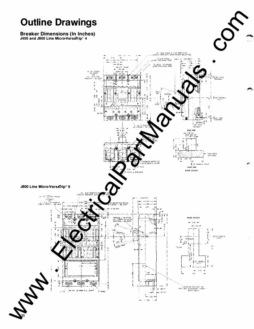
Outline Drawings Breaker Dimensions { In Inches) J400 and J600 Line Micro-VersaTrip" 4
14) 221 HOLES 318 DEED
OR 14) 8--32 TAP INSERTS -� 28 o
_�EP·-'I!ct��:<il!JF=�"��===ot:::�#==J'
J600 Line Micro-VersaTrip® 9
HOLES
�
1
�
I-L �
36
(41 6-32 INSERTS FOR MINE DUTY
CI�CUIT BREAKER OUST COVER MOUNTING
(4) 31 HOLES 50 C BORE- 301 DEEP
(:_ OF POLE & BREAKER '
I I r-- - 394
81TYP
THIS AREA OPTIONAL
392 f- 7 84 -.j
¢ OF HANDLE PIVOT
LOAD END
DOOR CUTOUT
DOOR CUTOUT
------ 2 56 ._j
_.-J 1 28 f-
7 50
"'
1 15
LOCATION FQR EXIT OF TRIP UNIT ACCESSORY WIRES -
BOTH SIDES
• ( OF HANDLE PIVOT
www . El
ectric
alPar
tMan
uals
. com

K800 and K1 200 Line Micro-VersaTrip ' 4
59 OIA
(2) 39 DIA MOUNTING-HOLES (LINE END)
1 1 2 MAX DIA FOR REAR CONNECTION
-'---t/ii;lllt--I_j t M � """'� 1 TE RMINAL me
EXTERNAL GFCT CONN ECTIONS r--t-_j='=J==L_7fc_l (2) -6--32 SCREWS
275 ( OF POLE & BREAKER
�-- �-18 1 ON '
LUG COVER (USED ON LINE & LOAD END)
I I �
TI-t OF HANDLE PIVOT
k '
L��� LUG COVER-r · 38� � KNOCK-OUT -� 75 f--61 DIA
DETAIL OF MOUNTING HOLES
SECTION A-A
� 50--13 TAPPED TERMINALS (LINE AND LOAD ENOl
DOOR CUTOUT
LINE END
LOAD END
FRONT DETAIL
37 www . El
ectric
alPar
tMan
uals
. com

Outline Drawings Breaker Dimensions ( In Inches) K1 200 Line Micro-VersaTrip® 9
� OF POLE & BREAKER (2) LINE END MOUNTING HOLES
(SEE SECTION A-A) / LUG COVERS NOT SUPPLIED 38 1-- WITH CIRCUIT BREAKER
550 1 06 1J 56
tii � � oc Oi§ x � �
r=r,:':���l ('50 I / � �r:�LLU
� � I" --�f»-------({ 8
1 I�; ,�}� Lli R u
i
�
I I ! I $
I � �
59 DIA � ;;;
---
38
. e -' ,-,:'
,><'l If@ � j IW
@ @ , so _f:::=:2.00�
m�� � m: E8
>� .,,_ , , -c 1 56
',._,,,
:��l ,, "'·
,, ;:
@ @ o _ , 90_
__(\_ __{'\_ _df!;: 0 (j) W) (j) �� s (j) (j) ® (j) s
D ID ®
HANDLE 50 THICK 6 TAPER ON EACH SIDE 331
1 rt�11� )' --� I
I \ TRIPPEDJ � / 1 1 850 1 50 �
a: �-::/ --- ��// -r:r: .. s'E:'
v--��b ���M��N,.EL:
�- -- � ' A ,, . ..__ --4��!:-- � , , ,f( �6�N���g �g�ES .,, OF POLE A __I OF POLE
l----21s-+---275-
rr I � � � m
I-- 06- � w
o r c-306� zo :f� � -i-z / 0
'----- � z 0
oc � oc
IL- oc � 0 r
�
� � ri 0 <3
L� � -;:: IT: �
L__
6 i X I :1 [ �-+ ;J;
__j � f-- ss - 1061--
i----J- 1 94
RECOMMENDED FRONT COVER CUT ·OUT
CIRCUIT BREAKER LINE END
OF POLE & BREAKER
J w
'?
�_j_! t;��-� C'BOAE --I 25
SECTION A-A DETAIL OF LOAD & LINE END MOUNTING HOLES.
www . El
ectric
alPar
tMan
uals
. com

Guide Form Specifications
M i cro-Ve rsaTri p® Ci rcu it B reakers 1 50- 1 200 Amperes, 600V ac
The basic ci rcu it breaker must be trip free, offer a qu ick-make, qu ick-break mechanism, have a trip ind icat ing handle position and
push to trip button on the cover of the breaker.
The breaker should be 3 pole, 600 Volts ac with 400, 600, 800 and 1 200 ampere
Table 39.1-lnte r rup ting Ratings in Thousands
The sol id state circuit breaker shal l be General
Br ea ker T yp e 240V ac
TJ 42 THJ 65 TK 42 THK 65
Programmers should be conformal epoxy coated and incorporate gold p lated surfaces on a l l e lectrical connectors and adjustments to assure long last ing and positive electrical contact.
Eight position rotary switches shal l be offered with adjustable cu rrent, adj ustable short t ime pickup, adjustable i nstantaneous and adjustable g round fault pickup sett ings for maxi mum versat i l ity. Four long time delay bands should be avai lable with adjustable long-ti me delay . 12t ramp functions sha l l be avai lable on short t ime and ground fault.
I nternal ly mou nted accessories consisting of shunt tr ip, u nder-voltage release, bell a larm, auxi l iary switches, b lown fuse tr ip and combination accessories of auxi l iary switches and short trips or UVR devices must be avai lable. Drawout mechan isms,
E lectric type Micro-VersaTrip with i nterrupti ng rat ings of:
480V a c 600V a c
30 22 35 25 30 22 50 25
NEMA 1 , 3R, 1 2 and 4/5 enclosures, back connected studs, p lug in mount ing bases, motor operated mechanisms and handle mechanisms (TDF, TDM and TDR) shal l be su itable for use with the M i cro-VersaTrip breakers.
A fu l l function test kit al lowing a test of the prog rammer t ime cu rrent characteristics, f lux sh ift shunt tr ip and conti nu ity of the breaker cu rrent sensor package shall be avai lable.
frames avai lable. Specific sensor ampere ratings shal l be 1 50, 200, 300, 400, 500, 600, 800, 1 000 or 1 200 amperes.
The solid state tr ipping mechanism must offer overload , short circuit and ground fault over current protection with an overload ind icat ion l ight. The breaker and sol id state programmer shal l have ava i lable the following standard and optional programmer funct ions:
"' m "- Q) ell ""' ::J c ell ell - Q) (f) LL
- rn ell Q) c "-0 ::J · - -- ell o._ Q) O LL
9 Function B reaker
• Adjustable Cu rrent Setting
• Long-Time Timing Light • Adjustable Instantaneous
Pickup • Adjustable Long-Time
Delay
• Adjustable Ground Fau lt Pickup and Delay
• Short-Time -Adj ustable Short-Time
Pickup with Short-Time Delay 12t Ramp and Fixed Instantaneous
-Adjustabl e Short-Time Pickup and Delay
-Adjustable Short-Time Pickup and Delay with Fixed Instantaneous
• Adjustable Long-Time Pickup and Short Time 12t Switch
• Zone Selective Interlocking on Short-Time and Ground Fault
• Local and Remote Fault Ind ication Targets on Overload , Short Circu it and Ground Fault
• Remote Long-Time Timing Light
4 F u n ction B reaker
• Adjustable Current Setting
• Long-Time Timing Light • Adjustable Instantaneous
Pickup
• Adjustable Ground Fault P ickup and Delay
• Short Time -Adj ustable Short-Time
Pickup with Short-Time Delay 12t Ramp and Fixed Instantaneous
39 www . El
ectric
alPar
tMan
uals
. com

G e nera l Electric L i terature for P re m i u m Protect ion Desc r i p t i o n N u m be r
Molded Case C i rcuit B reakers
M olded Case C i rcu i t Breakers w i t h M i cro-Versatr ip® G EA 1 0676 Mo lded Case C i rc u i t Breakers-App l i cat ion and Select ion G ET 2779 T H Q E C i rcu it B reakers and Term i n at ions G EA 9755 M ag-Break® Motor C i rc u i t Protectors G EA 7498 M i ne Duty C i rc u i t Breakers G ET 6207
I n s u l ated Case C i rcuit B reakers
Power B reak® I n s u l ated Case C i rc u i t Breakers w i t h M i cro-Versatri p® G EA 1 0677 Power Break® I n s u l ated Case C i rc u i t Breakers - Q u ick Select ion G EA 9752
Low-Voltage Power C i rcuit Breakers
Type AKR Low-Voltage Power C i rc u i t B reakers G EA 1 0667 SST Convers ion K i ts G EA 1 0672 Type AKR Low Voltage Power C i rc u i t B reakers G EA 1 0265
G round Fault P rotective Products
G round Fau l t C i rc u i t I n terru pters G EA 1 0664 G rou nd-Break® Systems G ET 2964
Sa fety Switches
Spec-Setter™ Type TG General Duty Safety Switches Spec-Setter™ Type T H H eavy
G EA 1 0674
Duty Safety Switches Spec-Setter™ M i l l D uty
G EA 1 0675
Safety Switches G EA 9747 Replacement Parts-Spec-Setter™
Safety Switches-Type TG, TH and TC G E F 4452
Disconnect Switches
H C I General Pu rpose D i sconnects G EA 1 0673 Type H PC H i g h Pressure Contact Switches G ET 6205
Outside the U.S. and Canada Write Export Sales and Trad ing Division, 570 Lexington Avenue, New York, N Y 1 0022
G EA 1 06 76A 9/81 PA-J
Descri pt ion N u m be r
C i rcuit B reaker Load Centers
PowerM ark + ® C i rc u i t Breaker Load Centers- Thru 600A G EA 7484 PowerM ark + ® R i ser Pane ls , Para l l e l Type G EA 7494 PowerM ark + ® R iser Panels , Ser ies Type G IZ 2362-1 7 Replacement Parts- C i rc u i t Breaker Load Centers, Modu lar Meteri ng GEF 4453
B usway
Types FVK- FVA 225- 1 000A G EA 6470 A rmor-Clad® 225-5000A G EA 7946 Type CL C u rrent L i m i t i ng G EA 1 0257 Type DH 1 00A G EA 7943 Type LW 30/60A G EA 6743
Panelboards
Types N LTQ/ N LA B G EA 6737 Types N A B/N H B G EA 6738 Type CCB G EA 6739 Type Q M R Fus ib le G EA 6740
Switch boa rds
AV-LI N E® Switch boards G EA 7931 Automatic T h rowover Eq u i pment G EA 1 0261 AV- LI N E® I nsta l l at ion I nstruct ions G EH 2621 Power-Break® I n stal l at i on I nstruct ions G EH 2638 Power- Break® D raw Out Assembly 3000-4000A G EH 2639 Power- Break® Switch boards G EA 1 0258
Switchgea r
Type A KD-6 Low-Voltage Switchgear and Load Center U n i t S u bstat i o n s G EA 1 0279 Type AKD-6 I nsta l l at i on I nstruct ions G EK 72 1 01 Type AKD-8 Low-Voltage Switchgear G EA 1 0264
For further information call or write your local General Electric
Distribution Equipment Division
Sales Office or . . . 41 Woodford Avenue Plainvil le, CT 06062
G E N E R A L 8 E L E C T R I C
·�
0
�
!fl"'
www . El
ectric
alPar
tMan
uals
. com