- frend tm system catalogue number: f10 website : e-mail : [email protected] user manual
TRANSCRIPT

-
FRENDTM SystemCatalogue Number: F10
Website : www.nanoentek.comE-mail : [email protected]
User Manual

2
This manual is considered a necessary part of the equipment: It must be available for the operator to use at the bench as well as for the individual responsible for instrument maintenance.
Read Me First
Thank you for purchasing the FRENDTM System.
Please take a few minutes to read this User Manual.
If you have any questions at any time, please contact NanoEnTek Inc. Technical Support.
Tel: +82-2-6220-7940 Fax: +82-2-6220-7721 E-mail: [email protected]

Maintenance Operation
3
Table of Contents
Setup
Read Me First 2
Table of Contents 3
Warranty 4
Introduction 5
Intended Use 6
Packaging List 7
Symbols and Abbreviations
8
Safety Precautions 9
General Safety Warnings 10-11
FRENDTM System Description
12
Function of the Code Chip and Cartridges
13
Software Keys 14-16
FRENDTM System Setup Procedure
17-21FRENDTM System Operating Procedure
22-25
FRENDTM System Data Management
26-27
FRENDTM System Maintenance
28--31
Cleaning and Storage 32
Troubleshooting 33-38
General Specification-Normal Environmental Conditions
39
Customer Support Information and Version
40
Introduction
Ope
ration
Maintenanc
eS
etup
Introduction

Introduction
Warranty
NanoEnTek Inc. warranties the original purchaser for one(1) year from the date of its initial purchase that this equipment and other devices sold by one of its authorized representatives will function as specified. NanoEnTek Inc. and its representatives shall be relieved of any liability under this warranty if the product is not used in accordance with the manufacturer’s instructions, altered in any way not specified by NanoEnTek Inc., not regularly maintained, used with equipment not approved by NanoEnTek Inc. or used for purposes for which it was not designed.
This warranty does not apply to damages incurred during the initial shipment of the instrument and associated auxiliary materials. Any damages incurred on initial shipment are to be reported immediately to the freight carrier for the settlement of the claim. Please examine the equipment carefully for any damage before signing for the shipment since your signature indicates receipt of undamaged equipment. NanoEnTek Inc. will not be responsible for any indirect, incidental, special, consequential or punitive damages or other losses, including, but not limited to, damages to or losses of other properties or equipment. NanoEnTek will not be responsible for personal injuries, whether to the purchaser or others.
4

The Principle of the FRENDTM System
The principle of the fluorescence detection and calculation of the analyte concentration(drawing from the manual).
Introduction
Introduction
• The FRENDTM System is a portable, automated FRENDTM cartridge reader.
• The FRENDTM System is based on quantitative immunoassay technology capable of quantifying single or multiple analytes by measuring laser-induced fluorescence in a single-use disposable reagent cartridge.
• The FRENDTM cartridge utilizes micro-fluidics lateral flow technology where the analyte of interest in the sample forms immune complexes while moving through the fluidics pathway in the cartridge.
• The concentration of the analyte of interest in an unknown sample is calculated using the ratio of the fluorescent intensity of the Test Zone and the Reference Zone.
5

6
Introduction
Intended Use
The FREND™ System is designed to accommodate the FREND™ cartridge in which a
quantitative in vitro measurement of specific antigens in human serum or plasma are made to
be used as an aid in the clinical management of patients.

7
Adaptor/Power Cable QC Case QC Cartridge QC Code Chip
User Manual Quick Manual Mobile PrinterPipettor
Main Body
Introduction
Package List
When the FREND™ System is received, open the shipping box and carefully check the package contents. Note that the QC designation is used in terms of hardware verification of performance not quality control of the actual testing process for any analytes. Note also that the mobile printer is included only if it was specifically ordered.
USB
FR
EN
D
US
B
OptionalOptionalOptionalOptional

8
Introduction
Safety symbols & Abbreviations
The following symbols are found on the FREND™ System and in the manual and package inserts. Study the meanings of the symbols and always use the equipment in a safe manner.
Symbol Definition Symbol Definition
Warning or CautionAuthorized representative
in the European Community
BIOHAZARD Batch code/lot number
Class I laser product In vitro diagnostic medical device
Manufacturer Reference number/Catalogue number
Disposal of your old appliance1. When this crossed-out wheeled bin symbol is attached to a product it means the product is covered by the European Directive 2012/19/EU.2. All electrical and electronic products should be disposed of separately from the municipal waste stream via designated collection facilities appointed by the government or the local authorities.3. The correct disposal of your old appliance will help prevent potential negative consequences for the environment and human health.4. For more detailed information about disposal of your old appliance, please contact local distributor, waste disposal service or call the number listed in the manual.
IVD
LOT
EC REP

9
Introduction
Safety Precautions
Thoroughly read all instructions before attempting to operate this equipment. Pay particular attention to all safety precautions. The following guidelines must be observed during every phase of operation. Breaking these rules may be dangerous, illegal or affect performance of the equipment and/or invalidate the equipment approval and/or warranty. In order to avoid instrument damage or personal harm, read this manual carefully and follow the instructions given.
• Always ensure that the power supply input voltage matches the voltage available in your location.
• This machine is air-cooled so its surface becomes warm during operation. When installing the equipment on
the countertop always leave a space of more than 10 cm (4 inches) around the instrument in all directions.
• Leave adequate distance between the back of the instrument and the wall to allow the operation of the ‘on’
and ‘off’ power switch. This location must also be accessible to load the QC Code Chip and the test code chips.
• Do not insert metallic objects into the FREND™ System as this could result in an electrical shock, personal
injury and equipment damage. Insert only qualified and authorized devices supplied by NanoEnTek Inc.
• Do not insert any foreign materials into the air vent or the speaker.
• Always set the main switch to the ‘off’ position before connecting the power cord to the wall outlet.
• When unplugging the power cord, be certain to turn the main switch off, then unplug the power cord.
■ NOTE : This equipment has been tested and found to comply with the limits for a Class A digital device, pursuant to part 15 of the FCC rules. These limits are designed to provide reasonable protection against harmful interference when the equipment is operated in a commercial environment. This equipment generates, uses, and can radiate radio frequency energy and, if not installed and used in accordance with the instruction manual, may cause harmful interference to radio communications. Operation of this equipment in a residential area is likely to cause harmful interference in which case the user will be required to correct the interference at his own expense.

• Before using the equipment, read this manual and be certain you thoroughly understand it’s contents.
• Please follow the instructions in this manual to assure proper operation of the equipment.
• When not in use, unplug the equipment from the electrical outlet.
• Perform regular maintenance checks on the main body of the instrument. Inspect all components.
• After long term storage, take extra care to be sure the equipment operates correctly.
• Avoid handling or storing liquid on or near the equipment.
• Do not open the machine at any time while it is operating or when it is plugged in to the wall outlet.
• Keep the instrument away from open flames and or smoke.
• When moving the equipment, unplug it and move it carefully and gently..
• The instrument should be placed on a flat and stable surface.
• Refer to this manual for handling and/or maintenance.
• Keep the equipment (including the cable and the plug) out of reach of children.
• Disposal management
• Local regulations governing the disposal of materials containing biohazardous materials must be
observed. It is in the responsibility of the user to arrange for the proper disposal of these items.
• All instrument parts which may be contaminated with potentially infectious materials must be
disinfected by suitable validated procedures (autoclaving, chemical treatment) prior to disposal if this
is required by the regulations under which your site operates..
• The equipment itself and the electronic accessories must be disposed of according to the
regulations for the disposal of electronic components. Be sure to understand what the rules at your
site are.
10
Introduction
General Safety Warnings

11
Introduction
General Safety Warnings
• Do not attempt to disassemble/modify the equipment.
• Do not insert foreign objects into the equipment and insert only NanoEnTek Inc.-provided cartridges.
• Do not handle the equipment or the power cord with wet hands.
• Do not move, tilt, jar or shake the equipment when it is in operation.
• Do not store the equipment in direct sunlight, high/low temperatures or high humidity.
• Do not throw, drop, hit or push the equipment.
• Do not touch the equipment or the plug during an active thunder and/or lightning storm.
• Do not touch the LCD panel with sharp objects.
• Do not use the equipment, if it has any damaged parts (including the power cord or the plug).
BIOHAZARD
• The cartridge should be inserted into the equipment within the stipulated time .
• The instrument should be used in a clean environment.
• Ensure the sample is not contaminated by any foreign material or contain fibrin clots..
• Human samples and controls should be considered potentially infectious.
• There is a risk of explosion, if the instrument battery is replaced with an incorrect type.
• Class A equipment is intended for use in an industrial environment. In the documentation
for the user, a statement shall be included drawing attention to the fact that there may be
potential difficulties in ensuring electromagnetic compatibility in other environments, due to
conducted as well as radiated electromagnetic disturbances from the instrument itself.
Warning

12
No. Name Function
1 Cartridge Slot Location to insert or remove the FREND™ cartridge
2 Screen Show the operating status and results
3 Ventilation Pathway to dissipate internal heat to the outside
4 Speaker Operational instructions and warning indicators
5 Power Switch Power On/Off
6 Power Supply Port Power Supply
7 USB H Use to connect to a USB memory card.
8 USB D Use to connect to a PC. (manufacturer or supplier only)
9 Code Chip Slot Location for the Insertion of QC or Cartridge Code Chip
10 Serial Port Connection for an optional Mobile Printer
1 2
5 6 7 8 9 10
3 4
Introduction
FRENDTM System

Product Definition
QC Code Chip The chip containing information for the proper functioning of the QC Cartridge.
QC Cartridge The cartridge used to check the mechanics and optics of the FREND™ System
13
Introduction
The Function of the Code Chip and Associated Cartridge
Product Definition
Analyte Code ChipThe Cartridge Code Chip is specific for a given analyte and lot of reagent. It contains information on calibration and calculation of results using readings from the FRENDTM reagent cartridge.
Analyte Cartridge
The cartridge contains reagents and microstructures to support a lateral flow assay, where analytes of interest form immune complexes while the specimen is moving and being separated. Ratio between Test Zone and Reference Zone is calculated.

Button Designation Purpose
TEST Initiates a test sequence for an analyte using that analyte-specific cartridge.
DATA Check and search results. Back up the data and transfer the data to a USB drive.
SETUP Set up the FREND™ System parameters specific for the site and operator.
14
Introduction
Buttons
Main Screen

Button Purpose Button Purpose
Allows user to check the information on the QC or the Cartridge Code Chip.
Allows for software updates.
Allows the user to check the Serial Number, software or Firmware version, and the production date of the instrument.
Location to adjust the time and date for the FRENDTM System.
Allows the user to check the cartridge ID and its associated lot number.
Allows entry of the user name.
Move to the main screen. (HOME)
15
Introduction
Buttons
Setup Screen

Button Purpose Button Purpose
Enter the file name to later identify the data. Backup all the saved data to the connected USB.
Search files or data Delete all the saved data (confirmation required)
View the information of the selected file or data Delete one selected piece of data.
Print the detailed data, using the optional printer if it is connected to the system.
Select data by moving one location at a time..
Backup a selected set of data to the connected USB.
Select data by moving one page at a time.
Home button. Move to the Main Screen. Display the selected data.
16
Introduction
Buttons
Data Screen

17
Setup
FRENDTM System Setup Procedure
No. Picture Action To Be Taken Information
1Carefully examine the box for damage. Remove all components of the FRENDTM System from the box.
2 Plug the power cord into the adaptor.
3
Carefully examine the adaptor and make certain it is compatible with the power at the plug location. If it is the appropriate adaptor, plug the adaptor into the FRENDTM System and the AC power cord into the wall socket.
Warning: If you use an incorrect adaptor, the FRENDTM System may explode or start to burn. If this happens, it will no longer work properly anymore.
4 Turn the power switch to the ON position..
5 While the system is booting up, this image will appear.
6 Check the main screen.
Power Switch

No. Picture Action To Be Taken Information
7 Press the SETUP button on the Main Screen.
8 Press the Date & Time button on the Setup Screen.
9 Set the local date and time.
10After setting the date and time, press the OK button to return to the Setup Screen.
11 Press the User button on the Setup Screen.
12Enter the name of the hospital or office and press the Enter button. When the save is complete, it will automatically move to the Setup Screen.
18
Setup
FRENDTM System Setup Procedure
No. Picture Action To Be Taken Information
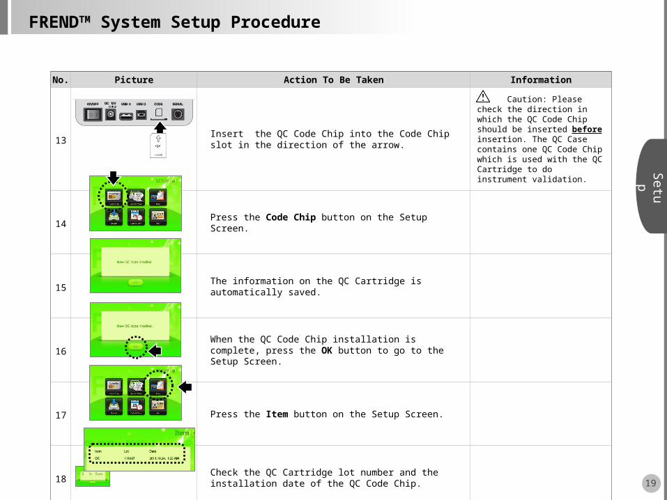
13Insert the QC Code Chip into the Code Chip slot in the direction of the arrow.
Caution: Please check the direction in which the QC Code Chip should be inserted before insertion. The QC Case contains one QC Code Chip which is used with the QC Cartridge to do instrument validation.
14 Press the Code Chip button on the Setup Screen.
15 The information on the QC Cartridge is automatically saved.
16When the QC Code Chip installation is complete, press the OK button to go to the Setup Screen.
17 Press the Item button on the Setup Screen.
18Check the QC Cartridge lot number and the installation date of the QC Code Chip.
19
Setup
FRENDTM System Setup Procedure

No. Picture Action To Be Taken Information
19If the QC Code Chip installation is complete, press the OK button to go to the Setup Screen.
20After all settings are done, press the button and move to the Main Screen.
21 Press the Test button on the Main Screen.
22 Insert the QC Cartridge into the Cartridge slot. Caution: Please check the direction of the QC Cartridge before insertion.
23The QC check that the instrument is operating correctly will complete automatically and the QC Cartridge will be expelled. Please wait patiently..
The system automatically checks three steps while readingStep1. Laser Power Step2. Laser AlignmentStep3. Calculate Ratio
24 ?
When the QC check is done, the QC Cartridge automatically emerges and the results from all the three steps are displayed. There will be three Passes, if the system is properly operating.
Caution: If all tests do not PASS, try steps 21-24 again. If the instrument does not pass all three steps, please contact Technical Support via email..
20
Setup
FRENDTM System Setup Procedure

21
Setup
No. Picture Action To Be Taken Information
25 ? Press the button and move to the Main Screen.
26 Remove the QC Cartridge.
27 Remove the QC Code Chip.
Caution: Press the QC code chip into the slot slightly in order to release it and remove the QC code chip from the slot.
28 The FRENDTM System setup is complete!!!
FRENDTM System Setup Procedure

No. Picture Action To Be Taken Information
1 Turn the power switch to the ‘ON’ position..
2 The system will display this screen while the software boots..
3 Check the Main Screen.
4
Insert the analyte and lot specific Cartridge Code Chip provided in the Cartridge box into the Code Chip slot on the rear of the instrument. Be sure to insert in the direction of the arrow.
Caution: Please double check the direction of the Cartridge Code Chip before insertion. Each Cartridge box contains one analyte and lot specific Cartridge Code Chip. The Code Chip works for all Cartridges in the same box.
5 Press the SETUP button on the Main Screen.
6 Press the Code Chip button on the Setup Screen.
22
Ope
ration
FRENDTM System Operating Procedure
Power Switch
PSA

No. Picture Action To Be Taken Information
7 The Information in the Cartridge is automatically saved.
8If the Cartridge Code Chip installation is complete, press the OK button to go to the Setup Screen.
9 Press the Item button on the Setup Screen.
10Check the cartridge lot number and the installation date of the Cartridge Code Chip. If the Cartridge Code Chip installation is complete, press the OK button to go to the Setup Screen.
11 Press the button and move to the Main Screen.
12 Prepare the Cartridge and patient samples.
For patient samples, collect 2-4 mL of blood in a 5 mL tube. Spin the tube in a centrifuge and collect the serum or plasma.
23
Ope
ration
FRENDTM System Operation Procedure
No. Picture Action To Be Taken Information
13
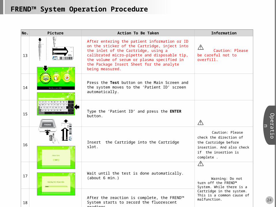
After entering the patient information or ID on the sticker of the Cartridge, inject into the inlet of the Cartridge, using a calibrated micro-pipette and disposable tip, the volume of serum or plasma specified in the Package Insert Sheet for the analyte being measured.
Caution: Please be careful not to overfill.
14Press the Test button on the Main Screen and the system moves to the ‘Patient ID’ screen automatically.
15 Type the ‘Patient ID’ and press the ENTER button.
16 Insert the Cartridge into the Cartridge slot.
Caution: Please check the
direction of the Cartridge before
insertion. And also check if the
insertion is complete .
17 Wait until the test is done automatically. (about 6 min.)
Warning: Do not turn off the FREND™ System. While there is a Cartridge in the system. This is a common cause of malfunction.
18After the reaction is complete, the FRENDTM System starts to record the fluorescent readings.
24
Ope
ration
FRENDTM System Operation Procedure

No. Picture Action To Be Taken Information
19When the test is done, the Cartridge is expelled and the results are displayed.
20If the FRENDTM System is connected to an optional printer, press the Print button and the results will be printed out.
Printers are optional and if
needed should be purchased
separately.
21 The test is complete. If another sample is to be run, repeat again steps 12-19.
The results are stored automatically. If the DATA button on the main screen is pressed, more information is visible..
25
Ope
ration
FRENDTM System Operation Procedure

Type Picture Action To Be Taken Information
Data Selection
Click the direction of the arrow button on the right to select the data. ( moving one file moving one page).The selected data is indicated by the arrow on the left side.
Search
If you click the search box on the top left, it will be switched into the input window.
Click the Enter button after entering the Patient ID on the input window.
Once the input is complete, it will return to the DATA screen. Click the Search button in the top center of the DATA screen to complete the search.
Result Confirmation
After selecting the data, click the Result button to check the results.
PrintIf the printer is connected, click the Print button to print the result. If you click the List button, it will return to the DATA screen.
Printers should be
purchased separately.
26
Ope
ration
Press the DATA button on the Main Screen to check, search, delete the test data, and perform data backup.
FRENDTM System Data Management

Type Picture Action To Be Taken Information
DataBackup
Connect the USB that will receive the data backup to a USB H port on the back of the device.
Caution: Confirm the USB version(1.1). Other formats will not work.
If you want to receive the backup only for a selected data, click the green Select button in the center after selecting the data.
If you want to receive the backup for all of the data, click the green All button in the upper center.
Data Deletion
If you want to delete only a selected data, click the black Select button after selecting the data and the selected data will be deleted.
If you want to delete all of the data, click the black All button and all of the data will be deleted.
27
Ope
ration
Click DATA buttons on the Main Screen to check, search, delete the test data, and perform your backup.
FRENDTM System Data Management
FR
EN
DU
SB

28
To assure reliable and accurate test results, please check the following:
• Observe the external appearance and screen of the FREND™ System every time you use the device. • Check the signal input part of the FREND™ System once a month regardless of the device use, using the QC Cartridge and the QC code chip to specifically test the optics. • If there are any problems found in the results after the checkup, stop using the device immediately and contact the supplier’s Technical Support.
QC Case QC Cartridge QC Code Chip
1. Laser Power
2. Laser Alignment
3. Calculate Ratio
Maintenanc
eFRENDTM System Maintenance
The FREND™ System Checks
The FREND™ System Checklist
The FREND™ System Maintenance Supplies

No. Picture Action To Be Taken Information
1 Turn the power switch to the ‘ON” position.
2Insert the QC Code Chip into the Code Chip slot in the direction of the arrow.
Caution: Please check the
direction of the code chip before
insertion. The QC Case contains
one QC code chip. The QC code
chip works with QC Cartridges
3Check the Main Screen and press the Setup button on Main Screen.
4 Press the Code Chip button on the Setup Screen.
5 The Information on the QC Cartridge is automatically saved.
6When the QC Code Chip installation is complete, press the OK button to go to the Setup Screen.
29
Maintenanc
eFRENDTM System Maintenance
Power Switch

No. Picture Action To Be Taken Information
7 Press the Item button on the setup screen.
8Check the QC Cartridge lot number and the installation date of the QC Code Chip.
9If the QC Code Chip installation is complete, press the OK button to go to the Setup Screen.
10After all settings are edited, press the button and move to the Main Screen.
11 Press the Test button on the Main Screen.
12 Insert the QC Cartridge into the Cartridge slot. Caution: Please check the direction of the QC Cartridge before insertion.
30
Maintenanc
eFRENDTM System Maintenance

No. Picture Action To Be Taken Information
13 Wait until the test is done automatically.
The system automatically checks three steps while readingStep1. Laser Power Step2. Laser AlignmentStep3. Calculate Ratio
14When the test is done, the QC Cartridge is ejected and the results from each of the three steps are displayed.You will see three Passes, if the system is properly operating.
Caution: If you do not pass all tests, try again (11-14). But if you do not pass again, please contact the Technical Support.
15 Press button and move to the Main Screen.
16 Remove the QC Cartridge.
17 Remove the QC Code Chip. Caution: Press the QC code chip first to remove the QC code chip.
18 The FREND™ System check is complete!!!
31
Maintenanc
eFRENDTM System Maintenance

32
Maintenanc
eCleaning and Storage
• Do not clean the FRENDTM System with strong or caustic cleansing agents, chemicals or cleansing tissues
impregnated with chemicals.
• Use a soft and dry cloth to clean the FRENDTM System.
• For safety reasons, disconnect the power supply from the main outlet and remove the power adapter
equipment from the FRENDTM System.
• If you want to store for a lengthy period, keep the FRENDTM System covered in a dry place.
• Do not expose the equipment to direct sunlight.
• Recommended storage conditions are as follows:
- Temperature: 15 ~ 30℃ ℃
- Humidity: 10% ~ 80%
• Store the equipment on a stable surface. Avoid inclination, vibration and impact.
• Do not place the equipment near chemicals and/or corrosive substances.
• Keep the equipment, cable and other accessories well-organized.
• Keep the equipment clean for the next use.
• To move the equipment, carefully pick it up and put it down gently to avoid impact.
• Do not place heavy materials on top of the equipment.
• Wrap or cover the equipment when in storage to protect from dust..

33
Type Error code Error message Possible Cause Possible Solution
CartridgeInsertion Issues
EMCI-01 The Cartridge is not inserted or not inserted correctly.
Re-insert the Cartridge correctly.After insertion, check to make sure the Cartridge is properly and completely inserted.
EMCI-02The Cartridge is not inserted correctly.
Re-insert the Cartridge correctly.After insertion, check to make sure the Cartridge is properly and completely inserted.
EMCI-03The Cartridge is not inserted correctly.
Re-insert the Cartridge correctly.After insertion, check to make sure the Cartridge is properly and completely inserted.
EMCI-04The direction of the inserted Cartridge is not correct.
Re-insert the Cartridge correctly.After insertion, check to make sure the Cartridge is properly and completely inserted.
Maintenanc
eTroubleshooting
If the FRENDTM System malfunctions, please check the following before you contact Customer Support.

Type Error code Error message Possible Cause Possible Solution
Barcode Issues
EMBR-01
The barcode printed on the Cartridge may have been damaged so the reader is unable to interpret the code correctly.
Remove the damaged Cartridge from the system. Load a new Cartridge with sample and reinsert the Cartridge into the Cartridge slot. Discard the damaged Cartridge.
EMBR-02
The barcode information related to the Cartridge lot number printed on the Cartridge is not readable by the system reader.
Manually enter the lot number of the Cartridge using the keypad. The lot number is printed directly above the barcode on the Cartridge.
EMBR-03
The lot number entered for the Cartridge does not match the lot number on the Code Chip.
Carefully enter the lot number of the Cartridge again. If the same message is repeated, check the lot number on the installed Code Chip. If Code Chip and Cartridge lots do not match, change either Code Chip or Cartridge so they are the same lot number and retry loading the Cartridge.
34
Maintenanc
eTroubleshooting
If the FRENDTM System malfunctions, please check the following before you contact Customer Support.

Type Error code Error message Possible Cause Possible Solution
Data Backup Issues
EMDB-01
The USB version is not correct, the USB drive is not properly connected to the FRENDTM System or the USB drive or USB H port has somehow been damaged..
Check to be sure the USB drive is the version 1.1 required for the FRENDTM System and that the USB is connected properly to the USB H port. If after trying a second time with the same USB drive the error message is repeated, try a new USB drive version 1.1. If the problem persists, contact Customer Support for assistance.
EMDB-02
A problem has been detected when attempting to transfer data from the FRENDTM System to the USB drive.
Check to be sure the USB drive is the version 1.1 required for the FRENDTM system and that the USB is connected properly to the USB H port. If after trying a second time with the same USB drive the error message is repeated, try a new USB drive version 1.1. If the problem persists, contact Customer Support for assistance.
Data Save
Issues
EMDS-01
The storage capacity of the FRENDTM System to store the data has been exceeded.
Back up the data stored in the FRENDTM System to a version 1.1 USB. Then, delete the data stored in the FRENDTM System so space is again available on the system.
35
Maintenanc
eTroubleshooting
If the FRENDTM System malfunctions, please check the following before you contact Customer Support.

Type Error code Error message Possible Cause Possible Solution
Code Chip Install Issues
EMCC-01
The Code Chip is not inserted properly, the Code Chip has somehow been damaged or the FRENDTM
System does not recognize the Code Chip.
Check that the Code Chip is installed properly. If it appears to be properly installed, remove the Code Chip from the system, locate another Code Chip from the same lot number and restart the Code Chip installation process.If the problem continues, contact Customer Support.
EMCC-02
The FRENDTM System does not recognize the Code Chip.
Restart the Code Chip installation process. If the problem persists, locate another Code Chip from the same lot number and restart the Code Chip installation process.If the problem continues, contact Customer Support.
TestResult
Issues
EMTF-01
The lot number of the inserted Cartridge is different from the lot number of the installed Code Chip.
Check that the lot number printed on the Cartridge is the same as the lot number on the Code Chip. If not, restart using a Code Chip and Cartridge of the same lot number. If the original set were the same lot number, try a new Code Chip and Cartridge pair in case either was damaged.
EMTF-02
Unable to output a test result because the system detected readings in the Cartridge during analysis that were abnormal so a result could not be calculated.
Load the same sample into a new Cartridge and load the Cartridge into the system. If the problem is repeated, try a sample from a different source (different patient). If the problem continues, contact Customer Support.
36
Maintenanc
eTroubleshooting
If the FRENDTM System malfunctions, please check the following before you contact Customer Support.

Type Error code Error message Possible Cause Possible Solution
Test Result Issues (cont.)
EMTF-03
Unable to output a test result because the system detected readings in the Cartridge during analysis that were abnormal so a result could not be calculated.
Load the same sample into a new Cartridge and load the Cartridge into the system. If the problem is repeated, try a sample from a different source (different patient). If the problem still continues, contact Customer Support.
EMTF-04The lateral flow of the sample within the Cartridge is incomplete.
Load the sample into a new Cartridge and restart the test. If the same error message is displayed, centrifuge the sample to remove particulate matter and fibrin clots and retry with a new Cartridge. If the problem persists, try a different sample. If the problem still continues, contact Customer Support.
EMTF-05The lateral flow of the sample within the Cartridge is incomplete
Load the sample into a new Cartridge and restart the test. If the same error message is displayed, centrifuge the sample to remove particulate matter and fibrin clots and retry with a new Cartridge. If the problem persists, try a different sample. If the problem still continues, contact Customer Support
EMTF-06The lateral flow of the sample within the Cartridge is incomplete
Load the sample into a new Cartridge and restart the test. If the same error message is displayed, centrifuge the sample to remove particulate matter and fibrin clots and retry with a new Cartridge. If the problem persists, try a different sample. If the problem still continues, contact Customer Support
37
Maintenanc
eTroubleshooting
If the FRENDTM System malfunctions, please check the following before you contact Customer Support.
Type Error code Error message Possible Cause Possible Solution
Update Issues
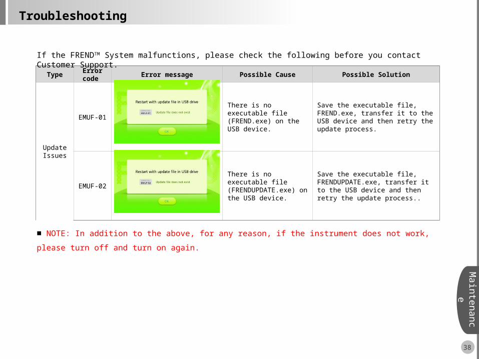
EMUF-01 There is no executable file (FREND.exe) on the USB device.
Save the executable file, FREND.exe, transfer it to the USB device and then retry the update process.
EMUF-02
There is no executable file (FRENDUPDATE.exe) on the USB device.
Save the executable file, FRENDUPDATE.exe, transfer it to the USB device and then retry the update process..
38
Maintenanc
eTroubleshooting
If the FRENDTM System malfunctions, please check the following before you contact Customer Support.
■ NOTE: In addition to the above, for any reason, if the instrument does not work, please turn off and turn on again.

39
Maintenanc
eGeneral Specification-Normal Environmental Conditions
• Electrical rating: Voltage: AC100 ~ 240 V, Current: 1.7 A, Frequency: 50 ~ 60 Hz
• Electric input: Voltage: DC12 V, Current: 3.33 A
• Dimensions: 240 mm x 260 mm x 175 mm (W x L x H)
• Weight: 3 Kg (6.6 lbs)
• Degree of protection: IPX0
• Optical power: Class I
• User interface: Active screen size (7.0 inches diagonal dimension), Pixel format (800 x 480, TFT LCD)
• Mobile printer(Optional): Size: 75 mm x 103 mm x 44.3 mm, Weight: 237 g, Interface: Serial(RS232C),
Print width: 2 inch(48 mm), Printing speed: 50 mm/sec
• Environmental Suggestions for Optimal Performance
• Do not place unit in the direct sun
• Position the unit in a well-ventilated area
• Place the unit on a flat, dry and smooth surface with sufficient ventilation area around the unit
• Operating condition: Temperature: 15 ~ 30 , Humidity: 10% ~ 80% ℃ ℃
• Storage condition: Temperature: 15 ~ 30 , Humidity: 10% ~ 80% ℃ ℃
40
Maintenanc
eCustomer Support Information
All materials in this manual are protected by Korean and International copyright laws. They cannot be reproduced, translated, published or distributed without the permission of the copyright owner.
Every effort has been made to avoid errors in text and diagrams. However, NanoEnTek Inc. assumes no responsibility for any unintentional errors which may appear in this publication. Information and specifications contained in this document are subject to change at any time without prior notice. For the most up-to-date information, contact NanoEnTek, Inc.’s Customer Support.
This product is sold all over the world. Customer Support services vary for each geographical region. When the FRENDTM System is shipped, information will be included that lists the appropriate telephone numbers, fax numbers and email addresses from which support for your geographical region can be most readily obtained.
The information in this manual has been carefully reviewed and has been found to be as accurate. However, it may be changed by the copyright owner without prior consent or notification.
Copyright © 2012, by NanoEnTek Inc. All rights reserved. Published in Korea.
Document Number NESMU-F10-002EN (V.0.2)
Revision History V.0.2 Date: February 12, 2013V.0.1 Date: December 22, 2012 V.0.0 Date: January 16, 2012

43
FRENDTM System
Catalogue Number: F10
User Manual
12F Ace High-End Tower 235-2, Guro3-dong, Guro-gu, Seoul, 152-740, Korea
Tel: +82-2-6220-7940 / Fax: +82-2-6220-7721 / www.nanoentek.com
731-30 Jiwol-ri, Paltan-myeon, Hwaseong-si, Gyeonggi-do, 445-917, Korea
5627 Stoneridge Drive Suite 304, Pleasanton, CA 94588, USATel:+1-925-225-0108, +1-888-988-0108 (Toll free) / Fax:+1-925-225-0109
SK Medical ( Beijing ) Co. , Ltd.2301C SK Tower No.6 Jia, Jianguomenwai Avenue, Chaoyang District, Beijing, 100022 P.R.China Tel : +86-10-5920-7844 / Fax: +86-10-5920-5697
MT Promedt Consulting GmbHAltenhofstrasse 80, 66386 St. Ingbert, Germany
NanoEnTek Inc.
USA
China
Manufactured by
Manufacturing site