« efficiency map of the traction system of an ev from an on-road
TRANSCRIPT
EMR’14CoimbraJune 2014
Summer School EMR’14“Energetic Macroscopic Representation”
«« Efficiency Map of the Traction System Efficiency Map of the Traction System of an EV from an Onof an EV from an On--Road Test DriveRoad Test Drive»»
Clément Dépature1, Dr. Walter Lhomme1, Prof. Alain Bouscayrol1Prof. Pierre Sicard2, Dr. Loïc Boulon2
1 L2EP, Université Lille1, MEGEVH network2 GREI, Université du Québec à Trois-Rivières
EMR’14, Coimbra, June 20142
«« Efficiency Map of an EV Efficiency Map of an EV traction system traction system »»
- Outline -
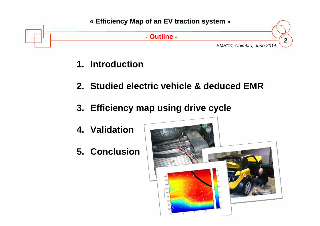
1. Introduction
2. Studied electric vehicle & deduced EMR
3. Efficiency map using drive cycle
4. Validation
5. Conclusion

EMR’14CoimbraJune 2014
Summer School EMR’14“Energetic Macroscopic Representation”
«« INTRODUCTION INTRODUCTION »»
EMR’14, Coimbra, June 20144
«« Efficiency Map of an EV Efficiency Map of an EV traction system traction system »»
- I. Introduction -
Real system
Control
Strategy
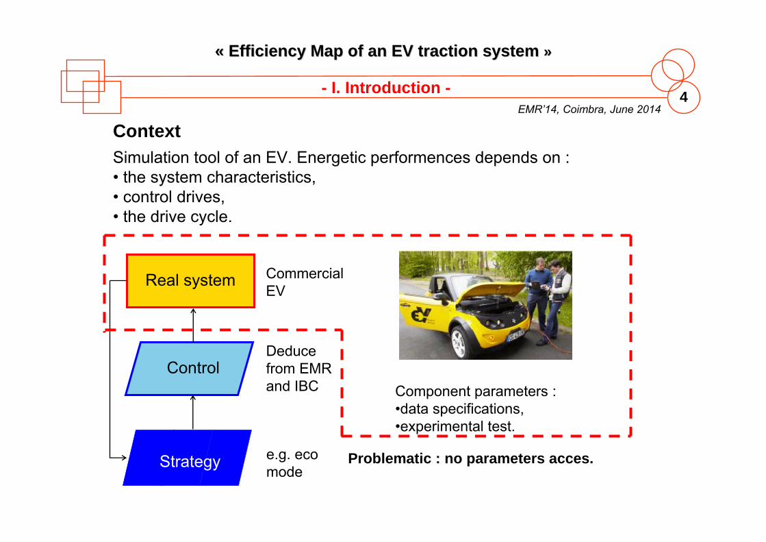
Simulation tool of an EV. Energetic performences depends on :• the system characteristics, • control drives, • the drive cycle.
Deducefrom EMR and IBC
e.g. ecomode
Commercial EV
Component parameters :•data specifications, •experimental test.
Problematic : no parameters acces.
Context
EMR’14, Coimbra, June 20145
«« Efficiency Map of an EV Efficiency Map of an EV traction system traction system »»
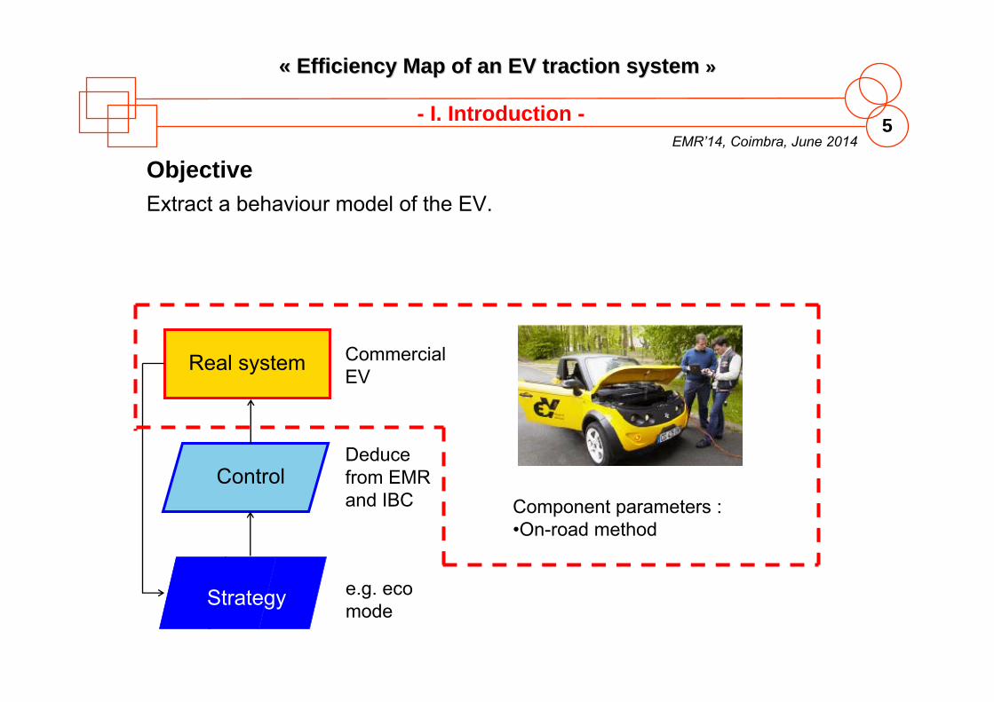
Objective
Real system
Control
Strategy
Deducefrom EMR and IBC
e.g. ecomode
Commercial EV
Component parameters :•On-road method
Extract a behaviour model of the EV.
- I. Introduction -
EMR’14CoimbraJune 2014
Summer School EMR’14“Energetic Macroscopic Representation”
«« STUDIED ELECTRIC VEHICLE & STUDIED ELECTRIC VEHICLE & DEDUCED EMR DEDUCED EMR »»
EMR’14, Coimbra, June 20147
«« Efficiency Map of an EV Efficiency Map of an EV traction system traction system »»
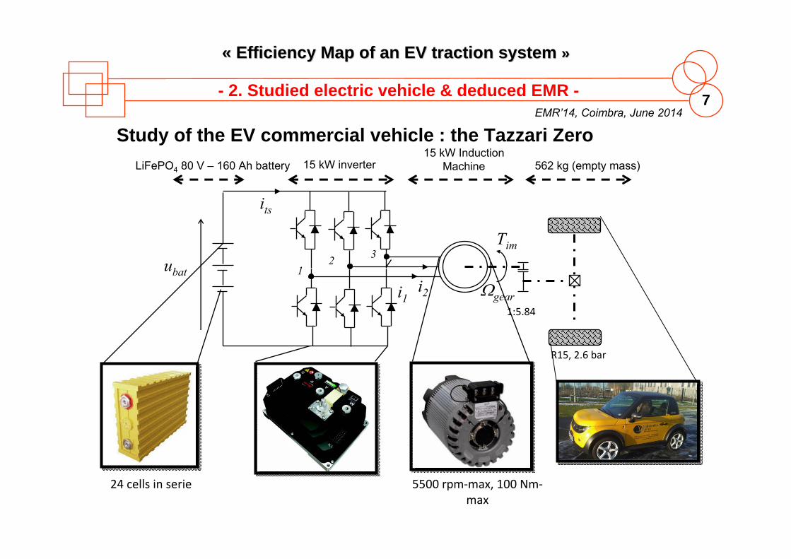
- 2. Studied electric vehicle & deduced EMR -
LiFePO4 80 V – 160 Ah battery 15 kW inverter15 kW Induction
Machine 562 kg (empty mass)
Study of the EV commercial vehicle : the Tazzari Zero
24 cells in serie
R15, 2.6 bar
1:5.84
ubati2
12 3
Tim
geari1
its
5500 rpm‐max, 100 Nm‐max
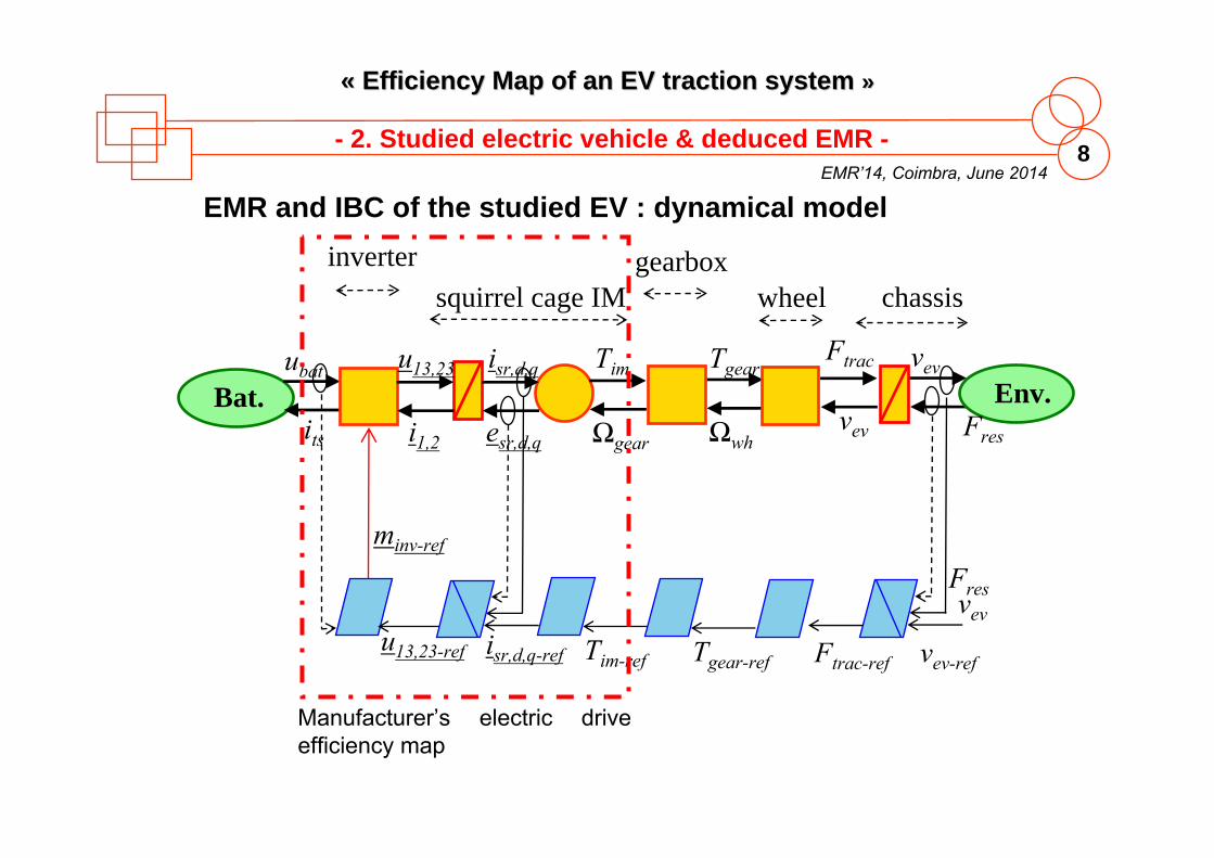
EMR’14, Coimbra, June 20148
«« Efficiency Map of an EV Efficiency Map of an EV traction system traction system »»
Bat.ubat
its
Env.Tim
Ωgear
Ftrac
vev
vev
Fres
minv-ref
vev-refTgear-refTim-ref
Ωwh
vev
Fres
Tgearu13,23
i1,2
isr,d,q
esr,d,q
isr,d,q-ref
squirrel cage IM chassisinverter gearbox
wheel
EMR and IBC of the studied EV : dynamical model
Manufacturer’s electric drive efficiency map
- 2. Studied electric vehicle & deduced EMR -
Ftrac-refu13,23-ref
EMR’14, Coimbra, June 20149
«« Efficiency Map of an EV Efficiency Map of an EV traction system traction system »»
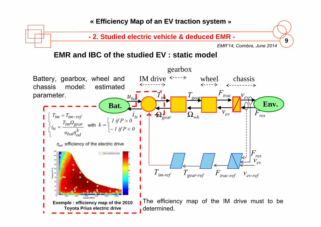
EMR and IBC of the studied EV : static model
Battery, gearbox, wheel and chassis model: estimatedparameter.
kedbat
gearimts
refimim
u
ΩTi
TT
01 if P
0 1 if Pkwith
ηed :efficiency of the electric drive
Exemple : efficiency map of the 2010 Toyota Prius electric drive
The efficiency map of the IM drive must to bedetermined.
Bat.ubat
its
Tim
Ωgear
Tim-ref
IM drivegearbox
- 2. Studied electric vehicle & deduced EMR -
Env.Ftrac
vev
vev
Fres
vev-refTgear-ref
Ωwh
vev
Fres
Tgear
chassiswheel
Ftrac-ref
EMR’14, Coimbra, June 201410
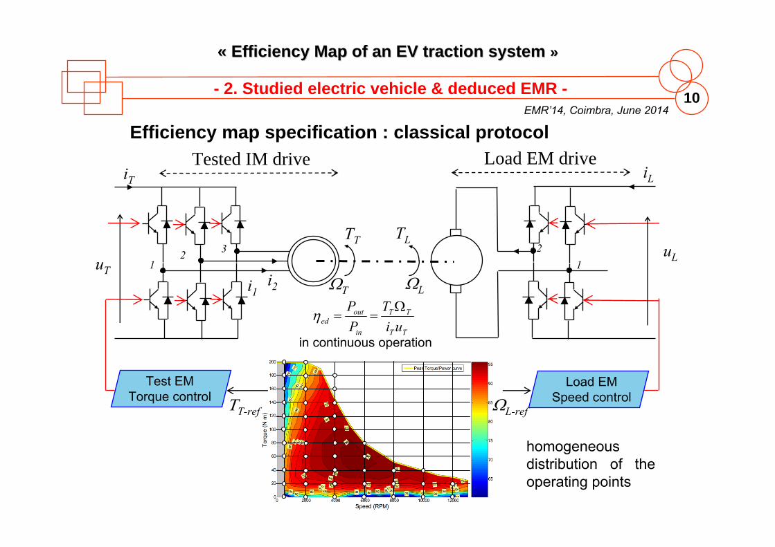
«« Efficiency Map of an EV Efficiency Map of an EV traction system traction system »»
Efficiency map specification : classical protocol
TT
TT
in
outed ui
TPP
in continuous operation
i2
12 3
TT
Ti1
12
TL
L
uT
iT
uL
iLTested IM drive Load EM drive
Test EMTorque control
Load EMSpeed controlL-refT-ref
homogeneous distribution of the operating points
- 2. Studied electric vehicle & deduced EMR -
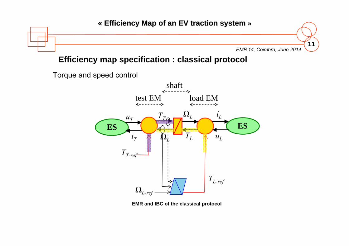
EMR’14, Coimbra, June 201411
«« Efficiency Map of an EV Efficiency Map of an EV traction system traction system »»
ESuT
iT
TT
ΩL
test EM
Efficiency map specification : classical protocol
ES
TT-ref
TL
ΩL-ref
TL-ref
load EMshaft
Torque and speed control
EMR and IBC of the classical protocol
ΩL iL
uL
EMR’14, Coimbra, June 201412
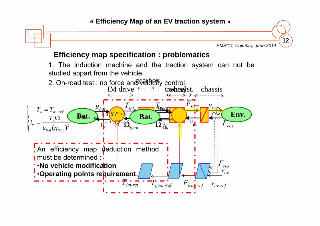
«« Efficiency Map of an EV Efficiency Map of an EV traction system traction system »»
Efficiency map specification : problematics1. The induction machine and the traction system can not bestudied appart from the vehicle.
Bat.ubat
its
Tim
Ωgear
Tim-ref
IM drivegearbox
Env.Ftrac
vev
vev
Fres
vev-refTgear-ref
Ωwh
vev
Fres
Tgear
chassiswheel
Ftrac-ref
Bat.ubat
its
trac. syst.2. On-road test : no force and velocity control.
An efficiency map deduction methodmust be determined :•No vehicle modification•Operating points requirement
ktracbat
wwts
refww
uTi
TT
)(with
01 if P
0 1 if Pk
EMR’14CoimbraJune 2014
Summer School EMR’14“Energetic Macroscopic Representation”
«« EFFICIENCY MAP USING EFFICIENCY MAP USING DRIVE CYCLEDRIVE CYCLE»»
EMR’14, Coimbra, June 201414
«« Efficiency Map of an EV Efficiency Map of an EV traction system traction system »»
- 3. Efficiency map using drive cycle -
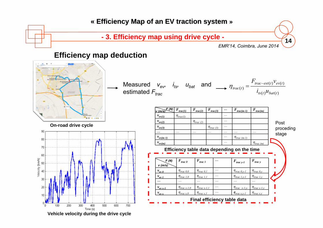
Efficiency map deduction
On-road drive cycle
)()(
)()()(
tbattts
tevtesttracttrac ui
vF
Ftrac(1) Ftrac(2) Ftrac(3)… Ftrac(m-1) Ftrac(m)
vev(1) ηtrac(1)…
vev(2) ηtrac (2)…
vev(3) ηtrac (3)…
… … … … … … …
vev(m-1)… ηtrac (m-1)
vev(m)… ηtrac (m)
Efficiency table data depending on the time
Final efficiency table data
Post procedingstage
Ftrac 0 Ftrac 1… Ftrac y-1 Ftrac y
vev 0 ηtrac 0,0 ηtrac 0,1… ηtrac 0,y-1 ηtrac 0,y
vev 1 ηtrac 1,0 ηtrac 1,1… ηtrac 1,y-1 ηtrac 1,y
… … … … … …
vev x-1 ηtrac x-1,0 ηtrac x-1,1… ηtrac x-1,y-
1
ηtrac x-1,y
vev x ηtrac x,0 ηtrac x,1… ηtrac x,y-1 ηtrac x,y
F (N)v (m/s)
F (N)v (m/s)
Vehicle velocity during the drive cycle
Measured vev, its, ubat and estimated Ftrac
EMR’14, Coimbra, June 201415
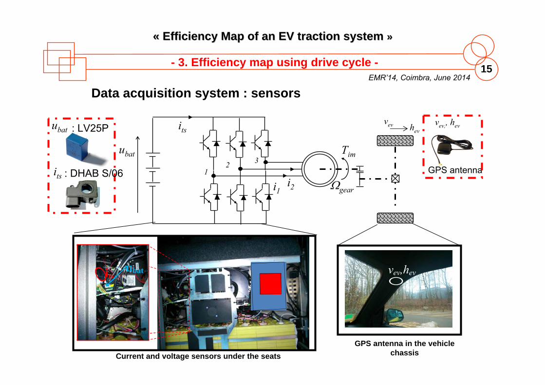
«« Efficiency Map of an EV Efficiency Map of an EV traction system traction system »»
- 3. Efficiency map using drive cycle -
ubat its vev,hev
Data acquisition system : sensors
vev hev: LV25Pubat
its
vev,, hev
GPS antenna
Current and voltage sensors under the seatsGPS antenna in the vehicle
chassis
ubat
i2
12 3
Tim
geari1
its
: DHAB S/06
EMR’14, Coimbra, June 201416
«« Efficiency Map of an EV Efficiency Map of an EV traction system traction system »»
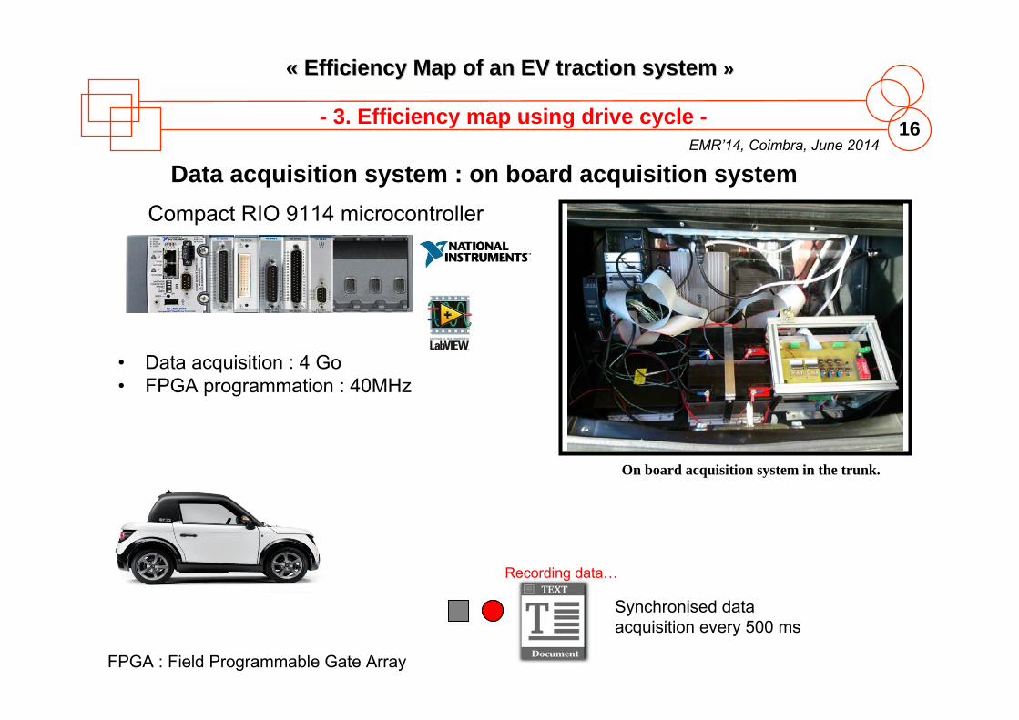
- 3. Efficiency map using drive cycle -
Data acquisition system : on board acquisition system
On board acquisition system in the trunk.
Compact RIO 9114 microcontroller
• Data acquisition : 4 Go • FPGA programmation : 40MHz
FPGA : Field Programmable Gate Array
Recording data…
Synchronised data acquisition every 500 ms
EMR’14, Coimbra, June 201417
«« Efficiency Map of an EV Efficiency Map of an EV traction system traction system »»
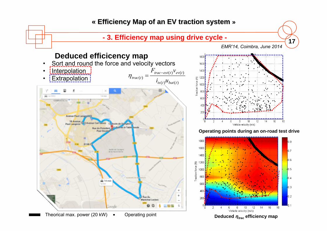
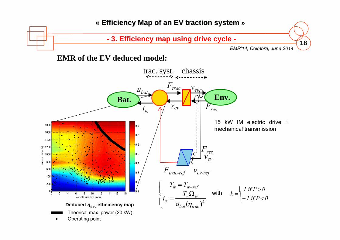
Deduced efficicency map
- 3. Efficiency map using drive cycle -
Theorical max. power (20 kW) Operating point
• Sort and round the force and velocity vectors• Interpolation• Extrapolation
Operating points during an on-road test drive
Deduced ηtrac efficiency map
)()(
)()()(
tbattts
tevtesttracttrac ui
vF
EMR’14, Coimbra, June 201418
«« Efficiency Map of an EV Efficiency Map of an EV traction system traction system »»
EMR of the EV deduced model:
15 kW IM electric drive + mechanical transmission
Deduced ηtrac efficicency mapTheorical max. power (20 kW)Operating point
- 3. Efficiency map using drive cycle -
Env.Ftrac
vev
vev
Fres
vev-ref
vev
Fres
Ftrac-ref
Bat.ubat
its
chassistrac. syst.
ktracbat
wwts
refww
uTi
TT
)(with
01 if P
0 1 if Pk

EMR’14CoimbraJune 2014
Summer School EMR’14“Energetic Macroscopic Representation”
«« Validation Validation »»
EMR’14, Coimbra, June 201420
«« Efficiency Map of an EV Efficiency Map of an EV traction system traction system »»
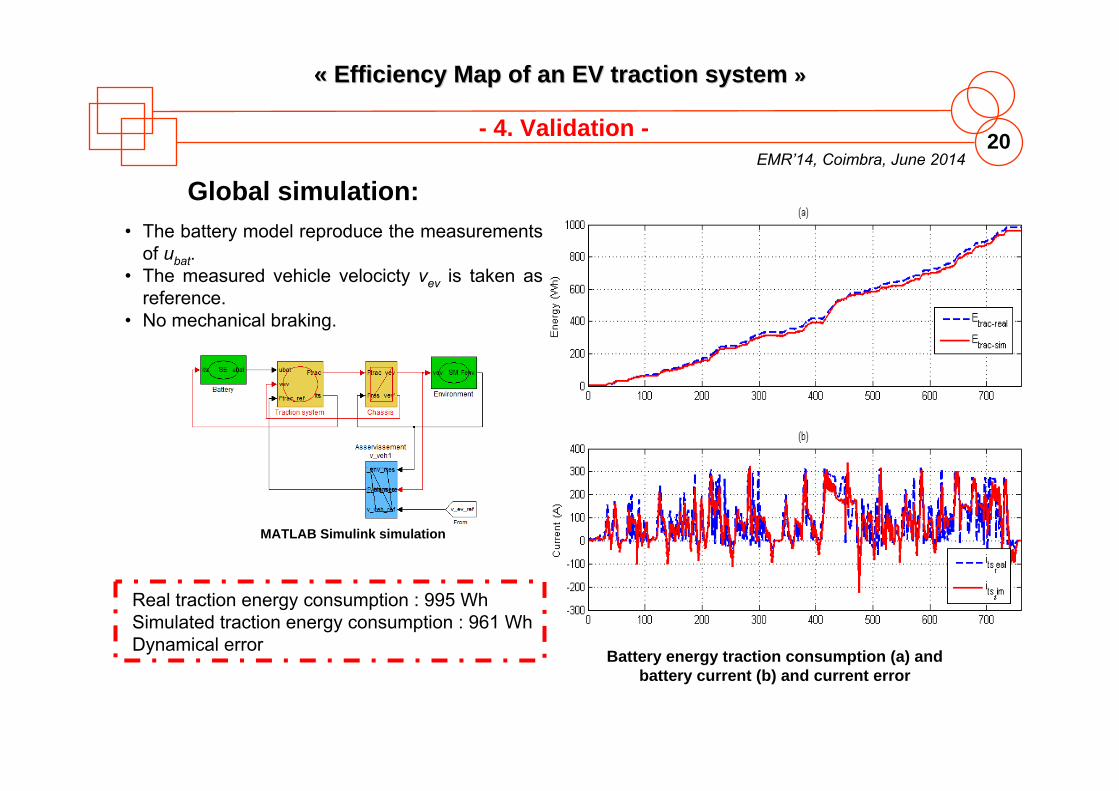
- 4. Validation -
• The battery model reproduce the measurementsof ubat.
• The measured vehicle velocicty vev is taken as reference.
• No mechanical braking.
Global simulation:
MATLAB Simulink simulation
Battery energy traction consumption (a) and battery current (b) and current error
Real traction energy consumption : 995 WhSimulated traction energy consumption : 961 WhDynamical error

EMR’14CoimbraJune 2014
Summer School EMR’14“Energetic Macroscopic Representation”
«« Conclusion Conclusion »»
EMR’14, Coimbra, June 201422
«« Efficiency Map of an EV Efficiency Map of an EV traction system traction system »»
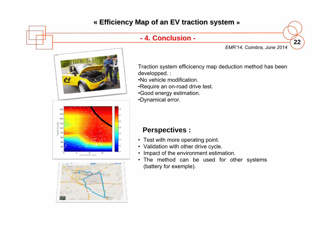
- 4. Conclusion -
Traction system efficicency map deduction method has been developped. :•No vehicle modification.•Require an on-road drive test.•Good energy estimation.•Dynamical error.
Perspectives : • Test with more operating point.• Validation with other drive cycle.• Impact of the environment estimation.• The method can be used for other systems
(battery for exemple).

EMR’14CoimbraJune 2014
Summer School EMR’14“Energetic Macroscopic Representation”
«« BBIOGRAPHIES AND IOGRAPHIES AND RREFERENCES EFERENCES »»
EMR’14, Coimbra, June 201424
«« Efficiency Map of an EV Efficiency Map of an EV traction system traction system »»
- Authors -
Prof. Alain BouscayrolUniversity Lille 1, L2EP, MEGEVH, FranceCoordinator of MEGEVH, French network on HEVsPhD in Electrical Engineering at University of Toulouse (1995)Research topics: EMR, HIL simulation, tractions systems, EVs and HEVs
Clément DépatureUniversity Lille 1, L2EP, MEGEVH, FranceMaster’s degree in Electrical Engineering from University Lille (2011)Research topics: Formalization of control systems , EVs and HEVs
Dr. Walter LhommeUniversity Lille 1, L2EP, MEGEVH, FrancePhD in Electrical Engineering at University Lille1 (2007)Research topics: modelling, control and energy management for hybrid and electric vehicles.
EMR’14, Coimbra, June 201425
«« Efficiency Map of an EV Efficiency Map of an EV traction system traction system »»
- Authors -
Prof. Pierre SicardUniversité du Québec à Trois-Rivières, GREIPhD in Electrical Engineering at Rensselaer Polytechnic Institute (1993)Research topics: Controller and observer design for nonlinear systems,control of power electronics and multidrive systems, adaptive control, and neural networks.
Dr. Loïc BoulonUniversité du Québec à Trois-Rivières, GREI, IRHPhD in Electrical Engineering at University of Franche-Comté (2009)Research topics: hybrid electric vehicles, energy and power sources, and fuel-cell systems.
EMR’14, Coimbra, June 201426
«« Efficiency Map of an EV Efficiency Map of an EV traction system traction system »»
- References -
• Chan, C.C., "The State of the Art of Electric, Hybrid, and Fuel Cell ehicles," Proceedings of the IEEE , vol.95, no.4, pp.704,718, April 2007
• Ehsani, M; Gao, Y.; Gay, S.E.; Emadi, A., “Modern electric, hybrid electric, and fuel cell vehicles: fundamentals, theory, and design.” CRC press, Dec. 2004
• Spichartz, P.; Schael, M.; Ni, B.; Broy, A.; Sourkounis, C., "Fleet test of electric vehicles regarding their suitability for daily use," SPEEDAM’12, June 2012
• Affanni, A.; Bellini, A.; Franceschini, G.; Guglielmi, P.; Tassoni, C., "Battery choice and management for new-generation electric vehicles," IEEE Transactions on Industrial Electronics, vol.52, no.5, pp.1343,1349, Oct. 2005
• Saegesser, I.; Vezzini, A.; Galliker, B., "Cost and power optimized electrical drive train system design for an electric three-wheel vehicle based on field test data acquisition and offline simulations," IEEE-VPPC’11, Chicago (USA)
• Dehlinger, N.; Desjardins, M.; Dubois, M., “Plug-In Hybrid Electric Vehicle (PHEV) Québec Test Program: A Major Real-World Test Study on Financial, Technological and Social Aspects of PHEVs,” EVRE Monaco, 2009.
• Cheng, Y.; Bouscayrol, A.; Trigui, R.; Espanet, C.; Cui, S., “Field weakening control of a PM electric variable transmission for HEV", Journal of Electrical Engineering and Technology, September 2013, vol. 8, no. 5, pp. 1096-1106
• Chen, K.; Bouscayrol, A.; Berthon, A.; Delarue, P.; Hissel, D.; Trigui, R., "Global modeling of different vehicles," IEEE Vehicular Technology Mag., vol.4, no.2, pp.80,89, June 2009
EMR’14, Coimbra, June 201427
«« Efficiency Map of an EV Efficiency Map of an EV traction system traction system »»
• IEEE Guide for Test Procedures for Synchronous Machines Part IAcceptance and Performance Testing Part II Test Procedures and Parameter Determination for Dynamic Analysis - Redline," IEEE Std 115-2009 (Revision of IEEE Std 115-1995) - Redline , vol., no., pp.1,219, May 7 2010
• Tazzari zero web site, http://www.tazzari-zero.com/• Letrouve, T.; et al., "Different models of a traction drive for an electric vehicle
simulation," IEEE-VPPC’10, Lille, Sept. 2010• Bouscayrol, A et al., “Control Structures for Multi-machine Multi-converter Systems with
upstream coupling”, Mathematics and Computers in Simulation, vol. 63, no. 3-5, pp. 261-270, November 2003
• IEEE Standard Test Procedure for Polyphase Induction Motors and Generators," IEEE Std 112-1996 , 1997
• Bin Lu, et al. “A Survey of Efficiency Estimation Methods of In-Service Induction Motors with Considerations of Condition Monitoring Requirements,” IEMDC 2005 May 2005.
• Hofman, T.; Steinbuch, M; Van Druten, R,; Serrarens, A,. ”Design Specifications for Hybrid Vehicles”, 7th International Symposium on Advanced Vehicle Control, Arnhem, 2004
• Memento de Technologie Automobile, 3ème édition, BOSCH• Deprez, W., et al. “Iso Efficiency Contour as a Concept to Characterize Variable Speed Drive
Efficiency,” ICEM 2010, Roma.• Stockman, K., Dereyne, S., Vanhooydonck, D., Symens, W., Lemmens, J., and Deprez, W.,
“Iso efficiency contour measurement results for variable speed drives,” ICEM 2010, Roma.
- References -