cabriolet airbag - dandydanny.org · introduction . a driver's side airbag is now installed as...
TRANSCRIPT

. Cabriolet
Airbag
ce Training •• ¥,~lRrQrmation

Volkswagen of America, Inc. Service Training Printed in U.S.A.
Printed 10/89 Part #WSP 521-205-00
All rights reserved. All information contained in this manual is based on the latest product information available at the time of printing . The right is reserved to make changes at any time without notice. No part of this publication may be reproduced, stored in a retrieval system, or transmitted in any form or by any means, electronic, mechanical, photocopying, recording or otherwise, without prior written permission of the publisher. This includes text, figures and tables .
Always check P-circulars and the microfiche system for information that may supersede any information included in this booklet.

LfIndex
Introduction .......................................................... 1
Airbag System . ..... ... .. ... . .... .. ... .... ... ...... .... ... . ....... . .. . 2
Airbag Operation .. ................. ... . .......... ... ....... ........... 3
Components Location ........................................................... 5 Airbag Unit . . .. ................ ... . .. .. ..... .... ......... . . .. ....... 6 Airbag ............................................................. 7 Gas Generator ...... .. . ....... .. .. . ................. . .. . . ... ........ 8 Spiral Spring ........................................................ 1 0 Front Impact Sensors ......... ......... .. .. .............. . .......... 11 Control Unit .... . . .. ... .... .. ... . .... .... ............ ... . . . . ...... . . 15 Instrument Lights ... .... . ........ .......... .. ................. ...... 17 Knee Bar ~" ... ..... ..... ...... . ......... ..... ................ ....... 18 Windshield' ......................................................... 19 Front Seat Belts .................................................... 20 Steering Wheel ..................................................... 21
VAG 1551 ...... .. . .... .. ....... .. .. ... .. .... . ...... . . ......... . ...... 23
Wiring Diagram ....................................................... 24
Service Cautions ...................................................... 26
• I

Introduction
A driver's side airbag is now installed as standard equipment on the 1990 Volkswagen Cabriolet.
The airbag is a supplementary restraint system designed to work together with the seat belts. However, the airbag allows the Cabriolet to meet the federal passive restraint standard even if the driver is not wearing a seat belt.
The airbag itself is folded up within the steering wheel. The airbag will be activated if the vehicle is in a frontal collision with a force equivalent to striking a solid barrier at a speed of approximately 9 to 12 mph or greater.
Note: The battery must be disconnected for 20 minutes before working on any part of the airbag system.
1
It is not designed to work in all impact situations, such as angular impacts or impacts less than the force described.
The airbag will be inflated within 25 to 30 milliseconds (less than the blink of an eye). The airbag then acts as an air cushion between the driver and the steering wheel to dissipate the energy of the driver's forward movement in a collision .
The airbag can only be inflated once. After it has been inflated, the airbag must be replaced. It cannot be re-used.
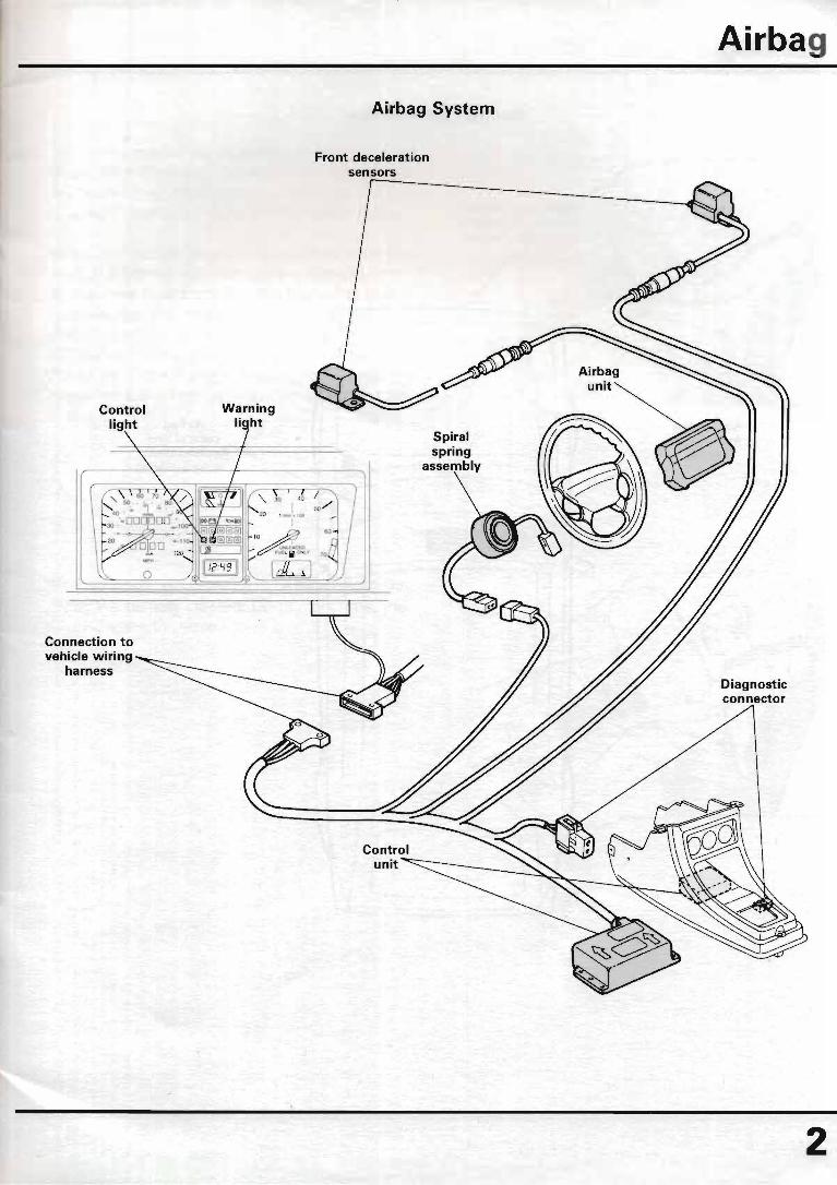
Connection to vehicle wiring
harness
Airbag System
Front deceleration sensors
Spiral spring
assembly
Airbag
Diagnostic connector
2

Airbag
3
Airbag unit in steering
wheel
Component Location
Front deceleration sensors (located in fresh air plenum)
[
Airbag control unit
(located under center console)

Airbag Operation
The airbag system is triggered on the basis of longitudinal (forward) deceleration. The system will not be triggered by lateral (sideways) acceleration or even in the event of a rear impact.
About 10 milliseconds (0.010 seconds) after the start of a frontal collision severe enough to activate the airbag system, the triggering limit is reached and the control unit will send an electrical signal to the detonator. The detonator will then fire the igniter and the solid propellant in the airbag unit will begin to burn. This generates a large amount of nitrogen gas which inflates the airbag.
After about 40 milliseconds (0.040 seconds). the airbag will be fully inflated. During this time, the driver begins to move forward.
Airbag
4

Airbag .
5
Airbag Operation
After about 60 milliseconds (0.060 seconds), the driver's head and upper body will sink into the airbag . The openings on the back of the airbag will allow for a uniform release of gas pressure from the bag.
After about 110 milliseconds (0.110 seconds), the impact has been absorbed and the driver begins to move back into the seat. The airbag is now mostly deflated .

Airbag Unit
The airbag unit is located in the steering wheel. The airbag is folded up and located together with the gas generator in an aluminum housing which is bolted to the steering wheel.
The airbag unit can be removed from the steering wheel by loosening two #30 torx® head bolts on the back of the steering wheel. The bolts are captive and will remain in the steering wheel.
Note: The airbag unit should not be removed or any other service work performed on the system until 20 minutes afterthe battery is disconnected. Th is 20 minute time period allows the system's energy reserve to discharge.
Airbag unit
Airbag
Gas generator
6

Airbag
Airbag
Gas generatfU--1
Discharge holes
The airbag is made from nylon cloth and coated with neoprene on the inside. The bag is held in place with restraining straps and shaped so that it will inflate in the form of a cushion. When inflated, the bag has a gas volume of about 60 liters (15 gallons).
There are four discharge holes located on the back of the airbag, facing away from the driver. Each hole is fitted with a special rubber
7
Horn pad cover
discharge valve which changes the size of its opening based on the pressure inside the airbag.
These holes and valves allow the bag to inflate quickly and deflate uniformly for controlled energy absorption and dissipation as the driver's upper body sinks into the bag.

Airbag
Gas Generator
A gas generator is used to inflate the airbag . The airbag is folded and attached to the top of the gas generator. The assembly is then bolted into the aluminum housing.
The gas generator is filled with two chemicals (sodium azide and potassium nitrate) in tablet form . A detonator and igniter are located in the center.
When the detonator receives an electrical current from the control unit, it will fire the igniter.
Solid propellant
The igniter will then startthe burning of the solid propellant. The solid propellant will burn completely in about 50 milliseconds.
This rapid burning of the two chemicals will produce a large amount of harmless nitrogen gas. This gas will pass through the filter screens where it is cleaned and cooled, and then inflate the airbag.
Igniter
Filter screen
8

Airbag
Spiral spring
B
9
Airbag connector
Male r-n"lnel~tol'<'
Spiral Spring Assembly
Locking piece
Connector for horn contact ring
The wires which connect the airbag to the electrical system are connected to spiral springs. These spiral springs are located in a housing which is bolted to the top of the steering column. The inside of .the spiral spring assembly is splined to the steering column and turns with the wheel to maintain electrical contact with the airbag at all times.
It also contains the wiring for the horn contact ring and the cancel ring for the directionals.
The spiral spring assembly is supplied as a replacement part from the Parts Department with a locking piece. This locking piece fits in the center and is used to lock the assembly in its center position before it is installed on the car. The locking piece must be removed before installing a new spiral spring assembly.
Both the male connector to the spiral spring and the connection in the airbag unit have a short circuit bridge . The bridge connects both terminals in the connector housing whenever it is disconnected. This reduces the risk of activating the airbag during service or repair work .

Spiral Spring Assembly
The spiral spring can only turn about 4 turns in either direction from its center position . Because of this, it is important that the spiral spring assembly is in its center position and that the front wheels are in the straight ahead position if the assembly is removed or installed .
The wiring harness from the spiral spring to the airbag passes through an opening in the back of the steering wheel.
Airbag
Opening in steering wheel
1(]
Airbag
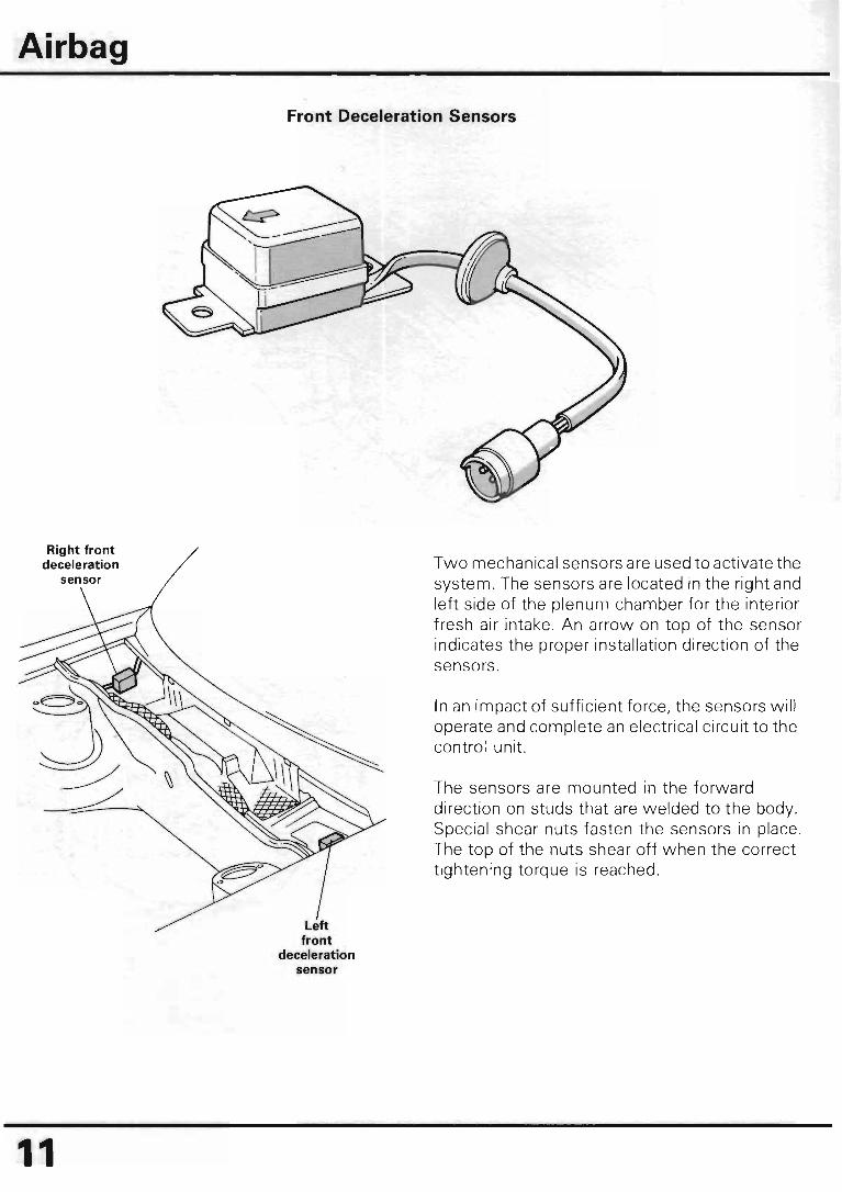
Right front deceleration
sensor
11
Front Deceleration Sensors
Left front
deceleration sensor
Two mechanical sensors are used to activate the system. The sensors are located in the right and left side of the plenum chamber for the interior fresh air intake. An arrow on top of the sensor indicates the proper installation direction of the sensors.
In an impact of sufficient force, the sensors will operate and complete an electrical circuit to the control unit.
The sensors are mounted in the forward direction on studs that are welded to the body. Special shear nuts fasten the sensors in place. The top of the nuts shear off when the correct tightening torque is reached.

Front Deceleration Sensors
The sensors consist of a roller which is mounted on a ramp. A spring band is wrapped around the roller and connected electrically to the control unit. The combination of the spring band together with the ramp will only allow the roller to move forward after a certain deceleration rate is reached in the forward direction.
In a collision of sufficient force, the roller will move forward. The spring band on the roller will then contact another electrical connection inside the sensor. This will close contacts A and Band complete a circuit to the control unit to activate the airbag.
I
I I I I I I
Connections to control unit
L _______ _
Spring band
Contact spring
Stop
® ----- --l I I I I
_____ .-J
Airbac "
1~

Airbag
Left front deceleration sensor
Right front deceleration sensor
900------------------------~~+_--------~~--------~+_~--------------------------
13

, 1
Because of the sensor's design and the way the sensor is installed in the vehicle, the roller will only move forward during longitudinal (forward) deceleration. The sensors will only react to forward impacts within a 30° angle of the center line of the vehicle. The sensors will not react to other forces, such as side impacts, rear impacts, or rollovers.
The high movement threshold of the rollers (approximately 8 to 11 Gs) also eliminates the
Driver's side airbag
+ o----+-....,
Control unit
Safety
I Energy reserve
o
o
o
Airbag
possibility of the airbag being activated by potholes or very rough roads.
The sensors are wired so that only one of the sensors plus the safety sensor needs to operate and close the circuit to activate the airbag.
A safety sensor is also included in the control unit to prevent accidental activation of the airbag. The switch closes at about 2 to 2.5 Gs of forward deceleration. The system then becomes armed.
Left front sensor
Right front sensor
14

Airbag
o
15
o a: <C 3: a: o Ii..
en z w :::IE w en
Control Unit
The airbag system has an electronic control unit that is located under the center console. The control unit has:
• step-up voltage transformer for igniting the airbag
• safety sensor to arm the system
• diagnosis unit with permanent fault memory
• a capacitor to ignite the airbag in the event of a power interruption during an accident
• system wiring harness
°6
Airbag
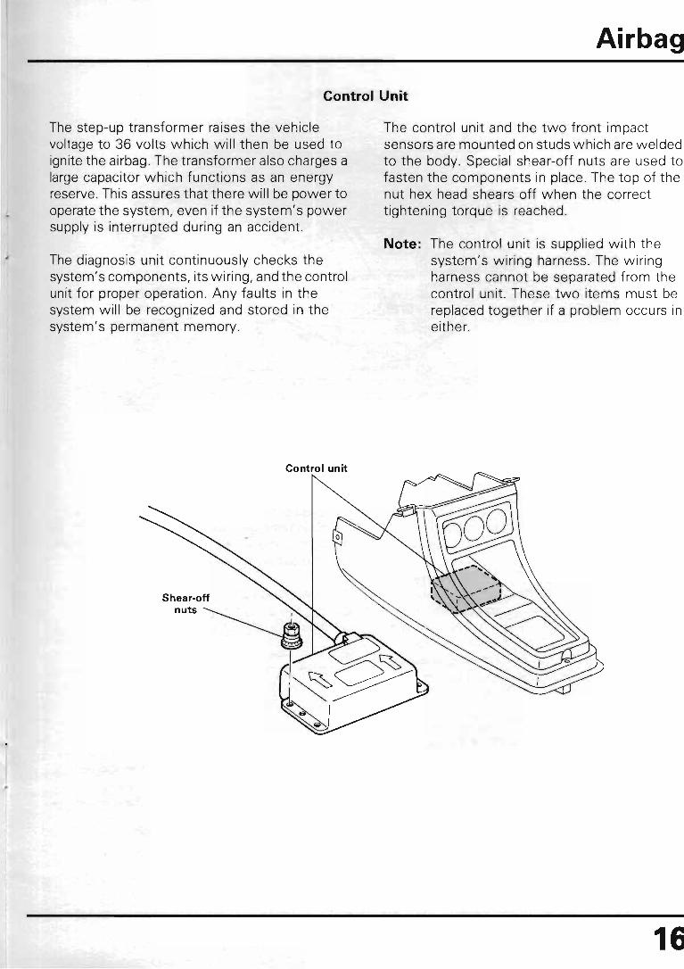
Control Unit
The step-up transformer raises the vehicle voltage to 36 volts which will then be used to ignite the airbag . The transformer also charges a large capacitor which functions as an energy reserve . This assures that there will be power to operate the system, even if the system's power supply is interrupted during an accident.
The diagnosis unit continuously checks the system's components, its wiring, and the control unit for proper operation. Any faults in the system will be recognized and stored in the system's permanent memory.
Control unit
Shear-off
The control unit and the two front impact sensors are mounted on studs which are welded to the body. Special shear-off nuts are used to fasten the components in place. The top of the nut hex head shears off when the correct tightening torque is reached.
Note: The control unit is supplied with the system's wiring harness. The wiring harness cannot be separated from the control unit. These two items must be replaced together if a problem occurs in either.
16
Airbag
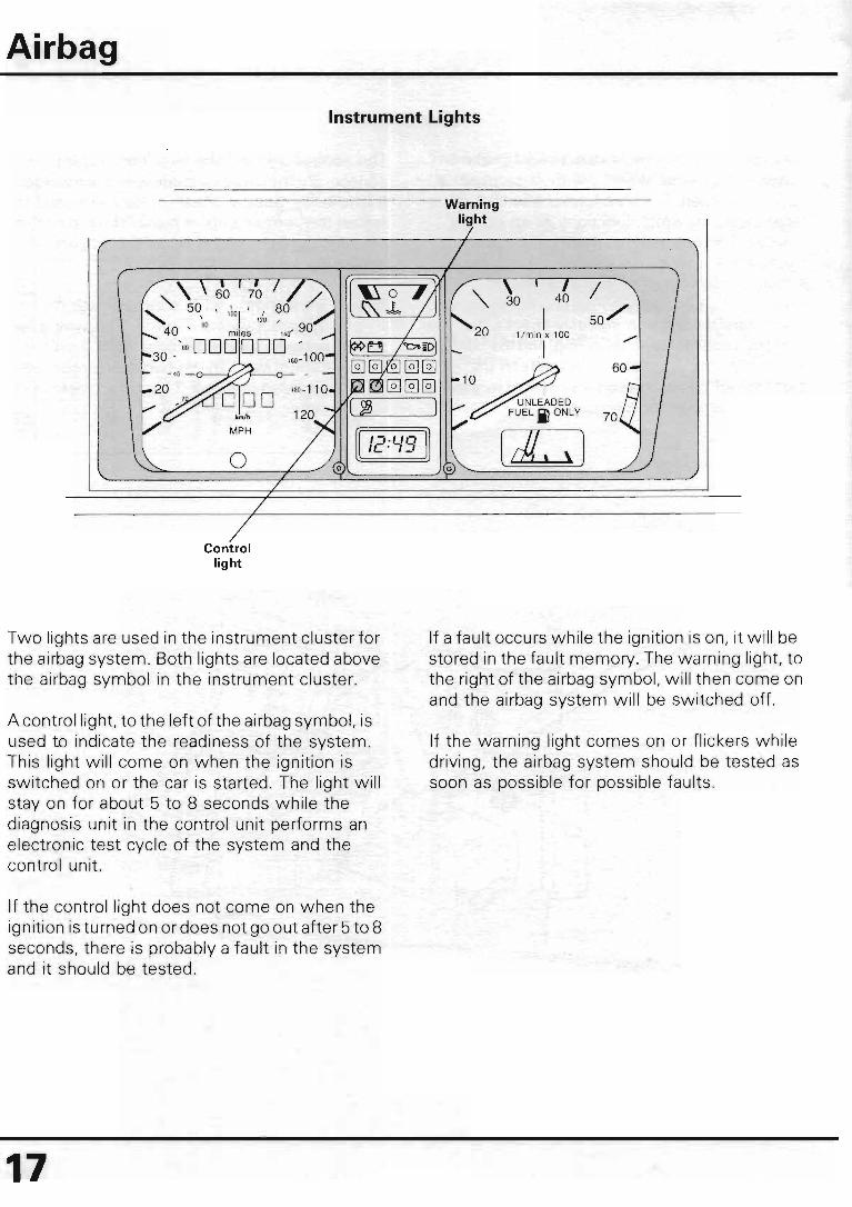
Instrument Lights
Control light
Two lights are used in the instrument cluster for the airbag system. Both lights are located above the airbag symbol in the instrument cluster.
A control light, to the left of the airbag symbol, is used to indicate the readiness of the system. This light will come on when the ignition is switched on or the car is started. The light will stay on for about 5 to 8 seconds while the diagnosis unit in the control unit performs an electronic test cycle of the system and the control unit.
If the control light does not come on when the ignition is turned on or does not go out after 5 to 8 seconds, there is probably a fault in the system and it should be tested .
17
Warning light
If a fault occurs while the ignition is on, it will be stored in the fault memory. The warning light, to the right of the airbag symbol, will then come on and the airbag system will be switched off.
If the warning light comes on or flickers while driving, the airbag system should be tested as soon as possible for possible faults .

Knee Bar
A knee bar is used in combination with the airbag. This prevents the driver from sliding under the steering wheel in the event that the driver is not wearing a seat belt during a frontal collision. On the driver's side, the knee bar consists of a deformable steel shell with a foam covering and a foam insert.
The knee bar is designed to dissipate and absorb the impact of the driver's knees and hold the driver in place. It is attached to the crossmember which is used to reinforce the "A" pillars.
Crossmember
Dashboard
Foam cover
Airbac •
Steel shell

Airbag
Cover seal
Windshield
Windshield frame ----"~
PUR adhesive supplied with
windshield
19
Two-component PUR adhesive
applied to body just prior to
windshield installation
Windshield
Spacing blocks
Interior beading
Windshield
Interior beading
A bonded windshield is installed with the airbag on the Cabriolet. The windshield is bonded in place with a polyurethane adhesive sealant.
If the windshield needs to be replaced, the replacement windshield is supplied from the Parts Department with the frame and a bead of PUR adhesive already installed on the glass. This bead of hardened adhesive will assure a certain gap between the window and the body. This will allow the proper amount of two-component adhesive to be used when installing the new windshield.
A two-component polyurethane (PUR) adhesive, part #D 004300 04, is applied to the body opening to secure the windshield. The vehicle must then be allowed to stand stationary on its wheels for 2 hours. This will allow the adhesive to cure properly.

Elongation element
Front Seat Belts
Cabriolet models equipped with an airbag use a new front seat belt design. Both front seat belts have elongation elements.
The elongation elements consist of a certain length of the seat belt which is folded over in a plastic housing and stitched together. The stitching is designed to separate gradually at a certain force (approximately 450 pounds).
This will allow the belt to gradually lengthen about 4 inches (100 mm). The expansion will result in a more gradual deceleration of the occupant and subject them to less force during a severe frontal collision.
The seat belts must always be replaced after a severe accident. See the Repair Manual for more information .
Safety belt
Airbag
.~\-____ ~Elongation element
Plastic housing
20

Airbag
Steering column tube
21
B
Steering Column
/
"
Steering column
shaft
"
Universal joint shaft
Cabriolets with an airbag also have new steering column components. The universal joint shaft which connects the steering column shaft to the steering rack now has a sliding coupling which will allow the shaft to collapse. The shaft has a spring tab which must be visible through the hole (B) . If not, the two portions of the shaft should be pulled apart until the spring tab snaps in place.
Both of these sliding shafts are used to allow the lower part of the steering column to collapse and minimize movement of the steering wheel, even during a severe frontal collision. This assures optimum positioning of the steering wheel and airbag. "
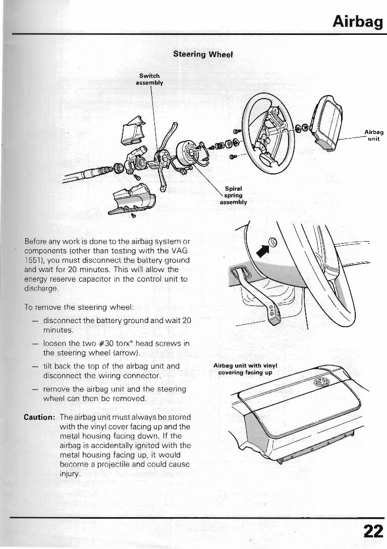
Steering Wheel
Switch assembly
Before any work is done to the airbag system or components (other than testing with the VAG 1551), you must disconnect the battery ground and wait for 20 minutes. This will allow the energy reserve capacitor in the control unit to discharge.
To remove the steering wheel :
disconnect the battery ground and wait 20 minutes.
loosen the two #30 torx® head screws in the steering wheel (arrow).
tilt back the top of the airbag unit and disconnect the wiring connector.
remove the airbag unit and the steering wheel can then be removed .
Caution: The airbag unit must always be stored with the vinyl cover facing up and the metal housing facing down. If the airbag is accidentally ignited with the metal housing facing up, it would become a projectile and could cause inJury.
Spiral spring
assembly
Airbag
22

Airbag
Black connector (power and ground)
Red connector to control unit
23
Log printer
White connector (rapid data connection)
VAG 1551
VAG. SELF-DIAGNOSIS HELP 1 - rapid data transmission
o o
V.A.G
VAG 1551/1
The control unit for the airbag constantly monitors the airbag system and will store any faults in its permanent fault memory. The memory is permanent and will remain even when the battery is disconnected. This memory can be read and the system tested only with the VAG 1551.
A red diagnostic connector is located under the center console together with a black connector. The red connector is connected to the airbag control unit. The black connector is connected to the vehicle's electrical system and provides the VAG 1551 with electrical power and ground.
The VAG 1551 can test the airbag system using the rapid data transfer mode. By selecting address #57, the tester can now perform the following functions on the airbag system:
Check control unit versions
Check fault memory
Erase fault memory
End output
For more information, refer to the Repair Manual.

Airbag
Wiring Diagram
~---------------------------------------------------------------------------------~ 15 15 x 31
-------;:l. 7
B FUEL PUMP
RELAY WARNING
UGHT
~ 024
CONTROL UGHT
\
DlGlFANT POWER SUPPlY RELAY
II ~" 4
\ AI
X 31
'~ \ ,"A8
\f.oo \
\~ ~K75 ~ [)
I) TI , / '" ,,,
0 / 50 8 /50 0 / 15
FROM TII50 TO STARTER FROM T#15
OF IGNITION OF IGNITION
SWITCH SWITCH
I] TS/ 2 ~Y,"' f) TS/ 5 """'" ) TS/3 I'TS/4 , , TS/S f
DIAGNOSTIC CONNECTOR IN CENTER G CONSOLE
AlR8AG , I 'I' (i' I' CONTROL UNIT
:~ I J234 , ~I/ ,I" ,I) \ ) '" ,I, I" I)
I) I ) I ) 0 ) n n TS/ I T3/3 T3/2 T3/ 1 ftall' T3a12 T3a13 T2a11 I )T2a12
3 2 1 1 2 3
~ ) .~ G104 G105
LEFT FRONT RIGHT FRONT DECELERATION DECELERATION
SENSOR SENSOR
2 3 4 5 S 7 8 9
Control Unit Connectors
T6 = 6 point connector behind relay panel T3/T3a = 3 point connector for impact sensors
10 11
~ ~ AlR8AG UNIT
~ ?) ~ ~ N95 .... ~
FI38
SPIRAL SPRING
T2a T2z
12 13 14 15 IS 17 18 19
= 2 point connector for spiral spring = diagnostic connector under console
24

Airbag
Connector below steering column switches
from spiral spring
25
Horn wire
connector
Service Cautions
Trigger switch
If, for any reason, an airbag unit is to be disposed of or thrown away, it must first be activated . An unignited airbag gas generator could cause injury if activated unintentionally.
To activate the airbag unit, a special wire harness (as pictured above) should be used. The wire harness must be at least 30 feet long and is connected to the connector from the spiral spring, which is located under the cover beneath the steering column switches.
The other end of the harness is connected to a separate 12 volt battery (other than the vehicle's). The airbag can then be ignited in the vehicle while it is mounted in the steering wheel. For more information on this procedure, refer to the airbag information in the Repair Manual, Group 96.

Service Cautions
The airbag system must be replaced 10 years after the date of manufacture.
Other precautions must be followed with the airbag system:
• The airbag system can only be tested with VAG 1551 using rapid data transmission .
• Airbag system parts should never be opened or repaired . Always use new parts.
• Airbag parts should not be left unattended. They should be installed in the vehicle immediately after obtaining them.
• Airbag components that have been dropped more than 18 inches should not be used .
• Chemical cleaners or oil and grease should not come in contact with the vinyl covering on the airbag unit.
• Do not place any stickers or covers on the steering wheel.
• Always disconnect the battery when doing any electric welding on the vehicle.
Airbag
26

WSP-521 -205-00
WE ENCOURAGE PROFESSIONALISM THROUGH TECHNICIAN CERTIFICATION