automatic (ball drip) drain valves: 1. manufacturers: subject to compliance with requirements,...
TRANSCRIPT


GRDA Engineering & Technology Center Remodel DCS#ID13032-5
Tulsa, OK
For Construction 211313 06/21/2013
Page 1 of 15
SECTION 211313 - WET-PIPE SPRINKLER SYSTEMS
PART 1 - GENERAL
1.1 SUMMARY
A. Section Includes:
1. Pipes, fittings, and specialties.
2. Fire-protection valves.
3. Fire-department connections.
4. Sprinklers.
5. Alarm devices.
6. Pressure gages.
B. Related Sections:
1. NA
1.2 SYSTEM DESCRIPTIONS
A. Wet-Pipe Sprinkler System: Automatic sprinklers are attached to piping containing water and
that is connected to water supply through alarm valve. Water discharges immediately from
sprinklers when they are opened. Sprinklers open when heat melts fusible link or destroys
frangible device.
B. The contractor shall fully & completely coordinate all items between the fire alarm, fire
suppression, mechanical, and electrical contractors & per the plans. The contractor shall provide
integrated systems as indicated on the plans.
C. The contractor shall provide complete fire sprinkler coverage of the facility to include any
overhangs, porches, breezeways, exterior architectural features, etc… as required by the A.H.J.
1.3 PERFORMANCE REQUIREMENTS
A. Standard-Pressure Piping System Component: Listed for 175-psig minimum working pressure.
B. Delegated Design: Design sprinkler system(s), including comprehensive engineering analysis
by a qualified professional engineer, using performance requirements and design criteria
indicated.
1. Available fire-hydrant flow test records indicate the following conditions: PLEASE
NOTE – the fire sprinkler contractor shall be required to perform their own fire hydrant
flow test and provide the results of the flow test along with their fire sprinkler submittal
package. The contractor shall utilize their own flow test results for this project.
a. Date: TBD

GRDA Engineering & Technology Center Remodel DCS#ID13032-5
Tulsa, OK
For Construction 211313 06/21/2013
Page 2 of 15
b. Time: TBD
c. Performed by: TBD
d. Location of Residual Fire Hydrant R: TB
e. Location of Flow Fire Hydrant F: TBD
f. Static Pressure at Residual Fire Hydrant R: TBD
g. Measured Flow at Flow Fire Hydrant F: TBD
h. Residual Pressure at Residual Fire Hydrant R: TBD
C. Sprinkler system design shall be approved by authorities having jurisdiction.
1. Margin of Safety for Available Water Flow and Pressure: 10 PSI, including losses
through water-service piping, valves, and backflow preventers.
2. Sprinkler Occupancy Hazard Classifications:
a. Building Service Areas: Ordinary Hazard, Group 1
b. Electrical Equipment Rooms: Ordinary Hazard, Group 1
c. General Storage Areas: Ordinary Hazard, Group 1
d. Machine Shops: Ordinary Hazard, Group 2
e. Mechanical Equipment Rooms: Ordinary Hazard, Group 1
f. Office and Public Areas: Light Hazard
3. Minimum Density for Automatic-Sprinkler Piping Design:
a. Light-Hazard Occupancy: 0.10 gpm over 1500-sq. ft. area.
b. Ordinary-Hazard, Group 1 Occupancy: 0.15 gpm over 1500-sq. ft. area.
c. Ordinary-Hazard, Group 2 Occupancy: 0.20 gpm over 1500-sq. ft. area.
4. Maximum Protection Area per Sprinkler: Per UL listing.
5. Maximum Protection Area per Sprinkler:
a. Residential Areas: 400 sq. ft.
b. Office Spaces: 225 sq. ft.
c. Storage Areas: 130 sq. ft.
d. Mechanical Equipment Rooms: 130 sq. ft.
e. Electrical Equipment Rooms: 130 sq. ft.
f. Other Areas: According to NFPA 13 recommendations unless otherwise indicated.
6. Total Combined Hose-Stream Demand Requirement: According to NFPA 13
D. Seismic Performance: Sprinkler piping shall withstand the effects of earthquake motions
determined according to NFPA 13 and ASCE/SEI 7
1.4 SUBMITTALS
A. Product Data: For each type of product indicated.
B. Hydraulic Calculations.
C. Shop Drawings: For wet-pipe sprinkler systems. Include plans, elevations, sections, details,
and attachments to other work.
1. Wiring Diagrams: For power, signal, and control wiring.

GRDA Engineering & Technology Center Remodel DCS#ID13032-5
Tulsa, OK
For Construction 211313 06/21/2013
Page 3 of 15
D. Delegated-Design Submittal: For sprinkler systems indicated to comply with performance
requirements and design criteria, including analysis data signed and sealed by the qualified
professional engineer responsible for their preparation.
E. Qualification Data: For qualified Installer
F. Approved Sprinkler Piping Drawings: Working plans, prepared according to NFPA 13, that
have been approved by authorities having jurisdiction, including hydraulic calculations.
G. Welding certificates.
H. Field Test Reports and Certificates: Indicate and interpret test results for compliance with
performance requirements and as described in NFPA 13. Include "Contractor's Material and
Test Certificate for Aboveground Piping."
I. Field quality-control reports.
J. Operation and maintenance data.
1.5 QUALITY ASSURANCE
A. Installer Qualifications:
1. Installer's responsibilities include designing, fabricating, and installing sprinkler systems
and providing professional engineering services needed to assume engineering
responsibility. Base calculations on results of fire-hydrant flow test.
a. Engineering Responsibility: Preparation of working plans, calculations, and field
test reports by a qualified professional engineer.
B. Welding Qualifications: Qualify procedures and operators according to ASME Boiler and
Pressure Vessel Code.
C. Electrical Components, Devices, and Accessories: Listed and labeled as defined in NFPA 70,
by a qualified testing agency, and marked for intended location and application.
D. NFPA Standards: Sprinkler system equipment, specialties, accessories, installation, and testing
shall comply with the following:
1. NFPA 13, "Installation of Sprinkler Systems."
2. NFPA 13R, "Installation of Sprinkler Systems in Residential Occupancies up to and
Including Four Stories in Height."
3. NFPA 24, "Installation of Private Fire Service Mains and Their Appurtenances."

GRDA Engineering & Technology Center Remodel DCS#ID13032-5
Tulsa, OK
For Construction 211313 06/21/2013
Page 4 of 15
PART 2 - PRODUCTS
2.1 PIPING MATERIALS
A. Comply with requirements in "Piping Schedule" Article for applications of pipe, tube, and
fitting materials, and for joining methods for specific services, service locations, and pipe sizes.
2.2 STEEL PIPE AND FITTINGS
A. Standard Weight, Black-Steel Pipe: ASTM A 53/A 53M. Pipe ends may be factory or field
formed to match joining method.
B. Black-Steel Pipe Nipples: ASTM A 733, made of ASTM A 53/A 53M, standard-weight,
seamless steel pipe with threaded ends.
C. Malleable- or Ductile-Iron Unions: UL 860.
D. Cast-Iron Flanges: ASME 16.1, Class 125.
E. Steel Flanges and Flanged Fittings: ASME B16.5, Class 150.
F. Steel Welding Fittings: ASTM A 234/A 234M and ASME B16.9.
G. Grooved-Joint, Steel-Pipe Appurtenances:
1. Manufacturers: Subject to compliance with requirements, provide products by one of the
following
a. Anvil International, Inc.
b. Tyco Fire & Building Products LP.
c. Victaulic Company.
2. Pressure Rating: 175 psig minimum.
3. Galvanized and Uncoated, Grooved-End Fittings for Steel Piping: ASTM A 47/A 47M,
malleable-iron casting or ASTM A 536, ductile-iron casting; with dimensions matching
steel pipe.
4. Grooved-End-Pipe Couplings for Steel Piping: AWWA C606 and UL 213, rigid pattern,
unless otherwise indicated, for steel-pipe dimensions. Include ferrous housing sections,
EPDM-rubber gasket, and bolts and nuts.
H. Steel Pressure-Seal Fittings: UL 213, FM-approved, 175-psig pressure rating with steel
housing, rubber O-rings, and pipe stop; for use with fitting manufacturers' pressure-seal tools.
1. Manufacturers: Subject to compliance with requirements, provide products by one of the
following
a. Victaulic Company.

GRDA Engineering & Technology Center Remodel DCS#ID13032-5
Tulsa, OK
For Construction 211313 06/21/2013
Page 5 of 15
2.3 PIPING JOINING MATERIALS
A. Pipe-Flange Gasket Materials: AWWA C110, rubber, flat face, 1/8 inch thick or
ASME B16.21, nonmetallic and asbestos free.
1. Class 125, Cast-Iron Flat-Face Flanges: Full-face gaskets.
B. Metal, Pipe-Flange Bolts and Nuts: ASME B18.2.1, carbon steel unless otherwise indicated.
C. Welding Filler Metals: Comply with AWS D10.12M/D10.12 for welding materials appropriate
for wall thickness and chemical analysis of steel pipe being welded.
2.4 LISTED FIRE-PROTECTION VALVES
A. General Requirements:
1. Valves shall be UL listed or FM approved.
2. Minimum Pressure Rating: 175 psig
B. Check Valves:
1. Manufacturers: Subject to compliance with requirements, provide products by one of the
following
a. Anvil International, Inc.
b. Crane Co.; Crane Valve Group; Crane Valves.
c. Crane Co.; Crane Valve Group; Stockham Division.
d. Mueller Co.; Water Products Division.
e. NIBCO INC.
f. Potter Roemer.
g. Tyco Fire & Building Products LP.
h. Victaulic Company.
i. Viking Corporation.
j. Watts Water Technologies, Inc.
2. Standard: UL 312.
3. Pressure Rating: 250 psig minimum
4. Type: Swing check.
5. Body Material: Cast iron.
6. End Connections: Flanged or grooved.
C. Bronze OS&Y Gate Valves:
1. Manufacturers: Subject to compliance with requirements, provide products by one of the
following
a. Crane Co.; Crane Valve Group; Crane Valves.
b. NIBCO INC.
2. Standard: UL 262.
3. Pressure Rating: 175 psig

GRDA Engineering & Technology Center Remodel DCS#ID13032-5
Tulsa, OK
For Construction 211313 06/21/2013
Page 6 of 15
4. Body Material: Bronze.
5. End Connections: Threaded.
D. Iron OS&Y Gate Valves:
1. Manufacturers: Subject to compliance with requirements, provide products by one of the
following
a. Crane Co.; Crane Valve Group; Crane Valves.
b. Milwaukee Valve Company.
c. Mueller Co.; Water Products Division.
d. NIBCO INC.
e. Tyco Fire & Building Products LP.
f. Watts Water Technologies, Inc.
2. Standard: UL 262.
3. Pressure Rating: 250 psig minimum
4. Body Material: Cast or ductile iron.
5. End Connections: Flanged or grooved.
E. Indicating-Type Butterfly Valves:
1. Manufacturers: Subject to compliance with requirements, provide products by one of the
following
a. Milwaukee Valve Company.
b. NIBCO INC.
c. Tyco Fire & Building Products LP.
d. Victaulic Company.
2. Standard: UL 1091.
3. Pressure Rating: 175 psig minimum.
4. Valves NPS 2 and Smaller:
a. Valve Type: Ball or butterfly.
b. Body Material: Bronze.
c. End Connections: Threaded.
5. Valves NPS 2-1/2 and Larger:
a. Valve Type: Butterfly.
b. Body Material: Cast or ductile iron.
c. End Connections: Flanged, grooved, or wafer.
6. Valve Operation: Integral electrical, 115-V ac, prewired, single-circuit, supervisory
switch visual indicating device.
2.5 TRIM AND DRAIN VALVES
A. General Requirements:

GRDA Engineering & Technology Center Remodel DCS#ID13032-5
Tulsa, OK
For Construction 211313 06/21/2013
Page 7 of 15
1. Standard: UL's "Fire Protection Equipment Directory" listing or "Approval Guide,"
published by FM Global, listing.
2. Minimum Pressure Rating: 175 psig
B. Ball Valves:
1. Manufacturers: Subject to compliance with requirements, provide products by one of the
following
a. Anvil International, Inc.
b. Flowserve.
c. FNW.
d. NIBCO INC.
e. Potter Roemer.
f. Tyco Fire & Building Products LP.
g. Victaulic Company.
h. Watts Water Technologies, Inc.
2.6 SPECIALTY VALVES
A. General Requirements:
1. Standard: UL's "Fire Protection Equipment Directory" listing or "Approval Guide,"
published by FM Global, listing.
2. Minimum Pressure Rating: 175 psig
3. Body Material: Cast or ductile iron.
4. Size: Same as connected piping.
5. End Connections: Flanged or grooved.
B. Automatic (Ball Drip) Drain Valves:
1. Manufacturers: Subject to compliance with requirements, provide products by one of the
following
a. Reliable Automatic Sprinkler Co., Inc.
b. Tyco Fire & Building Products LP.
2. Standard: UL 1726.
3. Pressure Rating: 175 psig minimum.
4. Type: Automatic draining, ball check.
5. Size: NPS 3/4
6. End Connections: Threaded.
2.7 FIRE-DEPARTMENT CONNECTIONS
1. Coordinate with local fire department
2.8 SPRINKLER SPECIALTY PIPE FITTINGS
A. Branch Outlet Fittings:

GRDA Engineering & Technology Center Remodel DCS#ID13032-5
Tulsa, OK
For Construction 211313 06/21/2013
Page 8 of 15
1. Manufacturers: Subject to compliance with requirements, provide products by one of the
following
a. Tyco Fire & Building Products LP.
b. Victaulic Company.
2. Standard: UL 213.
3. Pressure Rating: 175 psig minimum
4. Body Material: Ductile-iron housing with EPDM seals and bolts and nuts.
5. Type: Mechanical-T and -cross fittings.
6. Configurations: Snap-on and strapless, ductile-iron housing with branch outlets.
7. Size: Of dimension to fit onto sprinkler main and with outlet connections as required to
match connected branch piping.
8. Branch Outlets: Grooved, plain-end pipe, or threaded.
B. Flow Detection and Test Assemblies:
1. Manufacturers: Subject to compliance with requirements, provide products by one of the
following
a. Reliable Automatic Sprinkler Co., Inc.
b. Tyco Fire & Building Products LP.
c. Victaulic Company.
2. Standard: UL's "Fire Protection Equipment Directory" listing or "Approval Guide,"
published by FM Global, listing.
3. Pressure Rating: 175 psig minimum
4. Body Material: Cast- or ductile-iron housing with orifice, sight glass, and integral test
valve.
5. Size: Same as connected piping.
6. Inlet and Outlet: Threaded.
C. Branch Line Testers:
1. Manufacturers: Subject to compliance with requirements, provide products by one of the
following
a. Elkhart Brass Mfg. Company, Inc.
b. Fire-End & Croker Corporation.
c. Potter Roemer.
2. Standard: UL 199.
3. Pressure Rating: 175 psig minimum.
4. Body Material: Brass.
5. Size: Same as connected piping.
6. Inlet: Threaded.
7. Drain Outlet: Threaded and capped.
8. Branch Outlet: Threaded, for sprinkler.
D. Sprinkler Inspector's Test Fittings:
1. Manufacturers: Subject to compliance with requirements, provide products by one of the
following

GRDA Engineering & Technology Center Remodel DCS#ID13032-5
Tulsa, OK
For Construction 211313 06/21/2013
Page 9 of 15
a. Tyco Fire & Building Products LP.
b. Victaulic Company.
c. Viking Corporation.
2. Standard: UL's "Fire Protection Equipment Directory" listing or "Approval Guide,"
published by FM Global, listing.
3. Pressure Rating: 175 psig minimum
4. Body Material: Cast- or ductile-iron housing with sight glass.
5. Size: Same as connected piping.
6. Inlet and Outlet: Threaded.
E. Adjustable Drop Nipples:
1. Manufacturers: Subject to compliance with requirements, provide products by one of the
following
a. CECA, LLC.
b. Corcoran Piping System Co.
c. Merit Manufacturing; a division of Anvil International, Inc.
2. Standard: UL 1474.
3. Pressure Rating: 250 psig minimum
4. Body Material: Steel pipe with EPDM-rubber O-ring seals.
5. Size: Same as connected piping.
6. Length: Adjustable.
7. Inlet and Outlet: Threaded.
F. Flexible, Sprinkler Hose Fittings:
1. Manufacturers: Subject to compliance with requirements, provide products by one of the
following
a. Fivalco Inc.
b. FlexHead Industries, Inc.
c. Gateway Tubing, Inc.
2. Standard: UL 1474.
3. Type: Flexible hose for connection to sprinkler, and with bracket for connection to
ceiling grid.
4. Pressure Rating: 175 psig minimum
5. Size: Same as connected piping, for sprinkler.
2.9 SPRINKLERS
A. Manufacturers: Subject to compliance with requirements, provide products by one of the
following
1. Reliable Automatic Sprinkler Co., Inc.
2. Tyco Fire & Building Products LP.
3. Victaulic Company.
4. Viking Corporation.

GRDA Engineering & Technology Center Remodel DCS#ID13032-5
Tulsa, OK
For Construction 211313 06/21/2013
Page 10 of 15
B. General Requirements:
1. Standard: UL's "Fire Protection Equipment Directory" listing or "Approval Guide,"
published by FM Global, listing.
2. Pressure Rating for Residential Sprinklers: 175 psig maximum.
3. Pressure Rating for Automatic Sprinklers: 175 psig minimum.
4. Pressure Rating for High-Pressure Automatic Sprinklers: 250 psig minimum
C. Automatic Sprinklers with Heat-Responsive Element:
1. Early-Suppression, Fast-Response Applications: UL 1767
2. Nonresidential Applications: UL 199
3. Residential Applications: UL 1626
4. Characteristics: Nominal 1/2-inch orifice with Discharge Coefficient K of 5.6, and for
"Ordinary" temperature classification rating unless otherwise indicated or required by
application.
D. Sprinkler Finishes:
1. Chrome plated.
2. Bronze.
3. Painted.
E. Special Coatings:
1. Wax.
2. Lead.
3. Corrosion-resistant paint.
F. Sprinkler Escutcheons: Materials, types, and finishes for the following sprinkler mounting
applications. Escutcheons for concealed, flush, and recessed-type sprinklers are specified with
sprinklers.
1. Ceiling Mounting: Chrome-plated steel, two piece, with 1-inch (25-mm) vertical
adjustment
G. Sprinkler Guards:
1. Manufacturers: Subject to compliance with requirements, provide products by one of the
following
a. Reliable Automatic Sprinkler Co., Inc.
b. Tyco Fire & Building Products LP.
c. Victaulic Company.
d. Viking Corporation.
2. Standard: UL 199.
3. Type: Wire cage with fastening device for attaching to sprinkler.
GRDA Engineering & Technology Center Remodel DCS#ID13032-5
Tulsa, OK
For Construction 211313 06/21/2013
Page 11 of 15
2.10 ALARM DEVICES
1.
B. Water-Flow Indicators:
1. Manufacturers: Subject to compliance with requirements, provide products by one of the
following
a. Potter Electric Signal Company.
b. System Sensor; a Honeywell company.
c. Viking Corporation.
2. Standard: UL 346.
3. Water-Flow Detector: Electrically supervised.
4. Components: Two single-pole, double-throw circuit switches for isolated alarm and
auxiliary contacts, 7 A, 125-V ac and 0.25 A, 24-V dc; complete with factory-set, field-
adjustable retard element to prevent false signals and tamperproof cover that sends signal
if removed.
5. Type: Paddle operated.
6. Pressure Rating: 250 psig
7. Design Installation: Horizontal or vertical.
C. Valve Supervisory Switches:
1. Manufacturers: Subject to compliance with requirements, provide products by one of the
following
a. Fire-Lite Alarms, Inc.; a Honeywell company.
b. Kennedy Valve; a division of McWane, Inc.
c. Potter Electric Signal Company.
d. System Sensor; a Honeywell company.
2. Standard: UL 346.
3. Type: Electrically supervised.
4. Components: Single-pole, double-throw switch with normally closed contacts.
5. Design: Signals that controlled valve is in other than fully open position.
2.11 PRESSURE GAGES
A. Manufacturers: Subject to compliance with requirements, provide products by one of the
following
1. AMETEK; U.S. Gauge Division.
2. Ashcroft, Inc.
3. Brecco Corporation.
B. Standard: UL 393.
C. Dial Size: 3-1/2- to 4-1/2-inch diameter.
D. Pressure Gage Range: 0 to 250 psig minimum

GRDA Engineering & Technology Center Remodel DCS#ID13032-5
Tulsa, OK
For Construction 211313 06/21/2013
Page 12 of 15
E. Water System Piping Gage: Include "WATER" or "AIR/WATER" label on dial face.
F. Air System Piping Gage: Include retard feature and "AIR" or "AIR/WATER" label on dial
face.
PART 3 - EXECUTION
3.1 SERVICE-ENTRANCE PIPING
A. Connect sprinkler piping to water-service piping for service entrance to building. Comply with
requirements as indicated on plans.
B. Install shutoff valve, backflow preventer, pressure gage, drain, and other accessories indicated
at connection to water-service piping
C. Install shutoff valve, check valve, pressure gage, and drain at connection to water service.
3.2 WATER-SUPPLY CONNECTIONS
A. Install shutoff valve, backflow preventer, pressure gage, drain, and other accessories indicated
at connection to water-distribution piping
B. Install shutoff valve, check valve, pressure gage, and drain at connection to water supply.
3.3 PIPING INSTALLATION
A. Locations and Arrangements: Drawing plans, schematics, and diagrams indicate general
location and arrangement of piping. Install piping as indicated, as far as practical.
1. Deviations from approved working plans for piping require written approval from
authorities having jurisdiction. File written approval with Architect before deviating
from approved working plans.
B. Piping Standard: Comply with requirements for installation of sprinkler piping in NFPA 13.
C. Install seismic restraints on piping. Comply with requirements for seismic-restraint device
materials and installation in NFPA 13.
D. Use listed fittings to make changes in direction, branch takeoffs from mains, and reductions in
pipe sizes.
E. Install unions adjacent to each valve in pipes NPS 2 and smaller.
F. Install flanges, flange adapters, or couplings for grooved-end piping on valves, apparatus, and
equipment having NPS 2-1/2 and larger end connections.
G. Install "Inspector's Test Connections" in sprinkler system piping, complete with shutoff valve,
and sized and located according to NFPA 13.

GRDA Engineering & Technology Center Remodel DCS#ID13032-5
Tulsa, OK
For Construction 211313 06/21/2013
Page 13 of 15
H. Install sprinkler piping with drains for complete system drainage.
I. Install sprinkler control valves, test assemblies, and drain risers adjacent to standpipes when
sprinkler piping is connected to standpipes.
J. Install automatic (ball drip) drain valve at each check valve for fire-department connection, to
drain piping between fire-department connection and check valve. Install drain piping to and
spill over floor drain or to outside building.
K. Install alarm devices in piping systems.
L. Install hangers and supports for sprinkler system piping according to NFPA 13. Comply with
requirements for hanger materials in NFPA 13.
M. Install pressure gages on riser or feed main, at each sprinkler test connection, and at top of each
standpipe. Include pressure gages with connection not less than NPS 1/4 and with soft metal
seated globe valve, arranged for draining pipe between gage and valve. Install gages to permit
removal, and install where they will not be subject to freezing.
N. Fill sprinkler system piping with water.
O. Install sleeves for piping penetrations of walls, ceilings, and floors.
P. Install sleeve seals for piping penetrations of concrete walls and slabs.
Q. Install escutcheons for piping penetrations of walls, ceilings, and floors.
3.4 JOINT CONSTRUCTION
A. Install couplings, flanges, flanged fittings, unions, nipples, and transition and special fittings
that have finish and pressure ratings same as or higher than system's pressure rating for
aboveground applications unless otherwise indicated.
B. Install unions adjacent to each valve in pipes NPS 2 and smaller.
C. Install flanges, flange adapters, or couplings for grooved-end piping on valves, apparatus, and
equipment having NPS 2-1/2 and larger end connections.
D. Ream ends of pipes and tubes and remove burrs. Bevel plain ends of steel pipe.
E. Remove scale, slag, dirt, and debris from inside and outside of pipes, tubes, and fittings before
assembly.
F. Flanged Joints: Select appropriate gasket material in size, type, and thickness suitable for water
service. Join flanges with gasket and bolts according to ASME B31.9.
G. Threaded Joints: Thread pipe with tapered pipe threads according to ASME B1.20.1. Cut
threads full and clean using sharp dies. Ream threaded pipe ends to remove burrs and restore
full ID. Join pipe fittings and valves as follows:
1. Apply appropriate tape or thread compound to external pipe threads.

GRDA Engineering & Technology Center Remodel DCS#ID13032-5
Tulsa, OK
For Construction 211313 06/21/2013
Page 14 of 15
2. Damaged Threads: Do not use pipe or pipe fittings with threads that are corroded or
damaged.
H. Twist-Locked Joints: Insert plain end of steel pipe into plain-end-pipe fitting. Rotate retainer
lugs one-quarter turn or tighten retainer pin.
I. Steel-Piping, Pressure-Sealed Joints: Join lightwall steel pipe and steel pressure-seal fittings
with tools recommended by fitting manufacturer.
J. Welded Joints: Construct joints according to AWS D10.12M/D10.12, using qualified processes
and welding operators according to "Quality Assurance" Article.
1. Shop weld pipe joints where welded piping is indicated. Do not use welded joints for
galvanized-steel pipe.
K. Steel-Piping, Cut-Grooved Joints: Cut square-edge groove in end of pipe according to
AWWA C606. Assemble coupling with housing, gasket, lubricant, and bolts. Join steel pipe
and grooved-end fittings according to AWWA C606 for steel-pipe joints.
L. Dissimilar-Material Piping Joints: Make joints using adapters compatible with materials of both
piping systems.
3.5 VALVE AND SPECIALTIES INSTALLATION
A. Install listed fire-protection valves, trim and drain valves, specialty valves and trim, controls,
and specialties according to NFPA 13 and authorities having jurisdiction.
B. Install listed fire-protection shutoff valves supervised open, located to control sources of water
supply except from fire-department connections. Install permanent identification signs
indicating portion of system controlled by each valve.
C. Install check valve in each water-supply connection. Install backflow preventers instead of
check valves in potable-water-supply sources.
D. Specialty Valves:
1. General Requirements: Install in vertical position for proper direction of flow, in main
supply to system.
2. Alarm Valves: Include bypass check valve and retarding chamber drain-line connection.
3.6 SPRINKLER INSTALLATION
A. Install sprinklers in suspended ceilings in center of narrow dimension of acoustical ceiling
panels.
B. Install dry-type sprinklers with water supply from heated space. Do not install pendent or
sidewall, wet-type sprinklers in areas subject to freezing.
C. Install sprinklers into flexible, sprinkler hose fittings and install hose into bracket on ceiling
grid.

GRDA Engineering & Technology Center Remodel DCS#ID13032-5
Tulsa, OK
For Construction 211313 06/21/2013
Page 15 of 15
3.7 FIRE-DEPARTMENT CONNECTION INSTALLATION
A. Install wall-type, fire-department connections.
B. Install automatic (ball drip) drain valve at each check valve for fire-department connection.
3.8 IDENTIFICATION
A. Install labeling and pipe markers on equipment and piping according to requirements in
NFPA 13.
3.9 FIELD QUALITY CONTROL
A. Perform tests and inspections.
B. Tests and Inspections:
1. Leak Test: After installation, charge systems and test for leaks. Repair leaks and retest
until no leaks exist.
2. Test and adjust controls and safeties. Replace damaged and malfunctioning controls and
equipment.
3. Flush, test, and inspect sprinkler systems according to NFPA 13, "Systems Acceptance"
Chapter.
4. Energize circuits to electrical equipment and devices.
5. Coordinate with fire-alarm tests. Operate as required.
6. Coordinate with fire-pump tests. Operate as required.
7. Verify that equipment hose threads are same as local fire-department equipment.
C. Sprinkler piping system will be considered defective if it does not pass tests and inspections.
D. Prepare test and inspection reports.
3.10 CLEANING
A. Clean dirt and debris from sprinklers.
B. Remove and replace sprinklers with paint other than factory finish.
END OF SECTION 211313


GRDA Engineering & Technology Center Remodel DCS#ID13032-5
Tulsa, OK
For Construction 212200 06/21/2013
Page 1 of 23
SECTION 212200 - GASEOUS SUPPRESSION SYSTEMS
PART 1 - GENERAL
1.1 RELATED DOCUMENTS
A. Drawings and general provisions of contract, including general and supplemental conditions and
Division 1 specification sections apply to work of this section.
1. Section 283111: Fire Alarm Systems
1.2 DESCRIPTION OF WORK
A. Provide all materials and labor for the design, engineering and installation of FM-200 or Novec
1230 fixed gaseous suppression systems in rooms and areas indicated on the project drawings.
B. The project drawings show locations where systems are to be installed and the proposed
locations for new devices, appliances and equipment. Design of the individual systems shall be
in accordance with these specifications. The Contractor is responsible for the detailed design
and engineering for installation in accordance with these specifications. These specifications
and drawings do not necessarily contain all information required for design and installation of
the system, but are intended to be used as a guide for the purposes of system conceptual design
and preparing bids. As such, they indicate:
1. Requirements for fixed gaseous suppression system protection.
2. Types and minimum installation criteria for system devices.
3. Locations for system devices and equipment.
4. Minimum design requirements.
1.3 BASE BID
A. The Owner and Owner’s Fire Protection Consultant will determine which agent will be utilized.
Systems will be either all FM-200 or all Novec 1230.
1.4 REFERENCES
A. All work shall be installed in accordance with these applicable codes and all referenced design
standards:
1. International Building Code
2. National Electrical Code (NEC)
3. NFPA 72
4. NFPA 2001
1.5 SYSTEM DESCRIPTION
A. This section describes the requirements for furnishing and installing engineered fire detection
and total flooding FM-200 or Novec 1230 gaseous agent fire suppression systems.

GRDA Engineering & Technology Center Remodel DCS#ID13032-5
Tulsa, OK
For Construction 212200 06/21/2013
Page 2 of 23
B. All work shall be performed in accordance with these specifications, including related division
sections and drawings. The drawings indicate the areas to receive detection and fixed gaseous
suppression systems. The Contractor is to review all drawings so that all items affecting the
operation of the fire detection/ suppression system (such as equipment location, air diffusers,
damper closures, door openings) are considered in the design of the engineered systems.
C. The work shall include, but shall not be limited to the following:
1. Furnish and install all materials necessary for complete total flooding fire suppression
systems consisting of:
a. Fixed gaseous suppression systems including piping networks.
b. Complete control and detection systems.
c. Addressable alarm initiating devices.
d. Horn/visual and bell appliances.
e. Form C relay contacts.
f. Interfaces with damper controls, HVAC shut down and AC power shutdowns.
g. Batteries.
h. Primary input power - 120 Vac, 50/60 Hz.
i. All necessary wiring, conduit, and labor.
j. All signage required by NFPA 2001.
k. Interface to building fire alarm system
2. Testing and adjusting all new equipment and systems as required by the manufacturer,
NFPA 2001, NFPA 72 and these specifications.
3. Preparing and submitting shop drawing with calculations and all other submittals
required.
4. Preparing and submitting as-built drawing with calculations as installed and all other
submittals required.
5. Patching and painting.
6. Provide a warranty.
7. Provide emergency service.
8. Provide training.
9. Obtain all necessary permits.
10. System certifications indicating the systems are installed and tested in accordance with all
applicable codes and the manufacturer’s installation guidelines.
D. Provide a minimum of four (4) hours for training staff personnel in the operation and use of the
new systems.
E. The location of system equipment and devices to be installed can be more specifically described
as:
1. Installation of new FM-200 or Novec 1230 gaseous suppression systems where indicated
on the project drawings. Installation will be as required by these contract documents and
the applicable codes.
1.6 QUALITY ASSURANCE
A. All work shall meet the requirements of the Owner, AHJ, and Owner’s Fire Protection
Consultant.

GRDA Engineering & Technology Center Remodel DCS#ID13032-5
Tulsa, OK
For Construction 212200 06/21/2013
Page 3 of 23
B. All equipment and components shall be listed by Underwriters' Laboratories for the actual
intended use unless hereinafter specifically excluded from such a listing.
C. Installation and supervision of installation shall be in strict compliance with the requirements of
the regulations, licenses, and permits for gaseous suppression system installers in their
jurisdictions.
D. Installer must have been actively engaged in the business of selling, installing, and servicing
gaseous suppression systems for at least five (5) years.
E. Installer must be an authorized representative of the Equipment Manufacturer and have
technical factory training specifically for the system proposed.
1.7 SUBMITTALS
A. Unless otherwise specified under this section, make submittals in accordance with requirements
of applicable Section "Submittals".
B. Concurrent reviews: Copies of all submittals shall be simultaneously submitted to the Owner
and the Owner’s Fire Protection Consultant for review and comment.
C. The Owner’s Fire Protection Consultant or both shall review and recommend
approval/disapproval or take other appropriate action on the Contractor's submittals including
shop drawings, samples, documentation and record drawings. This review is to verify
conformance to project specifications and design concepts expressed in the Contract
Documents. This action shall be taken with all reasonable promptness as to cause no delay in
the work, while allowing adequate time to permit adequate review. Review of such submittals is
not conducted for the purpose of determining the accuracy and completeness of other details
(e.g., dimensions) or for substantiating installation or performance of equipment or systems
designed by the Contractor, all of which remain the Contractor's responsibility to the extent
required by the Contract Documents. The Fire Protection Consultant's review shall not
constitute approval of safety precautions of construction, means, method, techniques, sequences
of procedures, approval of a specific assembly of which the item is a part.
D. The Contractor shall provide a complete initial submittal including all information required in
this Specification. Initial shop drawing submittal shall be submitted as a complete package and
shall include all information required by these specifications such as data sheets for all
equipment proposed, including all electrical components that may be supplied by a sub-
contractor. Incomplete submittals will not be reviewed and will be returned to the Contractor.
E. If submittals, upon review by the Owner’s Fire Protection Consultant, are found not to conform
to the requirements of these specifications; the Contractor shall be required to resubmit with
modifications within 7 calendar days. In addition to and included with any resubmittal, the
Contractor shall respond in writing to each review comment identified by the Owner’s Fire
Protection Consultant and provide a response to each comment item. All review comments shall
require a written response by the Contractor. The Contractor shall be responsible for the Fire
Protection Consultant’s extra expenses for subsequent (reviews after first resubmittal) review of
rejected submittals necessitated by the Contractor's failure to make the requested modifications.
Such extra fees shall be deducted from payments by the Owner to the Contractor. Approval of
the submittals by the Fire Protection Consultant shall, in no case, relieve the Contractor of its
responsibility to meet the requirements of this specification.

GRDA Engineering & Technology Center Remodel DCS#ID13032-5
Tulsa, OK
For Construction 212200 06/21/2013
Page 4 of 23
F. The Contractor shall submit six full sets of Autocad prepared shop drawings, six full sets of data
sheets and six full sets of installation manuals/instructions detailing the manufacturer's
installation recommendations for all equipment to be installed. Three complete sets of
documents shall be delivered to the Owner and three complete sets of documents shall be
delivered to the Owner’s Fire Protection Consultant for review. Installation prior to receipt of
reviewed shop drawings shall not be permitted.
1.8 SUBSTITUTIONS
A. After submittal approval, do not substitute materials, equipment, or methods unless such
substitution has been specifically approved in writing for this Work by the Owner’s Fire
Protection Consultant.
B. Where the phrase "or equal" or "or approved equal" occurs in the Contract Documents, do not
assume that the materials, equipment, or methods will be approved as equal unless the item has
been specifically so approved for this work in writing by the Owner’s Fire Protection
Consultant.
1.9 SHOP DRAWINGS
A. Prior to the start of any installation, but within 21 calendar days after awarding of the contract,
the Contractor shall submit six full sets of Autocad prepared shop drawings, six full sets of data
sheets and six full sets of installation manuals/instructions detailing the manufacturer's
installation recommendations for all equipment to be installed. Three complete sets of
documents shall be delivered to the Owner and three complete sets of documents shall be
delivered to the Owner’s Fire Protection Consultant for review. Installation prior to receipt of
reviewed shop drawings shall not be permitted.
B. Submittal must be comprehensive of the gaseous suppression systems, complete in all detail,
and include, but not be limited to, the following:
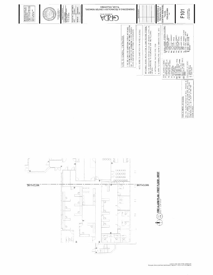
1. A legend sheet, match lines, site plan, north indication.
2. Clean architectural floor plans and site plans drawn to minimum 1/8-inch scale except as
otherwise noted hereinafter and a system riser diagram in 1/8-inch scale with a title block
on each drawing. Title block to contain name, address and phone number of Contractor,
Subcontractor name, location of work, project number, date, revision number and date,
designer’s name, reviewers name, drawing title and drawing number.
3. Sequence of Operations to include a detailed description of the operation of each system
function for all possible alarm conditions.
4. Point to point wiring diagrams.
5. Control panel 120 volt power sources including panel location and identification, circuit
size and number.
6. Control panel wiring diagrams including all jumper and dip switch positions and their
functions or options.
7. Detailed wiring diagrams for all HVAC damper and shutdown circuits and AC power
shutdowns interfaced with the new gaseous suppression systems.
8. Address-specific programming matrix including a complete list of all proposed
alphanumeric descriptions and their associated point address and circuit number.
9. Riser diagram for all devices, appliances, auxiliary power supplies and all interfaced
circuits.

GRDA Engineering & Technology Center Remodel DCS#ID13032-5
Tulsa, OK
For Construction 212200 06/21/2013
Page 5 of 23
10. Supervisory and alarm current calculations for primary power and emergency battery
sizing.
11. Voltage drop calculations for notification circuits based on worse case system voltage of
20.4 vdc.
12. Device and appliance locations, conduit and wiring locations and routing, panel locations,
all equipment locations, mounting heights and mounting details for all equipment and
typical wiring diagrams for devices and appliances.
13. Pipe routing, nozzle locations and piping supports.
14. Manufacturers' literature, including data sheets and operating manuals on all system
equipment and system conductors. Literature shall include specification and description
of recommended supporting methods, enclosures or boxes, and wiring connections.
Where literature includes data for other devices or equipment not proposed for use on this
project, the equipment and material proposed shall be clearly identified. This shall
include, but not be limited to, the following:
a. Detectors
b. Manual discharge stations
c. Control panels
d. Addressable modules and relays
e. Release devices, including proof of control panel/release device compatibility
listing.
f. Alarm audible and visual devices
g. Agent storage cylinders
h. Pipe and fittings
i. Mounting brackets
j. Discharge nozzles
k. Abort stations
l. Piping isometrics
m. Wire
n. Signage
15. Computerized verification of flow calculations shall be submitted for the fixed gaseous
suppression systems and shall include the following data as a minimum:
a. Quantity of agent per nozzle
b. Type of nozzle
c. Pressure at nozzle (psi)
d. Nozzle body nominal pipe size (inches)
e. Number and size of cylinders
f. Total agent
g. Pipe size per pipe section
h. Pipe schedule per pipe section
i. Number, size and type of fitting per pipe section
j. Actual length per pipe section (feet)
k. Equivalent length per pipe section (feet)
l. Discharge time (seconds)
16. Under and over pressure venting calculations shall be submitted for the fixed gaseous
suppression systems if venting is required and shall include the following data as a
minimum:
a. Discharge time in seconds
b. Enclosure strength in pounds per square foot.
c. Vent free area required in square inches.

GRDA Engineering & Technology Center Remodel DCS#ID13032-5
Tulsa, OK
For Construction 212200 06/21/2013
Page 6 of 23
d. Expected maximum enclosure negative pressure.
e. Expected maximum enclosure positive pressure.
17. Six (6) copies of the transmittal of the permit application to the AHJ.
18. Six (6) copies each of all installation manuals.
19. Six (6) copies of a schedule of values to be the basis for all progress payment requests by
the Contractor
C. Forward in writing, to the Owner’s Fire Protection Consultant, any comments from the AHJ or
the Insurance Underwriter within five (5) working days after the receipt of their comments.
D. The Owner’s Fire Protection Consultant shall review for accuracy all submittals required to be
received by the Owner’s Fire Protection Consultant prior to equipment release or installation.
The Owner or the Owner’s Fire Protection Consultant shall not be responsible for any additional
costs resulting from replacement of equipment or materials not reviewed prior to installation.
1.10 PROJECT RECORD DOCUMENTS
A. Prior to final payment for the gaseous suppression systems and the beginning of the warranty
period, submit the following completed project record documents to the Owner:
1. Copies of all reports for tests and inspections as required by the AHJ and as specified.
2. All permits and licenses required to be in the possession of the Owner by the AHJ.
3. Record drawings of the complete installation to include, but not be limited to, the
information required for the shop drawings. All information shall accurately show the
completed installation. Record drawings of the floor plans shall be AutoCAD 2007
generated.
4. Original warranty documents including, but not limited to, those of the Equipment
Manufacturer Warranty documents shall reference and be binding to the warranty
provisions specified.
5. Copies of all site specific programming on electronic media suitable for downloading into
the fire alarm system.
B. Upon completion of construction, submit six (6) sets of equipment warranties and six (6) sets of
operations and maintenance instructions to the Owner.
C. Prior to final payment for the fire alarm system, acceptance of the system as complete, and the
beginning of the warranty period, submit to the Owner’s Fire Protection Consultant a copy of
the transmittal to the Owner for all final complete project record documents.
1.11 OPERATION AND MAINTENANCE MANUAL
A. The contractor shall provide the Owner’s Fire Protection Consultant with a loose-leaf manual
containing:
1. A detailed description of the system.
2. A detailed description of routine maintenance required or recommended or as would be
provided under a maintenance contract including a maintenance schedule and detailed
maintenance instructions for each type of device installed.
3. Manufacturer’s data sheets and installation manuals/instructions for all equipment
installed.

GRDA Engineering & Technology Center Remodel DCS#ID13032-5
Tulsa, OK
For Construction 212200 06/21/2013
Page 7 of 23
4. A list of recommended spare parts.
5. Service directory which includes the main 24-hour emergency service number and at
least three alternate numbers which are monitored on a 24- hour basis.
6. Small scale (11 inches by 17 inches) contractor record drawings of the system.
7. A detailed description of the operation of the system, including operator responses. The
approved sequence of operation shall be placed in, or adjacent to, the operator’s control
panel.
8. A printout copy of all system programming, listing all addresses within the system (both
active and spare), address functions, and program activities of control relays.
B. Prior to acceptance of the work by the Owner’s Fire Protection Consultant, Operation and
Maintenance manuals shall be delivered to the Owner’s Fire Protection Consultant.
C. Test Record.
1. The date and time of each test.
2. A reference set of contractor record drawings, numerically identifying the individual
components and circuits tested, test locations, and indicating the measured sound level
recorded during alarm conditions.
3. A description of each test performed.
4. A checklist of each device and circuit tested, indicating the results of each test.
5. The names and signatures of the individuals conducting and witnessing each test.
6. System certification and documentation of system testing by the Contractor shall be
submitted to the Owner’s Fire Protection Consultant for review and approval at least 14
calendar days prior to the final acceptance test.
1.12 SYSTEM DESCRIPTION AND OPERATION
A. The suppression systems shall be fixed total flooding, FM-200 (Heptafluoropropane) or Novec
1230 clean agent, fire suppression systems designed to provide a uniform concentration
throughout the protected areas.
1. The amount of agent to be provided shall be the amount required to obtain a uniform
(minimum) concentration required by the design manual for ten (10) minutes. The
required minimum design concentration shall be 7% by volume for FM-200 or 4.2% by
volume for Novec 1230 at the normal room or area ambient temperature. Such factors as
energized electrical equipment, unclosable openings (if any), "rundown" time of fans,
time required for dampers to close (and requirements for any additional dampers),
enclosure pressure relief venting and any other feature of the facility that could affect
concentration shall be taken into consideration and the design concentration increased as
required.
2. The discharge time required to achieve 95% of the minimum design concentration for
flame extinguishment based on a 20% safety factor shall be as close to 10 seconds as
possible in order to limit or reduce the possible enclosure pressure differences. Discharge
times shall be between 9 and 10 seconds.
3. The Contractor shall inspect the enclosures and determine if the enclosures have the
structural strength and integrity necessary to contain the agent discharge. If the developed
pressures present a threat to the structural strength of the enclosures, venting shall be
provided to prevent excessive pressures. Venting systems, where provided, shall be
designed to be failsafe. In the event venting systems are determined not to be required,
the Contractor shall provide a written report, reviewed and signed by the system

GRDA Engineering & Technology Center Remodel DCS#ID13032-5
Tulsa, OK
For Construction 212200 06/21/2013
Page 8 of 23
equipment manufacturer, detailing the enclosure under and over pressure engineering
design analysis.
4. Parameters referenced herein shall be verified with applicable codes and standards.
1.13 SEQUENCE OF OPERATION
A. Activation of the system shall be via cross zoned ionization and photoelectric type smoke
detection for the main room areas. In raised floor cavities, photoelectric type detectors shall be
alternated throughout the protected areas with the system requiring two (2) detectors in alarm
prior to automatic agent release.
1. Activation of any single smoke detector in any detection zone shall:
a. Cause a first-stage alarm.
b. Energize a lamp on the activated detector and control panel.
c. Activate audible (bells) devices in the affected areas.
d. Release magnetic door holders to non-gaseous system protected rooms adjacent to
protected areas.
e. Transmit a general alarm to the building’s fire alarm system.
Note: The building fire alarm system shall activate all building fire alarm system
audible and visual appliances except for those located in the gaseous suppression
zone in alarm. If no gaseous suppression zones are in alarm, all building fire alarm
system audible and visual appliances shall activate. In the event the fire alarm sys-
tem is in alarm prior to a gaseous suppression system entering an alarm state and
all fire alarm system appliances are activated, the fire alarm system appliances
shall turn off in the gaseous suppression zone if the zone enters an alarm state.
2. Activation of a second (cross zoned) smoke detector shall:
a. Cause a second-stage (pre-discharge) alarm to operate.
b. Operate auxiliary contacts for air conditioning HVAC unit shutdown and closing
of automatic room dampers.
c. Initiate a programmable 60 second time delay (agent release).
d. Activate audible and visual (horns and strobes) devices in the affected areas.
e. Activate visual (rotating beacons) devices in the corridors.
f. Open the enclosure vent dampers if provided.
3. Upon completion of the time delay, the system shall:
a. Energize control solenoid for discharge agent into protected area.
b. Cause a discharge alarm to be activated.
c. Shunt trip AC power circuits to mechanical units located within the protected area
or in the ceiling cavity above the protected area via discharge pressure switch
contacts.
d. Continue to activate visual and audible alarms.
e. Transmit a discharge signal to the building’s fire alarm system.
f. Close enclosure vent dampers 15 seconds after discharge.
1.14 AUXILIARY COMPONENTS
A. Double action manual releasing stations shall release the agent after a 10 second time delay and
cause all audible/visual alarms to activate. In addition, activation of the manual releasing
stations shall immediately close HVAC and room dampers, open vent dampers and shutdown of

GRDA Engineering & Technology Center Remodel DCS#ID13032-5
Tulsa, OK
For Construction 212200 06/21/2013
Page 9 of 23
air conditioning units via power circuits. Enclosure vent dampers shall close 15 seconds after
discharge
B. Abort stations shall, when operated, interrupt the discharge of the agent. The abort stations shall
be momentary devices (dead-man) requiring constant pressure to maintain contact closure. After
release of abort station, a ten second time delay shall be provided prior to system discharge.
Manual Releasing Station activation shall override any abort station. Abort station operation
shall be per FM guidelines.
C. Addressable monitor modules shall be provided to monitor the suppression system general
alarm, discharge alarm and trouble conditions through the building fire alarm system.
D. A supervised maintenance lock-out switch shall be used to electrically disconnect each fire
suppression system release circuit during routine maintenance. The lock–out switch shall be a
key operated switch. A separate lock-out switch shall be provided for each zone.
PART 2 - PRODUCTS
2.1 GENERAL
A. Materials and equipment shall be of a single manufacturer. The name of the manufacturer and
the serial numbers shall appear on all major components.
B. All equipment and devices used shall be listed in both the UL Fire Equipment Directory and the
Factory Mutual Approval Guide.
C. Acceptable system manufacturers are Ansul and Kidde-Fenwal. No other equipment
manufacturers will be considered.
2.2 GENERAL MATERIALS – ELECTRICAL
A. All electrical enclosures, raceways and conduits shall be provided and installed in accordance
with applicable codes and intended use and contain only those electrical circuits associated with
the fire detection and control system and shall not contain any circuit that is unrelated to the
system.
B. Unless specifically provided otherwise in each case, all conductors shall be enclosed in rigid or
thin wall steel conduit, as conditions dictate.
C. Each gaseous system zone shall have a separate, dedicated raceway system.
D. Any conduit or raceway exposed to weather or other similar conditions shall be properly sealed
and installed to prevent damage. Provisions for draining and drying shall be employed.
E. NEMA rating and electrically hazardous classifications shall be observed and any equipment or
materials installed must meet or exceed the requirements of service.

GRDA Engineering & Technology Center Remodel DCS#ID13032-5
Tulsa, OK
For Construction 212200 06/21/2013
Page 10 of 23
F. Any wiring shall be of the proper size to conduct the circuit current but shall not be smaller than
#18 AWG unless otherwise specified for a given purpose. Wire that has scrapes, nicks, gouges
or crushed insulation shall not be used. The use of aluminum wire is strictly prohibited.
G. Direct wire splices are not permitted except for terminations where pigtails are furnished with
the device being connected and the device being connected is not factor equipped with a
terminal strip or screw type terminations.
H. All wire terminations shall be made with crimp terminals unless the device at the termination is
designed for bare wire terminations.
I. White colored wire shall be used exclusively for the identification of the neutral conductor of an
alternating current circuit.
J. Green colored wire shall be used exclusively for the identification of the earth ground conductor
of an AC or DC circuit.
K. All electrical circuits shall be numerically tagged with suitable devices at the terminating point
and/or splice. All circuit numbers shall correspond with the installation drawings.
L. All wiring and raceways shall be concealed and equipment mounted to walls or ceilings shall be
flush or semi-flush mounted except for the raceways and equipment located in electrical or
mechanical rooms.
2.3 CONTROL SYSTEMS – GENERAL
A. All control systems shall be UL Listed or FM approved. Control systems not conforming to UL
864 will not be acceptable. Control systems shall be utilized with listed or approved compatible
operating devices and shall be capable of providing the following features:
1. Ground fault indication
2. Supervised detection circuit(s)
3. Supervised alarm notification circuit(s)
4. Supervised release circuit(s)
5. Supervised manual release station circuit (if applicable)
6. Supervised primary power circuit
7. Alarm overrides trouble logic
8. Battery standby
9. Front panel indicating lamps (LEDs)
10. Key lock steel enclosure
11. Programmable time delay
12. Programmable detection logic
13. Prioritized trouble logic
14. Microprocessor based logic
2.4 GASEOUS SYSTEM CONTROL PANEL
A. The Gaseous System Control Panels shall contain a microprocessor based Central Processing
Unit (CPU). The CPU shall communicate with and control the following types of equipment

GRDA Engineering & Technology Center Remodel DCS#ID13032-5
Tulsa, OK
For Construction 212200 06/21/2013
Page 11 of 23
used to make up the system: intelligent detectors, addressable modules, notification appliances,
annunciators, and other system controlled devices.
B. Gaseous Suppression Zones shall each have a separate and dedicated control panel.
C. System Capacity and General Operation.
1. The system shall include Form-C alarm and trouble relays rated at a minimum of 2.0
amps @ 30 VDC. It shall also include Class A programmable notification appliance
circuits. Notification appliance circuits shall be wired for Class A operation.
2. All programming or editing of the existing program in the system shall be achieved
without special equipment and without interrupting the alarm monitoring functions of the
control panel.
3. The control panel shall provide the following features:
a. Drift Compensation to extend detector accuracy over life.
b. Sensitivity Test meeting requirements of NFPA 72
c. Maintenance Alert to warn of excessive smoke detector dirt or dust accumulation.
d. Alarm Verification with verification counters.
e. Cross Zoning with the capability of counting two detectors in alarm and two
software zones in alarm.
f. March time and temporal coding options.
g. Walk Test with check for two detectors set to same address.
D. Display.
1. The display shall provide all the controls and indicators used by the system operator and
may also be used to program all system operational parameters.
2. The display shall include status information and custom alphanumeric labels for all
intelligent detectors, addressable modules, and software zones.
3. The display shall provide an 80-character back-lit alphanumeric Liquid Crystal Display
(LCD). It shall also provide Light-Emitting-Diodes (LEDs), that will indicate the status
of the following system parameters: AC POWER, SYSTEM ALARM, SYSTEM
TROUBLE, SIGNAL SILENCED, and SUPERVISORY.
4. The display shall provide a key touch pad with control capability to command all system
functions, entry of any alphabetic or numeric information, and field programming. Two
different password levels shall be provided to prevent unauthorized system control or
programming.
5. The display shall include the following operator functions: SIGNAL SILENCE, RESET,
DRILL, and ACKNOWLEDGE.
E. Signaling Line Circuit (SLC).
1. The SLC interface shall provide power to and communicate with intelligent detectors and
modules. This shall be accomplished over a single SLC loop and shall utilize Class A
wiring. Each releasing zone shall be served by a separate dedicated SLC circuit.
2. The loop interface board shall receive analog information from all intelligent detectors
that shall be processed to determine whether normal, alarm, or trouble conditions exist
for each detector. The software shall automatically maintain the detector's desired
sensitivity level by adjusting for the effects of environmental factors, including the
accumulation of dust in each detector. The analog information shall also be used for
automatic detector testing and for the automatic determination of detector maintenance
requirements.
3. The detector software shall meet NFPA 72 requirements and be certified by UL as a
calibrated sensitivity test instrument.

GRDA Engineering & Technology Center Remodel DCS#ID13032-5
Tulsa, OK
For Construction 212200 06/21/2013
Page 12 of 23
F. All interfaces and associated equipment are to be protected so they will not be affected by
voltage surges or line transients consistent with UL standard 864.
G. Enclosures.
1. The control panel shall be housed in a UL listed cabinet suitable for semiflush mounting.
Cabinet and front shall be corrosion protected, given a rust-resistant prime coat, and
manufacturer's standard finish.
2. The door shall provide a key lock and include a glass or other transparent opening for
viewing of all indicators.
H. Power Supply.
1. The power supply shall operate on 120 VAC, 60 Hz, and shall provide all necessary
power for the control panel.
2. It shall provide a minimum of 3.0 amps of usable notification appliance power.
3. It shall provide a battery charger for minimum 48 hour recharge of standby batteries.
I. Field Wiring Terminal Blocks.
1. For ease of service, all panel I/O wiring terminal blocks shall be the removable, plug-in
type and have sufficient capacity for 18 to 12 AWG wire.
J. Operator Controls.
1. Acknowledge Switch:
a. Activation of the control panel acknowledge switch in response to new alarms
and/or troubles shall silence the local panel piezo electric. If multiple alarm or
trouble conditions exist, depression of this switch shall advance the LCD display to
the next alarm or trouble condition.
b. Depression of the acknowledge switch shall also silence all remote annunciator
piezo sounders.
2. Signal Silence Switch: Activation of the signal silence switch shall cause all programmed
alarm notification appliances and relays to return to the normal condition after an alarm
condition. The selection of notification circuits and relays that are silenceable by this
switch shall be fully field programmable within the confines of all applicable standards.
3. System Reset Switch: Activation of the system reset switch shall cause all electronically-
latched initiating devices, appliances or software zones, as well as all associated output
devices and circuits to return to their normal condition.
4. Drill (Evacuate) Switch. The drill switch shall activate all notification appliance circuits.
The drill function shall latch until the panel is silenced or reset.
5. Release Circuit Disconnect Switch. The disconnect switch shall disconnect the release
solenoid. Placing the disconnect switch in the disconnect position shall cause a system
trouble. The switch shall be a key operated switch or located within a locked enclosure.
K. Field Programming.
1. The system shall be programmable, configurable and expandable in the field without the
need for special tools or electronic equipment and shall not require field replacement of
electronic integrated circuits.
2. All field defined programs shall be stored in non-volatile memory.
3. The programming function shall be enabled with a password that may be defined
specifically for the system when it is installed. Two levels of password protection shall be
provided in addition to a key-lock cabinet. One level is used for status level changes

GRDA Engineering & Technology Center Remodel DCS#ID13032-5
Tulsa, OK
For Construction 212200 06/21/2013
Page 13 of 23
such as zone disable or manual on/off commands. A second (higher-level) is used for
actual change of program information.
4. Program edit shall not interfere with normal operation and fire protection. If a fire
condition is detected during programming operation, the system shall exit programming
and perform fire protection functions as programmed.
5. A special program check function shall be provided to detect common operator errors.
L. Specific System Operations.
1. Smoke Detector Sensitivity Adjust: Means shall be provided for manually adjusting the
sensitivity of any or all analog intelligent smoke detectors in the system from the system
keypad. Sensitivity range shall be within the allowed UL window.
2. Point Disable: Any device in the system may be Enabled or Disabled through the system
keypad.
3. System Status Reports: Upon command from a system operator, a status report will be
generated listing all system status.
M. Release Circuits
1. Release circuits shall be wired for Class B operation.
N. Batteries.
1. Batteries shall be 12 volt, Gel-Cell type (two required).
2. Batteries shall have sufficient capacity to power the system for not less than 24 hours in
standby plus 15 minutes of alarm upon a normal AC power failure.
3. Batteries are to be completely maintenance free. No liquids are required. Fluid level
checks, refilling, spills and leakage shall not be accepted.
2.5 SURGE PROTECTION
A. Provide 120 volt AC surge protectors for each gaseous system control panel AC power circuit.
AC surge protectors shall be mounted in a separate enclosure above the accessible ceiling at
each control panel location. Surge protectors shall not be mounted within the control panels.
B. Acceptable surge protectors are EDCO HSP121BT1 or equivalent.
2.6 ADDRESSABLE MANUAL RELEASE STATION
A. Addressable manual release station shall use a key operated test-reset lock and shall be designed
so that after actual emergency operation, they cannot be restored to normal use except by the
use of a key.
B. All operated stations shall have a positive, visual indication of operation and utilize a key-type
reset.
C. Manual stations shall be metal with clearly visible operating instructions provided on the cover.
The words “Fire Suppression System Release” or similar verbiage shall appear on the front of
the stations. All gaseous suppression system manual stations shall be identical and shall be of a
different type or style as the manual pull stations utilized for the fire alarm systems.
D. Stations shall be suitable for semi-flush mounting.

GRDA Engineering & Technology Center Remodel DCS#ID13032-5
Tulsa, OK
For Construction 212200 06/21/2013
Page 14 of 23
E. Operation shall require two (2) actions.
F. Manual Release Stations shall be provided at each exit of the protected area and shall, when
activated, cause total system release after a 10 second time delay.
G. Manual stations shall be installed at 48 inches above the finished floor to the operating
mechanism.
H. All gaseous system manual pull stations shall be provided with a clear protective cover which
protects the station from inadvertent or accidental activation. Acceptable cover is STI-1100
Stopper II, without alarm and without operating nomenclature on cover other than “Lift Here”.
2.7 SMOKE DETECTORS
A. Detectors shall be intelligent and addressable, and shall be connected to the release control
panel signaling line circuits.
B. Smoke detectors shall use the ionization or photoelectric (light-scattering) principals to measure
smoke density and shall, on command from the control panel, send data to the panel
representing the analog level of smoke density.
C. Addressable smoke detectors shall provide an alarm and communication LED. The LED shall
flash under normal conditions indicating that the detector is operational and in regular
communication with the control panel. The LED shall be placed into steady illumination by the
control panel indicating that an alarm condition has been detected. If required, the flashing
mode operation of the detector LED shall be optional through the system field program. An
output connection shall also be provided in the base to connect an external remote alarm LED.
D. Smoke detector sensitivity shall be set through the control panel and shall be adjustable in the
field through the field programming of the system. Sensitivity may be automatically adjusted by
the panel on a time-of-day basis.
E. Using software in the control panel, detectors shall automatically compensate for dust
accumulation and other slow environmental changes that may affect their performance. The
detectors shall be listed by UL as meeting the calibrated sensitivity test requirements of NFPA
Standard 72.
F. The detectors shall be and shall include a separate twist-lock base with tamper-proof feature.
G. The detectors shall provide a test means whereby they will simulate an alarm condition and
report that condition to the control panel. Such a test may be initiated at the detector itself (by
activating a magnetic switch) or initiated remotely on command from the control panel.
H. Smoke detectors shall be installed at no more than 400 square feet (37 m2) of coverage per
detector or as indicated on the project drawings. Each protected room or area shall be provided
with a minimum of two detectors for cross-zoning purposes.

GRDA Engineering & Technology Center Remodel DCS#ID13032-5
Tulsa, OK
For Construction 212200 06/21/2013
Page 15 of 23
2.8 ADDRESSABLE DRY CONTACT MONITOR MODULE
A. Addressable monitor modules shall be provided to connect conventional alarm initiating devices
to one of the control panel signaling line circuit (SLC) loops.
B. The monitor module shall mount in a 4-inch square, 2-1/8" deep electrical box. Monitor
modules serving equipment in finished areas shall be located above the ceiling.
C. The IDC zone may be wired for Class B operation. An LED shall be provided that shall flash
under normal conditions indicating that the monitor module is operational and in regular
communication with the control panel.
2.9 MAINTENANCE LOCK-OUT SWITCH
A. This switch shall be key operated allowing removal of the key in either the "Normal" or "Lock-
Out" position. A red indicator lamp shall be included on the switch assembly to be illuminated
when in the "Lock-Out" position. The control panel is to indicate a trouble condition when in
the "Lock-Out" position.
B. The switch shall include one (1) set of normally open and one (1) set of normally closed
contacts rated at 28 VDC @ 1.1 amp make/break or 6 amp continuous carry.
C. The terminal connections shall be of the screw type.
D. Maintenance lock-out switches shall be flush mounted.
E. The inert gas maintenance lock-out switches shall be keyed alike for each zone.
F. Maintenance lock-out switches shall be provided adjacent to the respective control panel.
G. The maintenance lock-out switch shall electrically disconnect the release solenoid or circuit.
The use of control panel enable or disable switch functions will not be an acceptable alternative
to the separate maintenance lock-out switch.
H. The maintenance lock-out switches shall be UL listed for use in fire alarm systems.
2.10 ABORT SWITCH
A. This switch shall be rated at 28 VDC @ 1.1 amp make/break or 6 amp continuous carry.
B. The terminal connections shall be of the screw type.
C. Abort stations shall be provided at each exit of the protected area and at each control panel.
D. This switch shall be a momentary contact "dead-man" type switch requiring constant pressure to
transfer one set of contacts. Clear operating instructions shall be provided at the abort switch.

GRDA Engineering & Technology Center Remodel DCS#ID13032-5
Tulsa, OK
For Construction 212200 06/21/2013
Page 16 of 23
2.11 NOTIFICATION APPLIANCES
A. Provide notification appliances within each protected area to indicate both a first-stage and
second-stage alarm. Provide notification appliances outside each protected area to indicate
second-stage alarm.
B. Fire alarm bells shall be provided both within each protected area, adequately spaced for proper
audible coverage to indicate a first-stage alarm.
1. Bells shall be a minimum 4-inch diameter, 24 VDC, capable of producing an alarm signal
of not less than 85 dB at 10 feet. Bells shall be supervised by the appropriate notification
appliance circuit.
2. Bells shall be listed to UL Standard 464.
C. Fire alarm horn/strobe combination units shall be provided within each protected area,
adequately spaced for proper coverage to indicate a secondstage alarm.
D. Horns shall be 24 VDC, and capable of producing an alarm signal of not less than 85 dB at 10
feet.
E. Horns shall be listed to UL Standard 464.Strobes shall be a minimum 15 candela rating and
listed to UL Standard 1971.
F. Horn/strobes shall be supervised by the appropriate notification appliance circuit.
G. Rotating beacons shall be provided in the corridors near door to each area to indicate a second
stage alarm.
H. Beacons shall be 120 VAC or 24VDC.
I. Beacons shall be red in color and shall flash at a rate of 60 times per minute.
J. Beacons shall utilize a parabolic reflector which rotates around an incandescent light source.
K. Beacons shall be recessed mounted to the corridor ceiling.
L. Permanent engraved signs or identification on each device shall be provided to indicate its
function.
2.12 HVAC SHUTDOWN, DAMPER CONTROL, DOOR RELEASE AND AC POWER SHUNT
TRIP
A. Provide shut down interface for each HVAC unit located within the protected area or ceiling
cavity above the protected area for all units which serve the protected area and for all units
serving adjacent areas. Provide shut down interface for each HVAC unit located outside of the
protected area for all units which serve the protected area.
B. Provide door release control for each door indicated on the project drawings. Power for door
release control shall be from 120 volt AC power derived from the building EM power source. A
minimum of two 120 volt 20 ampere EM circuits shall be provided for control of the door
release circuits. Each zone shall have a minimum of one each dedicated EM circuit for door
release power.

GRDA Engineering & Technology Center Remodel DCS#ID13032-5
Tulsa, OK
For Construction 212200 06/21/2013
Page 17 of 23
C. Provide shunt trip of AC power for all HVAC units located within the protected area or ceiling
cavity above the protected area whether or not they serve the protected area. Shunt trip circuits
shall be controlled by system discharge pressure switches. Power for shunt trip circuits shall be
from 120 volt AC power derived from the building EM power source. A minimum of four 120
volt 20 ampere EM circuits shall be provided for control of the shunt trip circuits. Each zone
shall have a minimum of one each dedicated EM circuit for shunt trip power. Slave relays shall
be provided where required to provide adequate relay contact inductive ampacity. Relay
contacts shall be normally open and shall close to initiate the shunt trip sequence. The EM
power sources serving the shunt trip circuits shall be monitored for loss of power by the
respective gaseous system control panel.
D. Provide interface for control of all dampers serving HVAC equipment located within the
protected area or ceiling cavity above the protected area to prevent agent leakage to all adjacent
non-protected spaces.
E. Provide for operating sequences for HVAC shutdown, damper control and shunt trip.
F. Refer to the mechanical drawings for locations of HVAC units and dampers.
G. Refer to the electrical drawings for locations of AC power shunt trip circuits.
2.13 MAGNETIC DOOR HOLDERS
A. Provide magnetic door holders for the rooms indicated on the project drawings.
B. Magnetic door holders shall be powered by 120 volts AC and shall be controlled by the gaseous
suppression and fire alarm systems.
2.14 SUPPRESSION SYSTEM
A. A total flooding fire suppression system shall be of the engineered, permanently piped, fixed
nozzle type with all pertinent components.
B. All agent storage cylinders shall be centrally located as vertical, free-standing cylinders with
wall and/or floor mounted retaining brackets. A common manifold shall be employed for
multiple cylinders.
C. On multiple cylinder arrangements one cylinder shall be designated as the pilot cylinder and
employ a restorable electric actuator. All remaining cylinders shall be pneumatically operated
from the agent discharge of the pilot cylinder into the manifold. The electric actuator shall be
easily removable to facilitate testing.
D. Storage cylinders shall be located in the areas indicated on the project drawings.
E. Manifolded cylinders shall employ a flexible discharge hose to facilitate tank installation and
system maintenance. Each cylinder on a manifold shall also include an agent check valve
installed to the manifold inlet.

GRDA Engineering & Technology Center Remodel DCS#ID13032-5
Tulsa, OK
For Construction 212200 06/21/2013
Page 18 of 23
2.15 PIPE MATERIAL – SUPPRESSION SYSTEM
A. System piping shall be of non-combustible materials having physical and chemical
characteristics such that its integrity under stress can be predicted with reliability.
B. As a minimum, piping materials shall be black steel pipe conforming to ASTM A-53A ERW or
ASTM A-106A seamless.
C. Under no conditions shall ordinary cast iron pipe, steel pipe conforming to ASTM A-120 or
ASTM A-53/A-120 be used.
D. As a minimum, fittings shall be black, 300 lb. class fittings conforming to ANSI B-16.3.
Ordinary cast iron fittings shall not be used.
E. All piping shall comply with NFPA 2001 and the manufacturer’s installation requirements.
F. Piping shall be installed in accordance with good commercial practice and NFPA 2001, securely
supported with UL Listed hangers and arranged with close attention to the design layout since
deviations may alter the design flow performance as calculated.
G. Piping shall be bracketed and braced within 12" (.3 m) of all discharge nozzles.
H. All piping shall be reamed, blown clear and swabbed with appropriate solvent to remove mill
varnish and cutting oils before assembly. The Contractor shall notify the Owner or Owner’s Fire
Protection Consultant prior to the pipe cleaning in the event either party elects to observe the
process.
I. Multi-outlet fittings, other than tees, shall not be permitted.
J. Assembly of all joints shall conform to the appropriate standards. Threaded pipe joints shall
utilize Teflon tape applied to the male threads only.
2.16 EXTINGUISHING AGENT
A. The agent shall be FM-200 or 3M NOVEC 1230 Fire Protection Fluid
2.17 STORAGE CYLINDERS
A. Cylinder assemblies shall be of steel construction. Each cylinder shall be equipped with a
pressure seat type valve and gauge.
B. Filling of the cylinder assembly shall be by an authorized systems distributor in conjunction
with a factory authorized agent filling station. Initial filling and recharge shall be performed in
accordance with the manufacturer's established procedures and shall not require replacement
components for normal service.
C. Agent storage cylinders shall be located in the areas identified on the project drawings.
Spherical type storage cylinders will be permitted in the ceiling cavity in the locations indicated
on the project drawings.

GRDA Engineering & Technology Center Remodel DCS#ID13032-5
Tulsa, OK
For Construction 212200 06/21/2013
Page 19 of 23
D. Where spherical type storage cylinders are utilized, they shall be securely mounted and braced
in accordance with NFPA 2001 and the manufacturer’s instructions. Piping for ceiling cavity
located cylinders shall be concealed within the wall cavities where the cylinder provides agent
for the floor cavities.
2.18 VALVE ACTUATORS
A. Electric valve actuators shall be of brass construction and stackable design with swivel
connections to allow removal of actuators for maintenance or testing.
B. Operation of actuators shall not require replacement of components. Electroexplosive devices
may be used to actuate the release of spherical cylinders located in the ceiling cavities.
C. Electric actuators shall be the magnetic latch, continuous duty type for 24 VDC operation.
D. Actuation devices shall be UL listed and/or FM approved for use with the system.
E. Actuators shall not be equipped with a manual release feature.
F. Release circuit wiring shall be in a separate dedicated raceway for each zone. The release circuit
raceway shall not contain any other wiring other than the release circuit wiring.
2.19 DISCHARGE HOSE AND CHECK VALVE
A. When manifolding, all cylinder assemblies shall include a flexible discharge hose and check
valve for connection to the manifold inlet.
B. All hose/check valves shall be UL listed and/or FM approved.
2.20 DISCHARGE NOZZLES
A. Discharge nozzles shall be of two-piece construction and sized to provide flow rates in
accordance with system design flow calculations.
B. Orifice(s) shall be machined in the nozzle body to provide a horizontal discharge pattern based
upon the approved coverage arrangements.
C. Nozzles shall be permanently marked with the manufacturer's part number. The nozzles shall be
threaded directly to the discharge piping without the use of special adapters.
D. Nozzle piping shall be finished with trim rings at the suspended ceiling.
E. Nozzles shall be UL listed and/or FM approved.
F. Ceiling tiles located within a 10 foot radius of each discharge nozzle shall be clipped in place.

GRDA Engineering & Technology Center Remodel DCS#ID13032-5
Tulsa, OK
For Construction 212200 06/21/2013
Page 20 of 23
2.21 CONDUCTORS AND CONDUIT
A. All system wiring shall be installed in a UL listed metal conduit or raceway.
B. Wiring shall be in accordance with NEC Article 760 and as recommended by the manufacturer
of the system. Number and size conductors shall be as recommended by the system
manufacturer, but not less than 18 AWG for initiating device circuits and 12 AWG for
notification appliance circuits.
C. All new conductor runs shall be continuous between devices, without splices. All connections
shall be to terminal blocks or floating terminal strips located inside junction boxes or panels.
Wires connected together shall have the same color insulation. All connections shall be
accessible for inspection and servicing and shall be clearly identified on the contractor record
drawings.
D. New wire and cable shall be sized, twisted and shielded as recommended by the fire alarm
system manufacturer and Article 760 of the NEC.
E. All new conduits shall be grounded by approved ground clamps or other means in conformance
with the Electrical Code.
F. All electrical enclosures, raceways and conduits shall contain only those electrical circuits
associated with the fire detection and alarm system and shall not contain any circuit that is
unrelated to the system.
G. All interior wiring shall be enclosed by EMT conduit, 3/4 inch minimum. All exterior conduit,
terminal cabinets and fittings shall be waterproof.
H. New wire that has scrapes, nicks, gouges or crushed insulation shall not be used.
I. The use of aluminum wire is prohibited.
J. All new electrical circuits shall be numerically tagged at both ends with durable tags, such as
Brady tags. The circuit number system shall be indicated on the contractor record drawings.
K. All system conductors shall be solid copper. The use of multi-stranded conductors is prohibited.
L. All end-of-line resistors shall be mounted on terminal blocks and shown on Contractor’s record
drawings.
M. T-Tapping of the SLC wiring will be allowed only where wiring is terminated on terminal strips
rated for the number of conductors terminated.
2.22 WARRANTY
A. All system components furnished under this contract shall be guaranteed against defect in
design, material and workmanship (including labor) for the full warranty time which is standard
with the manufacturer and/or supplier, but not less than one (1) year from the date of the system
acceptance. In addition, the installing contractor must guarantee the systems against false
actuation or leakage due to faulty equipment, design or workmanship for a period of one (1)
year from final acceptance. In the event of agent leakage or system discharge from any of the

GRDA Engineering & Technology Center Remodel DCS#ID13032-5
Tulsa, OK
For Construction 212200 06/21/2013
Page 21 of 23
above condition, the installing contractor shall completely recharge and recondition the system
at no cost to the Owner.
2.23 EMERGENCY SERVICE
A. The Contractor shall provide emergency repair service for the system at no cost to the Owner,
within four hours of a request for such service by the Owner during the installation and
guarantee periods. This service shall be provided on a 24-hours per day seven days per week
basis.
B. Contractor shall respond to an emergency within 2 hours of receiving an emergency trouble
call.
PART 3 - EXECUTION
3.1 GENERAL
A. This installation shall be made in strict accordance with the specifications and applicable Codes
and Standards, including all local requirements.
B. The Contractor shall examine daily all areas in which the work will be performed on the day
prior to beginning work. The Contractor shall immediately report unsatisfactory working
conditions to the Owner’s Consultant for resolution. The Contractor shall not proceed with the
work until all unsatisfactory working conditions have been corrected.
C. It shall be the Contractor’s responsibility to inspect the job site and become familiar with the
conditions under which the work will be performed.
D. The Contractor shall be responsible for prior coordination of all work.
3.2 INSTALLATION
A. All holes made by the Contractor (including openings resulting from removal of existing
systems) in any wall, ceiling or floor shall be patched and painted by the Contractor, restoring
the walls, ceilings, and floors to their original condition, fire resistance, integrity and color. All
work shall be done in accordance with the requirements of the specifications.
B. All piping and conduit shall be installed at a height so as not to obstruct any portion of a
window, doorway, stairway or passageway and shall not interfere with the operation of any
existing mechanical or electrical equipment.
C. Pipe and conduit penetrations shall be firestopped utilizing an approved UL listed firestop
method, materials and detail.
D. Locations of all equipment, controls and system components are subject to the approval of the
Owner’s Fire Protection Consultant.

GRDA Engineering & Technology Center Remodel DCS#ID13032-5
Tulsa, OK
For Construction 212200 06/21/2013
Page 22 of 23
E. Exposed conduit, raceways, junction boxes, and other associated items related to the conduit
and piping network shall be provided with red bands every ten feet with junction box covers
painted red.
F. Devices, equipment and wiring installed in exterior locations shall be suitable for weatherproof
applications.
3.3 SYSTEM TESTS
A. The Contractor shall perform the following:
1. Arrange for system inspection and testing by a manufacturer’s certified representative.
2. Ensure the system is installed in accordance with the manufacturer’s recommendations,
UL listings and AHJ requirements.
3. 3. Is in proper working order.
B. System Inspection.
1. The completed installation shall be inspected by factory authorized and trained personnel.
The inspection shall include a full operational test of all components per the equipment
manufacturer's recommendations (excluding agent discharge).
2. All mechanical and electrical components shall be tested according to the manufacturer's
recommended procedure to verify system integrity.
3. Inspection shall include a complete checkout of the detection/control system and
certification of cylinder pressure. A written report shall be filed with the Owner.
4. The AHJ shall be notified by the Contractor and invited to witness the testing.
C. Acceptance Tests Control System.
1. Upon completion of the System Inspection phase, the Contractor shall perform and
document system tests as required by the NFPA 72 and 2001, and the Owner’s Fire
Protection Consultant. All acceptance tests shall be performed in the presence of the
Owner’s Fire Protection Consultant. At a minimum, test and demonstrate the following:
a. All conductors, including shielding conductors, shall be tested for continuity,
shorts to ground and shorts between pairs.
b. All indicating devices have been functionally tested.
c. All supervisory functions of each indicating device circuit shall be functionally
tested.
d. Receipt of all alarm and trouble signals, initiated during the course of the testing,
shall be verified at the control panel.
e. Correct labeling of all annunciation devices LED’s shall be verified.
f. Discharge piping system flow and pressure tests. In the event the existing piping
systems are reused, the existing piping systems shall also be tested.
g. Damper operation and HVAC shutdown.
2. A functional test shall be completed consisting of detection, release, alarm, accessories
related to the system, control unit and a review of the cylinders, piping, fittings, hangers
and cylinder pressure.
D. Enclosure Integrity Test
1. An enclosure integrity test (door fan test) shall be performed by the Contractor for each
protected area.
2. Testing shall be in accordance with NFPA 2001.

GRDA Engineering & Technology Center Remodel DCS#ID13032-5
Tulsa, OK
For Construction 212200 06/21/2013
Page 23 of 23
3. The Contractor shall provide all necessary labor, apparatus, and instrumentation for the
test.
4. Testing protocol shall be established by the Contractor and submitted for approval to the
Owner’s Fire Protection Consultant as described in these specifications.
5. If test results indicate a holding time of 10 minutes for the specified agent concentration
level was not attained, the Contractor shall determine the probable cause and notify the
Owner’s Fire Protection Consultant. At such time, the Owner and Owner’s Fire
Protection Consultant shall determine the appropriate course of action, if any.
E. Any additional tests required by the referenced codes, standards and criteria, and by the
Owner’s Fire Protection Consultant, and authorities shall be performed.
F. The Contractor shall provide at least five (5) working days notice for all tests.
3.4 SPURIOUS ALARMS
A. If the system experiences spurious or unexplained false alarms during the guarantee periods, the
Contractor shall be responsible for providing the necessary labor, material and technical
expertise to correct the problem to the satisfaction of the Owner.
3.5 PROGRAMMING
A. The Contractor shall provide all system programming, at no additional cost, required for the
system. This shall include, but not be limited to, all necessary programming for proper
operation in accordance with the specifications. Prior to final acceptance of the system, the
Owner’s Fire Protection Consultant may require modifications to the system program for
message descriptors. These changes shall be made at no additional cost.
3.6 TRAINING
A. Train not less than three Owner staff, with personal on the job instruction provided by
competent engineers representing the manufacturer.
B. Training shall include all system operational functions needed. This shall include, but will not
be limited to:
1. Alarm acknowledgment.
2. Interpretation of the scheme used to provide identifiers.
3. System reset.
4. Basic troubleshooting.
5. Control system operation
6. Trouble procedures
7. Abort procedures
8. Emergency procedures
9. Safety requirements
10. Demonstration of the system (excluding agent release)
END OF SECTION 212200