© aerospatiale matra-airbus 1999 page 1 bte/sy/avc - september 23 rd, 1999 airbus industrie data...
TRANSCRIPT
© Aerospatiale Matra-Airbus 1999 Page 1BTE/SY/AVC - September 23rd, 1999
Airbus IndustrieAirbus Industrie
DATA LINK INTEGRATION ON AIRBUS: AIM - FANS
Airbus Interoperable Modular - Future Air Navigation System
LONDON
September, 23rd 1999
© Aerospatiale Matra-Airbus 1999 Page 2BTE/SY/AVC - September 23rd, 1999
Airbus IndustrieAirbus Industrie Contents
Introduction
FANS (CNS/ATM) evolutions
Why FANS ?
What is FANS ?
CNS/ATM environments
Characteristics
Main steps
Airbus designObjectives
AIM-FANS
AIM-FANS steps
AIM-FANS architecture The ATSU (Air Traffic Services Unit)
Human Machine Interface
Experience gainedPre FANS
EOLIA / ProATN
Conclusion
Glossary
© Aerospatiale Matra-Airbus 1999 Page 3BTE/SY/AVC - September 23rd, 1999
Airbus IndustrieAirbus Industrie Introduction
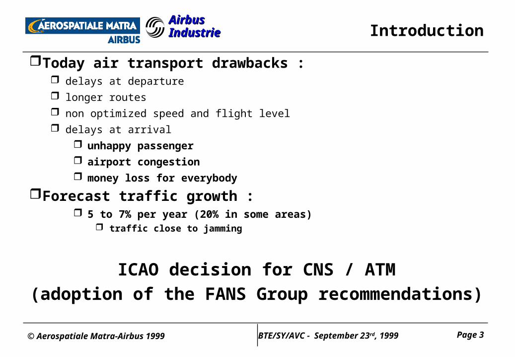
Today air transport drawbacks : delays at departure longer routes non optimized speed and flight level delays at arrival
unhappy passenger airport congestion money loss for everybody
Forecast traffic growth : 5 to 7% per year (20% in some areas)
traffic close to jamming
ICAO decision for CNS / ATM
(adoption of the FANS Group recommendations)
© Aerospatiale Matra-Airbus 1999 Page 4BTE/SY/AVC - September 23rd, 1999
Airbus IndustrieAirbus Industrie Introduction
FANS (Future Air Navigation System), or more accurately CNS/ATM (Communication, Navigation, Surveillance / Air Traffic Management) covers the main evolutions of the way the airspace will be used in the years to come.
Therefore, by definition, FANS (CNS/ATM) implementation is an evolutionary process that :
involves improvements to the airborne and ground systems to allow more efficient aircraft operations,
is centered on a better circulation of information between the airspace users (airlines, ...) and the airspace managers (Air Traffic Service providers).
Airbus Industrie is committed to support FANS (CNS/ATM) developments. Thus, it is preparing its family of fly-by-wire aircraft to take advantage of the evolutions of airspace management in a flexible and evolutive manner.
© Aerospatiale Matra-Airbus 1999 Page 5BTE/SY/AVC - September 23rd, 1999
Airbus IndustrieAirbus Industrie
FANS (CNS/ATM) evolutions
© Aerospatiale Matra-Airbus 1999 Page 6BTE/SY/AVC - September 23rd, 1999
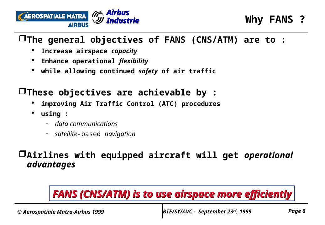
Airbus IndustrieAirbus Industrie Why FANS ?
The general objectives of FANS (CNS/ATM) are to : Increase airspace capacity Enhance operational flexibility while allowing continued safety of air traffic
These objectives are achievable by : improving Air Traffic Control (ATC) procedures
using :
data communications satellite-based navigation
Airlines with equipped aircraft will get operational advantages
FANS (CNS/ATM) is to use airspace more efficientlyFANS (CNS/ATM) is to use airspace more efficiently
© Aerospatiale Matra-Airbus 1999 Page 7BTE/SY/AVC - September 23rd, 1999
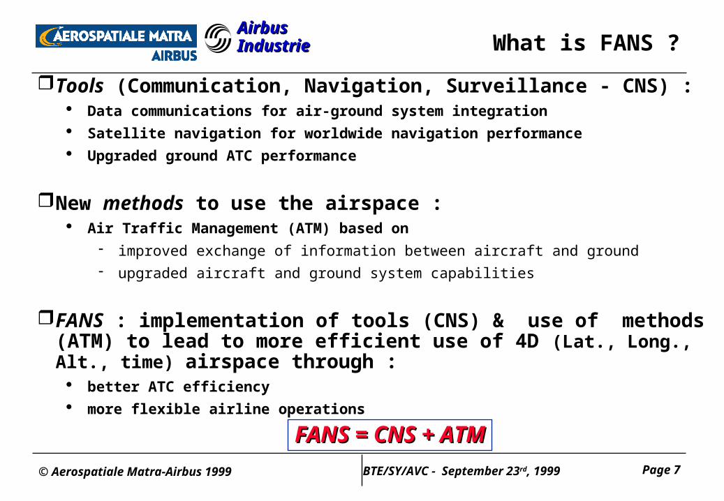
Airbus IndustrieAirbus Industrie What is FANS ?
Tools (Communication, Navigation, Surveillance - CNS) : Data communications for air-ground system integration
Satellite navigation for worldwide navigation performance
Upgraded ground ATC performance
New methods to use the airspace : Air Traffic Management (ATM) based on
improved exchange of information between aircraft and ground
upgraded aircraft and ground system capabilities
FANS : implementation of tools (CNS) & use of methods (ATM) to lead to more efficient use of 4D (Lat., Long., Alt., time) airspace through :
better ATC efficiency
more flexible airline operationsFANS = CNS + ATMFANS = CNS + ATM
© Aerospatiale Matra-Airbus 1999 Page 8BTE/SY/AVC - September 23rd, 1999
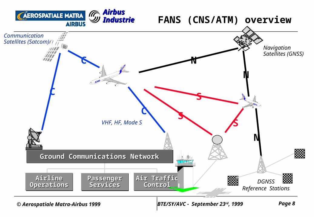
Airbus IndustrieAirbus Industrie FANS (CNS/ATM) overview
N
N
N
S
SS
C
C
CVHF, HF, Mode S
Communication Satellites (Satcom)
Navigation Satellites (GNSS)
AirlineAirlineOperationsOperations
AirlineAirlineOperationsOperations
Air TrafficAir TrafficControlControl
Air TrafficAir TrafficControlControl
PassengerPassengerServicesServices
PassengerPassengerServicesServices
Ground Communications NetworkGround Communications NetworkGround Communications NetworkGround Communications Network
DGNSSReference Stations
© Aerospatiale Matra-Airbus 1999 Page 9BTE/SY/AVC - September 23rd, 1999
Airbus IndustrieAirbus Industrie Communication and Surveillance
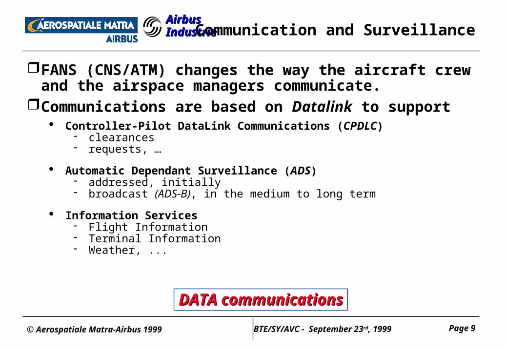
FANS (CNS/ATM) changes the way the aircraft crew and the airspace managers communicate.
Communications are based on Datalink to support Controller-Pilot DataLink Communications (CPDLC)
clearances requests, …
Automatic Dependant Surveillance (ADS) addressed, initially broadcast (ADS-B), in the medium to long term
Information Services Flight Information Terminal Information Weather, ...
DATA communicationsDATA communications
© Aerospatiale Matra-Airbus 1999 Page 10BTE/SY/AVC - September 23rd, 1999
Airbus IndustrieAirbus Industrie
CNS/ATM environments
© Aerospatiale Matra-Airbus 1999 Page 11BTE/SY/AVC - September 23rd, 1999
Airbus IndustrieAirbus Industrie Environment - general
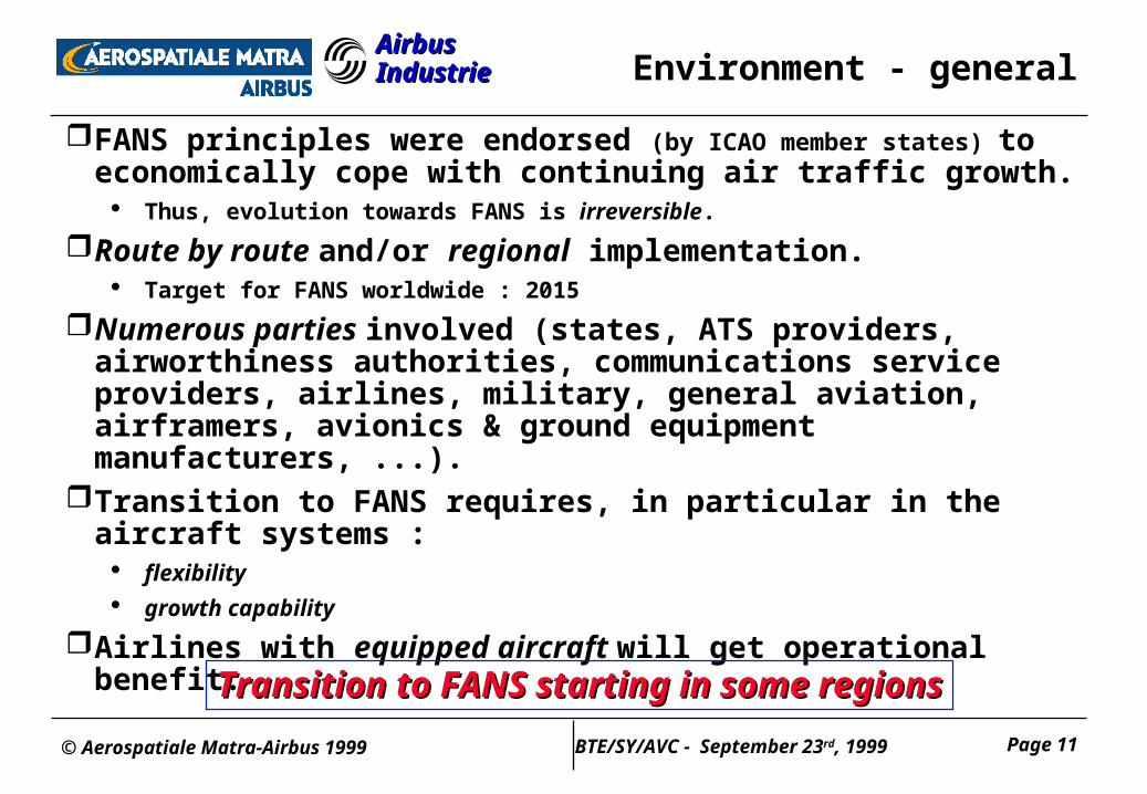
FANS principles were endorsed (by ICAO member states) to economically cope with continuing air traffic growth.
Thus, evolution towards FANS is irreversible.
Route by route and/or regional implementation. Target for FANS worldwide : 2015
Numerous parties involved (states, ATS providers, airworthiness authorities, communications service providers, airlines, military, general aviation, airframers, avionics & ground equipment manufacturers, ...).
Transition to FANS requires, in particular in the aircraft systems : flexibility growth capability
Airlines with equipped aircraft will get operational benefit.
Transition to FANS starting in some regionsTransition to FANS starting in some regions
© Aerospatiale Matra-Airbus 1999 Page 12BTE/SY/AVC - September 23rd, 1999
Airbus IndustrieAirbus Industrie Main steps of evolution
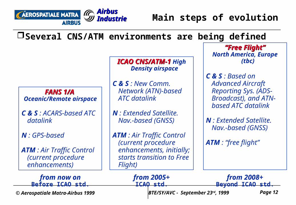
Several CNS/ATM environments are being defined
ICAO CNS/ATM-1 ICAO CNS/ATM-1 High Density airspace
C & S : New Comm. Network (ATN)-based ATC datalink
N : Extended Satellite. Nav.-based (GNSS)
ATM : Air Traffic Control (current procedure enhancements, initially; starts transition to Free Flight)
from 2005+ICAO std.
FANS 1/A FANS 1/A Oceanic/Remote airspace
C & S : ACARS-based ATC datalink
N : GPS-based
ATM : Air Traffic Control (current procedure enhancements)
from now onBefore ICAO std.
““Free Flight”Free Flight”North America, Europe
(tbc)
C & S : Based on Advanced Aircraft Reporting Sys. (ADS-Broadcast), and ATN-based ATC datalink
N : Extended Satellite. Nav.-based (GNSS)
ATM : “free flight”
from 2008+Beyond ICAO std.

© Aerospatiale Matra-Airbus 1999 Page 13BTE/SY/AVC - September 23rd, 1999
Airbus IndustrieAirbus Industrie
Airbus design
© Aerospatiale Matra-Airbus 1999 Page 14BTE/SY/AVC - September 23rd, 1999
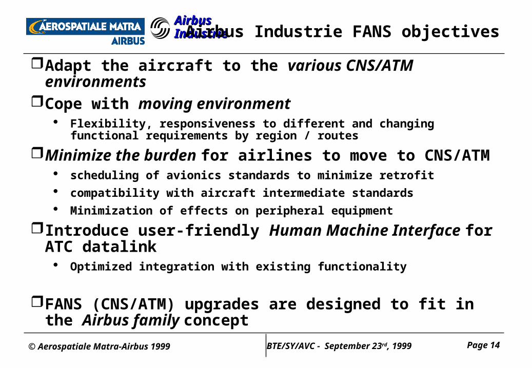
Airbus IndustrieAirbus Industrie Airbus Industrie FANS objectives
Adapt the aircraft to the various CNS/ATM environmentsCope with moving environment
Flexibility, responsiveness to different and changing functional requirements by region / routes
Minimize the burden for airlines to move to CNS/ATM scheduling of avionics standards to minimize retrofit
compatibility with aircraft intermediate standards
Minimization of effects on peripheral equipment
Introduce user-friendly Human Machine Interface for ATC datalink
Optimized integration with existing functionality
FANS (CNS/ATM) upgrades are designed to fit in the Airbus family concept
© Aerospatiale Matra-Airbus 1999 Page 15BTE/SY/AVC - September 23rd, 1999
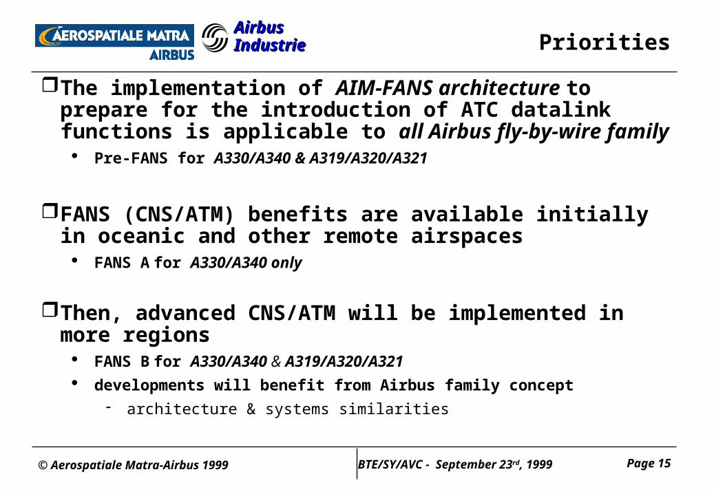
Airbus IndustrieAirbus Industrie Priorities
The implementation of AIM-FANS architecture to prepare for the introduction of ATC datalink functions is applicable to all Airbus fly-by-wire family
Pre-FANS for A330/A340 & A319/A320/A321
FANS (CNS/ATM) benefits are available initially in oceanic and other remote airspaces
FANS A for A330/A340 only
Then, advanced CNS/ATM will be implemented in more regions FANS B for A330/A340 & A319/A320/A321
developments will benefit from Airbus family concept
architecture & systems similarities
© Aerospatiale Matra-Airbus 1999 Page 16BTE/SY/AVC - September 23rd, 1999
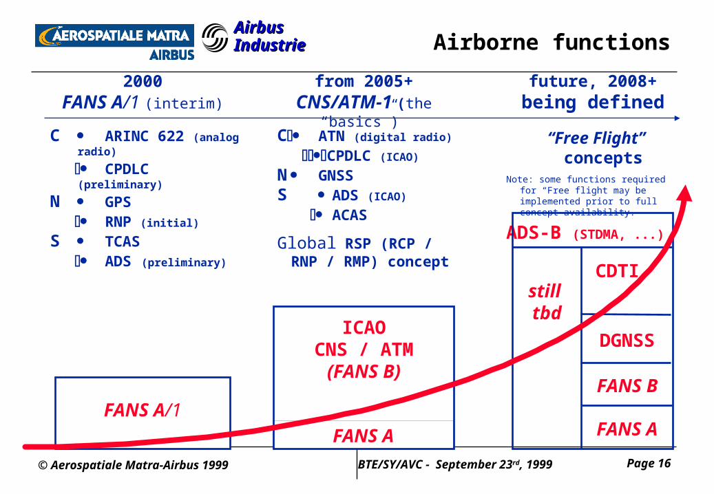
Airbus IndustrieAirbus Industrie Airborne functions
C ARINC 622 (analog radio)
CPDLC (preliminary)
N GPS RNP (initial)
S TCAS ADS (preliminary)
2000FANS A/1 (interim)
FANS A/1
C ATN (digital radio)
CPDLC (ICAO)
N GNSSS ADS (ICAO)
ACAS
GlobalRSP (RCP / RNP / RMP) concept
from 2005+CNS/ATM-1 (the “basics”)
ICAOCNS / ATM(FANS B)
FANS A
future, 2008+being defined
“Free Flight” concepts
Note: some functions required for “Free flight may be implemented prior to full concept availability.
ADS-B (STDMA, ...)
still tbd
DGNSS
FANS A
CDTI
FANS B
© Aerospatiale Matra-Airbus 1999 Page 17BTE/SY/AVC - September 23rd, 1999
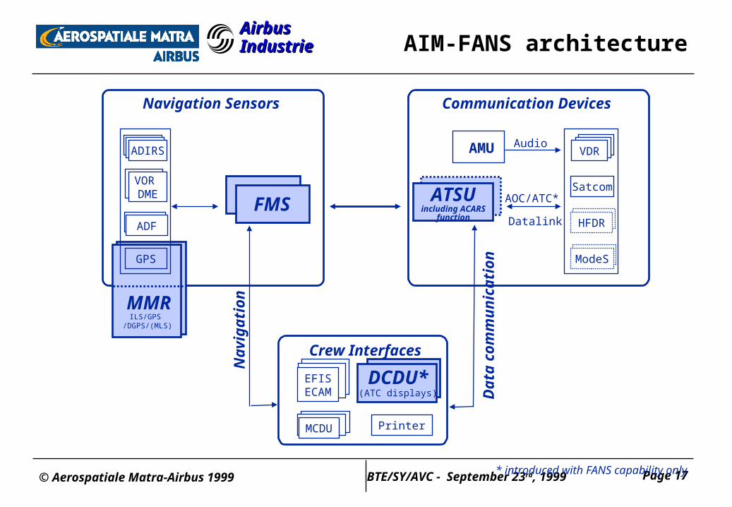
Airbus IndustrieAirbus Industrie
Crew Interfaces
Printer
EFISECAM
MCDU
Dat
a co
mm
un
icat
ion
Nav
igat
ion
AIM-FANS architecture
* introduced with FANS capability only
DCDU*(ATC displays)
VDR
Satcom
HFDR
ModeS
Communication Devices
AMU
AOC/ATC*
Datalink
Audio
ATSUincluding ACARS
function
ADIRS
ADF
FMS
Navigation Sensors
GPS
MMR
ILS/GPS /DGPS/(MLS)
VOR DME
© Aerospatiale Matra-Airbus 1999 Page 18BTE/SY/AVC - September 23rd, 1999
Airbus IndustrieAirbus Industrie AIM-FANS steps
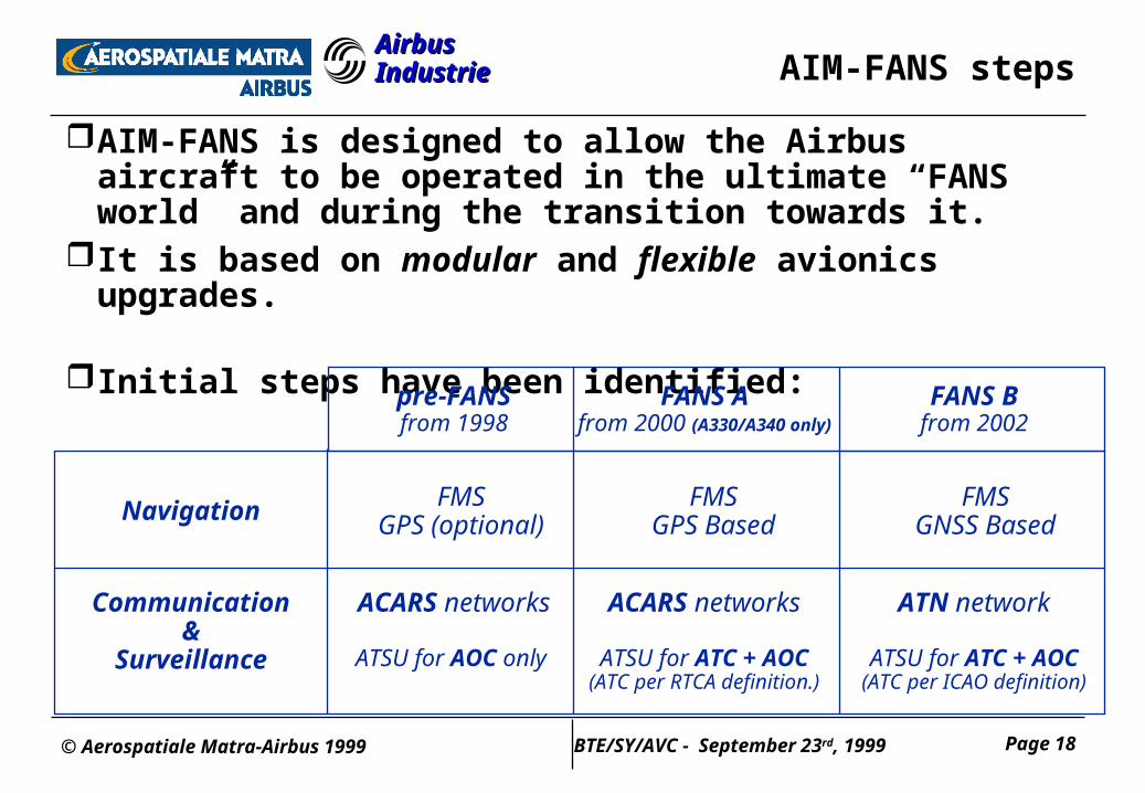
AIM-FANS is designed to allow the Airbus aircraft to be operated in the ultimate “FANS world” and during the transition towards it.
It is based on modular and flexible avionics upgrades.
Initial steps have been identified:
FANS Afrom 2000 (A330/A340 only)
FANS Bfrom 2002
FMSGPS Based
ACARS networks
ATSU for ATC + AOC(ATC per RTCA definition.)
FMSGNSS BasedNavigation
Communication&
Surveillance
ATN network
ATSU for ATC + AOC(ATC per ICAO definition)
pre-FANSfrom 1998
FMSGPS (optional)
ACARS networks
ATSU for AOC only
© Aerospatiale Matra-Airbus 1999 Page 19BTE/SY/AVC - September 23rd, 1999
Airbus IndustrieAirbus Industrie
Data Communications
© Aerospatiale Matra-Airbus 1999 Page 20BTE/SY/AVC - September 23rd, 1999
Airbus IndustrieAirbus Industrie Data Communications
Future aircraft data communication functions will include :
Airline data communication functions (ACARS function or AOC - Airline Operational Communication), including FMS-ACARS interface (e.g. Flight Plan uplink, progress reports, maintenance reports, … for airline use)
ATC data communications functions, introducing extensive data communication between aircraft (flight crew, systems) and Air Traffic Control Managers
© Aerospatiale Matra-Airbus 1999 Page 21BTE/SY/AVC - September 23rd, 1999
Airbus IndustrieAirbus Industrie ATSU definition
The ATSU (Air Traffic Services Unit) is introduced to support emerging ATC datalink functions
is developed and manufactured by Aerospatiale
hosts functions that were previously in ACARS MU/CMU :
ACARS router (subcontracted to Rockwell-Collins) to select communication media
to manage interface with aircraft ACARS user systems (FMS, CMS / CFDS, ACMS / AIDS)
Note : these interfaces are available even if AOC software is not installed
specific airline applications (AOC software) which are BFE in the ATSU (choice between Allied Signal and Rockwell-Collins)
to perform specific airline functions, such as OOOI, delay, load sheet, fuel on board, gate assignment, ... reports
© Aerospatiale Matra-Airbus 1999 Page 22BTE/SY/AVC - September 23rd, 1999
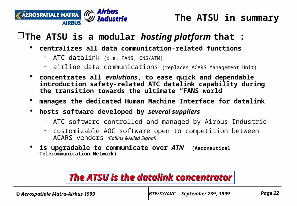
Airbus IndustrieAirbus Industrie The ATSU in summary
The ATSU is a modular hosting platform that : centralizes all data communication-related functions
ATC datalink (i.e. FANS, CNS/ATM)
airline data communications (replaces ACARS Management Unit)
concentrates all evolutions, to ease quick and dependable introduction safety-related ATC datalink capability during the transition towards the ultimate “FANS world”
manages the dedicated Human Machine Interface for datalink
hosts software developed by several suppliers ATC software controlled and managed by Airbus Industrie customizable AOC software open to competition between ACARS vendors (Collins
&Allied Signal)
is upgradable to communicate over ATN (Aeronautical Telecommunication Network)
The ATSU is the datalink concentratorThe ATSU is the datalink concentrator
© Aerospatiale Matra-Airbus 1999 Page 23BTE/SY/AVC - September 23rd, 1999
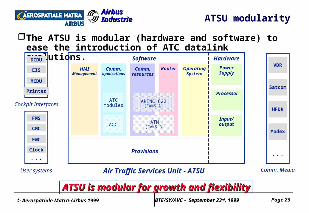
Airbus IndustrieAirbus Industrie ATSU modularity
The ATSU is modular (hardware and software) to ease the introduction of ATC datalink evolutions.
RouterHMIManagement
Comm.resources
ARINC 622(FANS A)
ATN(FANS B)
ATSU is modular for growth and flexibilityATSU is modular for growth and flexibility
Comm. Media
VDR
Satcom
HFDR
ModeS
...
Air Traffic Services Unit - ATSU
PowerSupply
Comm.applications
ATCmodules
AOC
OperatingSystem
Provisions
Processor
Input/output
Software Hardware
Cockpit Interfaces
DCDU
EIS
MCDU
Printer
User systems
...
FMS
CMC
FWC
Clock
© Aerospatiale Matra-Airbus 1999 Page 24BTE/SY/AVC - September 23rd, 1999
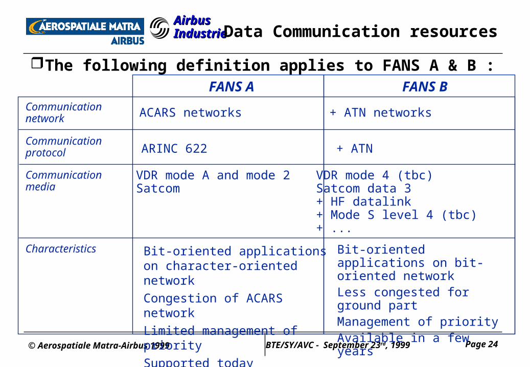
Airbus IndustrieAirbus Industrie Data Communication resources
The following definition applies to FANS A & B :
Communicationnetwork
Communicationprotocol
Communicationmedia
Characteristics
ACARS networks + ATN networks
ARINC 622 + ATN
VDR mode A and mode 2Satcom
VDR mode 4 (tbc)Satcom data 3+ HF datalink+ Mode S level 4 (tbc)+ ...
Bit-oriented applications on character-oriented network
Congestion of ACARS network
Limited management of priority
Supported today
Bit-oriented applications on bit-oriented networkLess congested for ground partManagement of priorityAvailable in a few years
FANS A FANS B
© Aerospatiale Matra-Airbus 1999 Page 25BTE/SY/AVC - September 23rd, 1999
Airbus IndustrieAirbus Industrie
Human Machine Interface for ATC datalink
© Aerospatiale Matra-Airbus 1999 Page 26BTE/SY/AVC - September 23rd, 1999
Airbus IndustrieAirbus Industrie HMI - principles
A new situation audio progressively complemented by written messages
ATC ultimately replaced by ATM
Deep changes Human to human relationship
Human to machine relationship
Constraints Maintain coherence with existing cockpit design
take into account flight crew experience with existing aircraft types
Methodology Systematic human factors evaluation
© Aerospatiale Matra-Airbus 1999 Page 27BTE/SY/AVC - September 23rd, 1999
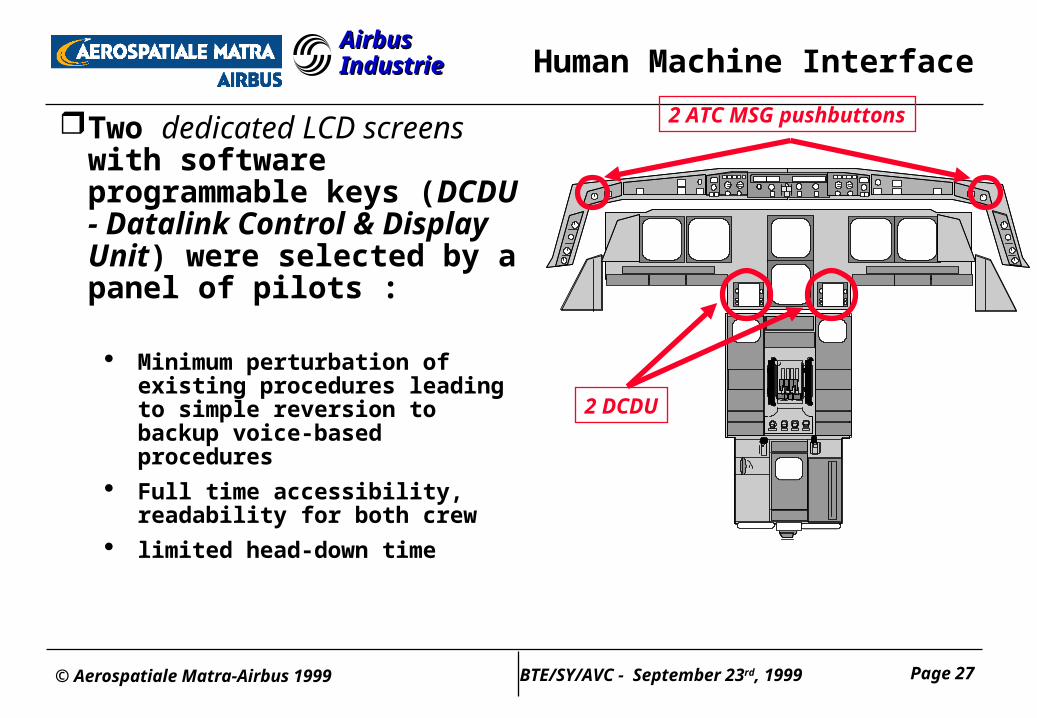
Airbus IndustrieAirbus Industrie Human Machine Interface
Two dedicated LCD screens with software programmable keys (DCDU - Datalink Control & Display Unit) were selected by a panel of pilots :
Minimum perturbation of existing procedures leading to simple reversion to backup voice-based procedures
Full time accessibility, readability for both crew
limited head-down time
2 ATC MSG pushbuttons
2 DCDU
© Aerospatiale Matra-Airbus 1999 Page 28BTE/SY/AVC - September 23rd, 1999
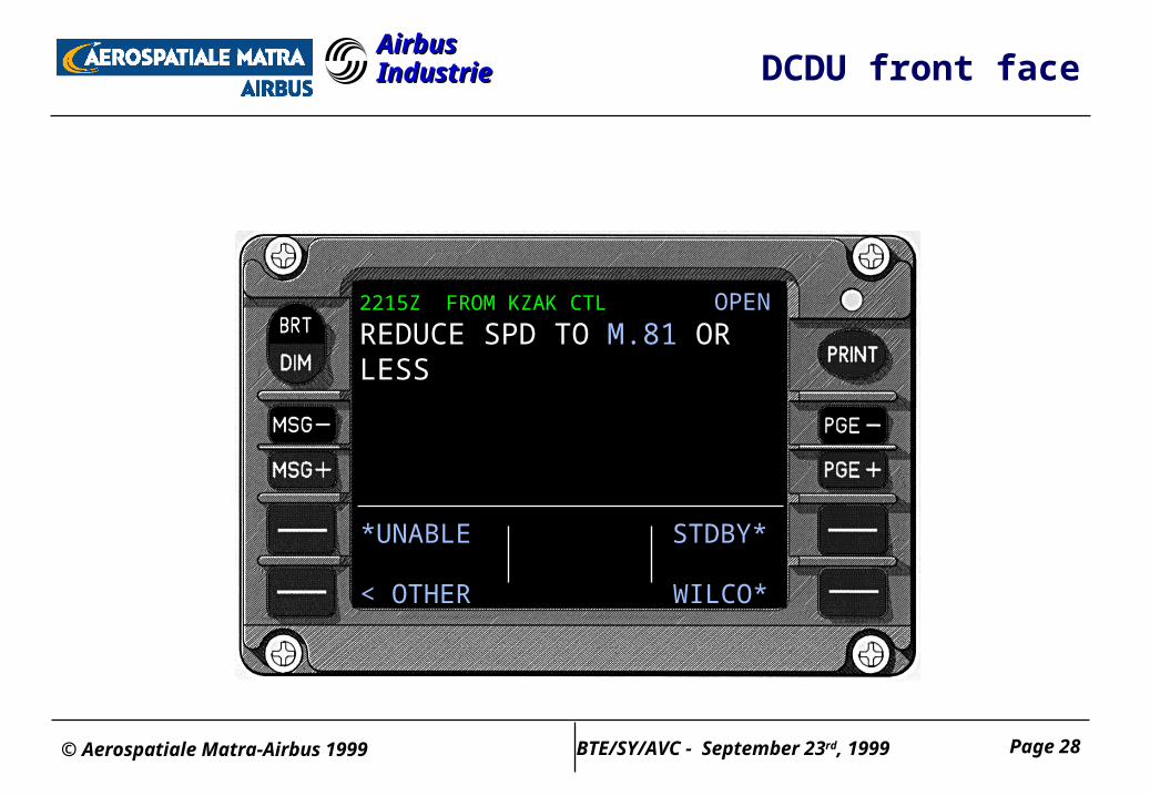
Airbus IndustrieAirbus Industrie DCDU front face
2215Z FROM KZAK CTL OPEN
REDUCE SPD TO M.81 ORLESS
*UNABLE
< OTHER WILCO*
STDBY*
© Aerospatiale Matra-Airbus 1999 Page 29BTE/SY/AVC - September 23rd, 1999
Airbus IndustrieAirbus Industrie
The “alert” function - general
When a message is uplinked to the aircraft by the Air Traffic Manager, the crew is alerted through :
Visual attention getter
flashing blue “ATC MSG” pushbuttons on the glareshield
Note : uplink message arrival is also visualized on the two DCDUs
Audio attention getter
dedicated sound (American telephone)
Note : for all but urgent messages, there is a time delay (after visual attention getter) before audio alert is triggered
© Aerospatiale Matra-Airbus 1999 Page 30BTE/SY/AVC - September 23rd, 1999
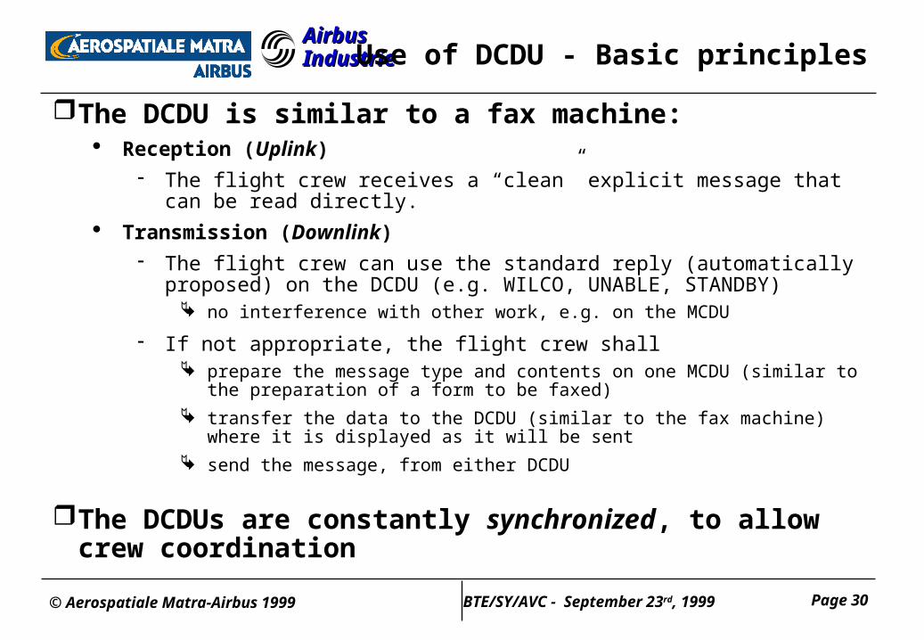
Airbus IndustrieAirbus Industrie Use of DCDU - Basic principles
The DCDU is similar to a fax machine: Reception (Uplink)
The flight crew receives a “clean” explicit message that can be read directly.
Transmission (Downlink)
The flight crew can use the standard reply (automatically proposed) on the DCDU (e.g. WILCO, UNABLE, STANDBY)
no interference with other work, e.g. on the MCDU
If not appropriate, the flight crew shall prepare the message type and contents on one MCDU (similar to the preparation of a form
to be faxed)
transfer the data to the DCDU (similar to the fax machine) where it is displayed as it will be sent
send the message, from either DCDU
The DCDUs are constantly synchronized, to allow crew coordination
© Aerospatiale Matra-Airbus 1999 Page 31BTE/SY/AVC - September 23rd, 1999
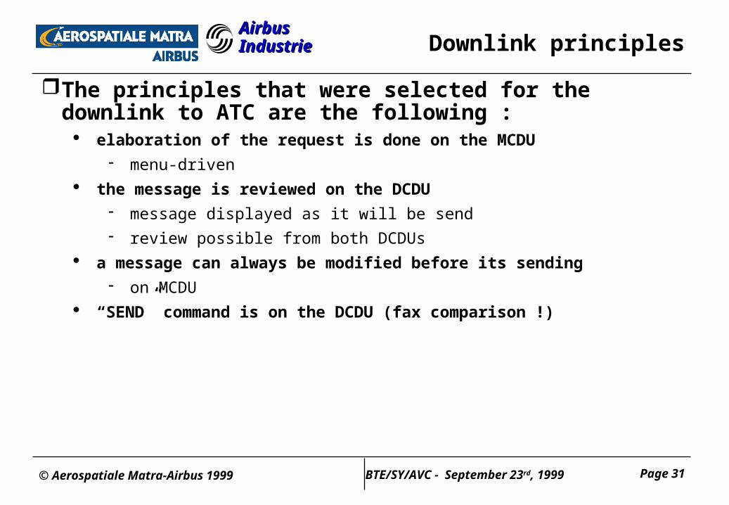
Airbus IndustrieAirbus Industrie Downlink principles
The principles that were selected for the downlink to ATC are the following :
elaboration of the request is done on the MCDU
menu-driven
the message is reviewed on the DCDU
message displayed as it will be send
review possible from both DCDUs
a message can always be modified before its sending
on MCDU
“SEND” command is on the DCDU (fax comparison !)
© Aerospatiale Matra-Airbus 1999 Page 32BTE/SY/AVC - September 23rd, 1999
Airbus IndustrieAirbus Industrie
Experience Gained
© Aerospatiale Matra-Airbus 1999 Page 33BTE/SY/AVC - September 23rd, 1999
Airbus IndustrieAirbus Industrie Experience Gained
AIM FANS Implementation Pre FANS on A340 & A320
Projects: Petal I
EOLIA / Pro ATN
© Aerospatiale Matra-Airbus 1999 Page 34BTE/SY/AVC - September 23rd, 1999
Airbus IndustrieAirbus IndustrieEOLIA/ProATN Le Bourget ‘99 (1)
A highly successful demonstration, involvingAirsys ATM ATC ground station
Aerospatiale MATRA-Airbus A340 simulator
NLR Cessna Citation II research aircraft
EOLIA kernel servicesADS position reporting
14 CPDLC messages from the CIC set
(8 uplink/5downlink)
Basic DLIC/ACM functionality
© Aerospatiale Matra-Airbus 1999 Page 35BTE/SY/AVC - September 23rd, 1999
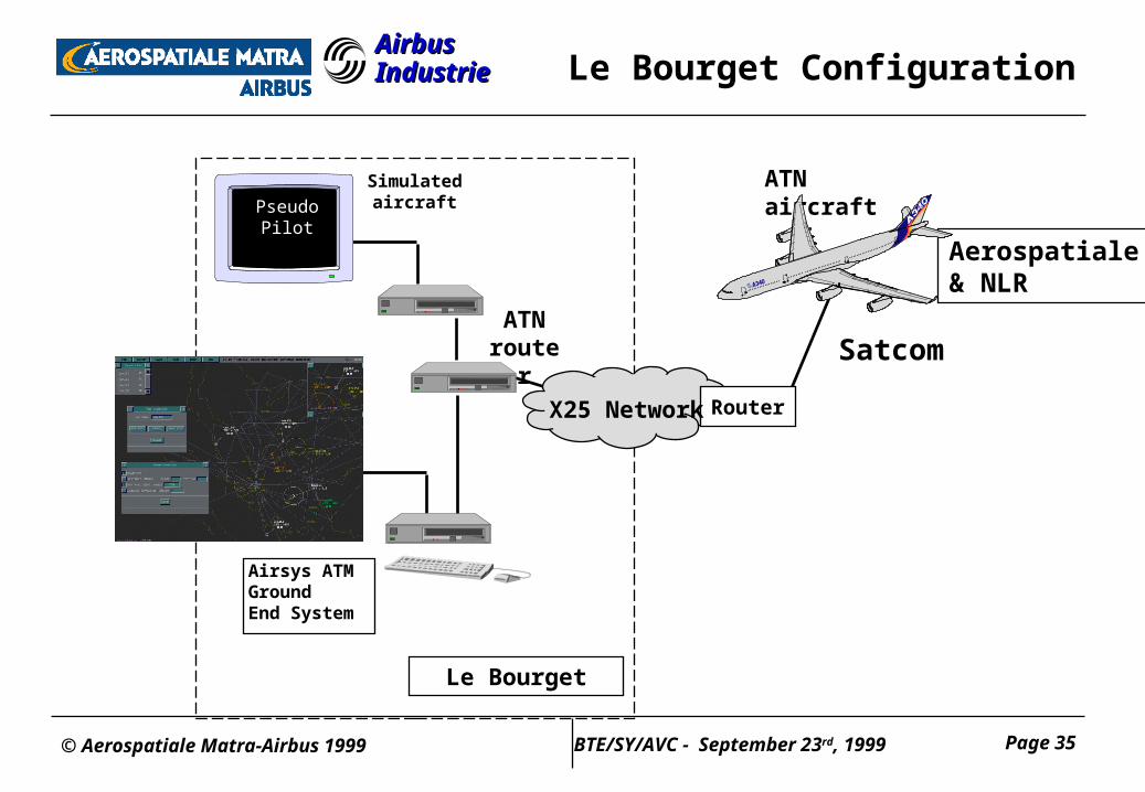
Airbus IndustrieAirbus Industrie Le Bourget Configuration
Le Bourget
ATNrouter
Airsys ATMGroundEnd System
ATN aircraft
X25 Network
Satcom
Simulatedaircraft
RouterX25 Network
PseudoPilot
Aerospatiale& NLR
© Aerospatiale Matra-Airbus 1999 Page 36BTE/SY/AVC - September 23rd, 1999
Airbus IndustrieAirbus Industrie EOLIA/ProATN Le Bourget ‘99 (2)
ProATN infrastructure using SATCOM data-3 subnetwork
Daily demonstrationsLocal simulations
Single aircraft demonstrations
A340 simulator with video link from cockpit
Cessna Citation aircraft with 2 observers (6 flights)
Multi aircraft demonstrations
A340 simulator and Cessna Citation II
© Aerospatiale Matra-Airbus 1999 Page 37BTE/SY/AVC - September 23rd, 1999
Airbus IndustrieAirbus Industrie Le Bourget ‘99 feedback
Demonstrations showed ATN at work in a near-operational environment on industrial airborne platform (ATSU)
Positive feedback from observers on LACK implementation
CPDLC roundtrip delay approx. 3 sec (High gain antenna), 10 sec (Low gain antenna)
Paved the way for full EOLIA/ProATN evaluations in 1999/2000
© Aerospatiale Matra-Airbus 1999 Page 38BTE/SY/AVC - September 23rd, 1999
Airbus IndustrieAirbus Industrie Plans for the near future
Full EOLIA servicesFull ACM implementation
Expanded CPDLC message set
FLIPCY
Additional ground sites (incl. Multi-site)
Cohabitation Satcom & VDL-2 (ProATN)
Evaluation trials with full servicesFlight trials
Simulations
© Aerospatiale Matra-Airbus 1999 Page 39BTE/SY/AVC - September 23rd, 1999
Airbus IndustrieAirbus Industrie
Conclusion
© Aerospatiale Matra-Airbus 1999 Page 40BTE/SY/AVC - September 23rd, 1999
Airbus IndustrieAirbus Industrie Conclusion : Airbus AIM FANS
FANS (CNS/ATM) is implemented to support air traffic growthSignificant operational benefits may be available for equipped
aircraftAirbus offers AIM-FANS, a flexible approach to CNS/ATM
implementation to cover gradual, benefits-driven implementation of ATM environment
worldwide
to allow airlines to transition at their preferred pace towards “FANS” world
start with existing airline datalink capability
designed to support upgrades for ATC datalink
AIM-FANS design has been validated with airlines
It is based on common hardware (ATSU, DCDU, FMS) for all Airbus fly-by-wire fleets (A319/A320/A321, A330/A340), as well as some common software.
It has growth potential to support evolving standards
with projects
© Aerospatiale Matra-Airbus 1999 Page 41BTE/SY/AVC - September 23rd, 1999
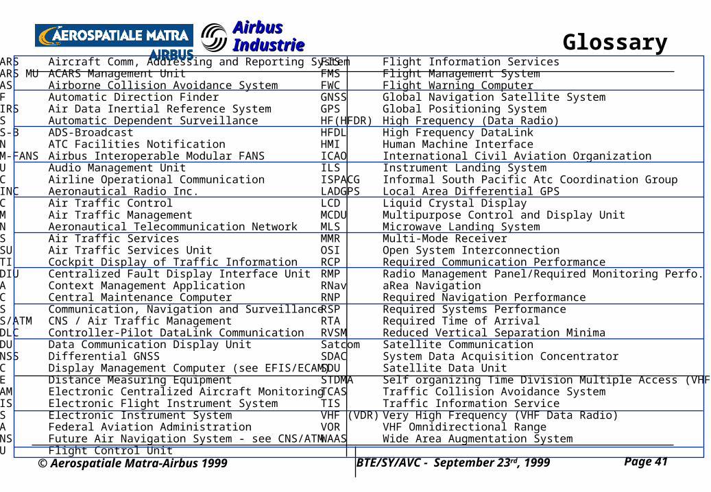
Airbus IndustrieAirbus Industrie GlossaryACARS Aircraft Comm, Addressing and Reporting SystemACARS MU ACARS Management UnitACAS Airborne Collision Avoidance SystemADF Automatic Direction FinderADIRS Air Data Inertial Reference SystemADS Automatic Dependent SurveillanceADS-B ADS-BroadcastAFN ATC Facilities NotificationAIM-FANS Airbus Interoperable Modular FANSAMU Audio Management UnitAOC Airline Operational Communication ARINC Aeronautical Radio Inc. ATC Air Traffic ControlATM Air Traffic Management ATN Aeronautical Telecommunication Network ATS Air Traffic Services ATSU Air Traffic Services UnitCDTI Cockpit Display of Traffic InformationCFDIU Centralized Fault Display Interface UnitCMA Context Management ApplicationCMC Central Maintenance ComputerCNS Communication, Navigation and SurveillanceCNS/ATM CNS / Air Traffic ManagementCPDLC Controller-Pilot DataLink CommunicationDCDU Data Communication Display UnitDGNSS Differential GNSSDMC Display Management Computer (see EFIS/ECAM)DME Distance Measuring EquipmentECAM Electronic Centralized Aircraft MonitoringEFIS Electronic Flight Instrument SystemEIS Electronic Instrument SystemFAA Federal Aviation AdministrationFANS Future Air Navigation System - see CNS/ATMFCU Flight Control Unit
FIS Flight Information ServicesFMS Flight Management SystemFWC Flight Warning ComputerGNSS Global Navigation Satellite System GPS Global Positioning System HF(HFDR) High Frequency (Data Radio)HFDL High Frequency DataLinkHMI Human Machine InterfaceICAO International Civil Aviation OrganizationILS Instrument Landing SystemISPACG Informal South Pacific Atc Coordination GroupLADGPS Local Area Differential GPSLCD Liquid Crystal DisplayMCDU Multipurpose Control and Display UnitMLS Microwave Landing SystemMMR Multi-Mode ReceiverOSI Open System InterconnectionRCP Required Communication PerformanceRMP Radio Management Panel/Required Monitoring Perfo.RNav aRea NavigationRNP Required Navigation PerformanceRSP Required Systems PerformanceRTA Required Time of ArrivalRVSM Reduced Vertical Separation MinimaSatcom Satellite CommunicationSDAC System Data Acquisition ConcentratorSDU Satellite Data UnitSTDMA Self organizing Time Division Multiple Access (VHF)TCAS Traffic Collision Avoidance SystemTIS Traffic Information ServiceVHF (VDR) Very High Frequency (VHF Data Radio)VOR VHF Omnidirectional RangeWAAS Wide Area Augmentation System