,>/ ,9 dp frz>i. /r ftfcwi 7 - defense technical information … 9 dp nos'iti frz>i....
TRANSCRIPT
,>/ ,9 DP noS'iti frz>i. /r ftfcwi HI 7
HEADQUARTERS QUARTERMASTER RESEARCH AND ENGINEERING COMMAND* US ARMY Quartermaster Research and Engineering Center
Natick, fefbssachusetts
O
CHEMICALS AND PLASTICS DIVISION Plastics Section Report No. 4
EVALUATION OF ENERGY DISSIPATING MATERIALS FOR USE IN AERIAL DELIVERY OF C-RATIONS
By Helen Wong
Protective Materiel Branch
Project Reference? 7-Ö7-03-004
D. AC^DEPARTMENT 0F DEFENSE ^ ELASTICS TECHNICAL tVALUATION CENTER
PICATiNNY ARSENAL, DOVER, N J
«SSfiffiSJ
July 1959
r* UNCLASSIFIED /UNLIMTTED ■ DTK QUALITY INSPECTED 1

DISCLÄIMKI NOTICE
THIS DOCUMENT IS BEST
QUALITY AVAILABLE. THE COPY
FURNISHED TO DTIC CONTAINED
A SIGNIFICANT NUMBER OF
PAGES WHICH DO NOT
REPRODUCE LEGIBLY.

Mr HEADQUARTERS QUARTERMASTER RESEARCH AND ENGINEERING COMMAND, US- ARMY Quartermaster Research and Engineering Center, x
Natick,/Massachusetts. (F*. -. .,./%'
CHEMICALS AND PLASTICS DIVISION \ Plastics Section Report No« 4
V' )
h
\
p EVALUATION OF ENERGY DISSIPATING MATERIALS FOR USE \ IN AERIAL DELIVERY OF C-RATIONS \
im CuM* By
——~y Helen Wong. -Proteetive Materiel; JBranch
/
Project References / 7-87-03-004 /
_-/-
JU17 1959
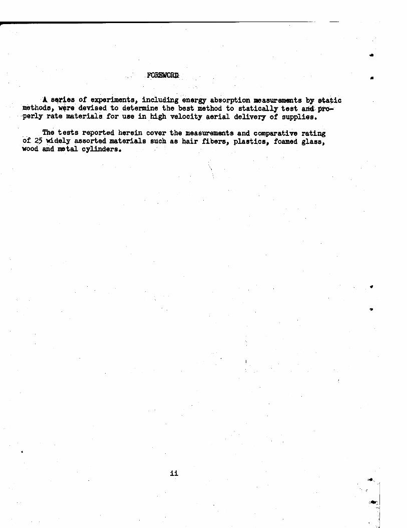
FOBEWQRE
A series of experiments, including energy absorption measurements by static methods, were devised to determine the best method to statically test and pro- perly rate materials for use in high velocity aerial delivery of supplies.
The tests reported herein cover the measurements and comparative rating of 25 widely assorted materials such as hair fibers, plastics, foamed glass, wood and metal cylinders»
ii

TABLE OF CONTENTS
S SUMMARY .. vi
INTRODUCTION 1
MATERIALS 2
PART I FIBERS
Introduction 2
Section A Hairs Felt Pads ,2
PART II PLASTICS
Introduction 2
Section A Polyurethane Foams
Flexible polyurethane foams 3
Polyester urethane
Vibrafoam 41255
Semi-rigid polyurethane foams 3
Semi-rigid Collofoam
Rigid polyurethane foams J>
Rigid Collofoam
Section B - Viavl Foams
Flexible vinyl foam 5
Vinyl foam 505
Semi-rigid vinyl foam 7
Flutterstock
iii
Page Section C Polyethylene Foam
Flexible polyethylene foam
Experimental plastic Q4139.2 7
Section D Polystyrene Foanls
Commercial polystyrene foams 9
Styrofoam 22
Self-extinguishing polystyrene foam 9
Styrofoam 33
Experimental polystyrene foams 13
Experimental plastic $L03.15
Experimental plastic Q103.21
Expendable-in-place polystyrene foam 13
Experimental plastic @865»2
Section E Acrylate Foam
Rigid acrylate foam 17
Foamed Plexiglas
Section F Epoxy Foam
Rigid epoxy resin foam 17
Eccofoam FP
Section G Resin Impregnated Fiberglas
Resin impregnated glass fiber 17
Fiberglas honeycomb
PARE III INORGANIC MATERIALS 19
Section A Silicaceous Materials
Fibrous fireproof silicate blocks 19
Asbestos blocks
iv

Page
Hydrous calcium silicate blocks 2k
Kaylo block insulation
Kaylo»20 block insulation
Silica
Commercial Foamglas 2k
Experimental Foamglas 2k
Section B Metals
Foamed aluminum 29
Empty metal cans 29
PART IV WOOD AND WOOD PRODUCTS
Introduction 33
Section A Wood
Balsa wood blocks 33
EXPERIMENTAL TEST METHODS 3$
COMPARISON AND DISCUSSION 38
CONCLUSIONS kl
RECOMMENDATIONS kl
ACKNOWLEDGEMENTS kl.

SUMMARY
A value of 100 - 200 lbs/square inch stress under static low speed com- pression test is established as the minimum for screening materials for potential application as energy dissipators in aerial delivery of C-rations.
Twenty-five materials were tested statically in compression at various low speeds on an Instron tester« Of these, thirteen including hair felt, flexible polyester urethane and vinyl foams were found to be unsatisfactory due to low energy dissipation values comfcaned" with high resilience. Some experimental flexible po^ethylene foams» polystyrene beads and semi-rigid vinyl foams gave acceptable stress values but their resilience"is too high. Rigid balsa blocks are unsatisfactory due to low energy dissipation. The stress values for rigid acrylate foams,, hydrous calcium silicate, rigid epoxy jresin and foamed aluminum are"lugner than the required minimum but the densities of these materials are too high for application in aerial delivery.
Eight materials, such as rigWj^ly^rethane and polystyrene foams, resin impregnated glass fibers, fibrous silicate"blbcfcs (asbestos) experimental and commercial Ijbamglas, metal cans and polystyrene beads are found to be potentially suitable for application as aerial delivery energy dissipators.
Low density; cellular and foamed materials have superior energy dissipation characteristics to more dense materials.
vi

EVALUATION OF ENERGY" DISSIPATING MATERIALS FOR USE IN AERIAL DELIVERY OF C-RATIONS
INTRODUCTION"
Increased mobility inherent in modern warfare demands a quick and accurate means of supply to provide the combat soldier with food, clothing and equipment. Since the fastest delivery is by air, a method is required so that the dropped items land intact at the desired locationo Current methods of aerial supply employ large parachutes as descent retarding devices. However, due to the size of these retarders, the accuracy of aerial drops is diminished due to wind drift. Consequently, if dropped items are remote, even though intact, they are of no use to the potential receivers» While a drop is more accurate with the elimination of the retarder, without cushioning some items would be rendered useless from damage upon impact with the ground.
A more practical system would be to use a small retarder along with a cushioning material to absorb the load energy upon impact. It is re- quired that the cushioning material dissipate all the kinetic energy of the system at a stress value below the breaking strength (hereinafter ©ailed the fragility limit) of the dropped item. Other important charac- teristics of the cushioning material are its ability to deform uniformly upon compression throughout at least 75 percent of its volume and minimum resilience in order to utilize its energy dissipation properties to the maximum with a minimum bounce or return of the load platform upon impact with the ground.
Since actual aerial drop tests are expensive and time consuming, static laboratory tests were made on a number of different materials to determine their behavior under compression. The criteria of low resilience and high unit energy dissipation value under a 100=200 pounds/square inch stress were employed in the tests to evaluate potential energy dissipators.
Hair fibers, plastics, inorganic materials, wood and metal cans were investigated for potential application as energy dissipators in the aerial delivery of Gyrations. A description and discussion is given of each candidate material tested.
MATERIALS
PART I FIBERS
Introduction
Various types of fibrous materials are used commercially in the packing and packaging of items for shipment and in seat cushions. These materials have been found to be adequate in the absorption of the low velocity shock encountered under usual shipping conditions. Since air dropped items also require a shock absorber, representative fibrous materials were evaluated as possible aerial delivery energy dissipators.
Section k Hairs
Felt Pads
Static compression tests were conducted on samples of felt shock pads which have been used as an aerial delivery cushioning material. Although actual field tests had proved that felt pads were inadequate as an energy dissipator, laboratory tests were made to establish some basis on which to screen other materials for application as energy dissipators. Twelve samples were compressed to the bottoming point at 50 percent deformation indicating that only one-half of the cushion thickness can be utilized effectively. A considerable variation was found in the data which may be due to the difference in density of the material or to the speed of testing. Since a high resi- lience of 35 percent was obtained along with very low energy dissipation values (Figure l), static laboratory compression tests confirm the fact that felt pads are inadequate as a cushioning material for high velocity aerial drops»
PART II PLASTICS
Introduction
Rigid plastic foams are used commercially as shock absorbers in packaging fragile items so that the concept of their use as aerial delivery energy dissipators is not entirely new. Although these foams are satisfactory as a package cushion, their behavior under dynamic or high velocity impact test remains to be determined. A favorable characteristic of many of these plastic foams is the ease of manufacture at a relatively low coet. In addition, since many different types of items are air dropped,, different densities of

the same foam can be made to accommodate various items. This variation in density is accomplished simply by varying the proportion of the ingredients that are used in making the foam*. The utilization of one formula of plastic foam of different densities as energy dissipators for all dropped items instead of a different type of energy dissipator for each item offers many advantages., Hence, a variety of plastic foams and many different densities of the same foam were tested statically.
Section A Polyurethane Foams
Flexible Pols
Polyester Urethane and Vibrafoam 41255
Since flexible polyurethane foams are among those commercial materials currently used in cushions and in automobile crash pads, static laboratory tests were conducted on two types of commercial polyurethane foams to in- vestigate their properties as potential energy dissipators for high velocity aerial drop systems. Twelve samples of polyester urethane and nine samples of Vibrafoam 41255 were compressed to 25 percent deformation. The densities of the foam were found to be quite lows 2.7 lbs./cu.ft« for the polyester urethane and 3o9 Ibs./cu.ft. for Vibrafoam 41255« As shown in Figures 2 and 3s both foams deformed similarly under compression. The data obtained shows that these flexible polyurethane foams are much too resilient to be used as energy dissipators for high velocity aerial drops. Although the loading compression curve is similar to that for an ideal cushioning material, the deforming stress is too low to effectively cushion heavy loads for drops because the initial weight of the items to be cushioned would be enough to deform the foam considerably.
Semi-Rigid Polyurethane Foams
Semi~Rlgid Gollofoam
Previous tests had shown that although flexible polyurethane foams deform at a relatively constant stress, they are entirely too soft and resilient for use as energy dissipators. As a result, a more rigid polyurethane foam was
«Murray, G.E. and Levin, M. - Interim Beport on the Development of Foamed Plastics as Energy Dissipators, Chemicals & Plastics Division, QM R&E Center, Natick, Mass. 1 July 1957<>

1*1
0/ 0* ft* OTJMAV m INCHES//NCN
a« »3 ö <nw OJO a/s ato ats ato STRAIN IM IMCHES//NCH
FIG. I FEL T SHOCK PADS TESTSPEEO 20 INCHES/MINUTE
SIZE *V*V
/7£<? POLYESTER UPETHANE TEST SPEED Ü2 /NCHES/MINUTE
SIZE l.t'xl'
aas am am ax» aas aso STRAW IN IHCHB/WCH a.4 as
STRAIN JN INCHES/INCH
F/G.3 V/BPAFO/IM 4/2.55 TEST SPEED O.Z INCHES /M/NUTE
SIZE/./'"/'
FIG. 4 SEMI-RIGID C0LWF0AM TESTSPEEO 2 INCHES/MINUTE
S/ZEfx**2'
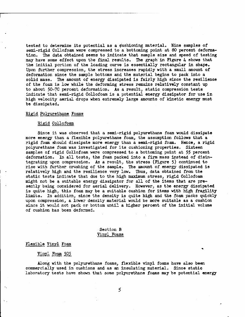
tested to determine its potential as a Cushioning material» Nine samples of semi-rigid Collofoam were compressed to a bottoming point at 80 percent deforma- tion» The data obtained seems to indicate that sample size and speed of testing may have some effect upon the final results. The graph in Figure 4 shows that the initial portion of the loading curve is essentially rectangular in shape. Upon further compression^, the stress increases rapidly with a small amount of deformation since the sample bottoms and the material begins to pack into a solid mass» The amount of energy dissipated is fairly high since the resilience of the foam is low while the deforming stress remains relatively constant up to about 50-70 percent deformation» As a result» static compression tests indicate that semi-rigid Collofoam is a potential energy dissipator for use in high velocity aerial drops when extremely large amounts of kinetic energy must
Rigid Polyurethane Foams
Rigid Collofoam
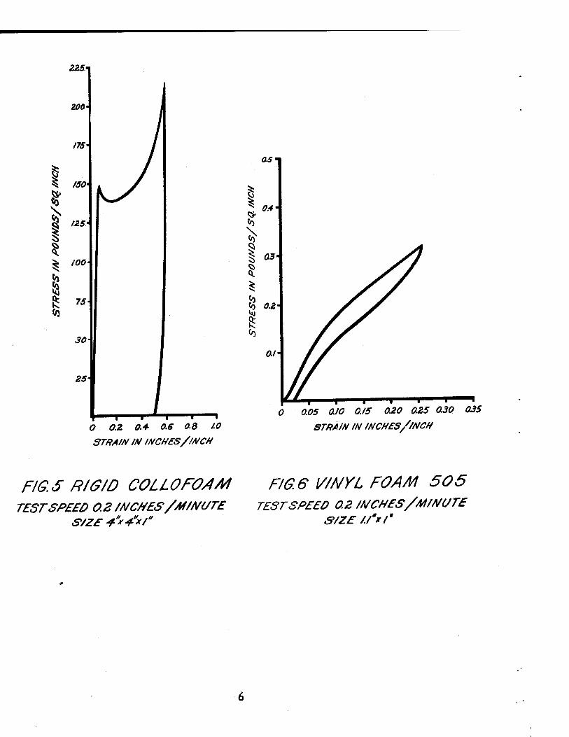
Since it was observed that a semi-rigid polyurethane foam would dissipate more energy than a flexible polyurethane foanij, the assumption follows that a rigid foam should dissipate more energy than a semi-rigid foam. Hence, a rigid polyurethane foam was investigated for its cushioning properties. Sixteen samples of rigid Collofoam were compressed to a bottoming point at 55 percent deformation. In all tests, the foam packed into a firm mass instead of disin- tegrating upon compression. As a result^ the stress (Figure 5) continued to rise with further crushing of the sample. The amount of energy dissipated is relatively high and the resilience very low. Thus, data obtained from the statie tests indicate that due to the high maximum stress, rigid Collofoam might not be a suitable energy dissipator for all of the items that are pre- sently being considered for aerial delivery. However, as the energy dissipated is quite high, this foam may be a suitable cushion for items with high fragility limits. In addition, since the density is quite high and the foam packs quickly upon compression, a lower density material would be more suitable as a cushion since it would not pack or bottom until a higher percent of the initial volume of cushion has been deformedo
■Section B
Flexible Vinyl Foam
Vinyl Foam 505.
Along with the polyurethane foams, flexible vinyl foams have also been commercially used in cushions and as an insulating material. Since static laboratory tests have shown that some polyurethane foams may be potential energy
ZZ5
STRAIN IN INCHES/INCH
0.05 aiO 0.15 020 0£5 0.30
STRAIN IN INCHES//NCN
035
FIG. 5 RIGID COLLOFO/IM TEST SPEED 0.2 /A/C//ES/M/A/UTE
S/Z£ +"*S*/U
FIG. 6 I//A/VL FOAM 505 TEST SPEED 0.2 MCHES/M/A/UTE
S/ZE /./'*/'
dissipatorsj, a -vinyl foam was tested to determine whether it should be con- sidered as a cushioning material. Twelve samples of Vinyl foam 505 were com- pressed to a deformation of 25 percent» The values obtained for the maximum stress and the amount of energy dissipated are very low while the resilience is extremely high» This is demonstrated in figure 6 where the area under the hysteresis loop is very small and the unloading curve is similar to that of the loading curve. Therefore, Vinyl foam 505 is too resilient to serve as an energy dissipator as the initial weight of the item to be cushioned deforms the foam considerably,,
Semi-Rigid Vinyl Foam
Flutterstock
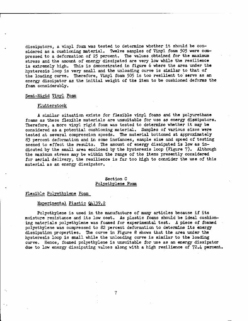
A similar situation exists for flexible vinyl foams and the polyurethane foams as these flexible materials are unsuitable for use as energy dissipators«. Therefore9 a more vinyl rigid foam was tested to determine whether it may be considered as a potential cushioning material0 Samples of various sizes were tested at several compression speeds. The material bottomed at approximately 83 percent deformation and in some instances, sample size and speed of testing seemed to effect the results. The amount of energy dissipated is low as in- dicated by the small area enclosed by the hysteresis loop (Figure 7)<> Although the maximum stress may be within the range of the items presently considered for aerial deliverys the resilience is far too high to consider the use of this material as an energy dissipator,.
Section C Polyethylene Foam
Flexible Polyethylene Foam
Polyethylene is used in the manufacture of many articles because if its moisture resistance and its low cost« As plastic foams should be ideal cushion- ing materials polyethylene was foamed for experimental test, A piece of foamed polyethylene was compressed to 82 percent deformation to determine its energy dissipation properties. The curve in Figure 8 shows that the area under the hysteresis loop is small while the unloading curve is similar to the loading curve. Hences foamed polyethylene is unsuitable for use as an energy dissipator due to low energy dissipating values along with a high resilience of 72,4 percent«
ns-i
*i i i i ii i a» as A4- as as or OB a» to
STRAIN IN INCHES/INCH o az a* as as a STRAIN m mOtO/OBM
F/G. 7 FLurr£ftsroc/< TEST SPEED 02 ///C#E$/iH/A/OT£
S/Z£ /jr^V
F/G. 8 EXPERIMENTAL PLAST/C Q 4/39.2 TEST SPEED 2 /NCHES//HWU7E
S/ZE 3S'*3.S'*/'
Section n Polystryene Foams
Commercial Polystyrene Foam
Styrofoam 22
The commercial uses of Styrofoam 22 are many and varied. Since it is a rigid thermoplastic material, resistant to moisture and a poor heat conductor, it is used for low temperature insulation. In addition, its low density of 1.6 lbs./cuofto and shock absorbing characteristics makes it a useful packaging material» Hence, since it is rigid, lightweight, and absorbs a certain amount of shock, Styrofoam 22 was investigated as a potential energy dissipator. A total of 150 samples of various sizes was tested at several compression speeds. In many instances, a change in testing speed effected the results. Disregarding the effect of speed, values of stress, energy dissipation, and resilience are shown as averages in table I0 The phenomenon was noted, that, regardless of the initial thickness of the foam sampl«, the stress and energy dissipation values per unit volume are identical at the same percent of deformation. For example, at 30 percent deformation, the maximum stress for each thickness is the same although obviously, the one inch thick samples were deformed only 0.33 inches while the five inch thick samples were compressed 1.67 inches. This observation would seem to indicate that if the stress and energy dissipation values per unit volume were obtained for one thickness at different amounts of compression, identical -values might be obtained for different thicknesses of the material at the same percentage of deformation. The tabulated data and the curve depicted in Figure 9 shows that the maximum stress is fairly constant only to 50 percent deformation so that the curve is essentially rectangular in shape. Upon further compression to 80 percent deformation, the stress rose to about twice its initial value indicating that only one-half of the cushion thickness could be utilized efficiently. Hence, static tests show that Styro- foam 22 may be considered as an energy dissipator since the resilience is low and the stress is well within the desirable range of values.
rene. Foam
Sytrofoam 33 is a rigid self«extinguishing polystyrene foam that is tinted blue for purpose of identification. Since its density of 2 lhs./cu.ft. is greater than that of Styrofoam 22, the foam was tested to determine the differ* ences in stress and energy dissipation values. In all, 137 samples of various sizes were tested at several speeds. It is öoted that the speed of testing is significant only in some instances. A comparison of the curve obtained fox* Styrofoam 33 (Figure 10) with that of Styrofoam 22, (Figure 9) shows that the two materials behave similarly under compression. The averaged data in Table II shows that here, too, regardless of the initial thickness of the sample, the stress and energy dissipation values per unit volume are the same providing the percent deformation is identical although the total amount of deformation is different. The average values of stress and energy dissipation are slightly higher than those obtained for Styrofoam 22 while the resilience remains the same. Hence, Styrofoam 33 may also be considered a potential energy dissipator since the resilience is low and the stress is within the range of desirable values.

TABLE I
STYROFOAM 22
Deformation Thickness Maximuta Energy dissi- Energy dissi- Resilience stress pated per pated per
initial vol. crushed vol.
% in. lbs./in2 in.lbs./in.3 in.lbs./in. %
30 1 32.5 6.17 21.6 11.3
30 2 39.1 8.79 30.1 8.30
30 3. 34.0 8.05 26.6 6.93
30 4 35.1 8.58 28.9 6.34
30 5 33.5 8.31 28.7 5.36
50 1 37.4 13.2 27.9 7.21
50 2 43.9 17.2 35.1 5.08
50 3 38.7 14.9 30.0 4.70
50 4 40.6 15.3 30.8 5.93
50 5 36.2 15.8 31.7 3.25
75 1 59.3 24.9 30.6 3.78
80 2 114 35.1 42.6 2.03
80 3 93.2 29.8 37.4 4.65
80 4 86.8 30.0 37.5 3.10
80 5 87.7 28.0 35.1 3.80
10
I0&-
STRAW/A/A/CH£S//HC/f
F/G. 9 STVfiOFOAM 2B TESTSP£££> 0.2 WCH£S//M/A?Ur£
S/ZE4'X4"M4'
/so-.
STRAIN /N /NCHES//MCH
F/G./O STYftOFOAM TEST SPEED 2/NCHES/M/A/t/TE
S/ZE4"x4"x5"
11

TABLE. II
STIEOFOAM 33
Energy dissi- Energy dissi- Deformation Thiclcness Maximum pated per pated per Resilience
stress initial vol. crushed vol.
% in. lbs./in.2 0
in.lbs./in. in.lbs./in. %
30 1 40.1 9.16 31.7 7.43
30 2 45.6 10.4 34.0 6.82
30 3 36.3 8.51 28.8 9.08
50 1 46.3 18.2 36.9 3.47
50 2 50.7 20.8 42.2 2.74
50 3 48.9 17.1 34.5 7.01
50 4 51.5 20.3 43.1 3.08
50 5 48.6 I606 33.3 7.46
75 1 71.9 31c4 42.3 2.89
70 2 61.4 30.5 44.1 2.27
80 2 256 42.4 53.0 1.84
80 3 117 35.8 44.5 2.51
80 4 111 360O 45.3 2.69
80 5 107 33.9 42.6 2.20
12

Experimental Polystyrene Foams
Experimental Plastics Q103.15 and Q1Q3.21
Since tests on low density rigid polystyrene foams indicated their possibility as energy dissipatqrs, an investigation was conducted on a higher density foam to determine the effect af density upon the properties of the cushioning material during compression. One hundred and twenty nine (129) experimental plastic (Q103.15) samples, and twenty six (26) experimental plastic (Q103.21) samples of various sizes were tested at several compression speeds. The bottoming point of both materials was reached at 60 percent deformation, Again^, disregarding the effect of speed which appeared to be significant in some instances, the averaged data is shown in table III. Similarly to the Styrofoams, different thicknesses of 3 lbs./cu.ft. density, experimental plastic Q103.15 were found to have the same unit energy and stress values at the same percentage of deformation. Figures 11 and 12 show that both materials deform similarly under compression with a relatively constant stress and a small amount of resilience. From the tabulated data, it is noted that the stress and energy dissipation values of 4 lbs./cu.ft. density experimental plastic Q103.21 are higher while the resilience remains the same than for the lighter material. It is concluded that both of these foams may be considered as potential energy dissipators because of their high energy dissipation value, constant compressive stress and low resilience.
Expandable~In-Place Polystyrene Foam
Experimental Plastic Q865.2
Experimental plastic Q865.2 is a foamed-in-plaee polystyrene that is ffcraish- ed in the form of small beads containing an expanding agent. Upon application of heat, the material may be expanded to any density, shape or size desired^ Since the foam can be easily fabricated and only the beads need to be shipped to the point of use, the cost of transportation is low due to decreased bulk.. Moreover, as the foam produced has many of the characteristics of Styrofoam, experimental plastic Q865.2 was investigated for use as an energy dissipator. Six samples of 1.7 lbs./cu.ft. and four of 4.4 lbs./cu.ft. densities respec- tively were measured. The lower density material was compressed to a bottom- ing point of 70 percent and the heavier foam to 60 percent deformation. The data obtained (Figures 13a and 13b) show that the stress and energy dissipation values increases with density while the resilience decreases. Although the stress of the lighter material is within the fragility range of the items cur- rently considered for aerial delivery, the resilience is too high for the foam to be effective. On the other hand, while the resilience of the heavier mater- ial is low, the stress increases almost threefold. Thus, its applicability depends entirely on the fragility limit of the cushioned items since the stress is barely within the range of desirable values.
13

TABLE III
EXPERIMENTAL PLASTIG-0X03.15
Energy dissi- Energy dissi- Deformation No. Thickness Maximum pated per pated per Resilience;
Tested stress initial vol. crushed vol.
an. lbs/in in.lbs/in. in»lbs•/in• «„ 3 %
30 24 1 83.1 15.6 55.3 5.65
50 24 1 90.1 33.7 69.2 5.07
30 24 2 85.0 19.2 65.3 4.99
50 24 2 89.4 36.6 74.8 3.42
60 24 2 104 44.9 76.2 3.95
75 9 2 153 65.2 93.5 1.78
EXPERIMENTAL PLASTIC Q103.21
Percent Energy dissi- Energy dissi- defoiv No. Thickness Maximum pated per pated per Resilience mation Tested stress initial vol. crushed vol.
% in. lbs. /in^ in.lbs/in.3 in.lbs ./in.3 %
30 6 2 148 36.4 123 6.96
50 6 2 173 74.5 150 4.61
55 4 2 175 73.4 135 7.52
60 6 2 195 86.3 145 5.34
70 * 2 244 101 109 10.8
1U

BZSt
rrr-t
ae
I
i 65
as-
MO-
TS'
so-
STRAIN IN /NCHES//NCH STRAW IN INCHES/WCN
F/G.ll EXPERIMENTAL PLAST/CQ /03J5 TEST SPEED 2 JNCHES/A4 MUTE
S/ZE 4"x4"x2"
F/G./2 EXPERIMENTAL PLAST/CQ /03.2/ TEST SPEED 2 /NCHES/M/AfUTE
3/ZE 4m*4'*2'
1$
90-,
0 0.2 0.4- 0.6 0.8 /.0
STRAW /A/ INCH£S//MCH
I I
0 0.3 04 0.6 0.S 1.0
STM/N /HINCHCS//MCM
F/G./3A EXPERIMENTAL PLAST/C Q 865.2 TEST SPEED 2 /NCHES/M/A/VrE
S/ZE •«tW.r/* D£NS/ry. 21BS./CU/7-.
F/G./3B EXPER/MEA/TAL PLAST/C Q 865.2 TEST SPEED Ö.2 /MCHES/M/W(/r£
S/Z£*"x-4-*x2* DENSJryj 5LBS./CUfr
16

Section E Acrylate Foam
Rigid Acrylate Foam
Foamed Plexiglas
Since it has been established that rigid plastic foams may be used as energy dissipators, the performance of an acrylate foam as a cushioning material was investigated. Nine samples of experimental foamed Plexiglas were tested at various speeds to a bottoming point at 50 percent deformation. In all cases, speed of testing seems to have no effect upon the data. Although the resilience is low and the area under the curve (Figure 14) is quite large so that foamed Plexiglas appears to be a potential energy dissipator, the maximum stress obtained is far above the fragility limits of the items presently considered for aerial drop. This may be due to the fact that the minimum density available was 8.0 lbs./ft.3.
Section F Epoxy Resin Foam
Rigid Epoxy Resin Foam
Eccofoam FP
With the development of foamed-in-place plastics, Eccofoam FP, a foamed-in- place liquid epoxy resin was investigated for its properties as a potential energy dissipator. Three one-inch cube samples of 17 lbs./cu.ft. density were compressed and the bottoming point reached at 68 percent deformation. Although the foam ex- hibited zero resilience and the curve (Figure 15) is partly rectangular in shape, it is not suitable as an energy dissipator for the items currently considered for aerial delivery due to its extremely high stress value and high density.
Section G Glass Fiber
Resin Impregnated Glass Fiber
Fiberglas Honeycomb
The use of paper honeycomb as a cushion in field tests indicated that a honeycomb type material may be an effective energy dissipator. Hence, considera- tion was given to a resin impregnated glass fiber with a honeycomb structure.
17

300
0.1 0.2 0.3 0.4 0.5 0.6
STRAIN IN INCHES//NCH
0.7
F/G. /4 FOAMED PLEXIGLAS TESTSP££D 2 /NCHES/M/A/UTE
S/ZE / "*/**/'
4500-t
4000-
0 0.2 0.4 0.6 STRAIN IN INCHES//NCH
F/GJ5 FCC O FOAM FP TEST SPEED 20 /A/CtfES/M/A/l/TE
S/Z£ /"x/"x I"
18

This material is more rigid than paper honeycomb and might give a higher stress and energy dissipation value per unit volume. Five cubic samples were compressed to a bottoming point at 90 percent deformation. Figure 16 shows that Fiberglas honeycomb deforms similarly to paper honeycomb and the curve obtained is fairly rectangular in shape with a constant stress until a very definite bottoming point is reached. Resilience is negligible in all tests. The tests indicate that Fiberglas honeycomb may be considered as a potential energy dissipator because of high energy dissipation value and constant stress during compression.
PART III INORGANIC MATERIALS.
Introduction
Many types of inorganic materials have been used for the same applications as foamed plastics. They have been employed as structural materials as well as shock absorbers in packaging fragile items because of their high compressive strength and rigidity. They have been used extensively as insulating materials due to their heat resistant properties. A consideration of their compressive strength and rigidity properties made it appear advisable to determine whether a number of inorganic materials are potential energy dissipators for use in high velocity aerial dropse
Section A- Silicaeous Materials
Fibrous Fireproof Silicate Blocks
Asbestos Blocks
Previous static laboratory tests had shown that materials with honeycomb type structures have a tendency to crush with a relatively constant stress. This was observed in tests made on aluminum^, fiber giass^ and paper honeycombs where the cell walls tend to crinkle upon compression. Thuss it follows that tests should be made on materials with cell shapes other than hexagonal in order to determine whether they crush in a similar manner. Eight asbestos blocks (Figure 17a) were compressed to a very definite bottoming point at 70 percent deformation. In all cases^ resilience is negligible since the samples break down and finally pack into a firm mass (Figure 17b)0 The curve in (Figure 17c) corroborates the fact that although the asbestos blocks do not have hexagonal shaped cells? the rectangular shaped compression curve obtained is similar to that for a honeycomb material in that the stress is relatively constant with a definite bottoming end point. Since no knowledge of the effect of sample facing was availables tests were made using two unfaced samples stacked on top of each other to form a block. During compression, the specimens telescoped into each_
19

250t
Jf
1
CD
200
/SO
100
0.+ 0.6 0.8 1.0
STffAtN tN /NCHES//NCH
F/G. /ff F/BEßGLJtS HONEYCOMB TEST SPEED BO /NCHES/M/A/L/TE
S/ZE 3"xj"xj"
20

•*ikA
Figure 17a - Asbestos blocks before compression.
Figure 17b - Same asbestos blocks as above after being compressed to a very definite bottoming point at 78 percent deformation. Resilience is negligible since sample breaks down and packs into a firm mass.
21

0.2 0.4- 0.6 0.6
ST/?A/A/M WCHES/WCH
FIG. /7C ASBESTOS ßL OCXS TEST SPEED 20 INCHES/Al/NUTE
S/ZE 4"x4"x4"
22
55 ? ?
i*1 $
MOM 2?& /S0A//)Oc? M &S3&J.S
23

other to form a very dense mass"before actual crushing occurred. This is observed in Figure 17d where the «low constant force depicts this telescoping action and th« abrupt rise in force to almost twice its value depicts the actual crushing of the sample. Hence, all the pieces have only a 50 percent deformation since the density doubled» These tests show that although asbestof blocks do not have hexagonal shaped cells, they behave similarly to1 honeycomb material in that they deform at a relatively constant stress. Hence, in spite of high density, this block material may be considered as a potential energy dissipator since the values obtained are within the prescribed limits. However, if layers of blocks are used, a facing must be employed as each block tends to telescope.
Hydrous Calcium Silicate Blocks
Kaylo and Kaylo-20 Block Insulations
Samples of Kaylo material, a rigid hydrous calcium silicate heat insulator reinforced with asbestos fibers, were static tested since actual free-fall drop tests made by the manufacturer seemed to indicate that the material may be a good energy dissipator. In these tests, items such as canned foods were packed in cartons lined with Kaylo material and dropped from a height of 1000 to 1500 feet onto a concrete runway. A few cans ruptured while a few were dented. An investigation was conducted on two types of blocksj Kaylo and Kaylo-20. Both materials were compressed to a bottoming point at 69 percent deformation. Al- though resilience is negligible with high energy dissipation values, the density and stress for both materials are above acceptable limits to consider their use as energy dissipators.
Commercial and Experimental Foamglas
A number of materials tested shows that different types of rigid foam in- sulating or sandwich core materials may be good energy dissipators. Hence, Foamglas was selected for static testing since it is a unicellular fire-proof material that is used extensively in insulation and construction work. Twenty- seven (27) samples of experimental Foamglas, Ö lbs./cu.ft. density and two hundred and ten (210) samples of commercial Foamglas 9 lbs./cu.ft. density were tested in various sizes at several speeds to a definite bottoming point at 85 percent deformation. It is observed from the curves in figures 19a and 19b that the stress increases gradually with deformation until a maximum is reached at about 50 percent deformation. Upon further compression, the stress declines until a bottoming point of 85 percent deformation is reached. A cursory statis- tical analysis was made from the data in tables IV and V on the effect of speed of testing, density of material, sample size and thickness upon the stress and energy dissipation values. This analysis shows that the density of the material
2k

TABLE IV
COMMERCIAL POAMGLAS
Testing speed
No. tested
Sample size
t Maximum stress
Energy dis- sipated per initial vol.
Energy dis- sipated per crushed vol.
Resilience
inches/mil a. in. lbs./in« in. lbs. /in. * in.lbs./ifl.3 %
0.2 10 3x3x1 191 113 W 0
2 10 3x3x1 176 10$ 124 0
20 10 3x3x1 232 130 158 0
0.2 10 3x3x2 207 141 161 0
2 10 3x3x2 228 149 172 0
20 10 3x3x2 231 158 181 0
0.2 10 3x3x3 197 131 152 0
2 10 3x3x3 230 149 173 0
20 10 3x3x3 230 152 176 0
0.2 10 4x4x1 169 102 121 0
2 10 4x4x1 180 107 127 0
20 10 4x4x1 209 128 148 0
0.2 10 4x4x2 145 102 118 0
2 10 4x4x2 162 113 130 0
20 10 4x4x2 185 124 145 0
0.2 10 4x4x3 215 151 172 0
2 10 4x4x3 206 140 160 0
20 10 4x4x3 214 147 171 o 0.2 10 4x4x4 194 136 154 0
20 10 4x4x4 186 140 160 0
25"

TABLE V
EXPERIMENTAL FOAMGLAS
Test speed inches/min 0.2 2 20
No. tested 9 9 9
Weight 2.30 2.36 2.40 oz.
Width 4.00 3.99 3.58 in.
Length 3.98 4.01 3.98 in«
Thickness 2.01 1.95 1.99 in.
Density- 7.80 8.21 8.29 lbs./cu.ft.
Maximum force 1968 2781 2593 lbs.
.Maximum stress 124 174 163 lbs./sq»in.
Energy dissipated 2463 3403 3425 in.lbs.
Energy dissipated per initial volume 76.9 109 109 in.lbs./cu.in.
Energy dissipated per crushed volume 89.4 126 126 in.lbs./cu.in.
Resilience 0 0 0 percent
Final force 474 733 756 lbs.
Final stress 29 08 45.8 47.7 lbs./sq.in.
Deformation 1.73 1.68 1.72 in.
26

400-t
1
!
ft
I
700-t
600-
SOO
400-
300'
200-
0 0.2 0.4-
STRAW tN INCHES/INCH
FIG./8A KAYLO BLOCK TEST SPEED 2 /NCHES / M/MUTE
$/Z£ 3*x 4'x A3"
0.2 0.4- 0.6 0.8 STRAIN IAI INCHES/INCH
F/G./8B KAYLO-20 BLOCK TEST SPEED 20 WCHES/M/HUTE
SAMPLE S/ZE J'x+'xtf"
27
2«S
Äff-
I I
0 OJ 04 JU A* AS 0.6 AT 0.8 M IJ)
STM/N mmCBBS/JNCH
F/G/9A EXPEft/MENTAL FOAMGL/IS TESTSPEEO 20 /f/CHES/WNUTE
SIZE «#"*<*•**»
STRAIN m /neues//Mm
F/GJ9B COMMEffC/AL EOA/HGLAS TEST SPEED ZO /HCHES//UMUTE
S/ZE 4'*<Aa'
28
has no significant effect upon stress or energy dissipation value. However, Foamglas is very brittle and crumbles readily and hence this observation may not be valid due to the fact that while the two samples tested have nearly equal densities the foam structure varied considerably. A much lighter Foamglas of 3 to 4 lbs./cuoft0 density should be tested to determine the effect of density. In all cases, speed, sample size and thickness are quite significant. The stress and energy dissipation values increase with higher testing speeds and greater sample thickness. On the other hand, these values decrease with an increase in sample size. At present, there is no satisfactory explanation as to the cause of this phenomena. As both materials powdered upon compression, resilience is negligible. In conclusion, experimental Foamglas is considered a potential cushioning material since the amount of energy dissipated per unit volume is fairly high resilience is negligible and the compressive stress falls within the prescribed limits. The utilization of commercial Foamglas as a cushioning material is entirely dependent upon the fragility limit of the cushioned items since the stress obtained is at the maximum limit of the range for those items presently considered for drop.
Section B Metals
Foamed Aluminum
Since solid blocks of metal are far too rigid to be considered as a poten- tial cushioning material, a foamed sample of one of the lighter metals, aluminum, was tested to determine whether it is a potential energy dissipator for use in high velocity aerial drops. The foamed aluminum sample crushed well beyond its bottoming point and since resilience is negligible, all values are- calculated to the bottoming point at 69 percent deformation. Figure 20 shows that the curve is fairly rectangular in shape only to about 30 percent deformation and upon further compression, the material packs into a solid mass. The test shows that foamed aluminum is unsuitable for use as an energy dissipator because of its extremely high stress. However, for densities below 36 lbs./cu.ft., stress values may be lower. This conjecture has not been confirmed since lighter density foamed aluminum is unavailable.
Empty Metal Cans
Empty metal cans* were tested in compression to determine two things s
*Beer cans with hole punched in top„
29
5500 i
5000
4S0Q'
4000'
£> 3500
(^ 3000 •
1 ^ 2500'
R 2000 - 0)
1500'
tQOO'
500'
-I— 0.4
-1— a z o.4 o.e o.e
STRAIN tN /NCHES/WCff F/G.20 FOAMED ALUMWC/M T£STSP££D 20 WCtfES/MWUTE
S/2£ /"*/">/«?*
1.0
30

(1) potential as energy dissipators and (2) the strength of the can. These two factors are important because in aerial drop of C-rations, the stress required to initially rupture the can must be known as well as the energy dissipating capability of the cushioning material used. In this way, require- ments can be established for the screening of materials as potential energy dissipators for C-rations. The objective is to design a drop system for C- rations so that all the energy of the dropped item will be dissipated at a constant stress or decelerated at a stress value slightly lower than the break- ing strength of the can» Six empty metal cans were compressed at two test speeds to complete failure and all the stress transmitted to the base plate. During each of the tests, regardless of speedy initial failure was found to occur at the can seams. Upon further compression, a crinkling effect took place until the cans were completely crushed. Figure 21a shows an essentially rectangular shaped curve where the can is compressed at a relatively constant stress to a bottoming point at 81 percent deformation» In all cases, resilience is negligible while the stress and energy dissipation values fall within the desired limits. An extremely high initial stress of 318 lbs./sq.in. (Figure 21b) occurs at the lower test speed, while at the higher speed, the stress required to initially rupture the can is 110 lbs./sq.in. Thus, if the energy dissipator behaves similarly under dynamic testing as in static testing, the cushion re- quired would dissipate all the kinetic energy of the drop system at a constant stress equal to the initial rupture stress of the can» Calculations can be made to determine the total kinetic energy of the drop system as well as the fragility factor of the cans according to equations 1 and 2*.
KE m 1/2BÖÄ Equation (1)
wheres KE = Kinetic Energy in Foot-Pounds
m "Mass of Drop System in Weight/Gravity
? s Impact Velocity in Feet/Second
F■ = ma * Wa = WG Equation (2) g
whereg F = Force in Pounds
a - Deceleration in Feet/Second
W ~ Weight of Drop System in Pounds
g s Acceleration Due to Gravity, 32.2 Ft./Second2
G s Fragility Factor of Load in Gravities (g's)
■»Murray, G.E. - Basic Concepts on the Energy Dissipation of Cushioning Materials, Technical Report CP-12, Chemicals & Plastics Division, QM E&E Center, Natick, Mass., April 1958
31
350
ZOO-i
0.1 0.2 OS 0.4 OS 0.6 07 0.3 0.9
STRAW IN WCHES/WCH
F/G. 2/A METAL CANS TEST SPEED 20 MCHES/M/NUTE
S/ZE 2.6'* 4.8*
i i i i i i ' i i o./ 0.2 as a+ as as o.7 aa 0.0
STRAW M /NCHES//NCH
FIG. 218 METAL CAA/S TEST SPEED 2INCHES/AI/A/UTE
S/ZE 2.6S4.8"
32
However, in order to decelerate an object at a constant force without exceeding its fragility factor, the minimum permissible stopping distance must be deter- mined. This is calculated as follows?
Ss^"_:^ Equation (3) 2a £m? where? S = Deceleration Distance in Feet
¥ = Impact Velocity in Feet/Second
G = Fragility Factor of Load in Gravities (g's)
Thus a screening test can Se used to select a material which will dissipate all the Kinetic energy (KE) of the drop system as calculated from equation (l) at a constant force slightly below the fragility factor. G, in equation (2), through a distance expressed in feet that is greater than (S) as calculated in equation (3). Since an essentially rectangular shaped, high deformation curve is obtained upon compression, metal cans may be considered as potential energy dissipators. As only a few static tests were made on cans, it is recommended that dynamic tests be made on C-rations to determine their fragility factor so that require- ments can be established to select an efficient cushioning material.
PART IV WOOD PRODUCTS
Introduction
Wood and wood products are among the most widely used materials in sand- wich construction and packaging» These materials are good absorbers against shock and vibration encountered under usual shipping conditions. Therefore, these products were subsequently tested as potential energy dissipators for use in high velocity aerial drops»
Section A Balsa Wood Blocks
Tests made by the supplier show that balsa wood is a useful material in the packaging of items for transit. Hence, samples of balsa wood were tested statically for their energy dissipating properties. Speed of testing has a pronounced effect upon the data (Figured 22a and 22b). At the lower testing speed, a peak stress is obtained which drops quickly as the sample begins to break down and pack. At the higher speed, the1samples flew apart upon initial impact. Therefore, these tests show that balsa wood is unsuited as an energy dissipator since the amount of energy dissipated is very low and the bottoming point is reached at approximately 45 percent deformation.
33

3ff-i
l Ä>-
/S-
/O-
1 0 0.1 0* 0.3 0.4- 0.5 0.6
STRAIN IM INCHES/JNCH
30
0 0.1 0.2 03
STRAW IN MCMes/MCH
F/G22A BALSA WOOD BLOCK TEST SPEED 2 //VCHES//U/A/UTE
S/ZS 4"x+"x2*
FIG. 22B BALSA WOOD BLOCK TEST SPEED 20/A/CHES/M/AWFE
S/ZE 4*x<***2"
3k

EXPERIMENTAL TEST METHODS
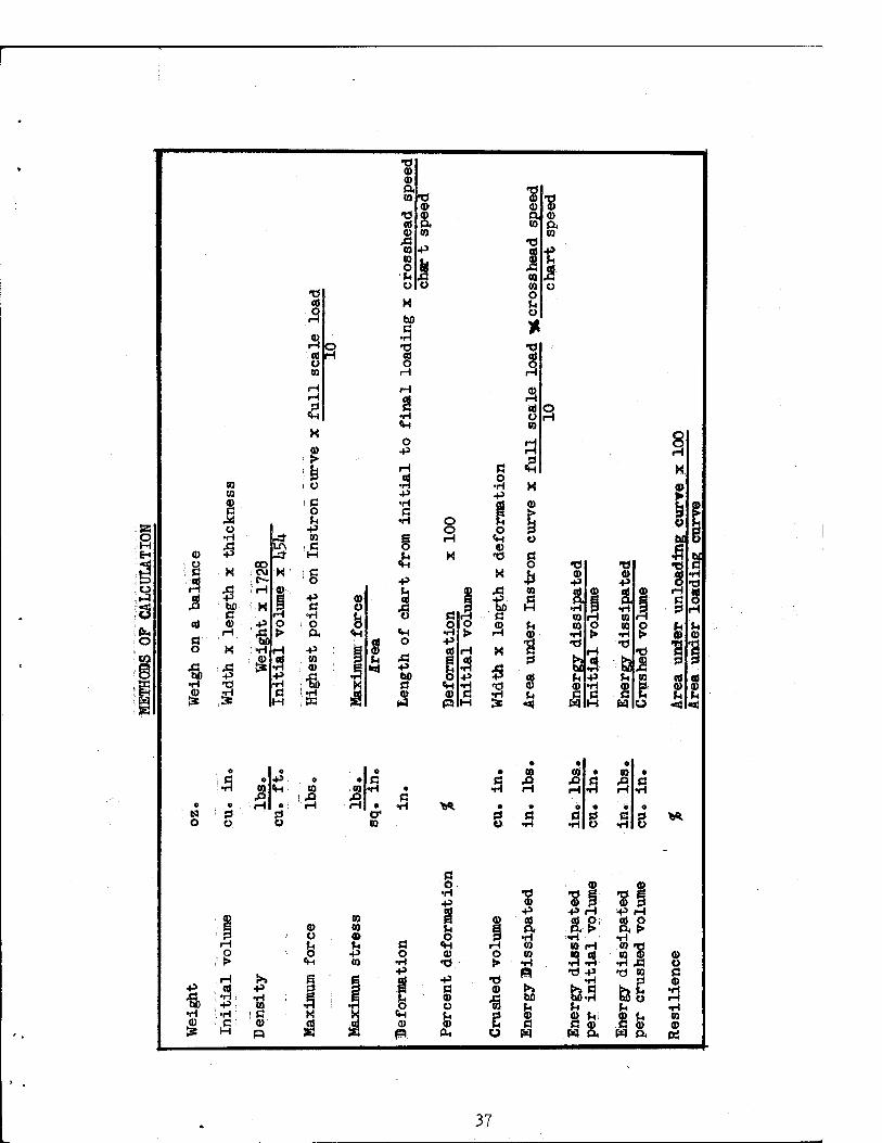
Cylindrical and rectangular foam samples of various sizes were cut and conditioned at 73o5 £ k% R.H. in accordance with ASTM procedures. The com- pression apparatus used was a model TT-C1 Instron teste? ».with a constant rate of crosshead movement. Hysteresis force-deformation curves were traced on an automatic high speed graphic recorder while the area under the curve was ob- tained with an automatic integrator operating simultaneously with the recorder. As some of the honeycomb materials have large open cells and do not represent a uniform cross section, four inch square samples were chosen and is the maxi- mum sample size that the testing apparatus can accomodate. However, earlier tests were conducted to determine the correct sample size and speed as well as to investigate foams as potential energy dissipators. Various size samples were tested at speeds of 0.02, 0.2, 2, 10, and 20 inches/minute.
PROCEDURE FOR PREPARING AND TESTING SAMPLES UNDER COMPRESSION
lo Preparation of Samples
a. Condition samples at 73.5 £ 2°F. and 50 £ h% R.H. to constant weight.
bo Number and measure the width, length and thickness of each sample.
c. Weight each sample.
2. Testing Apparatus
a. A constant rate of crosshead speed compression tester equipped with cycling controls and a recording device for tracing hysteresis stress- strain or force-deformation curves.
b. An automatic integrator that records the area under the curve as it is being traced while not absolutely essential, is very helpful in minimizing the amount of work involved in the final calculations.
3« Procedure
a. Compress one sample at 2 inches/minute speed to the greatest amount of deformation to which the sample can be subjected. The deformation point at which bottoming occurs is located on the curve and in addition, the initial peak force is also obtained.
35

b. Set the crosshead cycling controls so that the crosshead will compress a sample only to the bottoming point as obtained in 3a above«
Co Compress the rest of the samples to this predetermined amount of de- formation at 20 inches/minute speed.
Calculations
a. Record for each sample the weight, width, lengthy and thickness. From the curves obtained, tabulate the maximum force, energy dis- sipated, deformation, and initial peak force, if any.
bo From the data in 4a, calculate the density, maximum stress, energy dissipated per initial volume, energy dissipated per crushed volume, resilience, and initial peak stress, if any.
DEFINITIONS
"Bottoming" is said to occur when the sample has failed completely under compression at a very definite end point at which under further compression the stress increases rapidly with little or no further deformation. For materials which do not have definite compression end points, bottoming occurs where a 100 percent increase in force increases the deformation by less than 2 percento (ASTM Tentative methods of testing package cushioning). This may be different from other definitions of "bottoming".
Resilience is the ability of the cushion to recover its size and shape after deformation. It is expressed in percent of the ratio of the energy returned to the energy applied to the load upon impact. Thus, the resilience is 100 percent for an ideally elastic impact and is zero for an ideally in- elastic impacto
36
a>
8 •A
§
co to
8
3 bo C a>
i-i
oo CM
■Si-
xi ja •H T) .2 Sd
b£ ■r-P
5
Q
P
(0 Q
<S
£ i o
!§ P 0}
. ß
g P c
■ O P. p CO CO ,ß •H
(D CJ
B
5
(0 CO a CO
T) CO
CO to o
o
X M ß
'S
o p
43 p •H c
8
1 o
p bO ß
CO CO D. CO
Ü
o Q
M
ß
p
o CD
Cfi
o
P
8
0 M I
CO p
JJ CO CO
be
8
ffi
"b CO p
1 to CO
•H
ß c
I 5
43 Ö.8 *
u
to o
CO X)
P
g
co CO
co •W.
g
CO • •
to • to 5 s
e « ■ «
ß SJ ß •H o •H
**.
ß
p
I •ö. p ß CD O
& PL,
H O S>
•O CO
-a
CD P
CO
CO to
bO fa CD fi W
37
COMPARISON AND DISCUSSION
The data on all the materials tested is tabulated in Table VI« An average value of all tests is shown when only one size of sample was tested at one speed but the maximum and minumum values of the ranged results are tabulated when various size samples were tested at several speeds. Since the aerial delivery of C=»rations is important, the numerical values obtained for the strength of the cans under the higher static testing speed is used as a basis to screen other materials (Table VI). These measurements are informative because dynamic tests have not been made to determine the strength of the metal cans in order to establish the criteria for the selection of a suitable cushioning material for delivery of C-rations» In accordance with the numerical values given for the cans^ all the materials are grouped into three classes? (l) those which have definite potential as energy dissipators since they fall within the re- quired range of metal can valuesj (2) those which appear to be on the border line of the other two classesj and, (3) those whose values are too low or too high and consequently can be eliminated since there is no possibility of their being considered as cushioning materials for aerial delivery of C-rations0
Class (3) indicates that thirteen different materials are unsuitable for use as energy dissipators for C rations. Since felt, polyester urethane, Vibra- foam 41255 and vinyl foam 505 are so soft that they deform readily upon contact, the stress and energy dissipation values are too low and the resilience too high for their consideration as cushioning materials. While balsa wood blocks are fairly rigid, they are eliminated because of their low energy dissipation values. Although the stress of experimental polyethylene foam (Q4139.2) is within the desirable range of values, the amount of energy dissipated is low due to the high resilience of the foam. On the other hand, the stress values for foamed flexiglas, Eccofoam FP, Kaylo, Kaylo-20 blocks and foamed aluminum are much greater than the desired values. However, it may be noted that in each of these cases, the density is also extremely high. Thus, at lower densities, the stress values may be less so that the materials may possibly be applicable in aerial delivery work. Although the lighter density experimental plastic Q865.2 foam and Flutterstock are fairly rigid materials so that their stress and energy dissipation values fall within the prescribed limits, these foams are eliminated because of their high resilience» Based upon the above criteria, only eight out of 25 different materials tested merit consideration as energy dissipators. Semi-rigid Collofoam, Styrofoam 22, Styrofoam 33 5 experimental plastic Q1Q3.15 and Fiberglas honeycomb are in group 1 and dissipate a fairly large amount of energy with little or no resilience. Moreover, since the stress is slightly lower than the breaking strength of a metal can, these five materials have the best potential as energy dissipators in the aerial delivery of Gyrations. Although asbestos blocks and experimental Foamglas have no resilience and high energy dissipation values, their stress range
38

1 •H
fi o 1 i
CO CO
■A o
-p
8 rlHHKHHriHNNNW^in^^in^^n^ini^iArt
1
<D n
ß O •H -P
1 «A O O O Q P COXA H 1A Q Q XA ©XAXAXAf*> CM Q O CO: OS Qv Os XA
OOOOCOSD Os< C^eOCOXAsO C-CO XACM CM CM CO CO S0 1TWO O VD >OjJ
S £ CMM3 0 0CM ;0 Vft0^tOHt>-0\OsHcof-0 •H \ * . • . . O «CM • • » • * « • . . * . • P"? .it .it SO
c*Srt CM f^JHcO H vO_=J_^ Os ONCM c^voi nrf^oOrlflH^ r- 0) ß CD P
CO
H OQXAOsP- P- XA HCOIAAION CO sO 1 f^HJCO O XA -S • • • • » CM P- . « « • » . NjnV\H • .
CD >0_=T CM:XA XA ,0. fncOsO t-_=f XA iXA 0
•H 8 w. (III II 1 1 I 1 1 1 1 '©;c\01V\ CM_=f--t O H O-=fc"V-=r00s0 XA
s CD CM O CM: 0\ SO C\ XA ••»•••• CO P- •H .... .; •; . i VTv CM Os XA cs, CM r-■ • , »
« H lACMCMr^OOOO-^tACMO fn-d"lA"lAVA p- H f"\ O O O O CM
'' 1 fc H 'S.
0
•H a £ 3 OvOf^CM OOOCMmiCM C*\ Q a... vO P- p- cs. H » . . -Ö XI • -d1 CM XAsO WeOf^ !U\H ••••>■ cr\ so
B 1 II 1 r-l H r-i r-i I T T T 1 H 1 OsO CS.CM _d II 1 I 0">CMXASOXACM m 1 C—sO
W iJ 43 f* cd § H co a • • . . . l> OS • H OsXA P-CQ CM CN.CM O »H »4WOH'>"^
r^O CM CKUVf^OsO O-Sf O R » o • *^t .1 H msO Os CM■ <*\ • CM (^^JvO HiHco rtrtfliH H CM o O O CM-^fs HNWHHvO
C .H U ß W CO o •rl
H 1 U H CM t> CO CD o ß <*\
•H a. >• •H o H o os CM CM t- cMr-eooos o so p V, * ... Os • * * so Ho . . . XA
3 PQ
>» CD bo-P
H « 2
P-XASOJ QCMXA pseo » •■ • o Os H » CMrr\r<-\3 HOOCO hlftCMOO I CM P- -^ I 1 1 1 III 1■H | | IJ- 1 1 1
O OslAt— OsO CO CS. CM 1 CM CMSO H SO Os P- CM Os XA *Jl U a) ■P H 6< •H . • • . »\AOs . * . . . CM H O O O • <*\ » «CO <*% • f»\ P-
ß -H &q co
ß ß •H
Os-^iQ f>-4'OsOcO QO,<*)P * . o »CO .HP-H;00\SO • rH CM cncniH H p-OOSO CO SO H H O OOH «*> CM sO 1A CM SO OS rH
1 ra M ^ CMJ'CO f~ «^ oJt--5t »c^OXAsO •
«nHHQ _^CMCO \ACMQ * . • CO XA H OsHHH p-sOCM '^^nHHOfl i-d e*\
1 i 1 • 1 Hrt(M CM CM 1 1 1 7 1 CM 1
fs CO ß •H CD •H X u \ d ■p . JJ f^-sr H iiii ii fnso os P~SO CM H i os <*VCK
• • • «, Os CM.-^fr OHiXACp V\ •P-P-'C'S, . • »sOp-OCMO * O OsHiCÄCMfHCMXAOs Os r=-_a,P- • • »0O-=r f»\r^sO Os-StCO H p-^XAsO OsH'H H H H H H H r4 Q 0:0 P-TXA P- CM H XACM en CM
4
CO CO ■R i-i)
XA H CM H CM CM »CM . . . Os •
C*X C^JXA C\XA O QsO • iHsO
CO so cd o o o o a -H ^» H i-f; iH CO «H 'H O 4» g bO +i -P q) <D 43 4»
«H co S e W, CO H ß COCO CO
H ft. «X >S fz, S ft, ft, a) -P XAXA ft. ft. H ^J P O O ß O O ; O CD CM O 00 O ß H OWnri OOH «M H H fc t,HU\üHHH OHCQ
ca H
45 u
««ig
id
ofpa
m 2
of p
am 3
ri
meh
ta
rgla
s H
stp
s B
l ri
men
ta
1 C
ans
d C
öll
o
rim
enta
ri
men
ta
erc
ial
est
er
U af
oam k
IF
oam
te
rsto
c
rim
enta
ri
men
ta
ed P
lex
foam
FP
o B
lock
o-
20
Bl
ed A
lum
a
Woo
d
- 1 "D H N CD ffl'.ICD CD W Mi CD CD. B -P >, U >. 43 CD CD «a OHH g CO
cococoWP^^W*«wwofaft.>>f^wwp^cjq«u:fcm
39

is just within the breaking strength of the cans. As no knowledge is available on whether filled cans have higher or lower breaking strength than empty cans, these materials are classified as potentially suitable for use. Based on this assumption, empty metal cans are also placed in this category. Eigid Collofoam, experimental plastic Q103.21, higher density experimental plastic Q865.2 and commercial Foamglas form the second group of materials whose stress range is approximately equal or slightly above the breaking strength of the cans. Thus, utilization of these materials for energy dissipation is entirely dependent upon the fragility factor of the C-rations. However, even if these materials were found to be unsuitable for use with C-rations, they may be considered as potential energy dissipators for drop items with higher fragility factors because they exhibit little or no resilience and dissipate a large amount of energy per unit volume. Hence, a careful analysis of the data indicates that density plays a significant role in determining the resulting numerical values since the stress and energy dissipated increases with density» In addition, the data shows that cellular and foamed materials are better energy dissipators than solidly packed materials« This is due to the fact that each layer of cells or foam offers the same amount of resistance to compression, or stated in other terms the uncrushed portion of the sample remains relatively constant in density during compression until completion of,the test or until bottoming occurs and the crushed portion packs. An analogous situation exists with materials composed of vertical colTimns of cells such as honeycomb where upon disintegration, a crinkling of the cell walls takes place under compression. Nevertheless, consideration must be given to the fact that even though some of the materials tested may be good energy dissipators, there remains the important questions of transportation, bulk and cost since many of the cushioning materials tested herein cannot be manufactured in the field.
ko

CONCLUSICMS
Cellular and foamed materials have better energy dissipation characteris- tics than solidly packed materials since the eompressive stress is more uniform. In many instances, static compression tests show that speed of testing, density, thickness and size of the test samples nay be significant in determining the final stress and energy dissipation values.
KECQMMENDATICMS
1. Further investigation to determine whether Fiberglas honeycomb can be prepared in the field.
2« Further investigation of low density acrylate and epoxy resin foams.
3o Investigation of metallic cylinders as energy dissipators.
4. Standardization of the size of the test samples at 4" x 4" for static tests.
5« Standardization of the procedure for preparing and testing samples under compression.
ACKNOWLEDGEMENTS
The author gratefully acknowledges her indebtedness to George J. Merritt for his interest and guidance in the work accomplished and to Charles McHale for his assistance in the preparation of the materials used. Further acknowledge- ment is made to a number of people, also in the Chemicals and Plastics Division, for their advice and aid in the preparation of this report«
hi