zxr103900e r10 00e product description product d cripti · arranging configuration through powerful...
TRANSCRIPT

ZXR10 3900EProduct DescriptionZXR10 3900EProduct Description

ZXR10 3900E Product Description
ZTE Confidential Proprietary © 2009 ZTE Corporation. All rights reserved. I
ZXR10 3900E Product Description
Version Date Author Approved By Remarks
V2.0 2010-09-02 ZTE ZTE
© 2009 ZTE Corporation. All rights reserved.
ZTE CONFIDENTIAL: This document contains proprietary information of ZTE and is not to be disclosed or used without the prior written permission of ZTE.
Due to update and improvement of ZTE products and technologies, information in this document is subjected to change without notice.

ZXR10 3900E Product Description
II © 2009 ZTE Corporation. All rights reserved. ZTE Confidential Proprietary
TABLE OF CONTENTS
1 Overview ................................................................................................................ 1
2 Equipment Highlights............................................................................................ 2 2.1 EasyAlarm............................................................................................................... 2 2.2 EasyGreen .............................................................................................................. 2 2.3 EasyPower.............................................................................................................. 2 2.4 EasySpace.............................................................................................................. 2 2.5 EasyButton.............................................................................................................. 2 2.6 EasyManage ........................................................................................................... 2 2.7 EasyOAM................................................................................................................ 3 2.8 Easyupdate ............................................................................................................. 3
3 Functionality .......................................................................................................... 4 3.1 Basic Services......................................................................................................... 4 3.1.1 MAC Address Management..................................................................................... 4 3.1.2 VLAN ...................................................................................................................... 5 3.1.3 SVLAN.................................................................................................................... 8 3.1.4 STP/RSTP .............................................................................................................. 9 3.1.5 Link Aggregation ..................................................................................................... 9 3.1.6 Basic Ethernet Features ........................................................................................ 10 3.1.7 IGMP Snooping..................................................................................................... 11 3.1.8 Ipv4 Multicast Route.............................................................................................. 11 3.1.9 Ipv6 Multicast Route.............................................................................................. 11 3.1.10 IPv4/IPv6 Route .................................................................................................... 12 3.2 Value-Added Service............................................................................................. 13 3.2.1 Cluster Management ............................................................................................. 13 3.2.2 ZESR Protection ................................................................................................... 14 3.2.3 ZTE Ethernet Smart Switch ................................................................................... 15 3.2.4 Security Feature.................................................................................................... 15 3.2.5 TR101 Feature...................................................................................................... 16 3.2.6 Support External Alarm Input and Output............................................................... 16 3.2.7 VCT ...................................................................................................................... 17 3.2.8 SFP DOM ............................................................................................................. 17 3.2.9 SFlow.................................................................................................................... 18 3.2.10 ACL....................................................................................................................... 18 3.2.11 QoS ...................................................................................................................... 19 3.2.12 Port Mirroring ........................................................................................................ 23 3.2.13 Traffic Statistics..................................................................................................... 23 3.2.14 NTP ...................................................................................................................... 23 3.2.15 RADIUS ................................................................................................................ 23 3.2.16 SNMP ................................................................................................................... 24 3.2.17 RMON................................................................................................................... 25 3.2.18 DOT1X.................................................................................................................. 25 3.2.19 IPTV...................................................................................................................... 26 3.2.20 VBAS.................................................................................................................... 26 3.2.21 ARP ...................................................................................................................... 27 3.2.22 DHCP ................................................................................................................... 28 3.2.23 LLDP..................................................................................................................... 29 3.2.24 UDLD.................................................................................................................... 30 3.2.25 Stacking Service ................................................................................................... 32 3.2.26 VRRP.................................................................................................................... 33 3.2.27 Ethernet OAM ....................................................................................................... 33
ZXR10 3900E Product Description
ZTE Confidential Proprietary © 2009 ZTE Corporation. All rights reserved. III
3.2.28 Multi-VRP CE........................................................................................................ 37 3.2.29 L2PT..................................................................................................................... 38
4 System Architecture ............................................................................................ 39 4.1 Product Appearance.............................................................................................. 39 4.1.1 ZXR10 3900E Appearance.................................................................................... 39 4.1.2 Hardware architecture ........................................................................................... 40 4.1.3 Overall hardware architecture................................................................................ 40 4.1.4 Hardware system working principle ....................................................................... 40 4.1.5 Introduction of board modules ............................................................................... 41 4.2 Software Architecture ............................................................................................ 43 4.2.1 Operation Support Subsystem............................................................................... 44 4.2.2 MUX Subsystem ................................................................................................... 45 4.2.3 L2 Subsystem ....................................................................................................... 45 4.2.4 L3 Subsystem ....................................................................................................... 45 4.2.5 NM and Operation & Maintenance Subsystem....................................................... 46 4.3 ZXROS ................................................................................................................. 46
5 Technical Parameters and Specifications .......................................................... 54 5.1 Basic Performance Indices.................................................................................... 54 5.2 System Software Attributes ................................................................................... 55
6 Analysis of Product TCO..................................................................................... 59 6.1 Analysis of CAPEX................................................................................................ 59 6.2 Analysis of OPEX.................................................................................................. 60
7 Networking Application ....................................................................................... 61 7.1 SVLAN( Flexible QinQ).......................................................................................... 61 7.2 IPTV...................................................................................................................... 61 7.3 ZESR.................................................................................................................... 62 7.4 ZESS .................................................................................................................... 62
8 Integrated Network Application .......................................................................... 64 8.1 MAN Access Layer Solution .................................................................................. 64 8.2 Enterprise Network Solution .................................................................................. 64
9 Operation and Maintenance ................................................................................ 66 9.1 NetNumen N31 Unified Network Management Platform......................................... 66 9.1.1 Network Management Networking Mode ............................................................... 66 9.1.2 NetNumen N31 Network Management System...................................................... 67 9.2 Maintenance and Management ............................................................................. 68 9.2.1 Multiple Configuration Modes ................................................................................ 68 9.2.2 Monitoring, Controlling and Maintenance............................................................... 69 9.2.3 Diagnosis and Debugging...................................................................................... 70 9.2.4 Software Upgrad ................................................................................................... 70 9.2.5 File System Management ...................................................................................... 71
10 Abbreviation......................................................................................................... 72
ZXR10 3900E Product Description
IV © 2009 ZTE Corporation. All rights reserved. ZTE Confidential Proprietary
FIGURES
Figure 1 The Front Panel of ZXR10 3928E.............................................................................. 1 Figure 2 The Front Panel of ZXR10 3928E-FI.......................................................................... 1 Figure 3 The Front Panel of ZXR10 3952E.............................................................................. 1 Figure 4 The Networking Topology of Cluster Management................................................... 14 Figure 5 The Rules for Switch Role Conversion..................................................................... 14 Figure 6 The networking topology of ZESS............................................................................ 15 Figure 7 Alarm Interface........................................................................................................ 17 Figure 8 Basic Architecture of SFlow..................................................................................... 18 Figure 9 The Working Procedure of Traffic Policing............................................................... 21 Figure 10 False connection of interface................................................................................... 31 Figure 11 Interface down......................................................................................................... 31 Figure 12 stacking framework ................................................................................................. 32 Figure 13 Relationship of sub-layers of OAM in ISO/IEC OSI reference mode ......................... 33 Figure 14 Maintenance domain............................................................................................... 35 Figure 15 Ethernet Maintenance Domain Inclusive Relations .................................................. 36 Figure 16 L2PT networking diagram........................................................................................ 38 Figure 17 Appearance of ZXR10 3928E.................................................................................. 39 Figure 18 Appearance of ZXR10 3928E-FI.............................................................................. 39 Figure 19 Appearance of ZXR10 3952E.................................................................................. 40 Figure 20 Hardware Block Diagram for the Hardware of ZXR 10 3900E .................................. 41 Figure 21 Diagram of main control card................................................................................... 42 Figure 22 Functional Block Diagram for the Operation Support Subsystem ............................. 44 Figure 23 Functional Block Diagram of the L2 Subsystem ....................................................... 45 Figure 24 Functional Block Diagram of the L3 Subsystem ....................................................... 46 Figure 25 IPTV networking application .................................................................................... 61 Figure 26 ZESR networking application................................................................................... 62 Figure 27 ZESS networking application................................................................................... 63 Figure 28 MAN application...................................................................................................... 64 Figure 29 Enterprise network application................................................................................. 65
TABLES
Table 1 L2 Protocol Standard............................................................................................... 47 Table 2 RIP Protocol Standard............................................................................................. 47 Table 3 OSPF Protocol Standard ......................................................................................... 48 Table 4 BGP Protocol Standard ........................................................................................... 48 Table 5 ISIS Standard.......................................................................................................... 48 Table 6 VRRP Standard....................................................................................................... 49 Table 7 LDP Standard ......................................................................................................... 49 Table 8 IPV6 Standard......................................................................................................... 49 Table 9 Multicast Standard................................................................................................... 50 Table 10 Differentiated Services Standard ............................................................................. 50

ZXR10 3900E Product Description
ZTE Confidential Proprietary © 2009 ZTE Corporation. All rights reserved. V
Table 11 PPP Standard ......................................................................................................... 50 Table 12 DHCP Standard ...................................................................................................... 51 Table 13 Network Management Standard .............................................................................. 51 Table 14 Physical Parameters ............................................................................................... 54 Table 15 Basic Performance Indices...................................................................................... 54 Table 16 L2 Attributes............................................................................................................ 55 Table 17 L3 Attributes............................................................................................................ 56 Table 18 QoS ........................................................................................................................ 56 Table 19 Service Management .............................................................................................. 57 Table 20 Reliability ................................................................................................................ 57 Table 21 Security................................................................................................................... 57 Table 22 Operation and Maintenance .................................................................................... 58 Table 23 Abbreviation............................................................................................................ 72


ZXR10 3900E Product Description
ZTE Confidential Proprietary © 2009 ZTE Corporation. All rights reserved. 1
1 Overview ZXR10 3900E series switches introduced by ZTE Corporation focus on the implementation of all-service IP bearer network. In order to enable services to access bearer network, they use integrated platform to implement data, voice, video and mobile services. With highly reliable software and hardware architecture, excellent switching capacity and performance, convenient operating and management tool, ZTE ZXR10 3900E series switches are good at building carrier-class bearer network for sustaining development.
ZXR10 3900E series switches use high-speed backplane and special advanced core chip, featuring outstanding service extensibility and increment. They extend the life of the equipment and give maximum protection to customer’s investment. Together with “Environment Protection” philosophy, ZXR10 3900E series switches are designed with the lowest power consumption in the industry and tight architecture where the depth is less than 220mm, as a result, they take up less space, cost less operating fees, use modular dual power supply systems to ensure high reliability, lower OPEX and CAPEX, and realize maximum operating profits.
ZXR10 3900E series switches consist of 3 models: ZXR10 3928E, ZXR10 3928E-FI and ZXR10 3952E. ZXR10 3928E supports 24 FE electrical interfaces and 4 GE SFP extension slots. ZXR10 3928E-FI support 24 FE optical interfaces and 4 GE SFP extension slots.ZXR10 3952E support fixed 4*GE combo interfaces and 6 line card, each line card support 8*FE electrical or optical interfaces.
The Appearance of the equipment is as shown in Figure 1, Figure 2 and Figure 3:
Figure 1 The Front Panel of ZXR10 3928E
Figure 2 The Front Panel of ZXR10 3928E-FI
Figure 3 The Front Panel of ZXR10 3952E
ZXR10 3900E Product Description
2 © 2009 ZTE Corporation. All rights reserved. ZTE Confidential Proprietary
2 Equipment Highlights
2.1 EasyAlarm Alarm input and output interface, it is used for monitor physical quantity, including power supply breakdown warning information.
2.2 EasyGreen Green Ethernet technology uses industry-leading 40 and 65nm chip and the latest IEEE 802.3az EEE dynamic power consumption control technology.
2.3 EasyPower Dual independent and swappable power supply modules give maximum guarantee to the best carrier-class reliability.
2.4 EasySpace Designed in 220mm deep, it can be installed in a 600mm-deep rack in back-to- back mode. With tight architecture, all cable in front panel, it greatly saves operator’s investment in equipment room. For example: a standard 19-inch, 600mm in depth rack is capable of containing 50 pieces of ZXR10 3928E, 1200 FE and 200 GE ports.
2.5 EasyButton By mode switching button, the operating status of switch can be vividly displayed, e.g. CPU availability, memory availability, ARP attack number of CPU, MAC learning capability of port, existence of CRC error, entire equipment bandwidth and display of network storm. Moreover, it can directly Ping network management server to make sure if the network link is connected. It is ZTE’s patent technology, and the patent number is 200820133685.7
2.6 EasyManage
Arranging configuration through powerful NetNumen, for example in-batch configuration management, in-batch version update, automatic topology discovery and digital optical module management.

ZXR10 3900E Product Description
ZTE Confidential Proprietary © 2009 ZTE Corporation. All rights reserved. 3
2.7 EasyOAM Designed by ZTE’s powerful IC design team, it can check 8K OAM links per 3.3ms. So that, real end-to-end 50ms carrier-class switchover for reliability guarantee can be implemented.
2.8 Easyupdate
Enhanced service subcards are configured to 6 subcards in 3952E, including integration of the network processor with TM service, support to 5-tier 64K H-QOS; support multi-kernel CPU; support more powerful security chip.
ZXR10 3900E Product Description
4 © 2009 ZTE Corporation. All rights reserved. ZTE Confidential Proprietary
3 Functionality
3.1 Basic Services ZXR10 3900E series Ethernet switches consist of 3 models: ZXR10 3928E, ZXR10 3928E-FI and ZXR10 3952E. Three models use the same solution.
ZXR10 3900E realizes wire-speed L2/L3 switching, giving extensive support to multiple sorts of protocol and offering different services.
3.1.1 MAC Address Management
MAC(Media Access Control)is the hardware label of network equipment. The switch implements message forwarding according to MAC address. As an exlusive tag, MAC address ensures the correct forwarding of messages.
Each switch takes care of a MAC address table. In this table, MAC address and switch port are corresponding one by one. When the switch receives data, it will find out if this data should be filtered or forwarded to the corresponding switch port in terms of MAC address table. MAC address table is the foundation and premise for switch to implement fast forwarding.
ZXR10 3900E series realizes the following MAC services:
• MAC Address Fixation
When the network is operated steadily for a while, the locations of the equipment linking to all ports of the switch are fixed. In other words, the ports corresponding to all equipment’s MAC address in switch MAC address table are fixed, so the learnt MAC address can be fixed.
MAC address fixation actually changes all dynamic MAC addresses to static mode. After the conversion, these MAC addresses will not join in aging process. At the same time, if the data from whose source MAC address are these addresses appears on other ports, the switch will not have any chance to learn again any more.
• Port Binding MAC Address
It is capable of adding dynamic, static and permanent MAC addresses in MAC address table. For static or permanent MAC address, the relationship between MAC address and port is fixed. This relationship will not stop until it is removed manually.
• Restrict the Number of Port MAC Address
The capacity of switch MAC address is limited. When the number of the user in the network reaches the limitation of the MAC address table, we can restrict the number of the learnt MAC address that the port of the users with low priority is.

ZXR10 3900E Product Description
ZTE Confidential Proprietary © 2009 ZTE Corporation. All rights reserved. 5
By restricting port MAC address, MAC address flooding which easily causes MAC address table overflow can be avoided.
• Port MAC Address Learning Protection
When abnormity of one port MAC address learning is found, the switch will protect this port MAC address learning for a while. As soon as the port goes into protection mode, it will not carry out any new MAC address learning; when the protection is due, the port can implement MAC learning again.
• The Filtering of Port Unknown MAC Address
In default mode, the filtering service of unknown MAC address of switch port is disabled. The port does not filter unknown MAC address. If unknown MAC address filtering service is configured on one port of the switch, the corresponding port will discard and learn the packets with the unknown MAC address got by this port.
• MAC Address Filtering
The data filtering in terms of MAC address consists of the following three modes;
− Only match the source MAC address of the data, i.e. if the source MAC address of the data is the set MAC address, then carries out the filtering
− Only match the destination MAC address of the data, i.e. if the destination MAC address of the data is the set MAC address, then carries out the filtering
− Match the source or destination MAC address of the data, i.e. if the source or destination MAC address of the data is the set MAC address, then carries out the filtering
3.1.2 VLAN
ZXR10 3900E series has basic L2/L3 switching functions. The forwarding carried out in data link layer realizes the classification of virtual working group by supporting IEEE 802.1Q protocol. ZXR10 3900E series supports multiple ways to classify VLAN, i.e. the classification based upon equipment port, or the classification based upon the host MAC address and the network layer information of user’s message.
3.1.2.1 Port-Based VLAN
The port-based VLAN classification is simple and popular. It allocates different ports of the equipment with different VLAN, so that all traffics received by these ports belong to the VLAN corresponding to this port. For example, port 1, 2 and 3 belong to the same VLAN, other ports belong to other VLANs, as a result, the frame received b port 1 only delivers on port 2 and port 3. If the VLAN user moves to a new place, it will not belong to its original VLAN unless it is allocated with a new VLAN.
ZXR10 3900E Product Description
6 © 2009 ZTE Corporation. All rights reserved. ZTE Confidential Proprietary
3.1.2.2 Protocol–Based VLAN
Protocol-based VLAN is flexible, so it is suitable for L3 or network with rich protocols. Protocol-based VLAN is classified in terms of data packet’s network layer encapsulation protocol, so the labels with the same data packet are in the same protocol VLAN. This VLAN based upon network layer protocol enables broadcasting domain to cross multiple VLAN switch. Therefore, users can move freely in the network, and its VLAN membership will still remain.
Via this method, even user changes its location, he does not have to reconfigure its VLAN. Besides, it can classify VLAN according to protocol type. Without requiring additional frame label to mark VLAN, this method reduces network communications.
Protocol VLAN is set “enable” on the physical interface, and it can be disabled as customer requires. It only classifies VLAN according to data packet label. It isolates packets with different labels.
3.1.2.3 Subnet VLAN
Subnet VLAN is implemented in L2 VLAN, realizing data frame forwarding. Subnet VLAN determines the corresponding VLAN data will be forwarding according to the source IP address of the data frame. This VLAN based upon the source IP address enables users in different network segments cross multiple VLAN forwarding. But their VLAN membership will still remain.
Subnet VLAN isolates data with different source IP addresses. So users can only get data from the same network segment. The priority for UNTAG frame to forward subnet VLAN is higher than protocol VLAN and PVID, TAG frame is forwarded in TAG mode, and its priority is higher than subnet VLAN.
3.1.2.4 PVLAN
All the servers are in one sub-net, but they can only communicate with their default gateways. This new VLAN feature is Private VLAN. In the concept of Private VLAN, there are three types of ports of the switch: Isolated port, Community port and Promiscuous port. They correspond to different VLAN types respectively: Isolated port belongs to Isolated PVLAN, Community port belongs to Community PVLAN, while Primary VLAN represents one complete Private VLAN. The first two types of VLANs must be bound with it, and it also includes Promiscuous port. In the Isolated PVLAN, an isolated port can only communicate with a Promiscuous port, but it cannot exchange traffic with another isolated port. In the Community PVLAN, a Community port can communicate with not only a Promiscuous port but also another Community port. The Promiscuous port is connected to an interface of a router or L3 switch. The traffic it receives can be sent to the isolated port or Community port.
The application of the PVLAN is very effective in ensuring the security of the data communication in the network. A user only needs to connect its default gateway. One PVLAN can provide connections with L2 data communication security without multiple VLAN and IP subnet. All the users are connected to the PVLAN, so they are connected to the default gateway, without access between any other users in the PVLAN. The PVLAN function ensures that the ports on one VLAN do not communicate with each other, but they can pass through the Trunk port. This way, even the broadcast of one user in a VLAN will not affect another user in the same VLAN.

ZXR10 3900E Product Description
ZTE Confidential Proprietary © 2009 ZTE Corporation. All rights reserved. 7
The PVLAN does not need the support of the protocol packets, and this can be implemented on the ZXR10 3900E simply through static configuration。
3.1.2.5 VLAN Translation
VLAN translation is also an expansion of the VLAN function. If one port of the switch has the VLAN translation function enabled, the incoming data streams from that port must be tagged. The VLAN translation function looks up in the MAC - VLAN table for a new VID by using the VID contained in the port No. + tag as the index, and then the data traffic will be exchanged in the new VLAN. This is the process of translation from one VLAN to another.
The VLAN translation itself does not need the support of the protocol packets, and it can be implemented on the ZXR10 3900E simply through static configuration. However, it should be noted that if the VLAN translation function is started, the VLANs cannot be differentiated based on MAC addresses. On the contrary, if the VLANs need to be differentiated based on MAC addresses, the VLAN translation function should be disabled.
3.1.2.6 Super VLAN
The traditional ISP network allocates each user an IP subnet. There are three IP addresses used as subnet network number, broadcasting address and default gateway respectively when every subnet is allocated. If there are lots of IP address remained in some users’ subnet, they can not be used by other users either. This method may waste a great number of IP addresses.
SuperVLAN solves this issue perfectly by aggregating multiple VLANs (normally called sub-VLAN) to one SuperVLAN. These VLANs use the same IP subnet and default network gateway.
Via SuperVLAN technology, ISP only needs to allocate one IP subnet to SuperVLAN, and create one sub-VLAN to each user. All sub-VLANs can allocate IP addresses in the subnet of SuperVLAN flexibly. They use the default gateway of SuperVLAN. Each VLAN is an independent broadcasting domain, making sure the isolation of different users. Different VLAN use SuperVLAN to route and communicate with each other.
3.1.2.7 QinQ
QinQ, also known as multi-layer VLAN tag stacking, is a vivid name for the tunnel protocol based on 802.1Q encapsulation. Its core idea is to encapsulate the private VLAN tag into the public VLAN tag, so the packets pass through the backbone network with two tags, offering the users with a simple L2 VPN tunnel. The QinQ protocol is a simple while easy to manage protocol, since it does not require the support of the protocol packets, but can be implemented through static configuration only, making it especially suitable for the switches on the convergence layer. By supporting QinQ (double tags), the switches on the convergence layer can effectively increase the number of VLANs in the MAN.
At present, IEEE is developing the specification for VLAN stacking, that is, 802.1ad-Provider Bridge. The external layer VLAN is defined as Service VLAN-SVLAN, which is still a draft now.
ZXR10 3900E Product Description
8 © 2009 ZTE Corporation. All rights reserved. ZTE Confidential Proprietary
In the software system of the 3900E, the QinQ software function module only implements the static configuration of the QinQ, and then the chip must be set correctly. In QinQ, there are two forms of VLANs:
SVLAN (Service VLAN): VLAN defined on the backbone network
CVLAN (Customers VLAN): User-defined VLAN
The QinQ software function module has one attribute added in the VLAN table, to indicate whether the VLAN is a SVLAN or CVLAN, and the bottom-layer driver interface function is used to set the QinQ function of the chip.
3.1.3 SVLAN
SVLAN is also called flexible QinQ. It’s the development and enhancement of QinQ. Original QinQ can only implement port-based outer layer label addition. It’s not flexible in application. SVLAN can tag packets with different S-Tag label selectively based on port and C-Tag. To keep client packet COS, it can duplicate 802.1p field in inner layer label to outer layer label to keep user QoS continuity.
Compared with QinQ, SVLAN has enhanced function of network user location, which enables QinQ to better support PUPV (one VLAN per user) and PSPV (one VLAN per service). It is easy for carrier’s operation and maintenance management. The most typical application is Triple Play service in broadband to the home.
SVLAN can perfectly solve the problem of user location separation and service differentiation in broadband network. It can implement operation and maintenance management for one VLAN per user, which brings great convenience to network management and maintenance. ZTE is always an advocator of this technology and takes the leading position in the industry.
ZXR10 39E series switch supports SVLAN with the following applications and functions:
Being able to distinguish different service VLAN at one port and tag different outer layer label based on different service requirements.
Being able to implement coexistence of VLAN transparent transmission and QinQ service at port; being able to keep user label unchanged without adding new label to user label when some VLAN packets are going through switch.
Being able to duplicate 801.1p field in user label to outer layer label to guarantee that user’s service level is kept unchanged in QinQ network so as to keep the consistency of QoS of user service.
IEEE802.1ad specifies that S-Tag Ethernet type is 0x88A8 and C-Tag Ethernet type is 0x8100. ZTE switch supports C-Tag and S-Tag Ethernet type at any designated port.
SVALN has two major applications in the network:
SVLAN is applied in user location separation and service differentiation in network and Triple Play service in family broadband. SVALN QinQ can solve traditional 4096 VLAN resource shortage problem so as to truly implement PUPV and PSPV.
ZXR10 3900E Product Description
ZTE Confidential Proprietary © 2009 ZTE Corporation. All rights reserved. 9
3.1.4 STP/RSTP
STP is used to detect and eliminate the loops between the L2 switching functional units, and provide redundancy links, for enhanced performance and reliability of the LAN.
This module performs the following two major functions:
1 Avoids network loop, prevents LAN broadcast storm due to such loop, and provides redundant paths for backup
2 Detects the changes of the topology structure, and configures the spanning tree topology again according to the change so detected
After the switch in a subnet executes the STP, it will form a spanning tree dynamic topology structure, where there is no loop between any workstations in the LAN, thus preventing broadcast storm. At the same time, the STP also detects the changes of the topology, and creates a new spanning tree when the topology changes, providing some fault tolerance and allowing the re-configuration of the topology of the spanning tree. According to the status information of the dynamic topology of the spanning tree, the switch maintains and updates the MAC routing table, and finally implements routing on the MAC layer.
The STP is designed to allow the switch to dynamically detect one loop-less sub-set (tree) of the topology and ensure adequate connectivity, so that there is always a path between two LANs as long as physically possible. According to the principles of the graph theory, any route graph containing nodes and connection nodes has a spanning tree of the routes that ensure the connectivity to the destination but have no loop. Therefore, the spanning tree algorithm and protocol can avoid loops in any dynamic topology, and can eliminate those loops between any two workstations.
The Multiple Spanning Tree Protocol (MSTP) defined by IEEE802.1s is compatible with the RSTP defined by IEEE802.1w and the common STP defined by IEEE802.1D. Therefore, the spanning tree module only needs to implement the MSTP. When MSTP is enabled, it can be forcedly set to RSTP or STP, so mixed networking applications of STP and RSTP are supported. In addition, there is the need for supporting the enabling of SPT on the aggregated links and supporting the enabling of STP based on ports.
The ZXR10 3900E support STP, RSTP, and MSTP, as well as the mixed network applications described above
3.1.5 Link Aggregation
Link aggregation is the process where the physical link segments with the same media type and same transmission rate are bundled together, and appear as one link logically. It allows the parallel physical links between the switches or between the switches and servers to multiplying the bandwidth. As a result, it becomes an import technology in broadening link bandwidth and creating link transmission flexibility and redundancy. In Gigabit Ethernet, link aggregation can be used to create multi gigabit connections. It can also be used to create faster logic links in fast Ethernet. Link aggregation offers good protection, since the communication can be rapidly switched to the normal links when some links fail.
The ZXR10 3900E implement the Link Aggregation Control Protocol (LACP) defined by the IEEE802.3ad, support link aggregation for FE and GE ports.

ZXR10 3900E Product Description
10 © 2009 ZTE Corporation. All rights reserved. ZTE Confidential Proprietary
3.1.6 Basic Ethernet Features
ZXR10 3900E series supports the following basic Ethernet features:
• Port mirroring
Port mirroring service can replicate the data of one or more than more ports (reflector port)on the switch to a designated destination port (monitoring port). The monitoring port can get the data on these reflector ports via mirroring image, so that, it can carry out network traffic analysis and failure diagnosis. Also, it supports remote SPAN(RSPAN).
• Broadcasting storm suppression
It can restrict the number of broadcasting message allowed to pass Ethernet port per second. When the broadcasting traffic exceeds the value user set, the system discards the broadcasting traffic to control it to a reasonable scale. In this way, it effectively suppresses broadcasting storm, avoids network congestion and ensures normal service operation. The broadcasting storm suppression is set based upon speed, i.e. the smaller the speed is, the less broadcasting traffic is allowed to pass.
• Support the configuration of port speed, duplex mode, and self adoption
• Support circuit diagnosis analysis test
ZXR10 3900E series supports Cable diagnosis analysis test, via which the abnormities of the links between cables can be inspected. Besides, it can accurately find the location of Cable failure, which gives conveniences to network management and failure location.
1000M Ethernet electrical interface uses network cable to connect other devices. There are four pairs of twisted-pair cable, so when the device is working with 100M interface, 1-2 and 3-6 cable are used. And when 1000M mode is used, 1-2, 3-6, 4-5 and 7-8 cables should be all used. The cable can inspect the status of each pair of twisted-pair cable, including:
− Open: open circuit
− Short: short circuit
− Good: good circuit
− Broken: open or short circuit
− Unknown: unknown result or no result
− Crosstalk: coupling circuit
− Fail: failed inspection
ZXR10 3900E Product Description
ZTE Confidential Proprietary © 2009 ZTE Corporation. All rights reserved. 11
3.1.7 IGMP Snooping
The IGMP Snooping maintains the relationship between the multicast address and the table of the LAN by listening to the IGMP packets communicated between the user and the router. It maps the members of a multicast group into a VLAN. After receiving the multicast packets, it forwards them only to the VLAN members in that multicast group. IGMP Snooping and IGMP are the same in that they are both used for managing and controlling the multicast groups through IGMP messages. However, they differ in that IGMP runs on the network layer, while IGMP Snooping runs on the link layer. When the switch receives IGMP packets, IGMP Snooping will parse the information contained in them and establish and maintain a MAC multicast address table on L2.
When IGMP Snooping is enabled on the ZXR10 3900E, multicast packets are multicast on L2. When no IGMP Snooping is enabled, multicast packets will be broadcast on L2.
3.1.8 Ipv4 Multicast Route
IP multicast route technology realizes single point-to multipoint fast data transmission in IP network. IP multicast service can efficiently save network bandwidth, reduce network load, so it is widely used in resource discovery, multimedia conference, data copy, real-time data transmission, E-Game and emulation services. Multicast protocol consists of inner and intra domain protocols, where intra-domain protocol contains MBGP and MSDP, etc. and inner-domain protocol includes PIM-SM, PIM-DM and DVMRP, etc. the inner-domain protocol is mainly classified into two categories, one is sparse-mode multicast routing protocol including PIM-SM, and the other is dense-mode multicast routing protocol with PIM-DM and DVMRP included. Currently, the most practical multicast protocol is PIM-SM.
PIM-SM uses multicast sink display join-in mechanism to build sharing spanning tree in order to distribute multicast data messages. In a certain circumstance, sink can also be switched over to the shortest path tree. Besides, PIM-SM is independent from unicast routing protocol, instead of relying on a special unicast routing protocol it uses unicast routing table to inspect RPF. PIM-SM is more suitable for the network with multicast members at the end of WAN (Wide Area Network) link; in addition, PIM-SM allows SPT, so it shortens the latency caused by using sharing tree. In a word, PIM-SM is usually the optimal multicast routing protocol used in the multicast network.
ZXR10 3900E series can completely support PIM-SM, and provide integrated multicast solutions.
3.1.9 Ipv6 Multicast Route
IPv6 multicast protocol consists of group member management protocol and multicast routing protocol. The group member management protocol is used to control the join-in or leaving or multicast group member. And multicast routing protocol is responsible for implementing information interaction among routers to build multicast tree.
ZXR10 3900E series supports the following sorts of protocol:
• Group Member Management Protocol :MLD( Multicast Listener Discovery Protocol)

ZXR10 3900E Product Description
12 © 2009 ZTE Corporation. All rights reserved. ZTE Confidential Proprietary
• Inner-Domain Multicast Routing Protocol : PIM-SM ( Protocol Independent Multicast Sparse Mode)
3.1.10 IPv4/IPv6 Route
In the network where ZXR10 3900E is used, user not only requires L2 switching, but also demands L3 route forwarding service.
ZXR10 3900E series completely supports multiple sorts of unicast routing protocol and route-based wire-speed forwarding. ZXR10 3900E provides many transition mechanisms for the conversion from IPv4 network to IPv6 network. In addition to IPv4/IPv6 dual-stacking technology, all kinds of tunnel mechanism are also included.
IPv4 Route
ZXR10 3900E series supports the following IPv4 unicast routing features:
• Support static route. It is configured by administrator manually to simplify network configuration and enhance network performance. The static route is suitable for medium-sized network or simple network configuration.
• Support IPv4-based dynamic routing protocols including RIP, OSPF, IS-IS and BGP. It adapts to the change of network topology, upgrades route dynamically, so it is suitable for large-scale network with complicated networking topology.
• Support policy route. It enables data packet to be forwarding as per user’s designated policies. The policy route in some way realizes traffic engineering, which enables traffics with different service quality or different features(e.g. voice service and FTP)follow different paths.
IPv6 Route
ZXR10 3900E series supports the following IPv6 unicast routing features:
• Support IPv6 neighbor discovery protocol. Neighbor discovery protocol realizes the discovery of router and prefix, address resolution, confirmation of next hop, relocation, unreachable neighbor inspection and repeat address inspection. It gives a better support to the mobility of the node.
• Support IPv6 path MTU discovery protocol. It can dynamically discover the maximum transport unit of the path, so that, it can make sure that the messages sent by the node will not exceed path MTU value.
• Support IPv6 static route.
• Support IPv6-baesd dynamic routing protocols, including RIPng, OSPFv3, ISISv6 and BGP4+
IPv4/IPv6 Transition
ZXR10 3900E Product Description
ZTE Confidential Proprietary © 2009 ZTE Corporation. All rights reserved. 13
ZXR10 3900E provides multiple transition mechanisms for the revolution from IP4v network to IPv6 network. The dual-stacking technology and different sorts of tunnel technology included are suitable for different scenarios.
• Support IPv4/IPv6 dual protocol stackings. Dual-stacking technology can fully enables the coexistence of IPv6 and IPv4. However, this method asks all devices in the network support dual stackings mechanism, so it has higher requirements for rebuilding IPv4 network. For emphasis, dual-stacking technology is the foundation of all following tunnel transition mechanisms.
• Support manually configured tunnel. The manual tunnel technology is simple and mature. But it requires high management costs and features poor extensibility, so it is suitable for connecting two IPv6 subnets.
• Support 6to4 tunnel. 6to4 technology uses special IPv6 address prefix to build tunnel automatically, so that it can implement IPv6 network interconnection. This mechanism consumes few IPv4 addresses, i.e. one IPv6 subnet only requires 1 public IPv4 address, so it is suitable for the interconnection of multiple IPv4/IPv6 subnets. The only drawback of 6to4 tunnel is that special IPv6 address that is 6to4 address must be used.
• Support ISATAP tunnel. It allows the deployment of IPv6 in IPv4 network. By taking IPv4 network as a NBMA link, it realizes multiple IPv6 host links in one domain.
3.2 Value-Added Service
3.2.1 Cluster Management
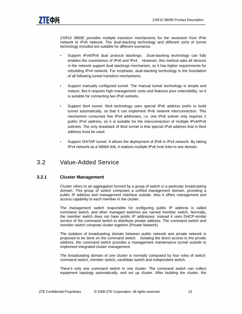
Cluster refers to an aggregation formed by a group of switch in a particular broadcasting domain. This group of switch composes a unified management domain, providing a public IP address and management interface outside. Also it offers management and access capability to each member in the cluster.
The management switch responsible for configuring public IP address is called command switch, and other managed switches are named member switch. Normally, the member switch does not have public IP addresses; instead it uses DHCP-similar service of the command switch to distribute private address. The command switch and member switch compose cluster together (Private Network)
The isolation of broadcasting domain between public network and private network is proposed to be done on the command switch. Isolating the direct access to the private address, the command switch provides a management maintenance tunnel outside to implement integrated cluster management.
The broadcasting domain of one cluster is normally composed by four roles of switch: command switch, member switch, candidate switch and independent switch.
There’s only one command switch in one cluster. The command switch can collect equipment topology automatically, and set up cluster. After building the cluster, the
ZXR10 3900E Product Description
14 © 2009 ZTE Corporation. All rights reserved. ZTE Confidential Proprietary
command switch provides a management tunnel for the cluster to manage the member switch. Before joining in the cluster, the member switch is the candidate switch. And the switch that does not support cluster management is called the independent switch.
The networking topology of the cluster management is as shown in Figure 4
Figure 4 The Networking Topology of Cluster Management
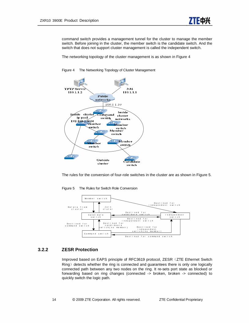
The rules for the conversion of four-role switches in the cluster are as shown in Figure 5.
Figure 5 The Rules for Switch Role Conversion
C o m m a n d s w t i c h
C a n d i d a t e s w i t c h
M e m b e r s w i t c h
I n d e p e n d e n t
s w i t c h
D e s t i n e d f o r c o m m a n d s w i t c h
D e s t i n e d f o r c a n d i d a a t e
s w i t c h ( n o m e m b e r )
D e s t i n e d f o r i n d e p e n d e n t s w i t c h
J o i n c l u t e r
D e l e t e f r o m c l u s t e r
D e s t i n e d f o rc a n d i d a t e s w i t c h
D e s t i n e d f o r i n d e p e n d e n t
s w i t c h ( n o m e m b e r )
D e s t i n e d f o r c o m m a n d s w i t c h
D e s t i n e d f o r i n d e p e n d e n t s w i t c h
3.2.2 ZESR Protection
Improved based on EAPS principle of RFC3619 protocol, ZESR(ZTE Ethernet Switch Ring)detects whether the ring is connected and guarantees there is only one logically connected path between any two nodes on the ring. It re-sets port state as blocked or forwarding based on ring changes (connected -> broken, broken -> connected) to quickly switch the logic path.
ZXR10 3900E Product Description
ZTE Confidential Proprietary © 2009 ZTE Corporation. All rights reserved. 15
ZESR is suitable for multiple rings and multiple domains. Multiple rings are referred to in terms of network topology layers. Each layer is a ring. There are two access points on lower layer access ring to connect with higher layer access ring. The network topology is considered as an individual ring. A ring tangent with it is not a part of it but a part of another. The ring on the higher layer is called the main ring. Others are access rings. Multiple domains indicate there are multiple protecting instances on one ring which are suitable for different service VLAN. They have different logic paths and are independent from each other.
3.2.3 ZTE Ethernet Smart Switch
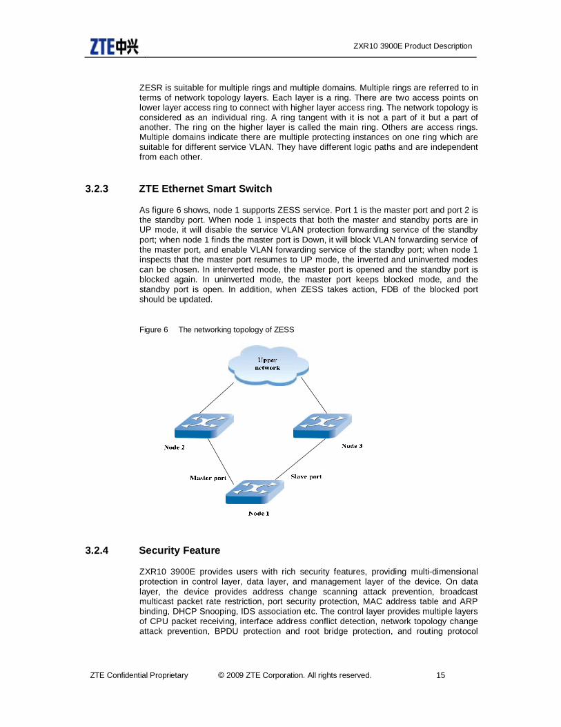
As figure 6 shows, node 1 supports ZESS service. Port 1 is the master port and port 2 is the standby port. When node 1 inspects that both the master and standby ports are in UP mode, it will disable the service VLAN protection forwarding service of the standby port; when node 1 finds the master port is Down, it will block VLAN forwarding service of the master port, and enable VLAN forwarding service of the standby port; when node 1 inspects that the master port resumes to UP mode, the inverted and uninverted modes can be chosen. In interverted mode, the master port is opened and the standby port is blocked again. In uninverted mode, the master port keeps blocked mode, and the standby port is open. In addition, when ZESS takes action, FDB of the blocked port should be updated.
Figure 6 The networking topology of ZESS
3.2.4 Security Feature
ZXR10 3900E provides users with rich security features, providing multi-dimensional protection in control layer, data layer, and management layer of the device. On data layer, the device provides address change scanning attack prevention, broadcast multicast packet rate restriction, port security protection, MAC address table and ARP binding, DHCP Snooping, IDS association etc. The control layer provides multiple layers of CPU packet receiving, interface address conflict detection, network topology change attack prevention, BPDU protection and root bridge protection, and routing protocol

ZXR10 3900E Product Description
16 © 2009 ZTE Corporation. All rights reserved. ZTE Confidential Proprietary
encryption anti-attack protection. Management layer provides hierarchical user management, user password encryption, and SSH.
3.2.5 TR101 Feature
TR101 issued by DSL in April 2006 is suitable for technical demand report of broadband access network. In terms of TR-025 and TR-059 architectures, TR101 proposes a way to enable ATM aggregation network to access Ethernet aggregation network, also it raises an Ethernet-based topology model that meets the requirements of TR-058 operation. And it gives the specific requirements of BRAS devices in access aggregation network, the migration, interconnection, QoS, multicast, security and OAM of all AN nodes.
All mainstream carriers in Europe ask their access and aggregation switches to satisfy TR101. ZTE follows this demand and tries its best to make the product more satisfied to TR101. In doing so, ZTE focuses on:
• Supporting MFF and making sure the isolation of users
For Pvlan, MFF not only realizes L2 isolation, but also makes sure more secure message processing and forwarding as it saves user’s basic information. At the same time, the gateway router controls the communications of all users in the same network segment of L2, which further enhances network security. Centralized management can be realized;
• In addition to give support to DHCP的 option82, it can also inspect the messages that DHCP server returns to customers. And the messages are forwarding as per port accurately, which prevents other people from getting customer’s individual information;
• Supporting IGMP topology discovery. IGMP module when encounters topology change can actively send inspection information to accelerate multicast congestion
• Adding igmp statistical information.
3.2.6 Support External Alarm Input and Output
ZXR10 3900E as shown in Figure 7 totally supports 3-line alarm input and 5-line control output.

ZXR10 3900E Product Description
ZTE Confidential Proprietary © 2009 ZTE Corporation. All rights reserved. 17
Figure 7 Alarm Interface
Blue indicates alarm input and red means control output. As figure 6 shows, if the power supply device connecting to alarm interface of the switch has some problems, the switch will get signal sent by the alarm input mechanism to show level switch, and then the switch will take some actions. For example, it can send warnings to upper monitoring server via network management interface; also it can control and reset the power supply device via control input mechanism.
3.2.7 VCT
VCT (Virtual Cable Test) is a cable fault testing function based on hardware. It uses TDR (Time Domain Reflector) to implement cable diagnosis. It can provide cable error state such as open circuit, short circuit, un-matching impedance, normal cable etc. It can provide cable fault point distance.
ZTE ZXR10 39E series Ethernet switch uses VCT to maintain cable from remote. It can measure faults of short circuit and broken circuit with fault point error within 1 meter. ZXR10 39E series Ethernet switch can automatically get rid of user-side configuration error factors by VCT cable test, so as to further locate the specific device, port and fault cable distance. Most faults can be located and removed at network management center to reduce network maintenance workload, so as to reduce the difficulty and cost of operation and maintenance.
3.2.8 SFP DOM
DOM (Digital Optical Monitoring) is a part of optical module. The optical module supporting DOM service can get temperature, voltage, current and the power consumption in processing traffic. In addition, each optical module is set with some threshold in operation (including alarm threshold and warning threshold). After initiating DOM service, the operating status can be polled via 12C bus of the optical module, and compare the status with the preset threshold. When the value exceeds the threshold, syslog and SNMP trap modes can be used to send warnings.

ZXR10 3900E Product Description
18 © 2009 ZTE Corporation. All rights reserved. ZTE Confidential Proprietary
3.2.9 SFlow
With the increasing development of network services in commercial environment, the existing network becomes bigger and bigger. As there are more and more devices and traffics in the network, the cost in carrying out network maintenance is higher and higher. So how to manage network equipment efficiently and how to implement real-time traffic monitoring and analysis have become more and more important to carriers. Currently, vendors provide multiple network traffic monitoring technologies respectively. But most of these traffic monitoring technologies are private or build based upon hardware. sFlow currently is the standard traffic monitoring technology listed by IETF, it requires simpler hardware, less resource and more universal technology, as a result, it has been implemented by many vendors.
Figure 8 Basic Architecture of SFlow
sFlow services are mainly composed by three parts: sFlow message sampling unit, sFlow proxy unit, and sFlow analyzer. Usually, the sampling and proxy units of sFlow are integrated in network device, and sFlow analyzer is built at the exterior of the system, analyzing multiple sFlow proxy messages in the network. The entire system is basically as shown in figure 8.
sFlow sampling unit is the basic part of sFlow mechanism. It samples messages over the network interface that supports sFlow, and then it will send the messages to sFlow proxy unit for processing. sFlow Collector implements sFlow management, monitoring, collection and analysis. It is responsible for saving and analyzing messages from all sFlow Agent. Then it will give analysis report on traffic and service.
3.2.10 ACL
To filter data, a series of matching rules need to be configured for network device to identify the objects needs filtering. When particular object is identified, corresponding data packets are permitted or prohibited based on the pre-set policy. ACL (Access Control List) can implement all these functions. Adopting packet filtering, ACL reads information in header of packets of L2, L3 and L4 such as source address, destination address, source port, and destination port. It filters packets based on the pre-defined rules and implements access control.

ZXR10 3900E Product Description
ZTE Confidential Proprietary © 2009 ZTE Corporation. All rights reserved. 19
Usually ACL is adopted to implement data packets filtering, policy routing and special traffic control. An ACL contains one or multiple rules for special types of data packets. The rules inform switch whether to permit or reject data packets that match the selecting standards specified in the rules. The data packets matching rules defined by ACL can be imported to other occasions where traffic needs classifying, for example, in QoS to define the traffic classification rules.
The ACL of ZXR10 39E switch falls into four categories: standard ACL, expanded ACL, L2 ACL, and hybrid ACL.
Standard ACL only filters L3 IP source addresses. In practice, most ACLs are filtered based on IP resource addresses. The limitation for standard ACL is that it can only filter source IP address. If the network administrator wants to restrict the access of employees for Internet resource of particular websites or TCP ports, he cannot achieve this by standard ACL. He has to choose other types of ACL.
The expanded ACL filters the header fields of the IP, TCP, UDP, and ICMP protocols. These fields include source IP address, destination IP address, protocol No., ToS, Precedence, DSCP, and Fragment. The fields of the TCP header include source port, destination port and Established. The fields of the UDP header include source port and destination port. The fields of the ICMP header include Type and Code. The expanded ACL meets more complicated requirements and makes smaller traffic classification by filtering the multiple fields in the L3 and L4 packets. Thus this type of ACL can be applied in QoS traffic classification.
L2 ACL mainly filters the fields in the L2 header, including source MAC, destination MAC, Ethernet protocol type, VLAN label and VLAN priority. L2 ACL is mainly used in the access control on the same network segment. When it is not necessary to know the IP address or a protocol rather than the IP is used, some network resources can be protected by filtering the L2 MAC addresses and VLAN labels.
The hybrid ACL is capable of filtering packet headers of L2, L3 and L4. The fields filtered on L2 include VLAN label, source MAC address and destination MAC address. The fields filtered on L3 include source IP address, destination IP address, and IP protocol ID. The fields filtered on L4 include source port and destination port. The hybrid ACL combines the characteristics of the expanded ACL and L2 ACL. The filtering based on the IP address and MAC address bound together can be used to further implement controlled access to the network resources.
3.2.11 QoS
Traditional network provides try-best service which treat all messages equally. Network device based upon the coming sequence tries its best to deliver the message to its destination. However, this method can not guarantee the reliability and latency in the course of transport
Together with the booming development of new implementations, there are new requirements for network service quality, so traditional “Try-Best” service can not fit the implementation. For example, the latency of delivery of services likes VoIP service and real-time video transport may disable customer’s normal implementation. Guaranteed QoS support in network is the most considerate way to solve this problem.
QoS provides different service quality in terms of different implementations, e.g. provide particular bandwidth to reduce packet loss, decrease latency and jitter in delivering messages. As a result, QoS provides the following services:
ZXR10 3900E Product Description
20 © 2009 ZTE Corporation. All rights reserved. ZTE Confidential Proprietary
• Traffic Classification
• Traffic Policing
• Traffic Shaping
• Queue Scheduling and Default 802.1p priority
• Reroute and policy route
• Priority Marking
• Port Mirroring
• Traffic Statistics
3.2.11.1 Traffic Classification
Traffic refers the packets passing by the switch. Traffic classification actually referring to the classification of the packets passing by the switch defines or describes messages with some features.
QoS traffic classification is based upon ACL whose rule must be permit. User can classify packets according to some ACL options, e.g. the source IP message, destination IP address, source MAC address, destination MAC address, IP protocol type, TCP source port number, TCP destination port number, UDP source port number, UDP destination port, ICMP type, ICMP Code, DSCP, ToS, precedence, IN VLAN ID, Out Vlan ID and 802.1p precedence.
3.2.11.2 Traffic Policing
Traffic policing is the restriction to certain traffic to prevent it from exceeding the stated bandwidth. For the exceeding part, the following measures can be carried out:
• Discard or forward
• Change its DSCP value
• Change its discarding precedence (messages with high priority will be discarded firstly)
Traffic policing will not cause extra latency. Its working procedures as shown in Figure 9.

ZXR10 3900E Product Description
ZTE Confidential Proprietary © 2009 ZTE Corporation. All rights reserved. 21
Figure 9 The Working Procedure of Traffic Policing
ZXR10 3900E series implements Single Rate Three Color Marker(RFC2697) and Two Rate Three Color Marker(RFC2698) services. Both algorithms support Color-Blind and Color-Aware modes.
Meter works in two modes: in Color-Blind mode, it supposes the packet is colorless; however in Color-Aware mode, it supposes the packet is colored. On the switch, every packet passing by the switch will be distributed with a color in terms of a certain principle (data packet information). Maker colors these IP packets according to the results Meter gets, and these colors will be marked in DS domain.
In the following, two marking algorithms are introduced.
• SrTCM
This algorithm is used in Diffserv traffic conditioner. SrTCM measures traffics and mark packets as per three traffic parameters, i.e. Committed Information Rate (CIR), Committed Burst Size (CBS) and Excess Burst Size (EBS). These three parameters are called green, yellow and red mark. The packet after passing the ingress policing gets tokens from CBS bucket, if so, the packet is in green. If it can not get tokens from CBS bucket, it will get tokens from EBS bucket, and the packet will be in yellow. If it can not get tokens from EBS bucket, the packet is in red. In default, red packets are discarded.
• TrTCM
This algorithm is used in Diffserv traffic conditioner. trTCM measures IP traffic and colors the packets in green, yellow and red according to two speed rate (Peak Information Rate PIR and Committed Information Rate,CIR ), as well as their CBS and PBS. If the packet number exceeds PIR, it will be colored in red. Otherwise, traffic exceeding CIR will be colored in yellow, and the traffic that does not exceed CIR will be marked in green.

ZXR10 3900E Product Description
22 © 2009 ZTE Corporation. All rights reserved. ZTE Confidential Proprietary
3.2.11.3 Traffic Shaping
The traffic shaping is actually the control of the speed of the output message, which enables the message to go out evenly. Traffic shaping is usually used to match message speed with downstream devices, and avoid congestion and message loss.
The major differences between traffic shaping and traffic policing are: traffic shaping is the buffer of the messages that exceeds speed restriction, which ensures the messages are delivered evenly. However, traffic policing is responsible for discarding the messages whose speed exceeds the speed restriction. Traffic shaping will bring in extra latency, but traffic policing won’t.
3.2.11.4 Queue Scheduling and Default 802.1p Priority
Each physical port of ZXR10 supports 8 output queues (Queue 0~7), called CoS queue. The switch implements ingress output queue processing according to the relevant CoS queue of message 802.1p. When network congestion happens, multiple messages will fight for limited resources. And usually queue scheduling is used to solve this problem.
ZXR10 3900E series supports two queue scheduling modes: SP and WRR. 8 output queues of the port can use different modes.
• Strict Priority(SP)
SP schedules packets of all queues strictly according to the queue priority. First of all, the packets with the highest priority will be sent firstly. And the packets whose priority is a little lower than the first ones won’t be sent until all prepreerence packets gone. Following the same principle, the later messages will be forwarded according to their precedences.
Strict priority mechanism enables the key messages to be processed firstly, which guarantees the service quality of the key services. But, queues with low priorities may never be processed.
• Weighted Round Ring(WRR)
WRR enables every queue to be scheduled. But queues are scheduled at different times, i.e. due to different weights (weights show the resource each queue takes up); messages with high priority have more opportunities to be scheduled than the one with low priority.
802.1 labels consist of data priority. If messages accessing the port do not have 802.1p label, the switch give it a default one.
3.2.11.5 Reroute and Policy Route
Reroute means to make new decisions in terms of traffic classification to the forwarding of messages that have some attributes. So that, the message goes out in other directions, i.e. it is delivered to the appointed port, CPU or next-hop IP address.
Reroute the message to the next-hop IP address can realized policy route.
ZXR10 3900E Product Description
ZTE Confidential Proprietary © 2009 ZTE Corporation. All rights reserved. 23
For message forwarding control, policy-based route is more powerful than traditional route in controlling aspect. It can choose forwarding path according to the matched field in ACL. Policy route can in some way realized traffic engineering, which enables streams with different quality and different services (e.g. voice and FTP) follow different ways. Users now have more and more requirements for network performance, so the selection of packet forwarding path according to services or user classification is very necessary.
3.2.11.6 Priority Marking
Priority marking is to reallocate a set of service parameters to special streams ACL describes. The following processing can be carried out:
• Change CoS queue of data message, and change 802.1p value.
• Change CoS queue of data message, and remain 802.1p value.
• Change DSCP value of data message.
• Change priorities for discarding message
3.2.12 Port Mirroring
Port mirroring can automatically copy the traffic of one port to another, so that the network administrator can real-timely analyze the port traffic for detecting network fault, offering a monitoring means for network management personnel. For the ZXR10 3900E, any port can be configured as a mirror port. Mirroring is also possible between the ports operating at different rates. It is also possible to mirror the traffic of multiple ports to one port, and mirroring can be enabled in multiple mirror groups.
3.2.13 Traffic Statistics
Traffic statistics service is used to calculate service packets, so that real network status can be known for further reasonable network resource distribution. Traffic statistics mainly refers to the number of the packet ingress port receives.
3.2.14 NTP
NTP (Network Time Protocol) is a time synchronous protocol used between different network members. Its transport is based upon UDP. The devices implementing NTP adjust system clocks automatically by exchanging NTP messages. In this way, they keep their clock the same. ZXR10 3900E can be deployed as NTP Client in real network application.
3.2.15 RADIUS
RADIUS ( Remote Authentication Dial In User Service ) is a standard AAA(Authorization, Authentication, Accounting) protocol. For router, AAA can

ZXR10 3900E Product Description
24 © 2009 ZTE Corporation. All rights reserved. ZTE Confidential Proprietary
authenticate users accessing routing switch to prevent illegal users from accessing. At the same time, services like DOT1X also needs to use RADIUS for authentication and accounting.
Currently, ZXR10 3900E supports RADIUS authentication service. It can provide accessed routing switch with Telnet user authentication.
ZXR10 3900E supports multiple RADIUS server groups. Each RADIUS is allowed to configure 3 authentication servers. Each group can set the time for setting server and the time for resetting. The administrator is capable of configuring different RADIUS group to choose specific RADIUS server.
3.2.16 SNMP
The SNMP subsystem implements the SNMP AGENT function, and supports all the protocol operations of the SNMP agent specified in SNMP V1 /V2c/V3.
The protocol operations of SNMPv1 are:
• get-request
• get-next-request
• get-response
• set-request
• trap
• The protocol operations of SNMPv2 are:
• get-request
• get-next-request
• get-bulk-request response
• set-request
• inform-request
• snmpV2-trap
The Management Information Library (MIB) is described by using SMIv1 and SMIv2. The MIB consists of the following parts:
• Management objects supported by the core router
• Management objects of the routing protocol
ZXR10 3900E Product Description
ZTE Confidential Proprietary © 2009 ZTE Corporation. All rights reserved. 25
• Management objects of the network management protocol
• Management objects of the TCP/IP support protocol
• Management objects of the high-speed network interface
• Management objects of important data and configuration parameters
• Management objects compatible with SMIv1
• System configuration parameters
• Other protocol management objects
The related software subsystems are integrated with the related sub-agent functions.
3.2.17 RMON
We can use RMON (Remote Monitoring) to keep an eye on remote services. By using RMON, data collection and processing are done by a remote inspector, i.e. routing switch system. The routing switch at the same time contains a RMON proxy software handling communication by SNMP and network management. Usually, information only goes from routing switch to network management system when special requirements are raised.
3.2.18 DOT1X
The 802.1X is a Client/Server-based access control and authentication protocol. It authenticates the user devices connected to the system ports and determines whether to allow the users to access the services provided by the system through the ports, to prevent unauthorized data transfer between the users and the services provided by the system. The access control of the 802.1X first only allows the EAPOL frames to pass the ports to which the user devices are connected. Other data are not allowed to pass the ports unless the authentication is passed.
With the 802.1X, the access point at which the authenticator system is connected to the LAN has two logical ports: Controlled port and uncontrolled port. Disregard of its authentication status, an uncontrolled port can freely exchange PDUs with other systems. A controlled port can exchange PDUs with other systems only when its status is authenticated. The PAE is an entity that runs and authenticates the related algorithms and protocols. The supplicant PAE responds to the requests from the authenticator PAE, providing the authentication information. The authenticator PAE communicates with the supplicant PAE, and sends the information received from the supplicant PAE to the authentication server, which checks such information to determine whether to allow the supplicant to access its services. The authenticator PAE relies on the authentication result to control the authorized and unauthorized status of the controlled port. The authenticator PAE exchanges protocols with the supplicant PAE via the controlled port and by using the EAPOL protocol, while communicating with the RADIUS server by using the EAPOR.
The 802.1X module performs the following functions:
ZXR10 3900E Product Description
26 © 2009 ZTE Corporation. All rights reserved. ZTE Confidential Proprietary
• Supports the functions available for the authenticator
• Local authentication
• Allows the authenticator PAE to perform protocol exchange via the uncontrolled port and EAPOL
• Supports operation with the uncontrolled port by using the AuthControlledPortControl with the parameters of ForceUnauthorized, Auto, and ForceAuthorized
• Supports operation with the uncontrolled port with parameters of both AdminControlledDirections and OperControlledDirextions
• Supports periodic re-authentication of the supplicant by using a re-authentication timer
• Supports transparent transmission of 802.1x authentication packets when no authentication is enabled
3.2.19 IPTV
As one of the key technologies of ZTE IPTV system architecture, controllable multicast mainly implements at broadband access network side. The device implementing multicast controlling policy (BRAS, DSLAM or switch) is called multicast controlling point, which works as the terminating point of user multicast IGMP request and determines whether to duplicate multicast stream to user port based on corresponding IGMP request and control policy. The multicast controlling point near user saves more network bandwidth. As the key device implementing multicast controlling policy, multicast controlling point supports the following features: IGMP V1/V2, IGMP Snooping, IGMP Filter, IGMP Proxy, IGMP Fast leave, MVR (Multicast VLAN Register), SGR (Static Group Register), UGAC (User Group Access Control), UGAR (User Group Access Record) etc. Multicast on demand authority of user can be controlled by rule and channel binding.
3.2.20 VBAS
VBAS is the short form for Virtual Broadband Access Server. It is a kind of query protocol expanded between IP-DSLAM and BRAS device.
The implementation principle is that L2 point-to-point communication between BRAS and IP-DSLAM. That is to say, port information query and responding packets are directly encapsulated in L2 Ethernet data frame. Configure DSLAM corresponding to VLAN on BAS. Initiate VBAS during PPPoE calling process. That is to say, mapping user band VLAN to corresponding DSLAM. BAS actively initiate user line identity query to DSLAM, which provides BAS with responding user line identity. The local 39E series switch is DSLAM device.
VBAS interaction process and implementation steps are as follows:
ZXR10 3900E Product Description
ZTE Confidential Proprietary © 2009 ZTE Corporation. All rights reserved. 27
User host broadcasting session initiates data packets to request for link establishment and waits for BAS to respond.
One or multiple BAS send service providing data packets to user host if they can provide service when they receive broadcasting.
User host picks out a BAS based on certain principle and sends unicast session to request for data packets.
The selected BAS generates a sole Session ID after it receives requesting of data packets by session. It enters into PPP session phase after is sends acknowledgement data packets to user host.
After it sends acknowledgement data packets, BAS sends BVAS requesting data packets to DSLAM to query which physical port of DSLAM does user host MAC address is from.
DSLAM sends BVAS responding data packets to BAS after it receives VBAS requesting data packets. The corresponding relationship between user host MAC address and DSLAM physical port is returned.
User host holds PPP session with BAS based on Session ID after it receives acknowledge packet of selected BAS. It sends identity authentication requesting packet to BAS by LCP in a point-to-point way.
BAS sends authentication requesting packets to background authentication system of broadband access service provider such as Radius Server. Authentication requesting information contains user account, password, and the physical port it locates at.
Background authentication system (such as Radius Server) returns BAS authentication result responding packet.
BAS returns user host authentication result responding packet.
PPP connection is established if authentication is passed. The two parties can implement PPP data transmission.
ZTE ZXR 10 39E series Ethernet switch VBAS protocol has advantages as follows:
No need for hardware upgrade. Only software upgrade is needed for exiting IP DSLAM and BRAS with the least modifications.
Only port naming is implemented for IP DSLAM. No complicated configuration for BRAS is needed. Light workload.
No need to change the existing networking. Prior investment is protected with continuity.
User and IP DSLAM physical port are bound. Real-time Internet access information of user can be obtained and user port state can be obtained in advance.
3.2.21 ARP
When one network device is sending data to another one, in addition to IP address of the destination equipment, it should also be clear of the MAC address of the destination

ZXR10 3900E Product Description
28 © 2009 ZTE Corporation. All rights reserved. ZTE Confidential Proprietary
equipment. ARP(Address Resolution Protocol)is made to map IP address to MAC address to make sure successful communication. When one device is communicating with an unknown device in the network, the MAC address of the unknown device will be get firstly via ARP. The specific procedures are:
The source equipment broadcasts ARP requests with destination device’s IP address, and all devices in the network will receive this ARP request. If one device realizes that the request is based upon its own IP address, it will then record sender’s ARP information and send ARP response containing its MAC address to source device. In this way, the source device gets the MAC address of the destination device via this ARP response.
In order to reduce ARP packet in the network and accelerate data delivery, IP address and MAC address mapping is cached in the local ARP table. When equipment is going to send data, it will firstly check ARP table according to IP address. If the MAC address of the destination equipment is found in the ARP table, there is no need to send ARP request any more. At the same time, due to the limited space in switch ARP table and the frequent changes of network equipment, the switch should renew ARP table on time (Delete the old items and add in new ones). The dynamic items in ARP table can be deleted automatically, and this course is called ARP aging.
To make the network safer, ZXR10 3900E is able to change the learnt dynamic ARP to static ARP, manual static ARP and eternal ARP table item. Both static ARP and eternal ARP table item do not experience ARP aging. The eternal ARP still exist after reinitiating the switch, however the static ARP will disappear. To prevent from ARP attack, ZXR10 3900E supports ARP protection service, restricting the number of the ARP the switch or other L3 interfaces learn.
3.2.22 DHCP
The DHCP manages the IP address and other related configuration information used on the network, to reduce the complexity in managing the address configuration. When the DHCP service is used on the network, the client and server must be in the same broadcast domain. If a network is built in this way, the ZXR10 3900E must provide the DHCP SERVER function. In another application, the DHCP server and the users are not in the same broadcast domain. The client obtains its address through transit via the ZXR10 3900E. This is what referred to as DHCP relay technically.
The ZXR10 3900E implement the built-in DHCP SERVER function through the DHCP protocol, to enable the dynamic address allocation and management of the DHCP CLIENT, and at the same time provide the user management module on the destination equipment system with the appropriate service management interface for the DHCP CLIENT. They implement transparent interaction between the DHCP CLIENT and DHCP SERVER through the DHCP RELAY AGENT expansion option of the DHCP protocol, to enable the dynamic address allocation and management of the DHCP CLIENT, and at the same time provide the service management module on the destination equipment system with the appropriate service management interface for the DHCP CLIENT.
ZXR10 3900E series support DHCP Client and automatic download of default configuration file via DHCP option field. Without any extra configuration, the device can get IP address, Gateway IP address, and host configuration information, etc. after receiving discovery message, DHCP server will find corresponding preserved IP address as per MAC address, and send other information for example host name, TFTP IP address, Configuration file name to DHCP client via DHCP option at the same time. Then DGCP client will download configuration file from TFTP server via this information,

ZXR10 3900E Product Description
ZTE Confidential Proprietary © 2009 ZTE Corporation. All rights reserved. 29
and then initiate new configuration file with DHCP protocol acting to download configuration file at the same time.
3.2.23 LLDP
LLDP(Link Layer Discovery Protocol)is a new protocol defined in 802.1ab, which enables adjacent devices to send messages to each other, thus updates physical topology information and establishes device management information base. LLDP working process is as follows:
• Sends link and management information of local device to the adjacent device;
• Local device receives network management information from adjacent device;
• Store the network management information of adjacent device in MIB base of local device. Network management software can query L2 connection in MIB base.
LLDP doesn’t work as configuration protocol for remote system, nor signaling control protocol between ports. LLDP can discover inconsistency in configuration of L2 protocol for adjacent devices, but it only reports the problem to the upper level management device without providing mechanism to solve the problem.
To be simple, LLDP is a kind of neighbor discovery protocol. It defines criteria for network devices in Ethernet such as switch, router and wireless LAN access points to enable them to announce their existence to other nodes in the network and to store the discovery information of each adjacent device. For example, the information of device configuration and device identification can be declared by this protocol.
LLDP defines a universal announcement information set, a protocol that transmits the announcement, and a method to store the received announcement information. The device that announces its own information can put multiple announcements in one LLDPDU (Link Layer Discovery Protocol Data Unit) to transmit them. The LLDPDU contains a series of short message unit with variable length, which is called type-length-value (TLV) with the description as follows:
• Type indicates the type of the information needs to be sent
• Length indicates the bytes of the information
• Value indicates the actual information needs to be sent
Each LLDPDU contains four compulsory TLV and one optional TLV:
• Device ID TLV;
• Port ID TLV;
• TTL TLV;
• Optional TLV;

ZXR10 3900E Product Description
30 © 2009 ZTE Corporation. All rights reserved. ZTE Confidential Proprietary
• LLDPDU end TLV。
Device ID and port ID are used to identify the sender.
TTL TLV notifies the receiver of the reservation period of all the information. If no update is received from the sender in this period, all related information will be dropped by the receiver. IEEE has defined a suggested update frequency of one transmission per 30 seconds.
Optional TLV contains basic management TVL set (such as port description TVL), special TLV set organized by IEEE 802.1 and special TLV set organized by IEEE 802.3.
LLDPDU end TLV indicates the end of LLDPDU.
3.2.24 UDLD
UDLD is a L2 logic link detection protocol which can detect logic connection of Ethernet link and verify physical connection. Different from physical connection detection, UDLD detects based on neighbors. L1 devices are transparent to UDLD.
Firstly UDLD needs to establish neighbor relationships. When an Ethernet interface with status of UP launches UDLD, the interface sends neighbor joining Hello message to its adjacent device. The interface launching UDLD of the adjacent device sends back an Echo message. Receiving an Echo message indicates that the device considers the two devices are interconnected. It establishes neighbor relationship with the peer-end and also sends an Echo message. Receiving this Echo message by the peer-end, neighbor relationship on the two devices are both established.
After establishing neighbor relationship, they send Hello messages regularly to check whether the link works well. The device updates the buffered neighbor information stored at local and reset time for neighbor timeout. If no Hello detecting message is received until neighbor aging time, the link is considered as abnormal. Corresponding processing will be taken based on different work mode.
There are two work modes for UDLD: common mode and aggressive mode. In common mode, an interface is Down only when protocols packets are received confirming link single pass. No processing will be taken at the interface if no corresponding packets are received or link single pass cannot be affirmed. In aggressive mode, the interface is Down as long as two-way expedite link cannot be guaranteed. The common place of these two modes is that alarm will be printed as long as normal link status cannot be affirmed.
Generally speaking, UDLD makes interface Down in the following situations:
• In common mode, sends Hello neighbor joining message, and receives Echo message which indicates the neighbor of the peer-end is not itself.
• In aggressive mode, sends Hello neighbor joining message, and receives Echo message which indicates the neighbor of the peer-end is not itself.
• In aggressive mode, receives Hello neighbor joining message, and sends Echo message; but no Echo message from the peer-end is received.

ZXR10 3900E Product Description
ZTE Confidential Proprietary © 2009 ZTE Corporation. All rights reserved. 31
• In aggressive mode, all neighbors at the interface exceed the aging period, and no Hello detection message is received.
When the interface is Down or other accidents occurs that leads to failure of the interface, the device needs to send a flush message to notify the adjacent L2 device to delete the information of it.
Launch UDLD; if the Echo message received indicates that the neighbor of the peer-end is not itself; it’s a false connection of interface. UDLD shut down the interface whatever the mode is as shown in Figure 10 and Figure 11.
Figure 10 False connection of interface
D e v ic e A
P O R T
T X R X
P O R T
T X R X
D e v ic e B
P O R T
T X R XP O R T
T X R X
Figure 11 Interface down
D evice A
PO RT
T X RX
PO RT
T X RX
D evice B
PO RT
T X RXPO RT
T X RX
PO RT
T X RX
PO RT
T X RX
Aging time is the protocol packet sending interval (15 seconds by default) ×3. Shut down the interface if no packet is received within aging time if aggressive mode is configured.

ZXR10 3900E Product Description
32 © 2009 ZTE Corporation. All rights reserved. ZTE Confidential Proprietary
3.2.25 Stacking Service
ZXR10 3900E supports SES stacking service. Stacking is actually a management domain composed by some Ethernet switches interconnecting with each other via stacking port. This management domain consists of an active switch and several standby switches. Usually daisy chain is used as shown in Figure 12:
Figure 12 stacking framework
The switches connect with each other via stacking ports and special protocols are used among devices to control topology discovery, calculation, election and route maintenance.
Stacking benefits users in the following ways:
• Sound management. Stacking can realize unified management of multiple devices. One link and one IP address enable sound management of the entire system. Also it can reduce management costs;
• Superior extensibility. Stacking enables user’s on-demand purchase and smooth extension of network capacity. As a result, in the course of network upgrading, it can give user’s investment maximum protection;
• High redundant backup. High reliability with N+1 backup avoids single-point failure and reduces service breakdown.
Compared with single cassette switch, the system can implement the following characteristic services:
• Distributed management: for management, all devices have one unit. The administrator can manage the device via WEB, telnet, console, and snmp. Different equipment is similar to different slots of chassis.

ZXR10 3900E Product Description
ZTE Confidential Proprietary © 2009 ZTE Corporation. All rights reserved. 33
• Distributed forwarding: message forwarding and search can be done locally. So, when one equipment breaks down, other equipment can still work normally, which makes the system more redundant.
• Distributed link aggregation: support cross-equipment link aggregation, so that link backup and load sharing can be implemented among equipment.
3.2.26 VRRP
By a set of detection and voting mechanisms, the VRRP protocol implements route backup in multiple access to the LAN. The protocols maintain uninterrupted services of the network system for the host equipment connected by backing up the gateway equipment in the LAN, that is, acting as the backup for the next-hop equipment on the route of the host equipment connected. The simple detection and voting mechanism provided by the VRRP can rapidly implement backup and changeover in the event of equipment failure. For ordinary configuration, this is completed in 3~5 seconds, which basically satisfies the interrupt-ability requirements of services. In addition, there is no special requirement for the host equipment connected.
Due to the limitation of the working mechanism of the VRRP, the devices working together in one VRRP group must be in the same LAN. In other words, they should not be distributed in different LANs. This way, in the now common network architectures for VLAN, the devices in one backup group must also be in one VLAN, but in one VLAN there can be multiple VRRP backup groups.
3.2.27 Ethernet OAM
3.2.27.1 802.3ah
IEEE 802.3ah mainly implements link level management, taking monitoring and failure processing of point-to-point Ethernet link in the network. Sometimes “last mile detection” is just about this. Link layer OAM is mainly applied for point-to-point direct link detection.
Figure 13 Relationship of sub-layers of OAM in ISO/IEC OSI reference mode
Figure 13 is the location of OAM in ISO/IEC OSI reference model. Above OAM is LLC logic link control or other MAC client layer. Below OAM is MAC layer or optional MAC control sub-layer. OAM layer is optional. OAM covers the following three functions:
• Remote discovery

ZXR10 3900E Product Description
34 © 2009 ZTE Corporation. All rights reserved. ZTE Confidential Proprietary
• Remote loopback
• Link monitoring
DTE involved in OAM sub-layer supports active/passive mode. When OAM is enabled, DTE that both modes support should choose active or passive.
Remote discovery
OAM provides a mechanism to check whether remote DTE has OAM sub-layers. If discovery unsatisfied, OAM client learns that discovery is unsuccessful; and generates discovery unsuccessful alarm. There may be two reasons for unsuccessful discovery: one is that the peer-end doesn’t start OAM; the other is link connection failure. During the process of remote discovery, label domain of OAMPDU message carries urgent link event (including link failure, urgent failure and emergencies). But the particular failure definition of link failure, urgent failure and emergencies are relevant to their implementation. One way to learn about link failure via remote discovery is by OAMPDU timeout; and the other way is to define some specific urgent link events to let client layer to learn about link failure from OAMPDU.
DTE that configured with active mode launches the discovery process. Once the discovery process is completed, when the counterpart entity connecting to remote OAM is in active mode, active DTE is permitted to send any OAMPDU. DTE that configured with passive mode doesn’t launch discovery process. It provides feedback of discovery process launched by remote DTE.
Remote loopback
OAM provides optional data link layer frame-level loopback mode controlled by remote. OAM remote loopback can be applied for failure location and link performance test. When remote DTE is in OAM remote loopback mode, the statistic data of local and remote DTE can be queried and compared at any moment. Query could be implemented before, during, or after loopback is sent to remote DTE. Besides, OAM sub-layer loopback frame can be analyzed to get additional information concerned link health (to determine frame dropping caused by link failure).
If OAM client has sent loopback control OAMPDU, and when it waits the counterpart DTE to indicate its responding message OAMPDU locating at OAM remote loopback, whether OAM client implements OAM remote loopback command on peer-end device is determined by the following process: a) if local DTE source address is larger than that of the peer-end, enter OAM remote loopback based on peer-end command. b) If local DTE source address is smaller than that of the peer-end, ignore OAM remote loopback command of the peer-end and go on working as if nothing is received.
Link monitoring
OAMPDU。Link monitoring is a feature to make statistics of error symbols or error frames received by physical layer within certain interval. Based on the implementation there is a counter at driver all along making statistics of error frames, error symbols and total frames received. The platform reads the information regularly and takes processing based on these error symbols, error frames and total frames. Corresponding event notice will be generated as per which kind of event occurred is detected.
There are four types of link events:
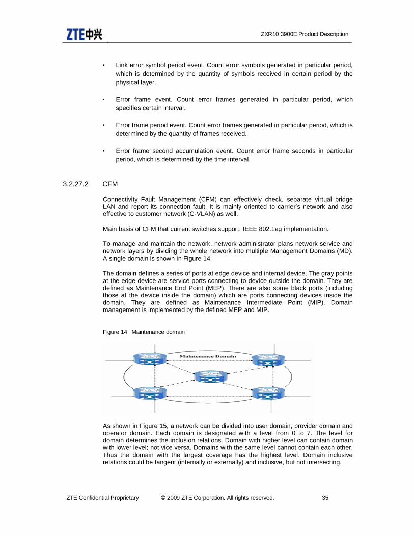
ZXR10 3900E Product Description
ZTE Confidential Proprietary © 2009 ZTE Corporation. All rights reserved. 35
• Link error symbol period event. Count error symbols generated in particular period, which is determined by the quantity of symbols received in certain period by the physical layer.
• Error frame event. Count error frames generated in particular period, which specifies certain interval.
• Error frame period event. Count error frames generated in particular period, which is determined by the quantity of frames received.
• Error frame second accumulation event. Count error frame seconds in particular period, which is determined by the time interval.
3.2.27.2 CFM
Connectivity Fault Management (CFM) can effectively check, separate virtual bridge LAN and report its connection fault. It is mainly oriented to carrier’s network and also effective to customer network (C-VLAN) as well.
Main basis of CFM that current switches support: IEEE 802.1ag implementation.
To manage and maintain the network, network administrator plans network service and network layers by dividing the whole network into multiple Management Domains (MD). A single domain is shown in Figure 14.
The domain defines a series of ports at edge device and internal device. The gray points at the edge device are service ports connecting to device outside the domain. They are defined as Maintenance End Point (MEP). There are also some black ports (including those at the device inside the domain) which are ports connecting devices inside the domain. They are defined as Maintenance Intermediate Point (MIP). Domain management is implemented by the defined MEP and MIP.
Figure 14 Maintenance domain
As shown in Figure 15, a network can be divided into user domain, provider domain and operator domain. Each domain is designated with a level from 0 to 7. The level for domain determines the inclusion relations. Domain with higher level can contain domain with lower level; not vice versa. Domains with the same level cannot contain each other. Thus the domain with the largest coverage has the highest level. Domain inclusive relations could be tangent (internally or externally) and inclusive, but not intersecting.
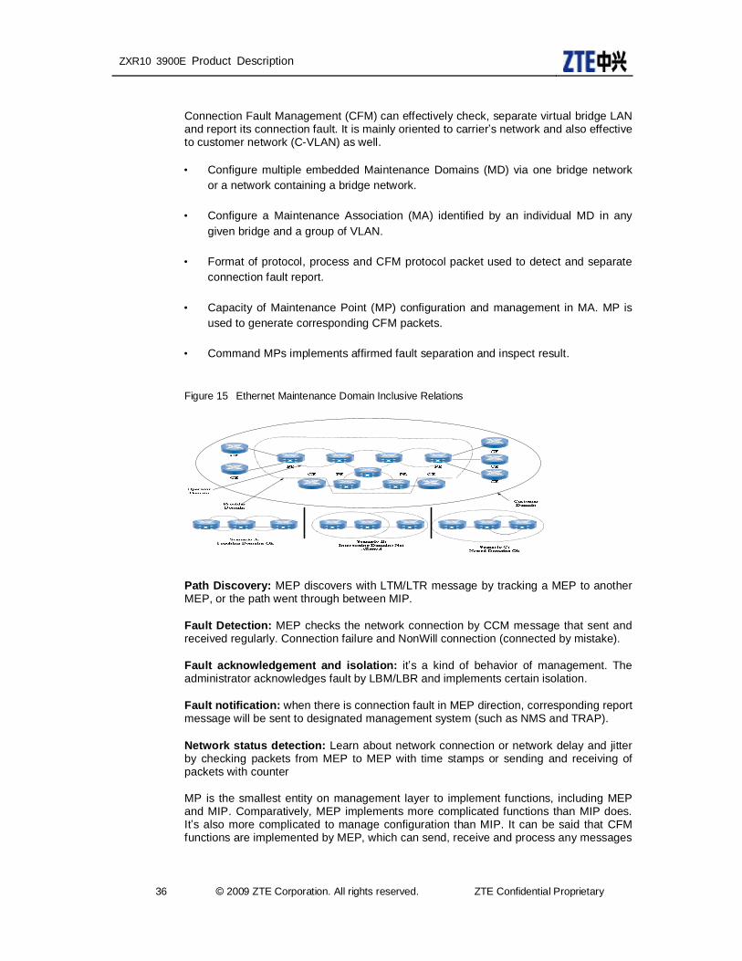
ZXR10 3900E Product Description
36 © 2009 ZTE Corporation. All rights reserved. ZTE Confidential Proprietary
Connection Fault Management (CFM) can effectively check, separate virtual bridge LAN and report its connection fault. It is mainly oriented to carrier’s network and also effective to customer network (C-VLAN) as well.
• Configure multiple embedded Maintenance Domains (MD) via one bridge network or a network containing a bridge network.
• Configure a Maintenance Association (MA) identified by an individual MD in any given bridge and a group of VLAN.
• Format of protocol, process and CFM protocol packet used to detect and separate connection fault report.
• Capacity of Maintenance Point (MP) configuration and management in MA. MP is used to generate corresponding CFM packets.
• Command MPs implements affirmed fault separation and inspect result.
Figure 15 Ethernet Maintenance Domain Inclusive Relations
Path Discovery: MEP discovers with LTM/LTR message by tracking a MEP to another MEP, or the path went through between MIP.
Fault Detection: MEP checks the network connection by CCM message that sent and received regularly. Connection failure and NonWill connection (connected by mistake).
Fault acknowledgement and isolation: it’s a kind of behavior of management. The administrator acknowledges fault by LBM/LBR and implements certain isolation.
Fault notification: when there is connection fault in MEP direction, corresponding report message will be sent to designated management system (such as NMS and TRAP).
Network status detection: Learn about network connection or network delay and jitter by checking packets from MEP to MEP with time stamps or sending and receiving of packets with counter
MP is the smallest entity on management layer to implement functions, including MEP and MIP. Comparatively, MEP implements more complicated functions than MIP does. It’s also more complicated to manage configuration than MIP. It can be said that CFM functions are implemented by MEP, which can send, receive and process any messages
ZXR10 3900E Product Description
ZTE Confidential Proprietary © 2009 ZTE Corporation. All rights reserved. 37
mentioned above. While MIP can only process LTM and LBM message; and send LTR and LBR message as well.
3.2.28 Multi-VRP CE
MVCE provides a kind of function similar to hierarchical PE, which transfer part of PE functions to CE. But MVCE doesn’t need to support MPLS, thus it has low requirements on access and aggregation equipment. The corresponding device should not be called as hierarchical PE. The corresponding device to MVCE is still CE.
User data flows are terminated at CE, which avoids bad impact of broadcast traffic on PE. Complete isolation of different service transmission is implemented at CE, which solves traditional LAN security problem with low cost. User isolation and security guarantee that need to be implemented by PE are currently implemented by CE, which conforms to the development trend of marginalized network security and current requirements of carrier on bearer network.
A comparison between MVCE and hierarchical PE:
• Interfaces between two layers are at least as much as VPN quantity;
• The upper layer PE needs to reconfigure VRF that is already configured on MVCE;
• Run a IGP/BGP counterpart or configure static routing for each VPN;
• Lower layer device doesn’t support MPLS.
MVCE requires the device to support VPN access with IP address overlapping. With the development of technology, MVCE can be implemented on medium-end switch. Configure multiple VRF on MVCE corresponding to multiple VPN sites. Each VFR needs an uplink interface to connect to PE. Configure the same VRF at the corresponding interface on PE.
Since MVCE doesn’t need to support MPLS, there are still ordinary data packets between MVCE and PE instead of MPLS labels. Differently, there is a layer of MPLS labels between hierarchical PE. Thus VPN traffic can only be differentiated by interface on PE, which means PE shall has exactly the same VPN interfaces as much as the VPN MVCE supports.(which is the same as ordinary PE supports L3 VPN configuration.)
A CE with MVCE features actually simulates multiple CE. Each virtual CE is separated from each other and is able to be accessed to multiple VPN users. PE won’t perceive whether it is multiple CE or one MVCE. Thus PE doesn’t need any expansion.
If dynamic routing protocol is run between MVCE and PE, the routing protocol needs to support multiple instances. PE and MVCE exchange routing information via standard EBGP, OSPF, RIP or static route.
Static route and RIP are both standard protocols. But each VRF runs different instances without interference to each other. If static route is configured, it will be ok if it supports VRF.

ZXR10 3900E Product Description
38 © 2009 ZTE Corporation. All rights reserved. ZTE Confidential Proprietary
3.2.29 L2PT
In QinQ VPN mode, if VPN user locates in different places wants to run its own L2 protocol such as STP, LACP and ZDP, the L2 protocol packets needs to be transparently transmitted by core network. However, these packets are usually reserved MAC addresses of bridge. They cannot be directly transparently transmitted. L2PT (layer 2 protocol tunnel) solves this problem. L2PT transparently transmit L2 protocol packets of customer’s network in QinQ VPN network environment.
L2PT networking diagram is shown in Figure 16:
• Edge Switches: locating at edge of carrier’s network to connect customer’s network devices;
• Layer 2 protocol tunnel port: a certain port on Edge Switch, where L2 protocol packet encapsulation and de-encapsulation are implemented;
• Tunneled PDU: encapsulated protocol packets such as ZDP, STP, and LACP.
Figure 16 L2PT networking diagram
At the port where L2PT is not started, L2 protocol packets (STP, ZOP, and LACP) are dropped or transmitted to upper layer to get processed instead of being forwarded. This may cause customer’s network to become several isolated stp domains with regional boundaries. The network in customer’s VPN cannot run an integrated STP topology. L2PT can help users to achieve this by transparently transmitting BPDU packets inside VPN.
Tunneled port on edge switch will encapsulate L2 protocol packets it receives, broadcast the encapsulated packets, and de-encapsulate these packets at the port on remote switch where “tunneled” is started.
Packet encapsulation and de-encapsulation can be implemented by replacing packet MAC address.

ZXR10 3900E Product Description
ZTE Confidential Proprietary © 2009 ZTE Corporation. All rights reserved. 39
4 System Architecture
4.1 Product Appearance ZXR10 3900E is cassette Ethernet switch. Its hardware system is composed of chassis, control switching board, line interface board and power supply module. Its chassis size conforms to European standard.
4.1.1 ZXR10 3900E Appearance
With the chassis height of 1U (1U=44.45mm), ZXR10 3928E/3928E-FI has a dimensional size of 442mm×220mm×43.6mm (W*D*H). ZXR10 3952E chassis high is 2U, it has a dimensional size of 442mm×220mm×88.1mm (W*D*H).ZXR10 3900E adopts dual hot-swappable power supply module, which can be flexibly configured and changed, thus provides higher reliability. All line-out is designed on front including power cable and net cable. It supports 3-port alarm input and 5-port controlling output. M button on the front panel can display the port rate, link status, and duplex status. Expanded slots are suitable for 4GE SFP port, easy to plug and pull. Modular components such as power supply and expanded slots are configured with external push-pull handles for easy push-in and pull-out. At bottom of each slot there is a fastener, which can fasten the slot when slot is installed well to prevent slip.
Figure 17 Appearance of ZXR10 3928E
Figure 18 Appearance of ZXR10 3928E-FI

ZXR10 3900E Product Description
40 © 2009 ZTE Corporation. All rights reserved. ZTE Confidential Proprietary
Figure 19 Appearance of ZXR10 3952E
4.1.2 Hardware architecture
4.1.3 Overall hardware architecture
ZXR10 3900E is cassette product of centralized hardware structure design. All service interfaces are directly connected to switching main control card. Its dual power module provides redundancy and improves reliability.
ZXR10 3900E series products cover two models: ZXR10 3928E and ZXR10 3928E-FI. ZXR10 3928E supports 24 100M electric interfaces and 4 GE SFP expanded slots. ZXR10 3928E-FI supports 24 100M electric optical interfaces and 4 GE SFP expanded slots with no slots or cable ports on the back panel. ZXR10 3952E support fixed 4*GE combo interfaces and 6 line card, each line card support 8*FE electrical or optical interfaces.
ZXR10 3900E provides dual hot-swappable power supply. Net cable and power cable all line out at front. There are two hardware alarm ports on front panel. 3-port alarm input and 5-port controlling output are provided. Input signal can receive external alarm input signals and output signal can control external device. M button provides various display modes of rate and duplex status.
4.1.4 Hardware system working principle
ZXR10 3900E support L2 and complete L3 functions, with level 1 switching for processing and forwarding 100M and 1000M packets. The system hardware working principles are shown in Figure 20.

ZXR10 3900E Product Description
ZTE Confidential Proprietary © 2009 ZTE Corporation. All rights reserved. 41
Figure 20 Hardware Block Diagram for the Hardware of ZXR 10 3900E
4.1.5 Introduction of board modules
ZXR10 3900E system contains one main control card and service expanded slots, which can be divided into switch and control module, power supply module, and interface module.
4.1.5.1 Control module
Control and switch module is the core part of ZXR10 3900E. It mainly implements two functions of control module and switch module.
In ZXR10 3900E system, control and switch module is installed in cassette structure with no independent panel. Its interfaces and signal indicators are on the front panel of the system.its block diagram is shown in Figure 21.

ZXR10 3900E Product Description
42 © 2009 ZTE Corporation. All rights reserved. ZTE Confidential Proprietary
Figure 21 Diagram of main control card
4.1.5.2 Control module
The control module is composed of the main processor and some external application chips. It provides external operation interfaces, for example, serial ports and Ethernet ports, by which the system can process all kinds of applications. The main processor is a high-performance CPU processor, which performs the following functions:
System NM protocol, for example, SNMP
Network protocols, for example, OSPF, RIP, and BGP-4
Providing the operation and management interfaces for line cards
Data operation and maintenance
4.1.5.3 Switch module
The switch module is designed with a dedicated Switch chip, which is integrated with multiple Gigabit and Gigabit bi-directional interfaces, allowing it to process wire-speed switching of multiple ports. The Switch chip provides the following functions:
• Store and forward switching
• Supporting 9KB jumbo frames
• Supporting priority queuing, where frames can be dropped selectively when the CoS queue is in congestion

ZXR10 3900E Product Description
ZTE Confidential Proprietary © 2009 ZTE Corporation. All rights reserved. 43
• Providing one management and control timer for each port
4.1.5.4 Interface module
ZXR10 3900E supports 4-port GE optical interface module, which supports optical-electric self-adaptive interface. All optical interfaces adopt hot-swappable optical module so that one line card supports various transmission media and distance requirements. Thus additional line cards can be reduced and users can obtain the best benefits with the smallest investment.
4.1.5.5 Power Module
ZXR10 3900E supports AC power supply. It adopts hot-swappable cassette power supply module and implements 1+1 hot backup of power supply, which improves the reliability of the power supply system.
4.2 Software Architecture The ZXR10 3900E series products are multi-layer switches with L2 switching and L3 routing capabilities and support for multiple functions, providing L2/3 wire speed switching and routing and QoS assurance. The system software performs management, control, and data forwarding. Its basic operations include system start, configuration management, running of protocols, maintenance of tables, setting switch chips, and status control, as well as software forwarding of some special packets. The system software must implement the following functions:
• Implementing major L2 protocol functions, including 802.1D STP protocol, 802.1P priority control, related functions of 802.1Q VLAN, and 802.3ad link aggregation
• Supporting Ipv4 protocol stacks and basic routing protocols
• Implementing multi-layer services such as ACL and DHCP
• Implementing some broadband access functions
• Implementing network management protocol SNMPv3 and Agent
• Allowing users to perform network management via the serial terminal, Telnet, or SNMP Manager, including network configuration management, fault management, performance management and security management.
• Smooth upgrade of the software version, and on-line upgrade of the active/standby protocol processing cards and switching network cards.
• Network security function
Based on the system functions mentioned above, the system software could be divided into five subsystems.

ZXR10 3900E Product Description
44 © 2009 ZTE Corporation. All rights reserved. ZTE Confidential Proprietary
• Operation support subsystem, including software modules such as BSP, ROS, SSP, and VxWorks kernel
• MUX subsystem, including the data distribution module, statistics and monitoring module, and driving and encapsulation module. The data distribution module distributes data packets to the driver and upper-layer software. The statistics and monitoring module measures data, forwards information, and monitors the software table.
• L2 subsystem, including processing STP protocol, LACP protocol, IGMP SNOOPING protocol, MAC address management, VLAN management and L2 data forwarding
• L3 subsystem, which implements basic protocols of TCP/IP, such as IP, ARP, ICMP, TCP, and UDP, and application protocols such as FTP and Telnet, and implements unicast and multicast routing protocols, performing L3 data forwarding.
• NM and operation & maintenance subsystem, which implements the Agent function of the SNMP network management, supports command line management, provides operation & maintenance interfaces, and provides MIB information.
4.2.1 Operation Support Subsystem
The operation support subsystem drives and encapsulates the bottom-layer hardware, providing support for other software systems on the upper layer. This subsystem provides support for the running of the hardware, allocating resources for the hardware, and provides the hardware-related interfaces for the upper-layer software. The operation support subsystem relies on the RoS platform of the ZXR10, and it is composed of system support, system control, version load control, BSP, and SSP. It can be further divided into the operating system kernel, process scheduling, process communication, timer management, and memory management modules. The functional block diagram for the operation support subsystem is shown in Figure 22.
Figure 22 Functional Block Diagram for the Operation Support Subsystem

ZXR10 3900E Product Description
ZTE Confidential Proprietary © 2009 ZTE Corporation. All rights reserved. 45
4.2.2 MUX Subsystem
The MUX subsystem exchanges information with the driver and the upper-layer software, and measures and monitors the software table of the switch chip. The MUX subsystem mainly performs data distribution and measurement and monitoring. After the MUX layer receives the data packets from the driving module, it forwards the packets by type according to the ETHER TYPES fields in the MAC frames. The data distribution of the MUX also includes the encapsulation of the data sending function of the driver, to provide the modules on the upper layer with a new data sending function for invocation. When the modules on the upper layer have data packets or protocol packets to send, they can invoke the data sending function provided by the MUX. The measurement and monitoring function measures the status of the driver layer, physical layer and MUX layer, measures the packets received/sent, monitors the access to the register, and performs the sniffer operations to the data packets, providing the OAM module with the interface function.
4.2.3 L2 Subsystem
The L2 subsystem performs configuration management (management layer) on the data link layer, protocol processing on L2 (control layer), and data forwarding (data layer or service layer). The function modules are illustrated in Figure 23.
Figure 23 Functional Block Diagram of the L2 Subsystem
4.2.4 L3 Subsystem
By software layer, the L3 subsystem consists of the service control layer and data-forwarding layer. Where, the service control layer is composed of the TCP/IP and IP forwarding support subsystem. The TCP/IP consists of the support protocols and routing protocols. The support protocols are the basic protocols in the Ipv4 protocol suite, providing services to the dynamic routing protocols, while acting as the entities of network management and system monitoring. As the service provider for the upper-layer application entities on the whole router system, support protocols consist of IP, ARP, ICMP, IGMP, TCP, UDP and Telnet protocol entities. Routing protocols are used to generate dynamic routes, and they consist of unicast routing protocols such as RIP, OSPF, and BGP, and multicast routing protocols such as IGMP, PIM-SM, MSDP and MBGP, and they provide related upper-layer protocols such as LDP, VRRP, and RSVP. The IP forwarding and support subsystem is responsible for deletion and modification of the forwarding table and the related strategies, and establishment and maintenance of

ZXR10 3900E Product Description
46 © 2009 ZTE Corporation. All rights reserved. ZTE Confidential Proprietary
indexes, and data interaction between the CPU and switch chip. The IP data forwarding layer inputs, forwards and outputs the data of the strategies, rules and routing tables created by the switch chip according to the IP service control layer.
Figure 24 Functional Block Diagram of the L3 Subsystem
4.2.5 NM and Operation & Maintenance Subsystem
The foreground NM and Operation & Maintenance subsystem uses TCP/IP to implement the agent of the SNMP NM, and meets the management requirements by using the execution entities of the managed entities on the bottom layer. The background NM communicates with the foreground NM via the network to manage the foreground system. In this way, the management network is isolated from the transmission network.
4.3 ZXROS ZXROS is a multitask-based distributed real-time network operating system, providing unified IP protocol supported by all devices from ZTE. ZXROS offers a mature and steady architecture, and has been extensively used by lots of carriers. With reinforcement and extension on the basis of the original platform, the existing platform in terms of user’s service requirements give more consideration on user’s OPEX, CAPEX, service scalability and implementation.
• Sound Encapsulation
− Support multiple operating systems and the smooth upgrade of operating system;
− The configurations of all products are in the same style, which makes user easy to operate and maintain.
• Powerful Monitoring Service

ZXR10 3900E Product Description
ZTE Confidential Proprietary © 2009 ZTE Corporation. All rights reserved. 47
− Monitor processes and memory abnormities.
− Monitor the working status of power supply module, fan, voltage, current, and working temperature.
− Provide fast failure location to guarantee high reliability of the product version.
• Flexible Modular Components
− All service module based upon ZXROS can be added or uninstalled easily; new services can be developed based upon the original architecture.
− Based upon user’s demands, provide flexible on-demand service and fast respond to user’s requirements.
• With superior interoperation, it follows the following standard and protocols
Table 1 L2 Protocol Standard
L2 Protocol Standard IEEE 802.1d Bridging IEEE802.1x Port Based Network Access EEE 802.1s Multiple Spanning Tree IEEE 802.3ad Link Aggregation IEEE 802.1w Rapid Spanning Tree IEEE 802.3ag Service Layer OAM IEEE 802.1Q VLAN tagging IEEE 802.3ah Provider Backbone B 9216 bytes jumbo frame forward on ethernet and pos interface
IEEE 802.1ab LLDP(Link Layer Discovery Protocol)
IEEE 802.1ad VLAN stacking, Select QinQ, VLAN translate
IGMP v1/v2 snooping/proxy
IEEE 802.3 10BaseT IEEE 802.3ae 10Gpbs Ethernet IEEE802.3ah Ethernet OAM IEEE 802.3x Flow Control IEEE 802.3 100BaseT IEEE 802.3z 1000BaseSX/LX IEEE 802.3u 100BaseTx IEEE 802.3ae 10Gbps Ethernet ESRP Ethernet smart Ring Protocol ZESS ZTE Ethernet smart switch IEEE 802.1p VLAN Priority
Table 2 RIP Protocol Standard
RIP Protocol Standard RFC 1058 RIP Version1 RFC 2453 RIP Version2 RFC 2082 RIP-2 MD5 Authentication

ZXR10 3900E Product Description
48 © 2009 ZTE Corporation. All rights reserved. ZTE Confidential Proprietary
Table 3 OSPF Protocol Standard
OSPF Protocol Standard FC 1765 OSPF Database Overflow RFC 2328 OSPF Version 2 FC 2370 Opaque LSA Support RFC 2740 OSPF for IPv6(OSPFv3) RFC 3101 OSPF NSSA Option RFC 3137 OSPF Stub Router
Advertisement RFC 3623 Graceful OSPF Restart–GR helper
Table 4 BGP Protocol Standard
BGP Protocol Standard RFC 1397 BGP Default Route Advertisement
RFC 1772 Application of BGP in the Internet
RFC 1965 Confederations for BGP RFC 1997 BGP Attribute Communities RFC 2385 Protection of BGP Sessions via MD5
RFC 2439 BGP Route-Flap Dampening
RFC 2547bis BGP/MPLS VPNs RFC 2796 BGP Route Reflection draft-ietf-idr-rfc2796bis-02.txt draft-ietf-idr-rfc2858bis-09.txt RFC 2918 Route Refresh Capability for BGP4
RFC 3065 Confederations for BGP
draft-ietf-idr-rfc3065bis-05.txt RFC 3392 Capabilities Advertise-ment with BGP4
RFC 4271 BGP-4 (previously RFC 1771) RFC 4360 BGP Extended Communities Attribute
RFC 4364 BGP/MPLS IP Virtual Private Networks (VPNs)
RFC 2547bis BGP/MPLS VPNs
RFC 4724 Graceful Restart Mechanism for BGP–GR helper
RFC 4760 Multi-protocol Extensions for BGP
RFC 4203 for Shared Risk Link Group (SRLG) sub-TLV
Table 5 ISIS Standard
ISIS Standard RFC 1142 OSI IS-IS Intra-domain Routing Protocol (ISO 10589)
RFC 1195 Use of OSI IS-IS for routing in TCP/IP&dual environments
RFC 2763 Dynamic Hostname Exchange for IS-IS
RFC 2973 IS-IS Mesh Groups
RFC 3373 Three-Way Handshake for Intermediate System to Inter-mediate System (IS-IS) Point-to-Point Adjacencies
RFC 2966 Domain-wide Prefix Distribution with Two-Level IS-IS

ZXR10 3900E Product Description
ZTE Confidential Proprietary © 2009 ZTE Corporation. All rights reserved. 49
ISIS Standard RFC 3567 Intermediate System to Intermediate System(IS-IS)
Cryptographic Authentication
RFC 3719 recommendations for Interoperable Networks using IS-IS
RFC 3784 Intermediate System to Intermediate
System(IS-IS) Extensions for Traffic Engineering (TE)
RFC 3787 Recommendations for Interoperable IP Networks
RFC 3847 Restart Signaling for IS-IS–GR helper
RFC 4205 for Shared Risk Link Group (SRLG) TLV
draft-ietf-isis-igp-p2p-over-lan-05.txt
Table 6 VRRP Standard
VRRP Standard RFC 2787 Definitions of Managed Objects for the Virtual Router Redundancy Protocol
RFC 3768 Virtual Router Redundancy Protocol
Table 7 LDP Standard
LDP Standard RFC 3036 LDP Specification draft-jork-ldp-igp-sync-03 RFC 3037 LDP Applicability RFC 3478 Graceful Restart Mechanism
for LDP–GR helper
Table 8 IPV6 Standard
IPV6 Standard RFC 1981 Path MTU Discovery for IPv6 RFC 2375 IPv6 Multicast Address
Assignments RFC 2460 Internet Protocol Version 6(IPv6) Specification
RFC 2461 Neighbor Discovery for IPv6
RFC 2462 IPv6 Stateless Address Auto configuration
RFC 2463 Internet Control Message Protocol(ICMPv6) for the Internet Protocol Version 6 Specification
RFC 2464 Transmission of IPv6 Packets over Ethernet Networks
RFC 2529 Transmission of IPv6 over IPv4 Domains without Explicit Tunnels
RFC 2545 Use of BGP-4 Multi-protocol Extension for IPv6 Inter-Domain Routing
RFC 2710 Multicast Listener Discovery (MLD) for IPv6
RFC 2740 OSPF for IPv6 RFC 3306 Unicast-Prefix-based IPv6 Multicast Addresses
RFC 3315 Dynamic Host Config-ration Protocol for IPv6
RFC 3587 IPv6 Global Unicast Address Format
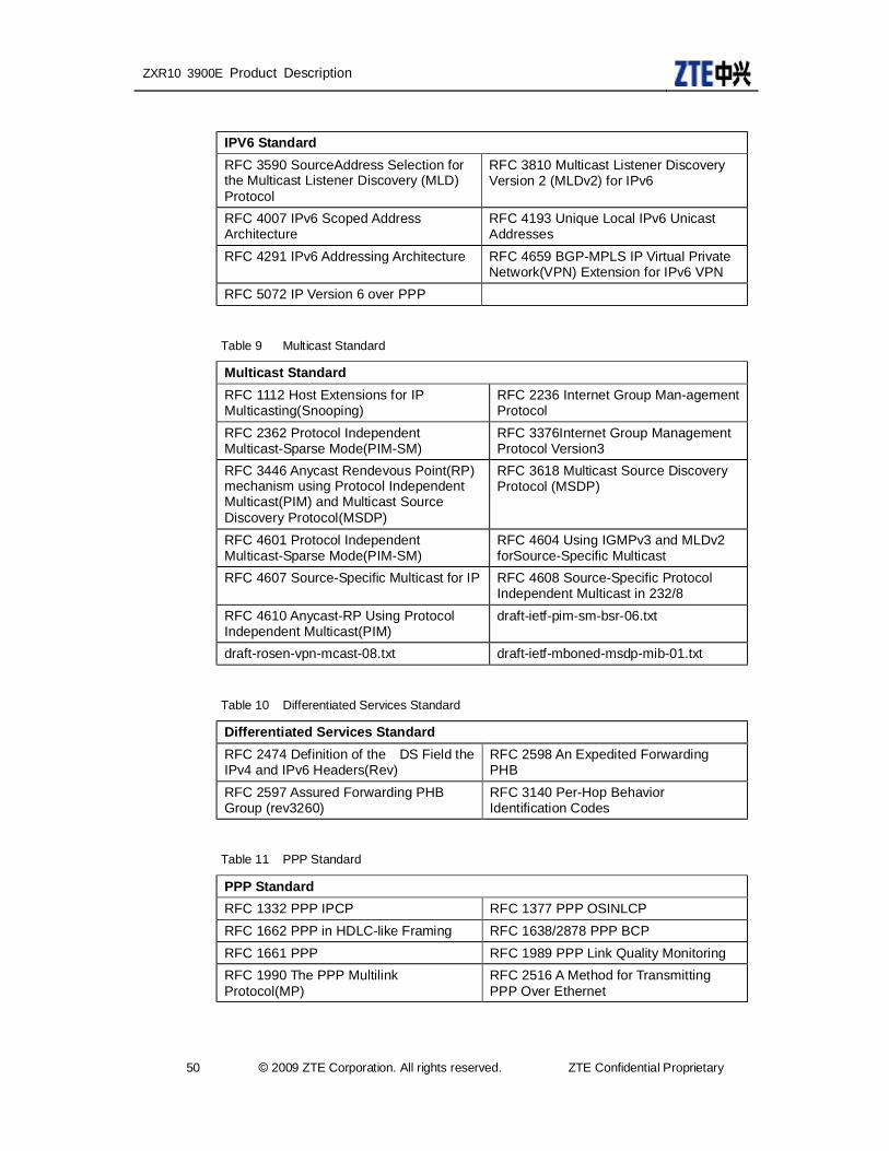
ZXR10 3900E Product Description
50 © 2009 ZTE Corporation. All rights reserved. ZTE Confidential Proprietary
IPV6 Standard RFC 3590 SourceAddress Selection for the Multicast Listener Discovery (MLD) Protocol
RFC 3810 Multicast Listener Discovery Version 2 (MLDv2) for IPv6
RFC 4007 IPv6 Scoped Address Architecture
RFC 4193 Unique Local IPv6 Unicast Addresses
RFC 4291 IPv6 Addressing Architecture RFC 4659 BGP-MPLS IP Virtual Private Network(VPN) Extension for IPv6 VPN
RFC 5072 IP Version 6 over PPP
Table 9 Multicast Standard
Multicast Standard RFC 1112 Host Extensions for IP Multicasting(Snooping)
RFC 2236 Internet Group Man-agement Protocol
RFC 2362 Protocol Independent Multicast-Sparse Mode(PIM-SM)
RFC 3376Internet Group Management Protocol Version3
RFC 3446 Anycast Rendevous Point(RP) mechanism using Protocol Independent Multicast(PIM) and Multicast Source Discovery Protocol(MSDP)
RFC 3618 Multicast Source Discovery Protocol (MSDP)
RFC 4601 Protocol Independent Multicast-Sparse Mode(PIM-SM)
RFC 4604 Using IGMPv3 and MLDv2 forSource-Specific Multicast
RFC 4607 Source-Specific Multicast for IP RFC 4608 Source-Specific Protocol Independent Multicast in 232/8
RFC 4610 Anycast-RP Using Protocol Independent Multicast(PIM)
draft-ietf-pim-sm-bsr-06.txt
draft-rosen-vpn-mcast-08.txt draft-ietf-mboned-msdp-mib-01.txt
Table 10 Differentiated Services Standard
Differentiated Services Standard RFC 2474 Definition of the DS Field the IPv4 and IPv6 Headers(Rev)
RFC 2598 An Expedited Forwarding PHB
RFC 2597 Assured Forwarding PHB Group (rev3260)
RFC 3140 Per-Hop Behavior Identification Codes
Table 11 PPP Standard
PPP Standard RFC 1332 PPP IPCP RFC 1377 PPP OSINLCP RFC 1662 PPP in HDLC-like Framing RFC 1638/2878 PPP BCP RFC 1661 PPP RFC 1989 PPP Link Quality Monitoring RFC 1990 The PPP Multilink Protocol(MP)
RFC 2516 A Method for Transmitting PPP Over Ethernet
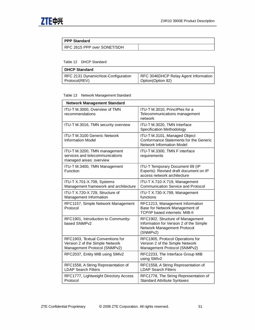
ZXR10 3900E Product Description
ZTE Confidential Proprietary © 2009 ZTE Corporation. All rights reserved. 51
PPP Standard RFC 2615 PPP over SONET/SDH
Table 12 DHCP Standard
DHCP Standard RFC 2131 DynamicHost-Configuration Protocol(REV)
RFC 3046DHCP Relay Agent Information Option(Option 82)
Table 13 Network Management Standard
Network Management Standard ITU-T M.3000, Overview of TMN recommendations
ITU-T M.3010, PrincIPles for a Telecommunications management network
ITU-T M.3016, TMN security overview ITU-T M.3020, TMN Interface Specification Methodology
ITU-T M.3100 Generic Network Information Model
ITU-T M.3101, Managed Object Conformance Statements for the Generic Network Information Model
ITU-T M.3200, TMN management services and telecommunications managed areas: overview
ITU-T M.3300, TMN F interface requirements
ITU-T M.3400, TMN Management Function
ITU-T Temporary Document 69 (IP Experts): Revised draft document on IP access network architecture
ITU-T X.701-X.709, Systems Management framework and architecture
ITU-T X.710-X.719, Management Communication Service and Protocol
ITU-T X.720-X.729, Structure of Management Information
ITU-T X.730-X.799, Management functions
RFC1157, Simple Network Management Protocol
RFC1213, Management Information Base for Network Management of TCP/IP based internets: MIB-II
RFC1901, Introduction to Community-based SNMPv2
RFC1902, Structure of Management Information for Version 2 of the Simple Network Management Protocol (SNMPv2)
RFC1903, Textual Conventions for Version 2 of the Simple Network Management Protocol (SNMPv2)
RFC1905, Protocol Operations for Version 2 of the Simple Network Management Protocol (SNMPv2)
RFC2037, Entity MIB using SMIv2 RFC2233, The Interface Group MIB using SMIv2
RFC1558, A String Representation of LDAP Search Filters
RFC1558, A String Representation of LDAP Search Filters
RFC1777, Lightweight Directory Access Protocol
RFC1778, The String Representation of Standard Attribute Syntaxes

ZXR10 3900E Product Description
52 © 2009 ZTE Corporation. All rights reserved. ZTE Confidential Proprietary
Network Management Standard RFC1959, An LDAP URL Format RFC2251, Lightweight Directory Access
Protocol (v3) RFC1493, Definitions of Managed Objects for Bridges
GB901, A Service management Business Process Model
GB910,Telecom Operations Map GB909,Generic Requirements for Telecommunications Management Building Blocks
RFC1757, Remote Network Monitoring Management Information Base
GB908,Network Management Detailed Operations Map
RFC1757, Remote Network Monitoring Management Information Base
GB914,System Integration Map
GB917, SLA Management Handbook V1.5
NMF038, Bandwidth Management Ensemble V1.0
TMF508, Connection and Service Management Information Model Business Agreement
TMF801, Plug and Play Service Fulfillment Phase 2 Validation Specification V1.0
TMF605, Connection and Service Management Information Model
NMF037, Sub-System Alarm Surveillance Ensemble V1.0
TMF053, NGOSS Architecture Technology Neutral Specification V1.5
TMF053A, NGOSS Architecture Technology Neutral Specification V1.5
TMF053B, NGOSS Architecture Technology Neutral Specification V1.5
TMF821, IP VPN Management Interface Implementation Specification V1.5
TMF816, B2B Managed Service for DSL Interface Implementation Specification V1.5
Interworking Between CORBA and TMN System Specification V1.0
YD/T 852-1996 General design principle of TMN
YD/T 871-1996 General information model of TMN
YD/T XXXX-2001 General technical specification of broadband MAN
YD/T XXXX-2001 IP Network technical specification-network performance parameter and availability
YD/T XXXX-2000 IP体 Network technical specification –network in general
YDN 075-1998 China public multimedia connunicaitons network management specification
YDN 075-1998 China public multimedia communications network management standard
RFC 1215 A Convention for Defin-ing Traps for use with the SNMP
RFC 1657 BGP4-MIB RFC 1724 RIPv2-MIB RFC 1850 OSPF-MIB RFC 1907 SNMPv2-MIB RFC 2096 IP-FORWARD-MIB RFC 2011 IP-MIB RFC 2012 TCP-MIB RFC 2013 UDP-MIB RFC 2138 RADIUS RFC 2206 RSVP-MIB RFC 2452 IPv6 Management Information Base for theTransmission Control Protocol
RFC 2454 IPv6 Management Information Base for the User Datagram Protocol
RFC 2987 VRRP-MIB RFC 3014 NOTIFICATION-LOGMIB
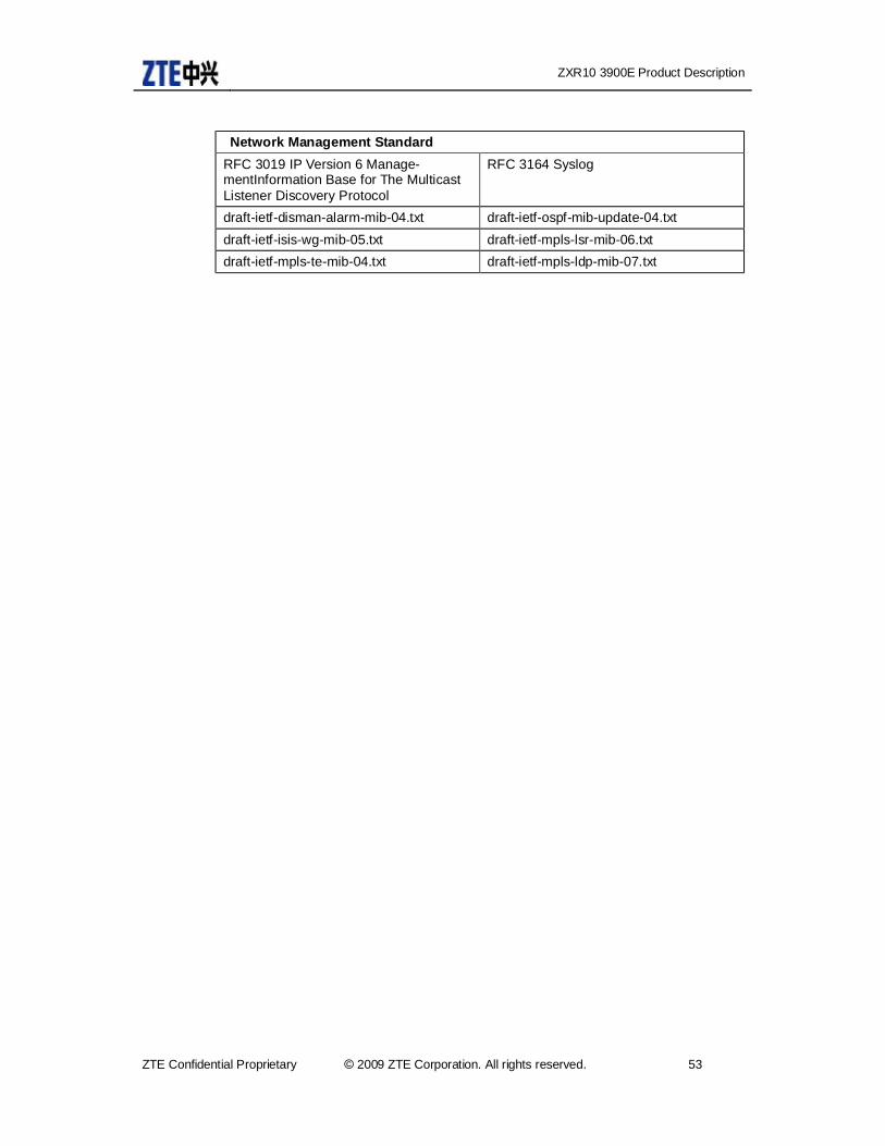
ZXR10 3900E Product Description
ZTE Confidential Proprietary © 2009 ZTE Corporation. All rights reserved. 53
Network Management Standard RFC 3019 IP Version 6 Manage-mentInformation Base for The Multicast Listener Discovery Protocol
RFC 3164 Syslog
draft-ietf-disman-alarm-mib-04.txt draft-ietf-ospf-mib-update-04.txt draft-ietf-isis-wg-mib-05.txt draft-ietf-mpls-lsr-mib-06.txt draft-ietf-mpls-te-mib-04.txt draft-ietf-mpls-ldp-mib-07.txt

ZXR10 3900E Product Description
54 © 2009 ZTE Corporation. All rights reserved. ZTE Confidential Proprietary
5 Technical Parameters and Specifications
Table 14 Physical Parameters
Physical Parameters 3952E 3928E/3928E-FI Size(H×W×D) 88.1mm*442mm×220mm 43.6mm×442mm×
220mm
Weight(Full Configuration, including two power supply modules and subcards)
<20kg <4.5kg
Power Consumption <130W < 30W Working Temperature -5℃~45℃
Storage Temperature -40℃~70℃
Anti-Seismic Design Anti-8 magnitude earthquake design Reliability MTBF:>100,000 hours,MTTR:<30 minutes
5.1 Basic Performance Indices
Table 15 Basic Performance Indices
Basic Performance Indices 3928E/3928E-FI/3952E Switching Capacity 18.8G VLAN 4K MSTP Entity Number 16 Trunk Number 32groups,8 ports per group
ACL 2K QOS Queue 8queues per port Granularity of Port Speed Limitation 64k Multicast Group Number L2 1k/L3 256
Unicast Group Number Subnet route:8K Host route:4K
Dot1x User 2k
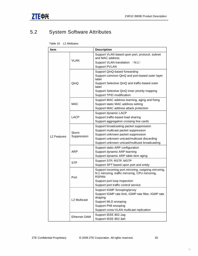
ZXR10 3900E Product Description
ZTE Confidential Proprietary © 2009 ZTE Corporation. All rights reserved. 55
5.2 System Software Attributes
Table 16 L2 Attributes
Item Description
VLAN
Support VLAN based upon port, protocol, subnet and MAC address Support VLAN translation (N:1) Support PVLAN
QinQ
Support QinQ-based forwarding Support common QinQ and port-based outer layer label Support Selective QinQ and traffic-based outer label Support Selective QinQ inner priority mapping Support TPID modification
MAC Support MAC address learning, aging and fixing Support static MAC address setting Support MAC address attack protection
LACP Support dynamic LACP Support traffic-based load sharing Support aggregation crossing line cards
Storm Suppression
Support broadcasting packet suppression Support multicast packet suppression Support unknown packet suppression Support unknown unicast/multicast discarding Support unknown unicast/multicast broadcasting
ARP Support static ARP configuration Support dynamic ARP learning Support dynamic ARP table item aging
STP Support STP, RSTP, MSTP Support SPT based upon port and entity
Port
Support incoming port mirroring, outgoing mirroring, N:1 mirroring, traffic mirroring, CPU mirroring, RSPAN Support port loop inspection Support port traffic control service
L2 Multicast
Support IGMP Snooping/proxy Support IGMP rate limit, IGMP rate filter, IGMP rate shaping Support MLD snooping Support PIM snooping Support cross-VLAN multicast replication
L2 Features
Ethernet OAM Support IEEE 802.1ag Support IEEE 802.3ah

ZXR10 3900E Product Description
56 © 2009 ZTE Corporation. All rights reserved. ZTE Confidential Proprietary
Table 17 L3 Attributes
Item Description
Support IPv4 unicast static route Support RIPv1/v2, OSPFv2, IS-IS, BGP-4 Support policy route Support MVRF Support URPF Support ECMP
IPv6 unicast route
Support IPv6 static route Support RIPng, OSPFv3, IS-ISv6, BGP4+ Support 6to4 tunnel and 6in4 tunnel Support ISTAP
L3 Features
L3 Multicast
Support static multicast Support IGMPv1/v2/v3 Support PIM-SM, PIM-SSM, PIM-DM, MSDP, MBGP
Table 18 QoS
Item Description
Traffic Classification
Support traffic classification based upon physical port Support traffic classification based upon physical port and ACL
Message Remaking
Support the remarking of 802.1p priority, IP Precedence, IP DSCP, IP TOS, Support dual-layer label mapping
Traffic Policing
Support ingress CAR Support traffic-baesd CAR Support ingress/egress traffic policing Support remarking after traffic policing
Congestion Control
Support traffic-based bandwidth control Support RED and WRED Support CAC
Queue Scheduling
Support 8 precedence queues at least. Each queue support minimum/maximum bandwidth management Support WRR, SP and WFQ scheduling
Traffic Shaping
Support egress port shaping Support egress queue shaping
Traffic Classification Support ACL-based traffic classification
Traffic Shaping
Support traffic classification based upon the queue of each layer
QoS Features
Queue Shaping Support SP, WRR

ZXR10 3900E Product Description
ZTE Confidential Proprietary © 2009 ZTE Corporation. All rights reserved. 57
Table 19 Service Management
Item Description
Service Management
Support IEEE 802.1X Support AAA authentication Support DHCP Server, DHCP Relay, DHCP Snooping Support DHCP OPTION 82
Table 20 Reliability
Item Description
Reliability
Support non-stop upgrade Support VBRP protocol, support multiple backups configuration, support backup priority setting, support VRRP switching authentication, support priority replacement mode Support ZESR(ESRP+) Ethernet ring protection Support ZESS dual-homing protection Support ECMP
Table 21 Security
Item Description
Attack prevention
Support anti-DOS attack service Support anti-BPDU attack service Support CPU protection Support anti-ARP attack service MAC addresses flood protection. Restrict port MAC address number Support IPv4 uRPF Support hierarchical command protection Support abnormal message and wrong message protection Support anti-IP fragment Support anti-LAND attack service Support anti-SMURF attack service Support SYN FLOOD attack service Support anti-PING FLOOD attack service Support anti-Teardrop attack service Support anti-Ping of Death attack Support anti-fake IP address attack
Security Features
CPU security protection
Support the initation and disablement of protocol priority processing Support protocol packet protection service Support the filtering the messages going up to CPU

ZXR10 3900E Product Description
58 © 2009 ZTE Corporation. All rights reserved. ZTE Confidential Proprietary
Item Description
Senior security features
Support data log monitoring Support broadcasting suppression Support control/signaling MD5 encryption and certification
Table 22 Operation and Maintenance
Item Description
Operation and maintenance
Support command line service Support hierarchical management authorities Support password aging and confirmation Support console management Support user access service management Support remote access in SSH, TELNET, WEB, SNMP, and SSL modes Support warnings in multiple ways(audio, light alarming platform) Support ZXNM01 unified network platform Support CLI hierarchical network management Support user access control service Support recovery of configuration storage Support operation log record Support alarm log management Support basic MIB service Support traffic statistical service
Cluster management ZGMP, LLDP/ZTP/ZGMP
Operation and Maintenance Service
OAM Support Ethernet OAM Support OAM tool (MAC Ping, MAC trace route, etc.)

ZXR10 3900E Product Description
ZTE Confidential Proprietary © 2009 ZTE Corporation. All rights reserved. 59
6 Analysis of Product TCO
6.1 Analysis of CAPEX • Intelligent QoS prevents transmission congestion and reduces device upgrading
frequency.
Owing to limited memory resource, the traditional processing drops all packets when queue reaches the specified maximum length. TCP timeout may occur which may lead to TCP slow start and congestion avoidance mechanism if large quantity of TCP packets are dropped. When queues drop packets of multiple TCP connections at the same time, multiple TCP connections will have slow start and congestion avoidance, which is called global synchronization. In this way packets sent to queues by multiple TCP connections are reduced at the same time and smaller than the line rate. Thus line bandwidth utilization is reduced. In addition, traffic sent to queues is changing from huge to tiny irregularly, which makes the traffic always fluctuating between low to saturation.
To avoid this, RED (Random Early Detection) packet dropping policy could be adopted. User can set a queue threshold. When queue length is smaller than the low threshold, no packet is dropped. When queue length is between low and high threshold, RED begins to drop packets at random (dropping possibility is higher when queue length is larger). When queue length is larger than high threshold, all packets are dropped.
Since RED drop packets at random, multiple TCP connections transmission rate will not be reduced at the same time. Thus TCP global synchronization can be avoided. When packets of certain TCP connection are dropped, and transmission rate is reduced, other TCP connections are still transmitted at high rate. In this way there are always some TCP connections are transmitted at high rate at any moment so that line bandwidth utilization is improved.
• Dimensional size conforming to European standards, depth less than 220mm, compact structure saves space cost
Corridor or campus switches are usually deployed at places nearby users, which brings about the cost of storage rent. It’s obvious that the lower the cost is, the better it will be. The rent depends on the space occupied. Thus the ultimate result is requirements of device size. The dimensional size for ZXR10 3900E completely conforms to European standards.
• Reducing equipment consumption and implementing green environment protection
ZXR10 3900E adopts no fan silent design. With the advantages of small size, low weight, and large capacity, ZXR10 3900E can help carriers to effectively save resource and lower the requirements of environment.

ZXR10 3900E Product Description
60 © 2009 ZTE Corporation. All rights reserved. ZTE Confidential Proprietary
6.2 Analysis of OPEX • Modular dual power supply
Modular power supply can be flexibly configured and changed. Dual power supply provides higher reliability for carrier-class equipment.
• All cable line out from front panel
For better operation and maintenance, Net cable, power cable and power switch are all on the front panel, which provide great convenience to after-sale maintenance people. They can implement everything with cabinet open. In this way work efficiency is improved.
• M button
On most existing switches, LED indicator of network interface on the panel can only indicate two statuses of rate and link (active). Other information can be obtained only via command line or network management. But in practice there is a status most usually used: duplex status of port, which cannot be obtained in a direct way. M button solves this problem by providing an option to switch the display.
There is no change for indicators in hardware except M button and two status indicators are added. M button status indicator indicates whether the speed indicator on panel port indicates speed or duplex status. The existing two LED indicators are applied for each port. Among them link (active) indicator remains the same by indicating link (active) status. The original speed indicator is used to indicate rate duplex status. Which kind of status it indicates is decided by M button indicator. Only one M button indicator is light up at one time. Switching is controlled by M button by implementing switching upon pressing.
• Expanded slot for power supply is easy to install and disassemble
The modular components such as expanded slot for power supply are configured with external push-pull handle for easy push-in and pull-out. There is a fastener at the bottom of each slot. The fastener will fasten the slot when it is installed to prevent slip.
• Training
ZTE MAN network service platform is equipped with a complete set of consistent powerful network element management system (EMS). Network Management System (NMS) can quickly deploy new equipment and service to reduce training time and reduce cost.
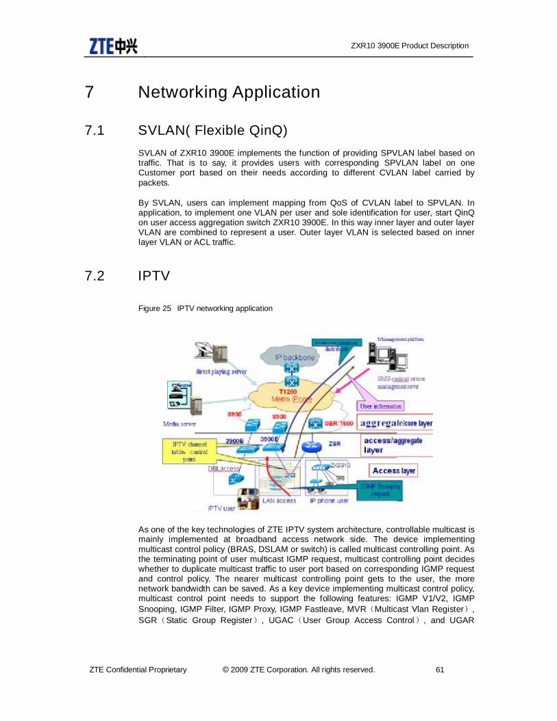
ZXR10 3900E Product Description
ZTE Confidential Proprietary © 2009 ZTE Corporation. All rights reserved. 61
7 Networking Application
7.1 SVLAN( Flexible QinQ) SVLAN of ZXR10 3900E implements the function of providing SPVLAN label based on traffic. That is to say, it provides users with corresponding SPVLAN label on one Customer port based on their needs according to different CVLAN label carried by packets.
By SVLAN, users can implement mapping from QoS of CVLAN label to SPVLAN. In application, to implement one VLAN per user and sole identification for user, start QinQ on user access aggregation switch ZXR10 3900E. In this way inner layer and outer layer VLAN are combined to represent a user. Outer layer VLAN is selected based on inner layer VLAN or ACL traffic.
7.2 IPTV
Figure 25 IPTV networking application
As one of the key technologies of ZTE IPTV system architecture, controllable multicast is mainly implemented at broadband access network side. The device implementing multicast control policy (BRAS, DSLAM or switch) is called multicast controlling point. As the terminating point of user multicast IGMP request, multicast controlling point decides whether to duplicate multicast traffic to user port based on corresponding IGMP request and control policy. The nearer multicast controlling point gets to the user, the more network bandwidth can be saved. As a key device implementing multicast control policy, multicast control point needs to support the following features: IGMP V1/V2, IGMP Snooping, IGMP Filter, IGMP Proxy, IGMP Fastleave, MVR(Multicast Vlan Register), SGR(Static Group Register), UGAC(User Group Access Control), and UGAR

ZXR10 3900E Product Description
62 © 2009 ZTE Corporation. All rights reserved. ZTE Confidential Proprietary
(User Group Access Record). User demanding authorities are controlled by rules and channel binding.
As shown in Figure 25, multicast controlling point is configured on aggregation device ZXR10 3900E. It can establish multicast forwarding table items based on IGMP packets to implement user access control configuration so as to implement preview, play control of the channel and to implement IPTV demands of the users.
7.3 ZESR
Figure 26 ZESR networking application
Based on EAPS principle of RFC3619 protocol, ZESR(ZTE Ethernet Switch Ring)is further improved. It checks whether the loop is connected to make sure that there is only one logically connected path between any two points on the ring. It re-set port status (block or forward) based on loop changes (connected-blocked; blocked-connected) to make logic path switch quickly.
In Figure 26, to enhance the network reliability, ZESR is deployed in the middle of access/aggregation layer. When a device on the ring fails, forwarding will not be impacted. The secondary port will be unblocked to implement reverse data forwarding. At the same time MAC table item is notified to get updated to guarantee non-interrupted services.
7.4 ZESS Protecting the uplink links of access/aggregation layer device is a problem that users keep focusing on. Traditional technologies can only implement dual uplink links protection of a single device with single point error on uplinking device. To meet the practical networking needs, ZTE develops more advanced ZESS.

ZXR10 3900E Product Description
ZTE Confidential Proprietary © 2009 ZTE Corporation. All rights reserved. 63
The application of ZXR10 3900E in ZESS is shown in Figure 27:
Figure 27 ZESS networking application
ZXR10 3900E supports ZESS uplink link protection. It can implement single device dual uplink networking such as ZESS domain4 and ZESS domain5. It can implement square connection of two devices and the upper layer NPE such as ZESS domain1. It can also implement crossing connection of two devices and upper layer NPE such as ZESS domain2 and ZESS domain3.
ZXR10 3900E ZESS supports main/standby and load sharingmode. In main/standby mode, the standby link doesn’t carry traiif in normal situation. In load balancing mode, two uplink links can carry part of traffic respectively so as to implement load balancing.

ZXR10 3900E Product Description
64 © 2009 ZTE Corporation. All rights reserved. ZTE Confidential Proprietary
8 Integrated Network Application
8.1 MAN Access Layer Solution ZXR10 3900E series intelligent switches are suitable for the access layer of MAN. For specific, they can be used as community switch, providing users with rich bandwidth and management features in the access layer. The main features are;
• Support flexible SVLAN and realize service separation
• Support port service isolation: PVLAN, etc.
• Support fast service recovery: support ZESR, UDLD and ZESS
• Support MonitorLink service, which enables higher network reliability
• Support L2 multicast
Figure 28 MAN application
8.2 Enterprise Network Solution They are mainly used as L3 switches in enterprise networks. The rich features are:
• Meet the security requirements of enterprise network. Provide powerful security guarantee to network customers via ZSA, security linkage and ACL.

ZXR10 3900E Product Description
ZTE Confidential Proprietary © 2009 ZTE Corporation. All rights reserved. 65
• Enable different authorities to access different services of different enterprises and departments. Provide virtual network by MCE to enable unified IP implementation
• Support stacking service
Figure 29 Enterprise network application
ZXR10 3900E Product Description
66 © 2009 ZTE Corporation. All rights reserved. ZTE Confidential Proprietary
9 Operation and Maintenance
9.1 NetNumen N31 Unified Network Management Platform Due to the development of IP network, there are more and more services implemented by IP network. At the same time, the network ranges larger, and configures harder, plus user’s higher expectation, the network management becomes more and more difficult. Only manual management and passive inspection can not meet the requirements of running the entire system.
Now the maintenance engineer is focusing on how to deploy service swiftly, how to keep steady network operation, how to predict the operating quality of the network and how to locate the failure as soon as it happens. Therefore, the active network monitoring, automatically network failure inspection and recovery, and sound network operation are urgently required to guarantee maximum network profit.
ZTE giving positive response to the call of the times develops NetNumen N31 unified network management system. It is an integrated network management system composed by router, switch and CE, responsible for network element management, network management and service management. It supports multiple sorts of database, has graphic interface in different languages for convenient operation. Besides, this system also provides flexible northbound interface, supporting powerful interconnecting integration.
9.1.1 Network Management Networking Mode
Between NetNumen N31 NMS and ZXR10 3900E series equipment, inband management and outband management networking modes can be used
Inband Management
Inband Management, i.e. instead of requiring an extra DCN, network management information and service data are delivered in the same channel. NetNumen N31 only has to connect with its nearby network equipments, and then together with configured SNMP, it can arrange management.
The advantage of inband management is that flexible networking does not ask for extra investment. But the network management information takes up service bandwidth, so it may seriously affect service quality.
Outband Management
Outband management, i.e. the network management information is delivered in service data independent from service data, so extra DCN is needed. NetNumen N31 network management system is connected with the outband management interface of ZXR10 3900E, so that network management information and service information can be delivered independently.
ZXR10 3900E Product Description
ZTE Confidential Proprietary © 2009 ZTE Corporation. All rights reserved. 67
By using outband management; the breakup of the service channel will not prevent the network management station to do equipment management, so that the transport of network information becomes more reliable. But the independent network is limited by the geographic reasons and requires extra investment.
9.1.2 NetNumen N31 Network Management System
NetNumen N31 network management system is an integrated management system designed by ZTE for its router, switch and CE. It covers network element management, network management and service management. NetNumen N31 network management system provides the following services
• Failure management makes sure steady network operation.
In the maintenance of network management, the administrator urgently needs to know the network operating status to make sure steady network operation. The failure management of NetNumen N31 is responsible for receiving real-time equipment warning and network events from all NE, so that it can give audible and visible information to maintenance staffs; after being comfirmed by maintenance staffs, the collected warning report will be saved for future statistics and search. Failure management is the most important and commly used method in user’s network operating maintenance. Via failure management, user can arrange information search, real-time monitoring, failure filtering, failure location, failure confirmation, failure deletion, and failure analysis for ZXR103900E series device. Besides, NetNumen N31 system also provides voice prompt, graphic warning display, and informs user the failure by sending Email and messages via warning system, Email system, SMS system, which simplifies user’s daily maintenance.
• Performance management enables complete understanding of network services
The traffic direction, traffic load and network load are the key issues in network management. The performance management module of NetNumen N31 is mainly responsible for the performance monitoring and analysis of data entwork and its equipments. The performance data collected by network element will generate performance report after a certain processing, so that maintenance and management departments can get information to guide network engineering, plan, network scheduling and improve network operating quality. Via performance management, user can implement load, traffic direction and interface load collection, get timely service quality report and give prompt evaluations and adjustment on entire network resource configuration.
• Resource management makes reasonable use of network resource
The resource management realizes the management of physical resource and logical resource, so it is an inevitable basic system in carrier’s service progress. Also it is the critical precondition for realizing automatic service intiation and automatic service guarantee. Via resource management, user via the resource management sytem not only can get information of the management of the equipment, module, interface and link in the network, but also can know the operating status of the logical resources, such as, VLAN resource, L2/L3 VPN resource, and MAC addresses
• View management makes network operation clear and easy
ZXR10 3900E Product Description
68 © 2009 ZTE Corporation. All rights reserved. ZTE Confidential Proprietary
View management provides unified network topology and multi-view management, which enables the user to be aware of the network topology and equipment operating running status in the entire network. At the same time, it provides maintenance interfaces for network and equipment. User utilizes view management to know the operating status and warning status of the equipment. And also, it supports fast navigation to other management systems.
• Configuration management enables fast service deployment
The configuration management implements the configuration of ZXR10 3900E series, including equipment management, interface management, VLAN management, L2 attribute management, MPLS management, routing protocol management, QoS management, software upgrade management, and configuration file management; Also it supports many customer-friendly configuration modes, such as end-to-end configuration, in-batch configuration, guidiant configuration. Besides, it offers default configuration models to corresponding management.
• Security management protects network from hacking
The security management is mainly responsible for user’s legal network operation. It implements the management of user, user group and role. By arranging correct relationships between user, user group and role, it provides administrators with security control mechanism. Via login authentification, it prevents illegal users from accessing the system. By authorized operation, it offers security mechanism to administrator’s secure operation.
• Northbound interface gives conveniences to integration
Due to the fast development of telecom industry, one carrier nowadays should manage multiple different network element equipment or professional network management system. The drawbacks for instance noninteraction among different professional network management systems, complicated management content, and multiple operating interfaces become more and more obvious. To enhance the integrated network management level and effect of telecom enterprise, one network management station can be used to implement all sorts of management and control to the interconnected networks, so that, the integrated entire network management comes true.
The integrated network management connects with professional network management via interface. So the professional network management should provide standard open northbound interface to the integrated network management system, so that, it can integrate with the integrated network management system rapidly and reliably. NetNumen N31 supports many types of northbound interface, e.g. CORBA, SNMP, TL1 and FTP.
9.2 Maintenance and Management
9.2.1 Multiple Configuration Modes
ZXR10 3900E series equipment provides multiple equipment login and management configuration modes, which enables user to choose the optimal way to configuring its connections. It makes the equipment maintenance easier.

ZXR10 3900E Product Description
ZTE Confidential Proprietary © 2009 ZTE Corporation. All rights reserved. 69
Multiple configuration and management modes:
• Serial interface connection configuration: Serial interface connection configuration uses VT100 terminal mode. It can use super terminal tool provided by Windows operating system to complete the configuration; for the bare metal or connectionless equipment, this method is the only choice;
• Telnet connection configuration: 1. Via the IP address of the management Ethernet interface telnet (10/100Base-TX)on telnet main control board to configure switch; 2. Configure IP address over VLAN interface and set user name and password. Via the IP address of telnet VLAN interface, it implements switch configuration; when user requires remote login, and is able to communicating with equipment, this connection configuration mode can be used;
• SSH(Secure Shell) protocol connection configuration: Initiate SSH service on ZXR10 3900E series equipment, connect the VLAN interface IP address or management Ethernet port IP address via SSH client software to implement more secure switch configuration. When users require remote login with high demands for security, this connection configuration can be chosen;
• SNMP connection configuration: The background network server acts as SNMP server, the front equipment ZXR10 3900E series equipment works as SNMP Client. the background and front equipment share one MIB to manage the configuration of ZXR10 3900E series equipment via network management software; This connection configuration mode enables the user to implement effective management configuration via network management software;
9.2.2 Monitoring, Controlling and Maintenance
ZXR10 3900E series is capable of multiple ways of equipment policing, management and maintenance, which enables the equipment to process all sorts of abnormity correctly, and provide users with all types of parameter in the course of equipment operation.
Equipment Monitoring, Controlling:
• There are indicators on power supply module, fan, MSC and all LICs. They show the operating status of these components;
• The MSC switchover and hot swappable records are kept for future reference;
• When the fan, power supply or temperature goes wrong, the voice awarning and software warning will be generated;
• The system inspects the suitability of software versions during operation automatically;
ZXR10 3900E Product Description
70 © 2009 ZTE Corporation. All rights reserved. ZTE Confidential Proprietary
• The system operation automatically monitors the module temperature, and provides temperature control warning and software warning;
• The system monitors the operating status of the software, when abnormity happens, the LIC will be restarted and MSC switchover will be implemented as well;
Equipment management and maintenance
• The command line provides flexible online help;
• Provide hierarchical user authority management and hierarchical commands;
• Support information center, provide unified management of log, alarm and scheduling information;
• Via CLI, user can check the basic information of all MSC, LIC, and optical modules;
• Provide multiple sorts of information query, including version, component status, temperature, CPU and memory availability;
9.2.3 Diagnosis and Debugging
ZXR10 3900E series provides multiple sorts of diagnosis and debugging methods, enabling user to have multiple ways to adjust equipment and get more debugging information.
• Ping and TraceRoute: by inspecting whether or not the network connection is reachable and recording the transport path online, maintenance staffs can get link information for further analysis of failure locating;
• Debugging: rich debug commands are provided for each software feature. Every debug command supports multiple debugging parameters, so it can be controlled flexibly. Via debug command, specific information of the progress, packet processing and error inspection of the service in the course of operation can be displayed;
• Mirroring image service: it supports interface-based mirroring image, via which the incoming, outgoing or bidirectional packets are replicated to the observed interface;
9.2.4 Software Upgrad
ZXR10 3900E provides software upgrade modes in both normal and abnormal conditions.
• Upgrade when the system is abnormal: Provide software upgrade when the equipment can not be initiated normally. Via modifying boot initiation mode, load new software version from the management Ethernet interface to complete initiation upgrade;
ZXR10 3900E Product Description
ZTE Confidential Proprietary © 2009 ZTE Corporation. All rights reserved. 71
• Upgrade when the system is normal: Provide local or remote FTP online upgrade when the equipment is in normal condition;
9.2.5 File System Management
File system introduction
In ZXR10 3900E series equipment, the main storage device on MSC is FLASH, in which software version file and configuration file are saved. So both software upgrade and configuration storage will have some implementations on FLASH. FLASH consists of three categories: IMG, CFG and DATA.
• IMG: This category is used to save software version file. Software version file with the extension name of “.zar” is a particular compressed file. The version upgrade actually is the change of the software version file in this category.
• CFG: This category is used to save configuration file whose name is “startrun.dat”;
• DATA: This category is used to save abnomal information of the equipment. The file name format is “YYYY-MM-DD HH-mm-SS.zte” ;
File system operation
• File backup and recovery: By using FTP/TFTP, the backup of software version file, configuration file and log of ZXR10 3900E series equipment can be save to the background server. Or the backup file can be restored from the background server;
• File import and export: support the import/export of the file, after that, FTP/TFTP will replicate the file to the background host. The warning file and configuration file can be imported and exported for upgrade;
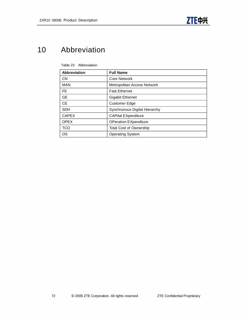
ZXR10 3900E Product Description
72 © 2009 ZTE Corporation. All rights reserved. ZTE Confidential Proprietary
10 Abbreviation
Table 23 Abbreviation
Abbreviation Full Name CN Core Network MAN Metropolitan Access Network FE Fast Ethernet GE Gigabit Ethernet CE Customer Edge SDH Synchronous Digital Hierarchy CAPEX CAPital EXpenditure OPEX OPeration EXpenditure TCO Total Cost of Ownership OS Operating System