ztc controls ltd. · converted locos will still run on any conventional pure dc controlled layout....
TRANSCRIPT

The ZTC System iexperie
It should only
Z24So
Tel: 08EW
If you fail to read ththat you could accidNOT covered by opotentially expensivinstructions before a
s only intended for controlling model railways bynced modellers over the age of 14 . ever be operated by young persons undercompetent adult supervision.
COPYRIGHT 2004
TC Controls Ltd. Chilkwell St. Glastonbury.merset BA6 8DB, England
70 241 8730 Fax: 01458 837831 Mail: [email protected] Site: www.ztccontrols.com
Issue 1.01
WARNINGe installation instructions properly it is possible
entally damage your ZTC unit. Such damage isur guarantee. So to prevent avoidable ande mistakes, please take the time to read thesettempting to install your equipment

ZTC Controls Ltd. 505 Manual
Page 2CONTROLS
Table of Contents
INTRODUCTION ...................................................................................................................5
1.0 Connecting Power to the ZTC 505...................................................................................81.1 Transformer Required ..................................................................................................81.2 Powering Up.................................................................................................................91.3 Fast Track Start-Up......................................................................................................9
ZTC 505 Controls and Panel Features ................................................................................10 Key to 505 Controls and Panel Features……………………………………………………....11
2.0 ZTC 505 Control Features .............................................................................................112.1 Keypad buttons ..........................................................................................................12
2.2 Command Keys ......................................................................................................122.3 Number Keys..........................................................................................................122.4 Enter Keys..............................................................................................................122.5 Entering Keypad Commands..................................................................................122.6 Command Key Look-up Table ................................................................................13
2.7 Loco controls..............................................................................................................132.8 Reverser Lever .......................................................................................................132.9 Regulator Lever ......................................................................................................132.10 Brake Handle........................................................................................................142.11 All Stop Button......................................................................................................14
3.0 Liquid Crystal Display (LCD) ......................................................................................143.1 Power Mode Indicators ..............................................................................................153.2 Current Indicator ........................................................................................................153.3 Overload ....................................................................................................................15
4.0 System Parameters .......................................................................................................164.1 Setting System Parameters .......................................................................................16
4.2 Scale and Gauge Settings......................................................................................16
5.0 Operating Our ZTC 505 .................................................................................................175.1 Loco Control Mode.....................................................................................................17
5.2 Changing Loco Control Mode.................................................................................185.3 Controlling a Locomotive Without a Decoder Installed...............................................185.4 Controlling Another Loco............................................................................................185.5 Switching Control Between Running Locos ...............................................................195.6 Loco Command Roster ..............................................................................................19
5.7 Saving Loco Parameters ........................................................................................195.8 Automatic Recall of Loco Roster on Start-up..........................................................205.9 Deleting the Saved Loco Roster .............................................................................20
5.10 Operating Decoder Functions ..................................................................................205.11 Double Heading and Multiple Units ..........................................................................21Note:- A break can only be done by the controller that is driving the group .....................21
6.0 Slave Controllers ...........................................................................................................216.1 Slave Controller Assignment ......................................................................................216.2 Setting up a Slave Controller and its Slave Number ..................................................22
7.0 What You Need to Know About Loco Decoders ............................................................23
ZTC Controls Ltd. 505 Manual
Page 3CONTROLS
7.1 Configurable Variables (CV) ......................................................................................237.2 Programming Track....................................................................................................247.3 First Time Loco Decoder Programming .....................................................................247.4 Programming Mode....................................................................................................247.5 Programming Locomotive Decoders ..........................................................................25
7.6 Verifying the Existing Value of a CV .......................................................................257.7 Resetting Loco Decoders to Factory Settings.........................................................25
7.8 ZTC 203, 205, 206, 213, 214, 215, 216, 217, 218, 226, 227 and 251…………...………257.9 ZTC 4000 Plug and Play Range Based on Standard Decoders………………………….26
7.10 CV 1 Locomotive Address or Number ................................................................267.11 CV 2 Start Voltage................................................................................................267.12 CV 3 and CV 4 Loco Acceleration and Deceleration ............................................277.13 CV 5 Max speed ...................................................................................................277.14 CV 6 Mid Step Speed ...........................................................................................277.15 CV 9 Output PWM Frequency ..............................................................................287.16 CV 12 Power Source Conversion .........................................................................297.17 CV 29 Basic Configuration Register .....................................................................307.18 CV 65 Kick Pulse..................................................................................................30
8.0 Advanced CV Options ...................................................................................................308.1 Changing Binary Bit Fields.........................................................................................30Use the ZTC 114 Decoder Slide Rule to assist in this type of calculation. .......................318.2 CV 12 Feature Table..................................................................................................318.3 CV 29 Feature Table..................................................................................................32
8.4 Extended Addressing .............................................................................................32
9.0 Accessory Decoders......................................................................................................339.1 Accessory Decoder Addresses ..................................................................................339.2 Operating Points with Accessory Decoders ...............................................................349.3 Operating Signals with Accessory Decoders .............................................................349.4 Multiple Aspect Signal Operation ...............................................................................349.5 Operating Other Accessories with Accessory Decoders ............................................359.6 Route Setting .............................................................................................................35
9.7 Setting up Accessory Presets.................................................................................359.8 Time Delays............................................................................................................369.9 Reviewing a Route .................................................................................................369.10 Editing Route ........................................................................................................379.11 Operating an Accessory Preset Route .................................................................37
10.0 Test and Calibration.....................................................................................................3810.1 Testing the Controls .................................................................................................3810.2 Calibrating the Controls............................................................................................3810.3 Transformer Test......................................................................................................3910.4 LED Test ..................................................................................................................39
11.0 Installation ...................................................................................................................4011.1 Power Input ..............................................................................................................40
11.2 Input Terminals.....................................................................................................4111.3 Optional DC Power Input ......................................................................................41
11.4 Recommended Track Wiring Gauge ........................................................................4211.5 Wiring the ZTC 505 Outputs to the Track(s). ...........................................................43
11.6 Multiple Track Feeds ............................................................................................4411.7 The Programming Track ..........................................................................................4411.8 Connecting Accessory Decoder Modules ................................................................44

ZTC Controls Ltd. 505 Manual
Page 4CONTROLS
11.9 Points & Turnouts.....................................................................................................4411.10 Large Layouts – Isolating Track Sections ..............................................................4511.11 Power Boosting ......................................................................................................45
12.0 Reverse Loops .........................................................................................................46
13.0 Over Temperature Protection...................................................................................46
14.0 Software Upgrades ......................................................................................................47
15.0 Alternative Decoder Programming Modes ...................................................................4715.1 Direct Mode..............................................................................................................4715.2 Physical Register Mode ...........................................................................................4715.3 Loco Address Verification ........................................................................................4815.4 Loco Address Programming.....................................................................................48
16.0 System Parameters..................................................................................................4816.1 Loco Speed Indicator ...............................................................................................48
17.0 Troubleshooting ...........................................................................................................49

ZTC Controls Ltd. 505 Manual
Page 5CONTROLS
INTRODUCTIONControlling a model railway with a simple variable resistance, or voltage, regulator has beenthe classic way of doing things since the introduction of the electric train set at thebeginning of the 20th century. Now there is the ZTC 505 Digital Controller, with RealFeel™controls that look and perform like the real controls of a traditional locomotive.
Running a RailwayVarying the voltage on the track to control a train is quite satisfactory for a simple layout.However, when it comes to larger layouts with a number of running lines and multiple trainoperation, you need a lot of switching and wiring to block sections to get the power frommultiple controllers to the right parts of the track. Add a reverse loop or whatever, andrunning one train alone can become quite complex. Running many engines, some on thesame track, becomes practically impossible using conventional DC.
What’s on the Track?With Digital Command & Control or DCC for short, power is on all of the track all of the time.DCC power is a low voltage digital AC signal. The actual regulation of the loco speed goeson in the loco itself. A decoder fitted inside the loco, converts the AC power to run the DCmotor of the loco.
So to control a loco, instead of varying the track voltage, a command is sent along the trackto the loco to tell it what speed it should be going at. This remote control means that youcan have as many trains in operation as you like without having to use block sectionswitching.
Simple WiringThis then greatly simplifies the wiring, especially for complex layouts. Since independentcontrol of locos on the same track is possible, you can have much more realistic operationswith double heading, banking and shunting.
More movementsThe most important benefit of digital operation is to not have to make numerous tracksection switching actions every time you want to move anything. You can now have moreenjoyment by letting out as many locos as you could wish whenever you want to.
More BenefitsThere are many other benefits of going DCC. The control is much smoother than you wouldexpect from a conventional controller, with very slow loco speeds being easy to achieve.You can also remotely operate auxiliary functions for each loco, such as lights, sound ,smoke effects or even electric couplers if you have them.
AccessoriesYou can control far more than the locos, if you desire. A remote controlled device, called anaccessory or stationary decoder, can be used to operate everything else on your layoutfrom the Master Controller. Also, points, signals and other motorised accessories can beeasily called-up from the keyboard, rather than relying on banks of electrical switches.Complexity of wiring is substantially reduced.

ZTC Controls Ltd. 505 Manual
Page 6CONTROLS
ControlThe controller in a DCC layout does much more than the old-fashioned boxes with a knob.It can handle a number of locos simultaneously, up to at least 12. You can start controlling any loco at once without having to switch power to the track. Afterkeying in a loco number, the controller will allow you to move a particular engine and run itright up to another stationery loco, couple up, and go off double headed or as a multipleunit. Similarly, you can bank or shunt realistically. But beware, you might be in danger ofhaving the worst prototypical accident - the head on collision!
Better ControlsThis is where RealFeel comes into its own. The regulator lever is much better for controllinglocomotives than rotary knobs. The controller also has a built-in memory to retain your set-up preferences.The FWD and REV indicators are provided to show present loco direction before control isseized or when inertia causes a lag in direction response.
Multiple Train ControlOne ZTC 505 can command up to 12 locos in motion at any one time from up to 9,999different loco numbers. A roster is maintained of the currently running engines so that onlyone button press is needed to swap between each one.
Additional slave controllers can be plugged into the rear of the master unit so that otherlocos can be simultaneously operated. These slaves can either be further ZTC 505 units orone or more of the Slave Hand Controllers. In this way, Up to 15 additional friends can helpoperate the railway and make it much more fun. Extension leads and sockets (ZTC 309)allow remote operation from 3 to 300 metres away!
Locomotive (Loco) decoders A locomotive decoder has to be fitted inside each loco or its tender to operate in digitalmode. The exception is that DCC does allow a single loco without any decoder ‘chip’ to berun on the system as if it had one. The function of these ‘chips’ is to receive the signals sentalong the track and control the power to the DC motor of the loco according to thecommands decoded. The power control is on-board the loco not in the controller. However,converted locos will still run on any conventional pure DC controlled layout. These will alsobe able to operate on other layouts powered by other manufacturers’ DCC controllers.
The decoders can be set-up for their loco addresses and all other characteristics from thekeyboard of the ZTC 505 by using the programming output connected to a short stub oftrack. There are no links or conductive paint needed. With 9,999 numbers to choose from,even the biggest loco collections can be catered for. The memory inside the decoderstoring the address and set-up characteristics is non-volatile and will remember its settingsfor more than 10 years and yet can be re-programmed as many times as necessary.
ZTC makes a complete range of these miniature remote control circuits of different shapes,sizes and power ratings. This will allow maximum flexibility in their application to differenttypes of loco, scale and gauge

ZTC Controls Ltd. 505 Manual
Page 7CONTROLS
How the System Works
To use the ZTC System you do not need to know any of the technicalities, but the basicsare: - The actual voltage on the track is in the range of 12 to 24 VAC according to the gauge orscale requirements. Superimposed on the track voltage is a digital signal containing thecommands to the various locos or accessory decoders on the layout.
Locos have a decoder between the power pickup from the wheels and the electric motor.The function of the decoder is to rectify the AC voltage on the track and convert it to DC foruse by the electric motor. A power controller stage smoothly varies the applied voltageaccording to the received commands decoded from the track signal by a small, dedicated,microprocessor. Direction is also controlled by the same stage and has nothing to do withthe polarity of the track.
Motor DriveMoving the unmodified (no decoder installed) loco is achieved by the controller varying thesymmetry of the AC voltage on the track so that a DC bias appears in one direction. Thecontroller uses a special address to control this mode, but for the user, it is as if the locoactually had a decoder!
In a decoder, the voltage control to the DC motor in a loco is achieved by pulse widthmodulation (PWM). This means that the on/off ratio of an electronic switch is varied, so thatthe average voltage can be controlled. This method is very power efficient, a factor thatmust be considered due to the tiny dimensions of the typical loco decoder. The frequency atwhich this is done is about 70 Hz, which is generally suitable for most commercial modelmotors. However, not all motors have the same characteristics and so the ZTC decodershave the ability to have the PWM frequency changed. Lower frequencies suit some largermotors better such as G and Gauge 1 models. The coreless precision motors such asPortescap and Faulhaber type vibrate too much at 70 Hz, but the decoder can be set to amuch higher frequency to suit them.
Power Boosting The ZTC 505 Master Controller has a maximum current output of 3.0 amps to the track.This is of course fed to all the track in parallel. The maximum power is drawn when locosare simultaneously starting, which might be double their nominal running currents.Accessory modules may also be connected to the track or the controller and taking poweras well. So eventually the system could ‘run out of steam’!
The power booster operates like an amplifier, taking the signal from the master controllerand providing a separate power output feed. This is connected to additional (remote) partsof the railway system and can provide up to another 5 amps of power. A separate mainstransformer has to be connected to the booster to provide its source of power. Moreboosters can be connected if even more power is needed.
ZTC Controls Ltd. 505 Manual
Page 8CONTROLS
9-17 VOLTSAC ONLY
TRACKO/P 1
TRACKO/P 2
PROGRAMTRACK O/P
ACCESSORYOPTION
SLAVECTLS
BOOSTERCTLS
D
CONNECTION KACTNTS+PG
– LOW VOLTAGE POW– TRACK NORTH OUT– TRACK SOUTH OUT– AUX +DC OUTPUT– AUX 0V. DC OUTPU
WARNING! DO NOT CONNECTTO LIVE MAINS SUPPLYWITHOUT ISOLATINGMAXIMUM INPUT VOLTAGE 17 VAC
AC +P G AC TS TN TS TNTS TN
AC MAINS SUPPLY
Rear of ZTC 505Controller
ZTC 560 TransformerUnit or Equivalent9 to 17 V AC Max.
9 to 17 VAC Max
Plug-in, 4-wayterminal block
Reverse Loops The main problem with a reverse loop is the fact that the left rail sweeps round to join upwith the right and visa-versa. To prevent short circuits an insulated joint must be placed atthe entry and exit of the loop. However, if the loop section is fed by a ZTC power booster(ZTC 550), continuous running will be possible through the loop. The booster senses thepolarity of the track signal needed and automatically switches itself at either the entry or exitas the train passes the insulated joint.
Additional material on the subject is available on the ZTC one hour DVD (ZTC 110) or theVideo (ZTC 111) DCC Expert Programme or In the Digital Command Control Book subtitled “DCC for beginners” written by Stan Ames, Rutger Friberg & Ed Loizeaux, which isalso available from ZTC Controls ltd. As product number ZTC 112
1.0 Connecting Power to the ZTC 505
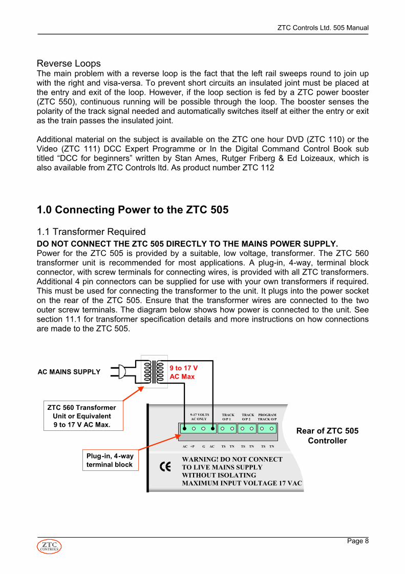
1.1 Transformer RequiredDO NOT CONNECT THE ZTC 505 DIRECTLY TO THE MAINS POWER SUPPLY. Power for the ZTC 505 is provided by a suitable, low voltage, transformer. The ZTC 560transformer unit is recommended for most applications. A plug-in, 4-way, terminal blockconnector, with screw terminals for connecting wires, is provided with all ZTC transformers.Additional 4 pin connectors can be supplied for use with your own transformers if required.This must be used for connecting the transformer to the unit. It plugs into the power socketon the rear of the ZTC 505. Ensure that the transformer wires are connected to the twoouter screw terminals. The diagram below shows how power is connected to the unit. Seesection 11.1 for transformer specification details and more instructions on how connectionsare made to the ZTC 505.
ZTC Controls Ltd. 505 Manual
Page 9CONTROLS
1.2 Powering UpThere is no power switch on the unit. Power is applied when the ZTC 560 transformer unitis connected to mains power. When power is applied to the unit, all the indicator lamps willilluminate for a brief period. Power on is indicated when one of the TRACK power indicatorsare lit continuously. The unit will also give a short "beep" to indicate that power is nowpresent on the output. The liquid crystal display (LCD) will also show a series of start-upmessages.
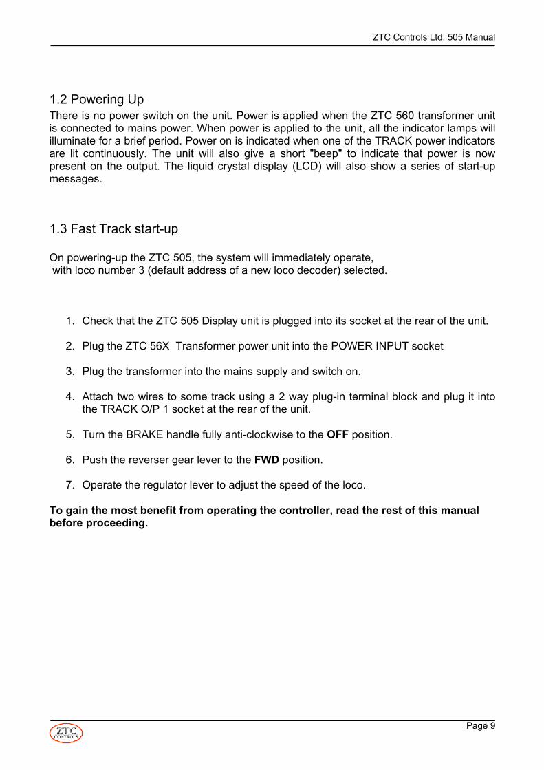
1.3 Fast Track start-up
On powering-up the ZTC 505, the system will immediately operate, with loco number 3 (default address of a new loco decoder) selected.
1. Check that the ZTC 505 Display unit is plugged into its socket at the rear of the unit.
2. Plug the ZTC 56X Transformer power unit into the POWER INPUT socket
3. Plug the transformer into the mains supply and switch on.
4. Attach two wires to some track using a 2 way plug-in terminal block and plug it intothe TRACK O/P 1 socket at the rear of the unit.
5. Turn the BRAKE handle fully anti-clockwise to the OFF position.
6. Push the reverser gear lever to the FWD position.
7. Operate the regulator lever to adjust the speed of the loco.
To gain the most benefit from operating the controller, read the rest of this manualbefore proceeding.

ZTC Controls Ltd. 505 Manual
Page 10CONTROLS
ZTC 505 Controls and Panel Features
511
DO
UB
LEH
EAD
ING
OVE
RLO
AD
CLE
AR
ZTC
505
Dig
ital
Mas
ter C
ontr
olle
rR
EM
OTE
CO
NTR
OL
INE
RTI
A
PR
ESE
T
SIG
NA
L
PO
INT
AU
TO
PR
OG
RAM
LOC
OO
FFO
NB
RA
KE
FUN
CTI
ON
1 2 3 4 5 6 7 8 9 0
SIM
ULA
TIO
N
SYS
TEM
DIG
ITA
LD
.C
CU
RR
ENT
TRA
CK
FWD
MID
RE
V
+
LR
ALL
STO
P
Loco
: 447
2
m
ph.+
70ZT
C 5
05 D
ispl
ay U
nit
CO
NTR
OLS
CO
NTR
OLS
32
4
1915
1816
1713
121011
91
76
58
EN
TER
14
1
OFF
OP
EN

ZTC Controls Ltd. 505 Manual
Page 11CONTROLS
9-17 VOLTSAC ONLY
TRACKO/P 1
TRACKO/P 2
PROGRAMTRACK O/P
ACCESSORYOPTION
PC SERIALSLAVECTLS
BOOSTERCTLS
DISPLAY
CONNECTION KEYACTNTS+PG
– LOW VOLTAGE POWER IN– TRACK NORTH OUTPUT– TRACK SOUTH OUTPUT– AUX +DC OUTPUT– AUX 0V. DC OUTPUT
WARNING! DO NOT CONNECTTO LIVE MAINS SUPPLYWITHOUT ISOLATING TRANSFORMER.MAXIMUM INPUT VOLTAGE 17VAC RMS
AC +P G AC TS TN TS TNTS TN
20 2221 23 24 25 26 27 28 29
Key to ZTC 505 Controls and Panel FeaturesKey Description
1 Display Unit tilt adjust screws2 Command keys3 Overload indicator LED4 Number keys5 Remote LED flashes intermittently when one or more slave
controllers are connected6 Program LED illuminates when in programming mode7 Automatic control LED - future application8 Liquid crystal display (LCD) screen9 Brake handle applies braking effort to loco
10 Double heading LED flashes when 2 or more locos are beinglinked as a multiple unit
11 Track power 12 Regulator lever controls the speed of a loco13 Direction indicator LEDs14 Reverser lever controls direction of loco15 Current indicator shows the amount of current being drawn from
the controller16 All stop button is used to stop all locos in an emergency17 Future Upgrade to ZTC 51118 Enter keys used for entering programming commands into the
controller19 Loco functions LED illuminates when loco function can be
keyed in directly20 Isolating power transformer – 9 to 17 V AC – input terminals21 DC power terminals for external DC power supply feed22 Output to track feed 123 Output to track feed 224 Programming track output25 Accessory connector – future application26 Slave controller connector27 Power booster connector28 Display unit connector 29 Computer port – future application

ZTC Controls Ltd. 505 Manual
Page 12CONTROLS
2.0 ZTC 505 Control Features The diagram of the ZTC 505 shows all the control features. The operation of each feature isdescribed below:
2.1 Keypad buttonsAll the keypad buttons are clustered on the left hand side of the ZTC 505 front panel.
2.2 Command KeysThe left hand column of grey push buttons is the Command keypad. Each key has acommand associated with it, which is printed beside it. These keys are used, in conjunctionwith other keys, to configure the ZTC 505 controller and any decoder modules that areinstalled in locomotives or connected to the ZTC 505 output.
2.3 Number KeysThe right hand column of grey push buttons is the Number keypad. The number zero (0)push button is also a command key (SYSTEM), The number keys are used in conjunctionwith other keys to configure the ZTC 505 and decoder modules.
2.4 Enter KeysOn the bottom left of the front panel are two buttons marked “L” and “R”. These are referredto as the and buttons. These buttons are usually pressed at theend of a sequence of key presses to enter a command into the ZTC 505 computer.
2.5 Entering Keypad Commands The entry of a sequence of keystrokes is represented by a list of command keys, or numberkeys, to be pressed in the order that each appears in the list. An arrow (→) is placedbetween each keystroke to more clearly show which key to press next. At no time arebuttons held down, or more than one button pressed at the same time.
Example:
The example indicates that the CONTROL button is pressed first, then the SIGNAL button,followed by the number 1 button and finally by the ENTER R button.
Where the entry requires the user to choose a numeric value (a loco number, or systemparameter number, for example), this is represented by words in bold lower case italics.
Example:
This translates into pressing the LOCO button first, followed by the desired loco number(e.g. 123) entered from the number keypad and then followed by the ENTER R button.The above convention is used throughout this manual.
If a mistake is made in keying in a sequence of commands, provided an ENTER key hasnot already been pressed, pressing the CLEAR button will abort the operation and allowyou to start again.
1 →→→CONTROL SIGNAL ENTER R
→ →LOCO loco number ENTER R
ENTER L ENTER R

ZTC Controls Ltd. 505 Manual
Page 13CONTROLS
2.6 Command Key Look-up TableThe back outside cover of this manual shows a quick reference table of command keyfunctions. Find the feature that you require in the body of the table. The first key to presswill be that shown opposite the feature, in the left hand column. The second key is thatshown above the feature in the top row. The “solo” column indicates that the only commandkey required is that shown in the left-hand column. You may have to enter a numeric valueafter the command key sequence, using the number keys, depending on the selectedfeature, followed by ENTER R.
2.7 Loco controlsRather than the conventional knob to control the speed of a loco, the ZTC 505 providescontrols similar to those used in a real locomotive. There is a regulator lever, a reverserlever and a brake handle. These represent the RealFeel™ feature of the ZTC 505controller.
2.8 Reverser Lever The reverser operates like a three position switch. The FWD and REV positions dictate thedirection of the currently selected loco. MID represents mid-gear on a steam locomotive, orneutral on a diesel or electric loco.
Moving the reverser lever rapidly from FWD to REV (or vise versa) causes inertia to beautomatically applied to the loco. The selected direction LED flashes slowly to indicate this.The loco will slow down, come to a halt and then move away in the opposite direction. Thissafeguard prevents abrupt changes in direction that could cause damage to locos and/orrolling stock.
2.9 Regulator LeverThe regulator lever is used to control the speed of the loco. Its immediate affect on thespeed of a loco depends on other settings of the ZTC 505 and the settings of the decodermodule in the loco concerned.
If inertia has been applied to a train, then moving the regulator to the OFF position will haveno immediate effect on a moving train. The train will coast for a while unless the BRAKE isapplied. If stopped and the regulator moved to the OPEN position, the train will slowlyaccelerate to the set speed.
When in the OPEN position, the regulator will only have affect if the REVERSER is fully inthe FWD or REV position.

ZTC Controls Ltd. 505 Manual
Page 14CONTROLS
DIGITAL
DC
TRACK
2.10 Brake HandleIf inertia is applied to a train (see section 5.8), setting the regulator to OFF will not stop thetrain immediately. The train will coast for a while, depending on the amount of inertiaapplied. The train can be brought to a controlled stop by applying the brake. This isachieved by rotating the brake handle clockwise to progressively apply more braking effort.An emergency stop is always applied if the brake handle is wound fully on (clockwise).
Note that if the brake handle is more than half way round, any effort to start a stationarylocomotive will be unsuccessful. Return the brake handle to the off position to start anyloco.
In addition to the above, the brake handle control can be used to dial in certain CV valuesduring programming steps, instead of using the number keys. See Section 15.5 for moredetails
2.11 All Stop ButtonIn pressing the ALL STOP button once will stop all locomotives. Power to the track is stillpresent and any accessory decoders connected to the track or track output connectors canstill be operated. Pressing the ALL STOP button for a second time cuts all power to thetrack.
To show that power has been cut, the TRACK power indicator shown at left,blinks and the LCD display will show "TRACK OFF/ALL HALTED".
3.0 Liquid Crystal Display (LCD)The ZTC 505 comes equipped with a display unit that plugs into the back of the ZTC 505.The display unit can be tilted by loosening the two Display Tilt Adjust screws located oneither side of the Display Unit with your fingers. Re-tighten the screws with your fingerswhen adjusted to your liking.
The display unit has a two-line LCD screen. The screen gives the user feedback whenoperating, or entering new commands into the system. When you are not enteringcommands, the top line of the display normally shows the loco number currently undercontrol, along with its speed.
Loco number and speed
ZTC Controls Ltd. 505 Manual
Page 15CONTROLS
3.1 Power Mode Indicators
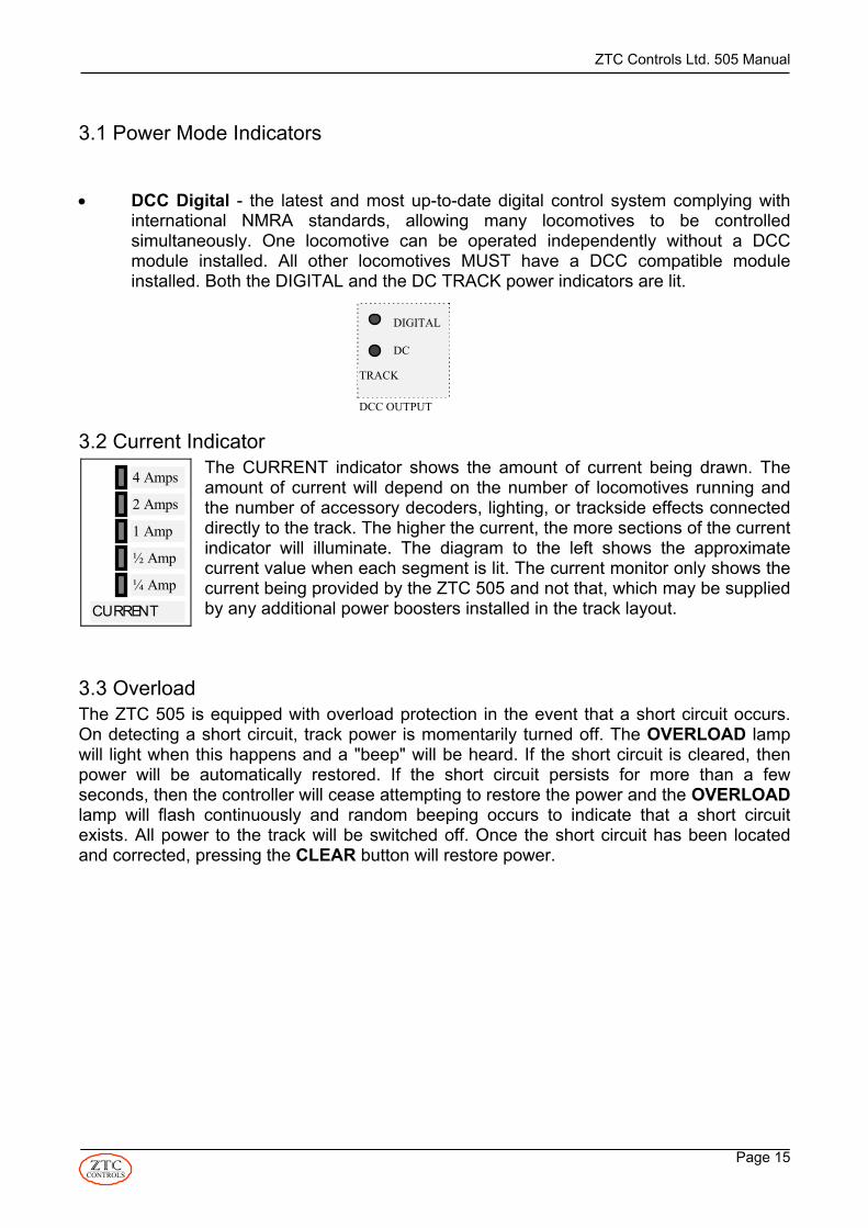
• DCC Digital - the latest and most up-to-date digital control system complying withinternational NMRA standards, allowing many locomotives to be controlledsimultaneously. One locomotive can be operated independently without a DCCmodule installed. All other locomotives MUST have a DCC compatible moduleinstalled. Both the DIGITAL and the DC TRACK power indicators are lit.
3.2 Current IndicatorThe CURRENT indicator shows the amount of current being drawn. Theamount of current will depend on the number of locomotives running andthe number of accessory decoders, lighting, or trackside effects connecteddirectly to the track. The higher the current, the more sections of the currentindicator will illuminate. The diagram to the left shows the approximatecurrent value when each segment is lit. The current monitor only shows thecurrent being provided by the ZTC 505 and not that, which may be suppliedby any additional power boosters installed in the track layout.
3.3 OverloadThe ZTC 505 is equipped with overload protection in the event that a short circuit occurs.On detecting a short circuit, track power is momentarily turned off. The OVERLOAD lampwill light when this happens and a "beep" will be heard. If the short circuit is cleared, thenpower will be automatically restored. If the short circuit persists for more than a fewseconds, then the controller will cease attempting to restore the power and the OVERLOADlamp will flash continuously and random beeping occurs to indicate that a short circuitexists. All power to the track will be switched off. Once the short circuit has been locatedand corrected, pressing the CLEAR button will restore power.
2 Amps
1 Amp
½ Amp
¼ Amp
CURRENT
4 Amps
DIGITAL
DC
TRACK
DCC OUTPUT

ZTC Controls Ltd. 505 Manual
Page 16CONTROLS
4.0 System ParametersThere are a number of parameter settings that you may want to change when first installingthe ZTC 505 system.
The Scale and Gauge Settings set the maximum voltage and current outputs from thecontroller. Depending on the scale of your layout these settings may need to be changed.The factory default settings are set for OO/HO scale.
The Loco Speed Indicator, displayed on the LCD screen, is set in speed steps. The speedsteps indicate the amount of power that the ZTC 505 is telling the loco decoder to apply tothe motor in the loco. Depending on the loco control mode (14, 28 or 128 steps – seeSection 5.1) Once set, the above settings are stored in the ZTC 505 and do not need to be set again,unless a change is required.
4.1 Setting System ParametersThe system parameters can be set by using the keypad buttons to key in the requiredinformation. To view the existing settings, key in:
The system will automatically return to normal operating mode after a few seconds.To reset the functions to factory settings, key in:
Note that there is no confirmation that a reset has taken place. You will have to view theparameters to confirm this.
4.2 Scale and Gauge SettingsUse the following keypad sequence to adjust the maximum voltage or limit the maximumcurrent available to the track:
This will have to be confirmed with another
The System Parameter Table provides the System Parameter Numbers, the parametereach relates to, and the range of new value figures that may be entered. The new value isentered in tenths of units e.g. for 1.0 Amp enter 10, for 16.0 Volts enter 160. See theRecommended Settings Table for recommended voltage and current settings for variousscales and system power modes. Note that the maximum voltage and current available is dependant on the rating of the lowvoltage transformer providing power to the ZTC 505.
→system parameter number→→SYSTEM FUNCTION ENTER R→PRESET new value→
ENTER R
→→SYSTEM FUNCTION ENTER R
→→SYSTEM FUNCTION ENTER R→9 → 9

ZTC Controls Ltd. 505 Manual
Page 17CONTROLS
System Parameter TableSystemParameterNumber
SystemParameter
FactorySetting
RecommendedMinimum
RecommendedMaximum
1 Maximum trackvoltage
14 Volts 90 (= approx 9Volts)
255
2 Maximum outputcurrent
63(5 Amps
max.)
10(= 1.0 Amp)
63 in UK fordigital mode.
Recommended SettingsScale/Gauge Output Voltage
Parameter 1Output Current Limit
Parameter 2DCC Digital
OO/HO 14 VAC set 140 3.5 Amps set 44 (Max)N 12 VAC set 120 3 Amps set 30O 17 VAC set 170 3.5 Amps set 44 (Max)
G or Gauge 1 >20 VAC set 255 3.5 Amps set 44 (Max)Z 10 VAC set 100 2 Amps set 20
5.0 Operating your ZTC 505
Note that one locomotive without a decoder can be operated in DCC mode. This isassigned address 0, or loco number 0. See Section 5.2 for more details.To gain control of a locomotive you need to know the address or loco number that has beenassigned to it. The following keystrokes allow you to gain control of a locomotive:
The selected loco number will appear in the top left of the LCD screen. Start the locomoving by setting the reverser to the desired direction and adjust the regulator for speed.For new decoders use the number 3 which is the default value.
5.1 Loco Control ModeThe ZTC 505 can be configured to send speed control signals to a loco decoder in one ofthree modes. These are the 14 step, 28 step and 128 step modes. The higher the numberof steps, the smoother and more precise the speed control. The default control mode is 28step. ZTC loco decoders (version 2 and above) can operate in all three modes. Somemanufacturers’ loco decoders do not support the 28 or 128 step modes. If a loco, with a nonZTC loco decoder installed, shows flashing headlights when accelerating, it is an indicationthat the decoder does not support the control mode currently set for that loco. The controlmode would need to be changed. To view the currently set control mode for a given locopress:
→ →LOCO loco number ENTER R
→ →CONTROL CONTROL ENTER R
ZTC Controls Ltd. 505 Manual
Page 18CONTROLS
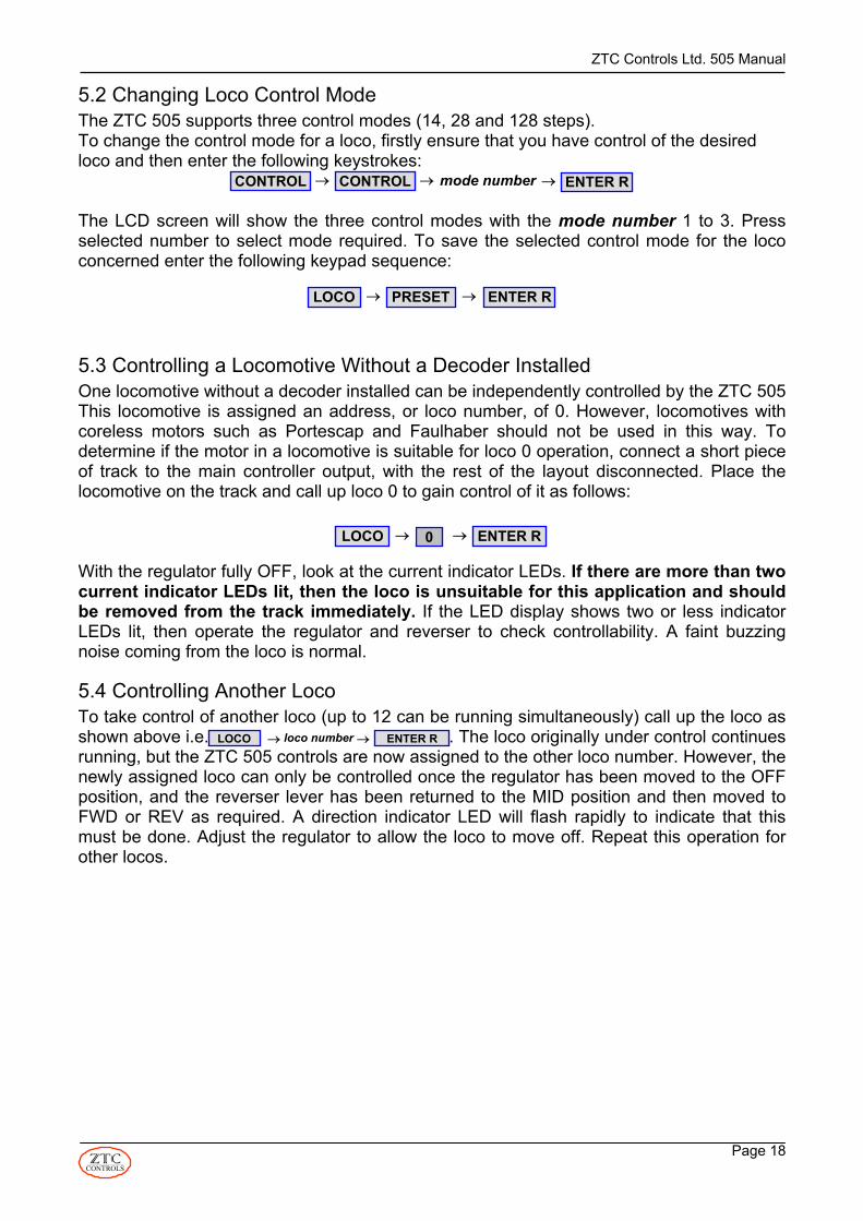
5.2 Changing Loco Control ModeThe ZTC 505 supports three control modes (14, 28 and 128 steps). To change the control mode for a loco, firstly ensure that you have control of the desiredloco and then enter the following keystrokes:
The LCD screen will show the three control modes with the mode number 1 to 3. Pressselected number to select mode required. To save the selected control mode for the lococoncerned enter the following keypad sequence:
5.3 Controlling a Locomotive Without a Decoder InstalledOne locomotive without a decoder installed can be independently controlled by the ZTC 505This locomotive is assigned an address, or loco number, of 0. However, locomotives withcoreless motors such as Portescap and Faulhaber should not be used in this way. Todetermine if the motor in a locomotive is suitable for loco 0 operation, connect a short pieceof track to the main controller output, with the rest of the layout disconnected. Place thelocomotive on the track and call up loco 0 to gain control of it as follows:
With the regulator fully OFF, look at the current indicator LEDs. If there are more than twocurrent indicator LEDs lit, then the loco is unsuitable for this application and shouldbe removed from the track immediately. If the LED display shows two or less indicatorLEDs lit, then operate the regulator and reverser to check controllability. A faint buzzingnoise coming from the loco is normal.
5.4 Controlling Another LocoTo take control of another loco (up to 12 can be running simultaneously) call up the loco asshown above i.e. . The loco originally under control continuesrunning, but the ZTC 505 controls are now assigned to the other loco number. However, thenewly assigned loco can only be controlled once the regulator has been moved to the OFFposition, and the reverser lever has been returned to the MID position and then moved toFWD or REV as required. A direction indicator LED will flash rapidly to indicate that thismust be done. Adjust the regulator to allow the loco to move off. Repeat this operation forother locos.
→→ →CONTROL CONTROL ENTER Rmode number
→ →LOCO PRESET ENTER R
0→ →LOCO ENTER R
→ →LOCO loco number ENTER R

ZTC Controls Ltd. 505 Manual
Page 19CONTROLS
5.5 Switching Control Between Running LocosAs loco numbers are entered, the ZTC 505 stores these numbers in its memory locationcalled the Loco Command Roster (see Section 5.5). To switch control to another loco in theroster, simply press the ENTER R or ENTER L keys to scroll up or down through the storedloco command roster. When you arrive at the desired loco number, after a brief pause, theZTC 505 will automatically assign control to that loco. The desired loco number will appearat the top left of the LCD screen.
Alternatively, you may enter the desired loco number directly by calling it up using thecommand and number keys:
If the previously controlled loco is running in the opposite direction to that of the newlyselected loco, the direction indicator LEDs, either FWD or REV, will blink slowly, showingthe direction in which the newly selected loco is currently running. Move the reverser levertowards the blinking LED and position the regulator to adjust the speed. Whilst the directionindicator is blinking, a heavy inertia is applied to the selected loco, so that a sudden changein speed or direction is avoided when a loco switch is performed.
5.6 Loco Command RosterUp to 12 locomotive numbers can be retained in the loco command roster.(Only 12 locomotives can be operating at the same time). If a 13th loco number is entered,the ZTC 505 will search for the first loco that is halted, delete it from the roster, and thenadd the new loco to the roster. If all 12 locos are in motion, the system will halt the first locoin the roster, delete it, and then replace it with the new loco number. If you do not want thisto happen, then you can remove a loco number from the roster manually by using thefollowing keypad sequence:
5.7 Saving Loco ParametersThe Loco Command Roster also stores the various parameters set up for individual locos.These are the Step control mode and the Maximum speed. When a loco is called up, theZTC 505 checks its roster for a match against the loco number. If it finds a match, then theparameters that were set are recalled for that loco. If parameters are required to bechanged, or stored initially for a new loco, then set the required parameters for the loco, asdescribed in other parts of this manual, and then enter the following key sequence to savethem in the roster memory:
The saved roster can be recalled at any time by pressing:
→ →LOCO loco number ENTER L→CONTROL
→ →LOCO PRESET ENTER R
→ →LOCO ENTER RFUNCTION
→ →LOCO loco number ENTER R

ZTC Controls Ltd. 505 Manual
Page 20CONTROLS
5.8 Automatic Recall of Loco Roster on Start-upThe ZTC 505 can be configured to automatically recall features of the last saved loco rosterwhenever it is powered up.
To view the available options key in:
Three options will be shown on the LCD screen.
• Select 1 to recall the last loco used at the previous operating session.• Select 2 to recall the whole loco roster used at the last operating session.• Select 3 to not recall any locos on start up at all.
Follow your selection with
5.9 Deleting the Saved Loco RosterThe information about all the locos stored in the roster can be deleted by keying in thefollowing sequence:
5.10 Operating Decoder FunctionsSome loco decoders, in addition to controlling the speed and direction of the loco, have anumber of auxiliary functions. These can be used to operate lights, smoke generators, orsound, for example. When a new loco is selected, the LED below the FUNCTION button is illuminated. Thisindicates that any number entered from the number keys will immediately operate therelated function output; one press for ON and another for OFF. Once another command keyis depressed the FUNCTION LED will go off and the immediate access to the number keysfor operating the various functions is no longer available.
Accessing a loco decoder function is then performed by using the following keystrokes:
Depending on the state of the selected function, this will turn it on or off.
Once a function has been called up in this way, the FUNCTION LED stays illuminated andimmediately pressing a function number on the keypad will toggle that feature on and off.However, as before, if another command button is depressed the FUNCTION LED will goout and immediate access to a function is no longer available. To regain access, repeat theabove keystroke sequence.
Refer to the information provided with the loco decoder to determine the function numbersavailable. More information on decoder function programming will be found in theinstructions supplied with the decoder.
FUNCTION LOCO→
ENTER R
→LOCO → ENTER RPOINT
ENTER R→→FUNCTION function number or ENTER L

ZTC Controls Ltd. 505 Manual
Page 21CONTROLS
5.11 Double Heading and Multiple UnitsTwo or more locos can be operated together as a multiple unit, providing both locomotivesare on the Active Loco Roster. This is called double heading. To create a multiple unit oftwo locos simply key in the numbers of the required locos as follows:
Up to five locos can be linked together by repeating the LOCO commands before pressingthe ENTER R key. On pressing the ENTER R key the controller will be assigned to thatgroup, the lead loco number being the number displayed on the LCD screen, preceded bythe letters DH (Double Heading). The Double Heading indicator LED will be flashing.Up to eight double headed pairs can be operating at once (only 16 locos can be runningsimultaneously).
To reselect a double headed group after controlling another loco, simply recall the lead loconumber, by either scrolling through the loco roster (using ENTER R or ENTER L keys), orcalling it up directly (LOCO → loco number → ENTER R). Note that none of the other locosthat are part of the group will be able to be recalled using the scrolling technique.
When a multiple unit group is reselected the double heading symbol will appear on the LCDdisplay but the double heading LED will not flash.
To break up a multiple unit press the following keys:
To remove an individual loco from the group and control it individually simply reselect it asfollows:
Note:- A break can only be done by the controller that is driving the group
6.0 Slave ControllersA slave controller allows an additional operator to control trains on the layout. Several slavecontrollers can be connected to the ZTC 505, which is then referred to as the mastercontroller. The REMOTE LED on the ZTC 505 will blink intermittently when one or moreslaves are attached to the master. The following keystrokes set the controller to be a slave.
6.1 Slave Controller AssignmentZTC 505 Slave Controllers have a unique slave number that is set up on the slave keypadonce it is connected to the master. The slave number cannot be changed from the mastercontroller.The status of all controllers (slaves and master) can be reviewed by using the followingkeystrokes on the ZTC 505:
→LOCO lead loco number 2nd loco number→LOCO → ENTER R→
CONTROL → →LOCO ENTER R
→ →LOCO loco number ENTER R
→ →CONTROL ENTER R SYSTEM
→ 6 →CONTROL ENTER R SYSTEM

ZTC Controls Ltd. 505 Manual
Page 22CONTROLS
Pressing repeatedly shows each of the loco - controller assignments used on thesystem. Locos that are not under direct control of any controller are indicated as FREE. Toexit this display mode press .
For more information on slave controllers see the individual slave controller instructionmanual.
6.2 Setting up a Slave Controller and its Slave NumberThe ZTC 505 Master controller should be powered up on its own, with no connections to thetrack.
Set the controller to work as a slave.
Set the slave number for the controller by entering:
The slave number must be between 1 and 30 inclusive.
Note:- Slave numbers 0 and 31 are not available.
To view the current slave number for the ZTC 505 press:
Important Note;- When powering up the designated Slave ZTC 505 use of a separatepower transformer is recommended. Alternatively use a separate lead from the sametransformer as used for the Master ZTC 505 controller. In this case you will need to add asecond connector to the output of the transformer wired the same way round as the first.
If this is not done then the controller will appear to work for a short time, but will possiblydamage the XBus III cable and/or the master ZTC 505 due to excess load on the powersupply. Data is then passed between the two controllers using an XBus III lead connectedbetween the Slave outputs of the two ZTC 505s.
ENTER R
CLEAR
→CONTROL → ENTER RSlave Number
→CONTROL ENTER R

ZTC Controls Ltd. 505 Manual
Page 23CONTROLS
7.0 What You Need to Know About Loco DecodersFor independent operation of several locos on the layout, each loco needs to have a locodecoder installed (except loco 0, see Section 5.3). A loco decoder contains a miniaturecomputer chip that responds to commands (speed up, slow down, turn on lights, etc.) sentto it along the rails of the train track. All the decoders on the layout receive their commandsin this way, so a mechanism has to be applied so that an individual decoder knows whatcommands it should respond to, and what commands it should ignore. To achieve this,each decoder has a unique electronic address or loco number assigned to it. Commandsfor a specific decoder are preceded by its electronic address, telling the decoder that thecommands that follow the address are for it to respond to. New decoders all have the sameaddress or loco number (3) which is their default setting, so the first step after installing adecoder in a loco (see specific decoder installation instructions) is to change the loconumber to something different from all the other decoders on the layout. There are otherfeatures in loco decoders that can be changed as well. Each of them, including the loconumber, is referred to as a Configurable Variable, or CV.
7.1 Configurable Variables (CV)A list of important CVs is shown in the table below. Some decoders have more CVs. Not allof the CVs listed apply to all decoders. See the data sheet supplied with your decoder fordetails. Some of the listed CVs are explained in greater detail elsewhere in this manual. Alist of available CVs can be viewed on the LCD screen by keying in the following:
Pressing or scrolls though the list of CVs, which also shows theirrespective description, where applicable.
CV # DESCRIPTION Default MIN. MAXZTC
Notes
1 Primary Loco Address 3 1 127 Some decoders supportextended addressingup to 9999
2 Vstart 8 0 255 not practical above 1283 Fixed Loco Acceleration Rate 0 0 154 Fixed Loco Braking Rate 0 0 155 Vhigh Loco Top Speed 255 15 255 don’t use below 156 Vmid Speed Curve modifier 0 8 250 0 = feature off9 Total PWM Period See table in Section 7.15
12 Power Source Conversion17 Extended Address, high order
bits0 0 63 advanced users only
18 Extended Address, low order bits 0 0 255 advanced users only29 Basic Configuration Register 2 0 3 see table in Section 8.365 Kick Pulse 0
POINT → LOCO → ENTER R
ENTER R ENTER L

ZTC Controls Ltd. 505 Manual
Page 24CONTROLS
7.2 Programming TrackTo perform any change to a CV requires that a special programming track be connected tothe ZTC 505 (see Section 11.7). The loco containing the decoder to be changed is placedon this track. More than one loco on the track may result in both decoders beingprogrammed the same, or not responding at all. The programming track is isolated from allother parts of the layout, so that other decoders do not get re-programmed unintentionally.The programming track also allows small current pulses generated by the decoder, inresponse to certain commands, to be fed back to the controller as confirmation thatcommands have been received and executed. Whenever a programming command isentered on the ZTC 505 keypad the programming track becomes active and the power tothe rest of the layout is automatically disconnected. Another feature of the programmingtrack is that the current fed to it is limited to approximately 100 mA, just in case there is awiring fault with a newly installed decoder. Damage to a decoder is less likely whencurrent is limited. The programming track is fed normal power when the ZTC 505 is not inthe programming mode.
7.3 First Time Loco Decoder ProgrammingBefore you put any loco on your programming track for the first time it is advisableto first cut-off all track power by pressing the button twice, or using a trackisolation switch, if installed. Once the loco has been placed on the track, pressto reset the track isolation switch to restore power to the track.
This ensures that, should there be any wiring fault with a newly installed decoder, there isless likelihood of any damage being done to the decoder by the full track power level. Alimited power level is applied to the programming track during each programming orverification attempt. Full power to the layout can be restored, after programming iscompleted, by pressing , and confirming with an .
7.4 Programming ModeWhenever any of the programming keystrokes are entered, the ZTC 505 goes into theprogramming mode. This is indicated by the PROGRAM light emitting diode (LED) flashing.When the programming sequence has finished, the message Pgm. Finished will appear onthe LCD screen followed by the ALL HALTED message. More programming keystrokescan be entered at this time.
To return the ZTC 505 to normal operating mode press the button and then confirmwith an .
CLEAR
CLEAR ENTER R
CLEAR
ENTER R
ALL STOP

ZTC Controls Ltd. 505 Manual
Page 25CONTROLS
7.5 Programming Locomotive DecodersThere are two main modes for programming locomotive decoders. These are the E1 or“paged mode” and the E2 or “direct mode”. The “paged mode” is the ZTC preferredmethod and will be used as the principal programming method in this manual. Somemanufacturers’ decoders may not respond to the “paged mode”. If you experience difficultyin programming a decoder refer to Section 15.0 for a list of commands used in the “directmode” and some programming “tricks” for certain brands of decoder.
Unless otherwise indicated, all CVs can be programmed using the following keystrokes:
Where cv number is the CV number desired and new value is a number, the value ofwhich depends on the CV being programmed. See Section 7.1 for a list of important CVnumbers.
Example: To programme CV 1 (loco address) to 82 use the following:
7.6 Verifying the Existing Value of a CVTo verify a value of a CV use the following keystrokes:
Where cv number is the number of the desired CV. For example, if you wanted to verify theloco address of a decoder the cv number would be 1.
7.7 Resetting Loco Decoders to Factory SettingsThere may be occasions when an incorrect CV value is stored in a decoder, which couldrender a decoder inoperable. Or, you may wish to re-use a decoder in a different loco andwould prefer to return CV’s to known values. Under these circumstances the resettingfeature is especially useful. The method of resetting ZTC loco decoders to factory settings.The method used depends on the type of decoder concerned.
7.8 ZTC 203, 205, 206 , 213, 214, 215, 216, 217, 218, 226, 227 and 251Reset these decoders using the following keystrokes:
A
And confirm with another
As the restore process proceeds, the LCD screen may on some decoders display anincreasing number of right chevrons (>). When complete the LCD screen will display“Finished” followed by “ALL HALTED”.
Press and to return to normal control mode.
POINT → LOCO cv number → ENTER Rnew valuePRESET →→→
POINT → LOCO cv number → ENTER R→
1 8POINT → LOCO → ENTER RPRESET →→→ 2→
PRESET POINT Decoder number I.E ZTC 214 ENTER R→
ENTER R
CLEAR ENTER R

ZTC Controls Ltd. 505 Manual
Page 26CONTROLS
7.9 ZTC 4000 Plug and Play Range are based on the standard Decoders.
ZTC Plug and Play Number Base Decoder Number
ZTC 4001 ZTC 214ZTC 4002 ZTC 226ZTC 4003 ZTC 213ZTC 4004 ZTC 216ZTC 4005 ZTC 226ZTC 4006 ZTC 216
Reset these decoders using the following keystrokes:
As the restore process proceeds, the LCD screen may on some decoders display anincreasing number of right chevrons (>). When complete the LCD screen will display“Finished” followed by “ALL HALTED”.
Press and to return to normal control mode.
For decoders not listed here, refer to the decoder instructions.
7.10 CV 1 Locomotive Address or NumberWhen shipped from the factory, all decoders have CV 1 set to 3. This means that thedecoder will respond to loco number 3.
To change the loco number, you change the value of CV 1 to a number between 1 and 127.Note that loco numbers from 128 to 9999 can be used if the loco decoder supportsthe extended address option and the option is enabled. See Section 8.4 for moredetails.
7.11 CV 2 Start VoltageThis sets the proportion of full power that the decoder uses as a base level for the firstspeed step. It is intended to be just enough to keep the motor turning at its lowest possiblespeed. A perfect motor would work well with 0, but to overcome motor and mechanismfriction a small to modest value will improve the control range. Poorer motors will demanda higher figure. It can only be found by experimentation for a given model.
On ZTC decoders, numbers 0 to 255 are possible although if it needs numbers above 100,it would suggest that the model has considerable friction! Other makes of decoder may usedifferent values for this CV (see decoder instructions).
PRESET POINT Decoder number I.E ZTC 4001 Enter ZTC 214 ENTER R→
CLEAR ENTER R

ZTC Controls Ltd. 505 Manual
Page 27CONTROLS
7.12 CV 3 and CV 4 Loco Acceleration and DecelerationWhen the controller sends speed commands to the loco, if the CV 3 and CV 4 values areboth 0, the response will be fast and may look jerky. By introducing acceleration anddeceleration factors, the loco decoder smoothes out the speed steps. However, if thefigures are too high, the response of the loco may be too sluggish. Some experimentation isneeded to find the best compromise for a particular loco. On ZTC decoders the numberrange is 0 to 15 with 15 being the slowest response.
7.13 CV 5 Max speedThis sets the proportion of full power that can be applied to the motor on the top regulatornotch (speed step) and therefore limits the top speed of the loco. Some locos do not everneed full power and so if this value is reduced from its maximum value you will get betterspeed control over the operating range
On ZTC decoders the range is 0 - 255 with 255 being the full power value. If zero is everset the loco will never move. A lower practical limit is about 32 for very sensitive motors.
7.14 CV 6 Mid Step SpeedWhen this value is zero the control speed curve for the power delivered to the motor islinear from the start voltage, set with CV 2, to the maximum speed, set with CV 5. However,setting CV 6 to somewhere between the two values will bend the power curve, generallyimproving the low end control range if the value of CV 6 is set below half the maximumspeed value (see V mid B in the diagram below).
For advanced users another CV exists in ZTC decoders to move the break point positionalong the speed step axis. The Vmid step at CV 25 is set to 0 by default and this sets thebreak point half way along the speed step scale, as shown in the diagram below. However,the value of CV 25 can be changed from 1 to 13 to vary the break point position along thespeed step axis.

ZTC Controls Ltd. 505 Manual
Page 28CONTROLS
7.15 CV 9 Output PWM FrequencyChanging the value in CV 9 allows the motor drive pulse width modulation (PWM)frequency to be changed. The factory default value is 216, which sets a frequency of about69 Hz. This value suits most DC motors. Larger motors benefit from lower frequencies.Experiment for the value most suited to your locos.
Coreless motors, such as Portescap and Faulhaber, should be run at 32 kHz. Set CV9value to 0 for the best performance for these motor types. Do not run larger can or openframe motors with CV 9 below 190.
POWEROUT
255
191
127
630
Max Power Level
Max Speed set on CV 5
Start Voltage set on CV 2
Basic Speed Steps from ControllerMAX
Regulator Response Modification using CV 6
0 1 2 3 4 5 6 7 8 9 10 11 12 13 14
Regulator responsewith CV 6 set to 0
Regulator responsewith CV 6 set to B
A
B
Regulator responsewith CV 6 set to A
Break point set on CV 25
V mid
V mid

ZTC Controls Ltd. 505 Manual
Page 29CONTROLS
CV 9value
PWMFreq Hz
Notes CV 9value
PWMFreq Hz
Notes
255 31 123 523251 33 119 561247 35 115 604243 38 111 654239 41 107 714235 45 103 786231 49
LARGEMOTORS
99 874227 55 95 980223 61 91 1046
LOW POWERPRECISIONMOTORS
219 65 83 1208216 69 DEFAULT 79 1309215 70 75 1429211 75 71 1572207 82 67 1748203 89 63 1961199 98 59 2092195 109 55 2242191 123 51 2415187 131 47 2618183 140 43 2857179 151 39 3145175 164 35 3497171 179 31 3922167 197 27 4184163 219 23 4484159 245 19 4831155 262 15 5236151 280 11 5714147 302
MOSTSMALLMOTORS
7 6289143 327 3 6993
USE EXTERNALFILTER WITHSMALL MOTORS
139 357 2135 393 1 NOT TO BE USED
131 437 0 32 kHz PORTESCAP MOTORS
127 490
LOWPOWERPRECISIONMOTORS
7.16 CV 12 Power Source ConversionThis enables the decoder to respond to analogue power (DC), if DCC signals are notpresent. If you never require (DC), it is better to reset CV 12 to 1 If CV 12 is set to 0, only DCC operation is possible. This can speed up restarts after badcurrent collection situations such as dirty track or dead frogs.See Section 8.0 for more details on how to set CV 12 options.

ZTC Controls Ltd. 505 Manual
Page 30CONTROLS
7.17 CV 29 Basic Configuration RegisterThe default value for CV 29 for ZTC decoders is the value 2. If you get the motor wiring thewrong way round (setting the ZTC 505 to a forward direction results in the loco goingbackwards), it can be fixed without rewiring the loco by changing the CV value to 3. SeeSection 8.0 for more details on how to set CR 29 options.
7.18 CV 65 Kick PulseCV 65 sets the duration of an extra pulse of power to the motor when the controller tries tostart the loco from rest. If used with a value greater than 0, it helps overcome the initialstarting friction (sometimes called stiction). Experiment for best results.
8.0 Advanced CV OptionsInformation is stored in a CV in binary form (a series of 1s and 0s). Each CV has thecapacity to hold eight 1s or 0s (bits). Some CVs use all eight bits to store a single decimalnumber (CV 2 for example). The range of decimal numbers it can store is from 0 to 255.Other CVs store information relating to the 0 or 1 state of individual bit fields. In this casethe 0 or 1 state of a bit field determines if a feature is enabled (1) or disabled (0). In thisapplication the bits are called “control bits”. Up to eight features can be controlled by oneCV in this way. However, if you wish to enter a decimal number into such a CV, you haveto calculate bit fields to be sure that the desired bits are set appropriately to enable ordisable desired features. It is far more convenient if you have access to each individual bitfield and can set the bits according to desired features.
8.1 Changing Binary Bit FieldsFor CV 10 and higher, the ZTC 505 has the capability of changing the state of individual bitfields. This saves the inconvenience of calculating bit fields for the more involved CVs likeCV 12 and CV 29. This is especially useful for programming ZTC sound decoders.
To view the current bit status of a CV use :
To access the bit field entry mode use the following keystrokes:
Where cv number is the CV required to be changed and set bits is when you set each ofthe eight bits by using the number keys 0 to 7, which toggle each bit on or off. The LCDscreen displays all the bits as off or dashes by default. If a bit is set to on (1) the number ofthat bit is displayed in its correct position in the 8 bit sequence on the LCD screen. If a bit isset to off (0) a dash appears in its place. The equivalent decimal number is displayed to theright of the bit fields. When all the bits are set as desired, pressing ENTER R completes theoperation and enters the changes into the CV.Example:
POINT → LOCO cv number → ENTER Rset bits→→→ SIGNAL
1POINT → LOCO → ENTER R→→→ 29 SIGNAL → 5
POINT → LOCO cv number → ENTER R→
ZTC Controls Ltd. 505 Manual
Page 31CONTROLS
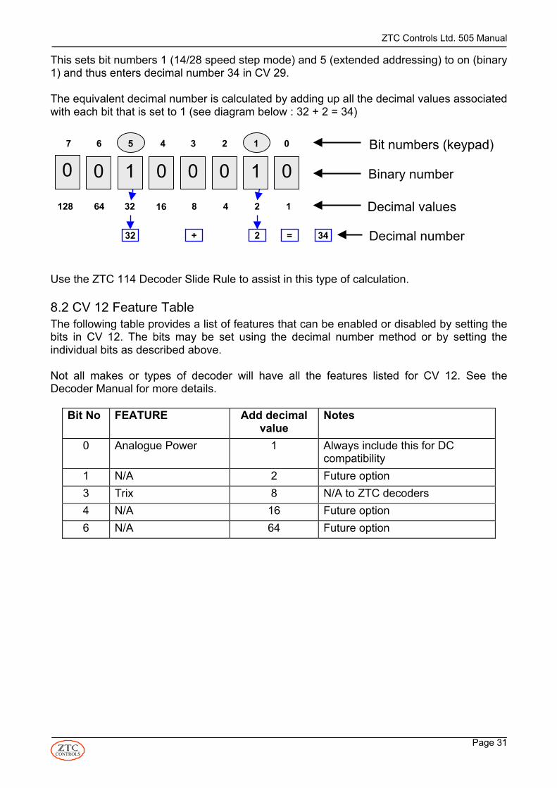
This sets bit numbers 1 (14/28 speed step mode) and 5 (extended addressing) to on (binary1) and thus enters decimal number 34 in CV 29.
The equivalent decimal number is calculated by adding up all the decimal values associatedwith each bit that is set to 1 (see diagram below : 32 + 2 = 34)
Use the ZTC 114 Decoder Slide Rule to assist in this type of calculation.
8.2 CV 12 Feature TableThe following table provides a list of features that can be enabled or disabled by setting thebits in CV 12. The bits may be set using the decimal number method or by setting theindividual bits as described above.
Not all makes or types of decoder will have all the features listed for CV 12. See theDecoder Manual for more details.
Bit No FEATURE Add decimalvalue
Notes
0 Analogue Power 1 Always include this for DCcompatibility
1 N/A 2 Future option3 Trix 8 N/A to ZTC decoders4 N/A 16 Future option6 N/A 64 Future option
0 1 00 0 1 001234567
1248163264128
0Bit numbers (keypad)
Binary number
Decimal values
32 2+ = 34 Decimal number

ZTC Controls Ltd. 505 Manual
Page 32CONTROLS
8.3 CV 29 Feature TableThe following table provides a list of features that can be enabled or disabled by setting thebits in CV 29. The bits may be set using the decimal number method or by setting theindividual bits as described above.
Bit No FEATURE Add value Notes0 Loco Direction Reverse 1 Set this if the loco runs the
wrong way round due to a wiringmistake
1 14/28 Speed Step mode 2 If NOT set the decoder is in thecoarse 14 step control modewith directional light control.
2 Analogue Power 4 Always include this for DCcompatibility
3 Advanced decoderacknowledgement
8 Future option only
4 Speed table used 16 Not supported by all decoders.See Manual for details.
5 Extended addressing 32 When set, decoder can expectloco addresses 128- 9999
6 N/A 64 future option7 Accessory Decode
Enable128 Decoder operates with
accessory commands andignores loco commands
8.4 Extended AddressingThe normal address range for DCC decoders is 1 to 127 inclusive. This is set in CV 1.Enabling extended addressing allows loco numbers of 128 to 9999 to be used. This wouldallow a complete loco cab side number to be used, making it very easy to know what a locoaddress is. To access extended addressing requires that the extended address (loconumber greater than 127) to first be entered into the CVs that save the address. These areCV 17 and CV 18. Once this has been done then the extended address feature has to beenabled by setting bit field number 5 to 1 in CV 29.
Use the following keystrokes:
This entry will have to be confirmed with another Wait until the programming sequence has completed (a little longer this time as CV 17 and CV 18 are both being programmed, one after the other) and ALL HALTEDappears on the LCD screen, then key in the following to view how CV29 is already set.
ENTER R
POINT → LOCO → ENTER RPRESET →→→ new loco number1 → 7
POINT → LOCO ENTER R→→ 2 → 9
ZTC Controls Ltd. 505 Manual
Page 33CONTROLS
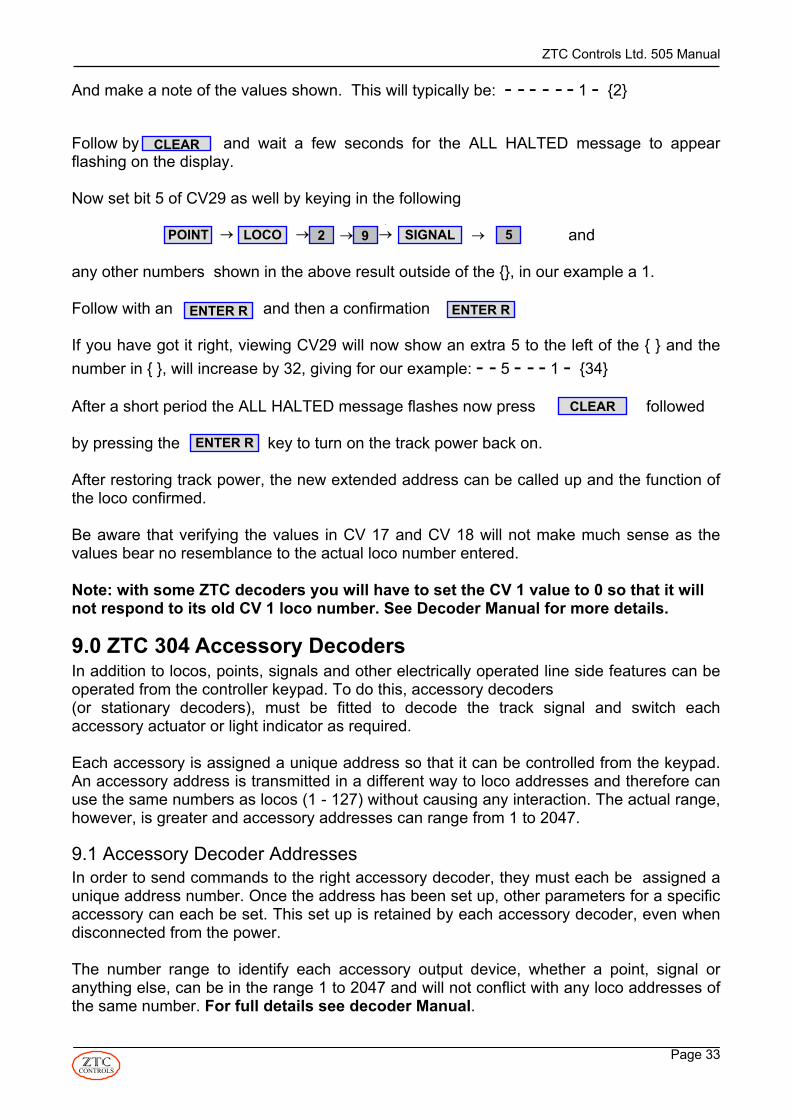
And make a note of the values shown. This will typically be: - - - - - - 1 - {2}
Follow by and wait a few seconds for the ALL HALTED message to appearflashing on the display.
Now set bit 5 of CV29 as well by keying in the following
and
any other numbers shown in the above result outside of the {}, in our example a 1.
Follow with an and then a confirmation
If you have got it right, viewing CV29 will now show an extra 5 to the left of the { } and thenumber in { }, will increase by 32, giving for our example: - - 5 - - - 1 - {34}
After a short period the ALL HALTED message flashes now press followed
by pressing the key to turn on the track power back on.
After restoring track power, the new extended address can be called up and the function ofthe loco confirmed.
Be aware that verifying the values in CV 17 and CV 18 will not make much sense as thevalues bear no resemblance to the actual loco number entered.
Note: with some ZTC decoders you will have to set the CV 1 value to 0 so that it willnot respond to its old CV 1 loco number. See Decoder Manual for more details.
9.0 ZTC 304 Accessory DecodersIn addition to locos, points, signals and other electrically operated line side features can beoperated from the controller keypad. To do this, accessory decoders (or stationary decoders), must be fitted to decode the track signal and switch eachaccessory actuator or light indicator as required.
Each accessory is assigned a unique address so that it can be controlled from the keypad.An accessory address is transmitted in a different way to loco addresses and therefore canuse the same numbers as locos (1 - 127) without causing any interaction. The actual range,however, is greater and accessory addresses can range from 1 to 2047.
9.1 Accessory Decoder AddressesIn order to send commands to the right accessory decoder, they must each be assigned aunique address number. Once the address has been set up, other parameters for a specificaccessory can each be set. This set up is retained by each accessory decoder, even whendisconnected from the power.
The number range to identify each accessory output device, whether a point, signal oranything else, can be in the range 1 to 2047 and will not conflict with any loco addresses ofthe same number. For full details see decoder Manual.
→POINT → LOCO SIGNAL→→ 2 → 9 5→
CLEAR
ENTER R ENTER R
CLEAR
ENTER R

ZTC Controls Ltd. 505 Manual
Page 34CONTROLS
9.2 Operating Points with Accessory DecodersTo operate a single point on any accessory decoder module key in:
or
Pressing or will alternately operate the point to the left or right.However, this definition depends on the actual wiring and configuration applied to theaccessory module. You can follow-on with another point by simply keying the accessoryaddress and Or.
DO NOT TOGGLE SOLENOID DEVICES FOR PROLONGED PERIODS AS MOSTSOLENOID POINT MOTORS ARE NOT DESIGNED FOR CONTINUOUS DUTY. YOUCOULD BURN OUT THE MOTOR!
9.3 Operating Signals with Accessory DecodersTo operate a single signal on any accessory decoder module key in:
(red – on) or (green - off)
Pressing or , will alternately operate a signal whether a two aspectcoloured light or a solenoid actuated semaphore .
For basic signals, the convention should be that puts it on to RED or caution and to GREEN or off.
You can follow-on with another signal by simply keying the number and or
.
9.4 Multiple Aspect Signal OperationFor these commands to work, the accessory decoder concerned must have beenpreviously set up with output mode CV’s each set for individual control.
Multiple aspect coloured light signals are connected to two consecutive accessory decoderoutputs but can be operated by a single command.
To operate a pair of accessory decoder module outputs together, key in:
POINT → → ENTER LAccessory address ENTER R
ENTER RENTER L
ENTER L ENTER R
→ ENTER Raccessory address→SIGNAL
ENTER R
ENTER R
ENTER L
ENTER L
1st accessory address→SIGNAL FUNCTION→ function number→ →
ENTER R or ENTER L
ENTER L
ENTER L
ENTER R

ZTC Controls Ltd. 505 Manual
Page 35CONTROLS
Where function number is the signal function number shown in the table below.
SIGNALFUNCTION
Address NRED GREEN
Address N + 1 AMBER AMBER
LIGHTASPECT
4 Both OFF Both OFF Out of action11 * 1 ON 2 OFF Both OFF RED12 * 1 OFF 2 ON Both OFF GREEN13 * Both OFF Both ON DOUBLE
AMBER14 * Both OFF 1 ON 2 OFF SINGLE
AMBER15 Both ON Both ON Test function0 OFF/ON no change special function1 OFF/ON no change special function2 no change OFF/ON special function3 no change OFF/ON special function* If ENTER R is pressed again the function number is incremented to the nextsignal indication & similarly ENTER L decrements.
9.5 Operating Other Accessories with Accessory DecodersTo operate any accessory connected to a decoder module, whatever the output operates,you first press or followed by the accessory address number.
Pressing or will alternately operate the function on or off, left or rightor otherwise. However this definition depends on the actual wiring and configurationapplied to the accessory module controlled.
9.6 Route SettingThe ZTC 505 allows several accessories to be operated with a single keyed-in number.This allows a route to be set, where all the points/signals required to be set to allow a trainto follow a particular route will be thrown automatically, one after the other. A group ofaccessories, which is required to be operated in this way, is called an Accessory Preset.
9.7 Setting up Accessory PresetsA preset allows more than one accessory to be operated from a single keyed-in number. Toset up an accessory preset, first check the operation of each of the items you want tocontrol and write down their addresses and which way you want them to operate (left, right,on, off etc.). Use the following key sequence to set up an accessory preset:
ENTER L
POINT SIGNAL
PRESET → ENTER R→ PRESET → preset number
ENTER R

ZTC Controls Ltd. 505 Manual
Page 36CONTROLS
Where preset number is any number from 1 to 255. Then operate each accessory functionin the order and direction you wish it to occur in the preset set up as follows:
Each time this is done, another accessory is added to the PRESET. To delete the previous step (in the case of an error) key in.
At the end of the sequence, which must contain at least one step, press:
This will save the preset sequence.
9.8 Time Delays When a signal is added to a preset, an automatic delay of about one quarter of a second(0.25) will occur before the next step is operated. When a point is added to a preset, thedelay is automatically set to about 2 seconds to allow for power supply recovery before thenext successive accessory operation. These preset time delays can be changed for a stepby inserting the following keystrokes after entering a step:
Where time delay is any number between 1 and 63, giving the time delay required, inseconds. This delay will be inserted between each successive event until a new time valueis keyed in or a new preset is commenced.
9.9 Reviewing a RouteYou can review the status of a Route by pressing:
Firstly this shows the total number of presets already stored and the total number of stepsthey use in memory. Then the numbered preset is shown, step by step, as accessorynumber, state (1 or 0) and time delay.
POINT → → ENTER Raccessory address or ENTER L or
PRESET → ENTER R→ PRESET
PRESET → ENTER L→ PRESET
INERTIAPRESET → time delay→
→FUNCTIONPRESET → preset number → ENTER R
SIGNAL → → ENTER Raccessory address or ENTER L as required.

ZTC Controls Ltd. 505 Manual
Page 37CONTROLS
9.10 Editing RouteOnce saved, your Route operation becomes permanently stored in the controller until youdecide to delete it. Editing of a stored Route is not possible. To change a Route, deleteit, then recreate it correctly.
A single route can be deleted by keying in:
You will be asked to confirm the deletion by pressing .
To delete the entire route memory contents key in:
You will be asked to confirm the deletion by pressing .
9.11 Operating an Accessory Preset RouteTo operate an accessory preset route use the following key sequence:
The points and/or signals will be set in a sequential operation, which is indicated by a beepas each is operated. Each step of the preset is flagged in the bottom left hand corner of theLCD display, if time permits.
Note that to reverse the sequence (return the route to its previous state) requires thecreation of another preset.
If the preset number entered has not yet been set up, the display will indicate NOT SAVED.
The storage space for routes is limited on the ZTC 505 to 2 with a total number of 16presets per route. When the memory space is full, you will get a PRESET MEMORY FULLmessage.
PRESET → preset number → ENTER L
ENTER R
CONTROLPRESET → ENTER R→
ENTER R
PRESET → preset number → ENTER R

ZTC Controls Ltd. 505 Manual
Page 38CONTROLS
10.0 Test and CalibrationThe controls on the ZTC 505 are precision monitored by the internal processor for optimumresults. From time to time it is recommended to check the controls in case of any slightmechanical drift of the end stop positions. If you find the regulator no longer gives 100% fullpower or the reverser no longer works properly, re-calibration may be necessary.
10.1 Testing the ControlsTo test the controls, disconnect all power from the track by turning off any track isolationswitches, or pull out the plugs to the TRACK O/P1, O/P2 receptacles and programmingterminals on the rear of the ZTC 505.
Then key in:
You can then see the values each control produces.
CONTROL MINVALUE
MAXVALUE
Note
REGULATOR 0 255 There is a small deadband at the beginning oftravel
REVERSER -127 +127 There is a small deadband in the mid positionwith an indent this shouldread 0
BRAKE 0 255 Does not need to becalibrated
If any control does not operate over the range shown above, the unit needs to be re-calibrated.
10.2 Calibrating the Controls The controls are calibrated by first keying in:
Then, follow the displayed instructions to move each control to each extreme position,ignoring the displayed numbers. The sequence is:
Set the Regulator lever to OFF positionSet the Reverser lever fully FWD then press Set the Reverser lever fully REV then press Set the Reverser lever to MID positionSet the Regulator lever fully OFF then pressSet the Regulator lever fully OPEN then press
→2→→→CLEAR SYSTEM ENTER RPRESET
→1→→→CLEAR SYSTEM ENTER RPRESET
ENTER RENTER R
ENTER R
ENTER R

ZTC Controls Ltd. 505 Manual
Page 39CONTROLS
By this process, the system memorises the positions of the end-stops.The LCD screen will now be displaying the values associated with the position of eachcontrol. Check that the values displayed match those in the table when each control ismoved to its extremes. To confirm if all controls are correctly positioned mechanically, key in the following:
Four figures will be shown briefly on the LCD screen. If any one of them reads 0, then thecontrols need mechanical adjustment. This should not be attempted by an inexperiencedoperator. The unit should be returned to ZTC for re-calibration.
10.3 Transformer TestThe ZTC 505 is able to estimate the voltage of the transformer powering it, to determine ifthe voltage value is in an acceptable in range. This is performed by pressing the followingkeys:
The value displayed is an estimate of the AC RMS output voltage of your transformer withonly a light loading (about 250mA). If it is too high, the display will say so. An exceptionallyhigh supply voltage to the unit could do internal damage or cause rapid overheating. Pressing CLEAR will exit the test function.
10.4 LED TestAll the front panel LED indicators, except the REMOTE LED, can be forced on for testing bykeying:
Disconnect power from the controller to return it to normal operational mode or press
to return to the main menu.
→SYSTEM ENTER R→3PRESET →
SIGNAL →→FUNCTION ENTER R
INERTIA SIGNAL →→ ENTER R
ENTER L

ZTC Controls Ltd. 505 Manual
Page 40CONTROLS
11.0 InstallationYou should have the following items to enable installation:
Item Quantity Required ZTC Part No.Two Way Terminal Block 2 supplied with unit ZTC 028Four Way Terminal Block 1 supplied with transformer ZTC 030Twin white wire (seeTable of RecommendedWire Gauge). Example either 42 x 0.2mmstranded orequivalent copper wirewith cross section area ofat least 1 sq. mm. ZTC100 wire is ideal.
Not supplied ZTC 100 10 meters Rated at 10AmpsPVC Covered 42 x 0.2mm
Screw Driver with 3mm flatblade
Not supplied (Item not supplied)
AC Mains transformerwith 12- 17 volt output atleast 2 amps min AC.
1 ( or more if ZTC 550Booster units are to be used)
ZTC 56X Transformer12 or 15 Volts AC at 5amps max.
11.1 Power InputWARNING: A DOUBLE INSULATED TRANSFORMER, PROVIDING A LOW VOLTAGEOUTPUT NOT EXCEEDING 17 VAC, MUST BE USED TO POWER THE ZTC 505.TRANSFORMERS MUST COMPLY WITH BRITISH STANDARD BS415 class 2EN600065 EN60-772, OR OTHER EQUIVALENT STANDARD PUBLISHED BY UL, CSAOR OTHER STANDARDS AGENCY.
The input power requirements of the ZTC 505 is low voltage only. Never attempt to directlyconnect live mains supply to the unit. A low voltage mains transformer or power supplymust be used. The ZTC 560 is the recommended supply transformer for most UKapplications.A user provided transformer must meet the relevant safety standards. See the TransformerRecommendations table for recommended voltage and current ratings for different layoutscales. A transformer of a higher current rating than that listed, is acceptable as it willgenerally give better regulated power. If too high a voltage is used to power the unit, it willcause internal damage.
DO NOT CONNECT MAINS VOLTAGES DIRECTLY TO THE ZTC505. THIS WILL RESULT IN AN ELECTRIC SHOCK HAZARDAND WILL DESTROY THE UNIT

ZTC Controls Ltd. 505 Manual
Page 41CONTROLS
Transformer Recommendations for UK Operation(A range of products for other countries is available)
SCALE / GAUGE OUTPUT VOLTAGE OUTPUT CURRENT ZTC PART
OO / HO 15 VAC 2 to 5 amps or more ZTC 560N 12 VAC 1.5 to 3 amps or more ZTC 562O 15 VAC 1.5 to 5 amps or more ZTC 560G or Gauge 1 15 to 17 VAC 5 to 10 amps ZTC 564Z 10 to 12 VAC 1.5 to 2 amps or more ZTC 566
11.2 Input TerminalsWhen connecting to the POWER INPUT terminal block, use wire ofsufficient rating (e.g. ZTC 100) as recommended in the Table ofRecommended Wire Sizes (See Section 11.4). The 4 way, plug-in,terminal block, supplied with the ZTC 505 transformer, provides aconvenient removable connection. Always connect the transformeroutput to the two outer connections of the 4 terminals, It doesn’tmatter which way round the wire goes from the transformer as it is AC aslong as it is in the two outer connections of the 4 way connector block.Check that there is no exposed copper wires or ‘whiskers’ at the strippedend of your wires where they go into the block. Clamp the wires using asuitable screwdriver. Do not over tighten. Do not attempt to apply power
without using the 4 way terminal block.
The two inside connections are not to be normally used. They provide either anunregulated DC output from the unit’s internal rectifier or a means of providing DC powerinput.
11.3 Optional DC Power Input
This is an option you can ignore if you are using a transformer.As an alternative, an external DC low voltage power supply can be usedto power the ZTC 505 using the G (ground) and +P (+ve power)terminals. It should be 12 to 24 volts, regulated DC only. A capacity of 1.5to 5 amps will be needed depending on your operational requirements.The supply should be suitably fused with an anti surge type fuse, notexceeding 5 amps. If the polarity is connected incorrectly, your fuse willblow and you may damage the ZTC 505.
The advantage of DC power supply operation is that the internal powerdissipation is reduced, promoting cooler running at high output power levels.
AC +P G AC
20
9-17 VOLTS AC ONLY
AC +P G AC
21
9-17 VOLTS AC ONLY

ZTC Controls Ltd. 505 Manual
Page 42CONTROLS
11.4 Recommended Track Wiring GaugeThe wires used to connect to the track should be of a size and type suitable for the type andscale of railway and the maximum number of locos intended to be run. If the wires are toothin, there will be an increasing voltage drop along the wire, as the number of running locosincreases. This causes poor loco operation.
With digital operation it is probable that the number of locos will grow from the initial phase.So it is better to use the heaviest recommended gauge wire for the job at the outset. Seethe table for more information. ZTC supply a self adhesive copper tape (ZTC 320) which israted at 20 Amperes and ideal for all gauges. A flexible connection cable (ZTC 100), ratedat 10 Amperes, is also available.
There are two terminal sockets at the rear of the unit marked, TRACK O/P 1 and TRACKO/P 2. These are identical and wired in parallel internally. Their use allows multiple feedsto spread the load to the track rather than using a single cable. Alternatively, one socketcan feed the track and the other can feed any accessory decoders.
TABLE OF RECOMMENDED WIRE SIZESExpected maximum output current for ZTC 505. If wiring run distance is more than 10Metres (30ft) use the next heaviergauge of wires
TRACKCONNECTIONS
1 to 2 amps 2 to 3 amps 3 to 4 amps 5 amps (max)
Single pair cablefeed orTransformer input
16 x 0.2mm(0.5 sq. mm) or1 x 1.13mm(1 sq. mm)
23 x 0.2mm(0.75 sq. mm) or1 x 1.13mm(1 sq. mm)
32 x 0.2mm(1.0 sq. mm) or1 x 1.38mm(1.5 sq. mm)
32 x 0.3mm or42 x 0.2mm(1.5 sq. mm) or1 x 1.38mm(1.5 sq. mm)
2 cable feeds 7 x 0.2mm(0.22 sq. mm)or1 x 0.6mm(0.28 sq. mm)
16 x 0.2mm(0.5 sq. mm) or1 x 1.13mm(1 sq. mm)
23 x 0.2mm(0.75 sq. mm) or1 x 1.13mm(1 sq. mm)
32 x 0.2mm(1.0 sq. mm) or1 x 1.13mm(1 sq. mm)
3 cable feeds 7 x 0.2mm(0.22 sq. mm)or1 x 0.6mm(0.28 sq. mm)
7 x 0.2mm(0.22 sq. mm) or1 x 0.6mm(0.28 sq. mm)
16 x 0.2mm(0.5 sq. mm) or1 x 1.13mm(1 sq. mm)
23 x 0.2mm(0.75 sq. mm) or1 x 1.13mm(1 sq. mm)
Programming trackoutput
Separate stubof track:16 x 0.2mm(0.5 sq. mm) or1 x 1.13mm(1 sq. mm)
If siding is partof running line:16 x 0.2mm(0.5 sq. mm) or1 x 1.13mm(1 sq. mm)
If siding is partof running line:16 x 0.2mm(0.5 sq. mm) or1 x 1.13mm(1 sq. mm)
Notrecommended
Transformer feedto ZTC 505 ACvoltage supplyinput
23 x 0.2mm(0.75 sq. mm)or1 x 1.13mm(1 sq. mm)
23 x 0.2mm(0.75 sq. mm) or1 x 1.13mm(1 sq. mm)
32 x 0.2mm(1.0 sq. mm) or1 x 1.38mm(1.5 sq. mm)
32 x 0.3mm or42 x 0.2mm(1.5 sq. mm) or1 x 1.38mm(1.5 sq. mm)
Multi-strand wire sizes shown as “number of strands x strand diameter” with equivalent crosssectional area. Single core wire is shown as “1 x wire diameter” with equivalent cross sectionalarea.

ZTC Controls Ltd. 505 Manual
Page 43CONTROLS
11.5 Wiring the ZTC 505 Outputs to the Track(s).The following diagram illustrates the recommended method of connecting the ZTC 505 tothe track.
13.5 Output TerminalsZTC terminals are labelled TN for TRACK NORTH and TS for TRACK SOUTH as aconvention. On an ordinary DC controller, the NORTH rail would be on the right side andpositive polarity with a loco going forwards. Your wiring and track configuration should notallow NORTH to make contact with SOUTH or else you will have a permanent short circuit!When operating in DIGITAL mode the track polarity has no effect on the direction of runningas it would for ordinary DC operations.
The plug-in 2 way terminal blocks, supplied with the ZTC 511, provide a convenient way ofconnection. Use a 3mm (1/8”) width flat bladed screwdriver when tightening up theterminals screws. Do not over tighten. Check that there is no exposed copper or ‘whiskers’of wire at the stripped end of your wires where they go into the blocks.
You may insert multiple track connections into each terminal block for either TRACK O/P1or TRACK O/P2. You do not have to use both outputs and they are interchangeable. Whenthe controller is used in ordinary DC mode or PWM, both these outputs are still the same.NB: There is no common return from the TN TS pairs of terminals and any otherinput or output terminals. They should both be regarded as “Live” although theoutput voltage is less than 25 Volts.
13.6 Wiring the Main LineThe length of the wiring from the TRACK O/P 1 and 2 should be minimised to avoid unduevoltage drops in the cable. On most layouts, the track alone cannot be relied on to carry thepower signals to all parts of the system. Rail joiners are particularly poor electricalconductors and may cause reliability problems if the layout does not have multiple feeds.
Good electrical integrity between the controller and all trackwork is extremely important forsuccessful DCC digital operation. Since current in the system can be quite high whenoperating multiple trains, the wire used should be more substantial than for a conventionallayout. Dirty track and poor rail joints will not reliably pass the data signals and commands,carried on the AC track voltage to the locomotives.
It is strongly recommended that the main current to the track be carried by at least one ringmain pair of wires located under the layout surface. ZTC recommends ZTC 320, a selfadhesive copper tape, rated at 20 Amperes.For best results use nickel-silver track.
9-17 VOLTSAC ONLY
TRACKO/P 1
TRACKO/P 2
PROGRAMTRACK O/P
ACCESSORYOPTION
SLAVECTLS
BOOSTERCTLS
DISPLAY
CONNECTION KEYACTNTS+PG
– LOW VOLTAGE POWER IN– TRACK NORTH OUTPUT– TRACK SOUTH OUTPUT– AUX +DC OUTPUT– AUX 0V. DC OUTPUT
WARNING! DO NOT CONNECTTO LIVE MAINS SUPPLYWITHOUT ISOLATINGTRANSFORMER.MAXIMUM INPUT VOLTAGE 17 VACRMS
AC +P G AC TS TN
AC MAINS SUPPLY
Programming TrackFor DCC
Both rails isolated fromthe rest of the layout.
Rear of ZTC 505Controller
ZTC 560 TransformerUnit or Equivalent9 to 17 V AC Max.
9 to 17 VAC Max
TS
TN
Connect to trackapprox. every 1 metre
To more trackand/or accessory
decoders (optional)
Basic Track and Power Connections
Main Line
Plug-in, 4-wayterminal block
3 x ZTC 010 DPDTswitches for isolating
track sections
ZTC 011 trackpower indicatorlamp (optional)
Programming trackcan be a siding, or athrough track isolated
at both ends
TS TNTS TN

ZTC Controls Ltd. 505 Manual
Page 44CONTROLS
11.6 Multiple Track FeedsRunning at least one tape or cable pair round your layout and tapping off to the track withcopper wire (ZTC 321) at regular intervals will promote good power integrity. The distancebetween feeds can vary depending on the gauge and average track lengths. One tapping ordropper per metre (36-40”) or so is prudent for N and OO/HO. For gauge 1 this might belengthened to 2 metres or so (6-7 feet). If the interval between feeds is too far, it will showitself in reduced performance between the feed points. With the power bus, it will be easy toadd extra feeds when it appears to be needed.
When installing droppers be careful not to mix up the TRACK NORTH and SOUTH wiringpolarity, as this will create a short circuit across the track.
11.7 The Programming TrackThe programming output from the controller is used for setting up the loco decodersinstalled in the locos. This is not relevant if you only use the controller in slave mode toanother unit.
The PROGRAM TRACK output is derived from the same source as the TRACK O/P 1 and2. It can therefore feed any separate siding, stub, or through track on your layout. In theprogramming mode of operation, an internal relay within the ZTC 505 disconnects the restof the layout and only the programming track remains energised at a low power level. Thisallows the set-up of a loco with decoder when it is placed on this special section. It shouldbe conveniently close to the controller.
11.8 Connecting Accessory Decoder Modules Generally these take their signal information from the same source as a loco decoder andtherefore can be connected to either TRACK O/P 1 or 2. They can also be fed by taking atap off the track feed or the track itself. See the information that comes with the AccessoryDecoders for full installation instructions.
11.9 Points & TurnoutsBoth insulated and live frog points may be used with the DCC system (e.g.: Peco "Insul-frog" and "Electro-frog"). Live frogs are better as they promote better continuity over thecrossings, especially at low speeds. However, a small amount of extra work, wheninstalling, will be necessary, as the rails into the frog must be insulated from the continuingrails to prevent shorts as the blades switch over. The track power is fed from the toe as inconventional practice. Both following rails should be wired so as to be permanently live.When using insulated frog points, the switch blade usually disconnects the opposing side'srail. Unless you particularly require an isolated siding, bridge wires should also be fitted tokeep both sides live.

ZTC Controls Ltd. 505 Manual
Page 45CONTROLS
With some types of insulated frog point certain locos cause problems due to excessive tyrewidth. These can cause occasional short circuits as they pass over the frog. The ZTC 505controller will automatically reset itself from such a trip condition and carry on running. Toavoid this situation occurring, these points can be treated the same as live frog types, withinsulated joints to both frog rails and a bridge wire connected from each end of the pointsection. For more information on point and layout wiring contact our help desk or have alook at www.wiringfordcc.com
11.10 Large Layouts – Isolating Track SectionsWhen the ALL STOP button on the controller is pressed twice, all power is cut off from thetrack. However, it is recommended that a track isolating switch be installed between thecontroller outputs and the track. On large layouts, if you do get a short circuit for somereason, it will be easier to locate if each of the major sections of the layout has an isolatingswitch to disconnect the power from the controller. Any switch used for track isolation needsto have wiping contacts rated at 5 Amps at 24 volts AC, double pole, single throw. Both TNand TS should be switched. The ZTC 010 is the ideal switch for this purpose. An indicatorlamp, ZTC 011, may also be fitted if required.
11.11 Power Boosting The ZTC 505 Master Controller has a maximum power output of 3 Amps. The maximumpower is drawn when locos are simultaneously starting which might be double their nominalrunning currents. Accessory modules may also be connected to the track power as well. Soeventually the system could ‘run out of steam’.
The ZTC 550-power booster operates like an amplifier, taking the signal from the mastercontroller and providing a separate power output feed. This is connected to additional(remote) parts of the railway system and can provide up to another 5 amps of power. Aseparate mains transformer has to be connected to the booster to provide it with power.More boosters can be connected should even more power be needed.

ZTC Controls Ltd. 505 Manual
Page 46CONTROLS
The loop must beIsolated at both ends
To ZTC-505 MasterController
To low voltagetransformer
Track feeds
ZTC-550 Power Booster
12.0 Reverse Loops The main problem with a reverse loop is the fact that the TRACK NORTH rail sweeps roundto join up with the TRACK SOUTH rail and vice-versa, causing a short circuit. To preventthe short circuit, insulated joints are placed at the entry and exit of the loop.
However, if the loop section is fed by a ZTC 550 power booster, continuous running will bepossible through the loop. The booster senses the phase of the track signal needed andautomatically switches itself at either the entry or exit as the train passes the insulated joint.One booster could serve two or more reverse loops on the layout provided only one train isever expected to pass in or out of any loop at one time.
Installation information is given in the ZTC 550 Manual.
13.0 Over Temperature ProtectionDuring normal operation, heat is generated by the electronic components inside the ZTC 505 cabinet. If the unit has been operating for extended periods of time, at excessivecurrent levels, then there is the possibility that internal temperatures may reach values thatcould affect the performance of the ZTC 505 circuitry. This is especially so if the ambienttemperature is high. The ZTC 505 is protected against such an event. If the temperaturereaches a critical level, then the output will automatically shut down, to prevent thishappening. The message "OVER TEMPERATURE" will be displayed on the LCD screen foras long as the output is shut down. Once the temperature has dropped to a safe level, theoutput will be automatically restored.
(ZTC 562)

ZTC Controls Ltd. 505 Manual
Page 47CONTROLS
14.0 Software UpgradesFurther ZTC research and development will in the future provide new and/or enhancedfeatures for the ZTC 505 controller, which will be made available to existing users assoftware upgrades. The ZTC 505 can also be upgraded to the specification andperformance of its big brother the ZTC 511 for full details of this please contact ZTCControls Ltd.
15.0 Alternative Decoder Programming ModesAs discussed earlier, there are two main methods for CV programming. One is the preferredPaged Mode and the other is the Direct Mode. If a decoder does not respond to thePaged Mode, try the Direct Mode or a third method called Physical Register Mode. Thereare also different methods for verifying the value of a CV. Note that in all instances the loconeeds to be on the programming track.
15.1 Direct ModeUse the following keystrokes to change CV values:
The cv value can be any number 0 to 255, except in the case of CV 1 (loco address), whichis restricted to 1 to 127.
To verify the present value of a CV use the following key sequence:
The controller will take a few seconds to scan the decoder and retrieve the CV value, whichwill be displayed on the LCD screen. If you want to repeat the test, just pressagain. To exit the verify mode press or .
15.2 Physical Register ModeIn Paged Mode, some older non ZTC makes do not page properly nor will they work in theDirect Mode. Their physical registers (the equivalent of CVs) can all be directly accessedby keying numbers 2001 to 2008 to correspond to 1, 2, 3, 4, 5, 6, 7 and 8. The decoderprogramming is then the same as for Paged Mode using these +2000 CV numbers. Thespecific instructions for the decoder should be followed, which may be different, in numberrange and usage, from ZTC or other NMRA compliant types.
PRESET → ENTER R→ cv number→ PRESET→ → cv valueLOCO
PRESET → ENTER R→ cv number→LOCO
ENTER R
ENTER L CLEAR

ZTC Controls Ltd. 505 Manual
Page 48CONTROLS
15.3 Loco Address VerificationIn addition to using the Paged or Direct Modes for verifying CV 1 (loco address) there aretwo other methods. For the first one use the following keystrokes:
The second method requires that you use the following:
The second method will not work if the loco address is between 113 and 127, or if the motorcurrent is too small to be detected. This may work for older decoders from Marklin 2 rail,Arnold and Lenz.
15.4 Loco Address ProgrammingIn addition to programming CV 1 in the ways described above, the loco address can also beprogrammed using the following keystrokes:
This automatically sets CV 1 to the new loco number (address). This method may not work with some other brands of decoder, or older models of Marklin 2rail, Arnold or Lenz.
16.0 System ParametersTo set a system parameter value using the brake handle do the following:
16.1 Loco Speed IndicatorThe maximum speed indicated on the LCD for a loco can be selected by using:
→ LOCO → ENTER RSIGNAL
→LOCO → ENTER RSIGNAL
→ LOCO → ENTER RSIGNAL loco number→
→→CLEAR SYSTEM →FUNCTION→ → system parameter number ENTER R
wind in the desired value → ENTER R
→→→ ENTER R wind in the desired value → ENTER RINERTIA LOCO

ZTC Controls Ltd. 505 Manual
Page 49CONTROLS
17.0 Troubleshooting
Symptom Possible Solution(s)
Decoder will notrespond toprogrammingcommands. “NoResponse” shown onLCD screen.
1. CV may have programmed. Motor current couldbe too low to signal that programming wassuccessful. Try operating the loco to see if CVshave changed.
2. Clean programming track and loco wheels 3. Try alternative programming modes 4. Reset the decoder then reprogram the decoder.
OVERLOAD lightblinks and the unitbeeps. Locos do notrun.
There is a short circuit somewhere on the layout.Remove all locos from the layout, pressing theCLEAR button after removing each one. If theoverload clears, then the last loco removed hasproblems. If the fault persists then there is a wiringproblem in the track circuit. Check all connection tothe track to ensure that they are of the correctpolarity. Check points, especially if they are live frogor wired as such. Ensure that frog feeds are notpresent (need insulated rail joiners).
REMOTE LED doesnot illuminate whenLED test is performed.
No fault. This is normal.
Loco goes backwardswhen the reverser isset to forwards.
Wires to the motor brushes in the loco have beenreversed. This can be corrected, without rewiring theloco, by setting bit 0 of CV 29 to on.
Decoder does notrespond to anymethod ofprogramming.
Try resetting the decoder to factory settings using themethod shown then try programming again.
Loco runs erratically 1. Clean track thoroughly2. Clean loco wheels thoroughly. 3. Clean all electrical pickups on wheel axles. This
will likely involve dismantling the loco to somedegree.
Loco will not pull away 1. Brake may be on. Release brake2. Reverser lever is in the MID position. Move it to
the FWD or REV position
COPYRIGHT 2004
ZTC Controls Ltd.24 Chilkwell St. Glastonbury.Somerset BA6 8DB, England
Tel: 0870 241 8730 Fax: 01458 837831E Mail: [email protected] Site: www.ztccontrols.com