zt42 - 44 - retro-remotes.com zt44 swing gate.pdf · 90 121 c a b 70 ap030001 872 642 180 a (mm)...
TRANSCRIPT

ZT42 - 44
ELECTRO-HYDRAULIC RAMS SYSTEM FOR SWING GATES
The Automation Warehouse Ltd Unit 5 The Enterprise Centre
Moniton Trading Estate West Ham Lane BASINGSTOKE
RG22 6NQ
Note: address will change February 2003
Tel: 01256 311100 Fax 01256 311109
Email: [email protected] Web: www.aprimatic.co.uk

En
glis
h
AP
030
R
Characteristics11.1 Technical data ........................................................................................................................................................................................... 141.2 Choosing the type of automation .............................................................................................................................................................. 151.3 General characteristics ............................................................................................................................................................................. 15
Preliminary operations22.1 Preliminary checks.................................................................................................................................................................................... 152.2 Checking the operator components .......................................................................................................................................................... 162.2.1 List of components (B4) ............................................................................................................................................................................ 162.3 Preparing the mounting............................................................................................................................................................................. 162.4 Components layout (B2) ........................................................................................................................................................................... 172.5 Electrical connections ............................................................................................................................................................................... 17
33.1 Positioning of mountings ........................................................................................................................................................................... 183.2 Preparing the rear mounting ..................................................................................................................................................................... 183.2.1 Preparations for rear operator mounting on iron posts ............................................................................................................................. 183.2.2 Preparations for rear operator mountings on masonry posts.................................................................................................................... 193.2.3 Preparations for rear operator mounting on masonry posts with inset...................................................................................................... 193.3 Fitting the rear anchorage plates .............................................................................................................................................................. 203.4 Fitting the rear operator mounting............................................................................................................................................................. 203.5 Positioning the front mounting................................................................................................................................................................... 203.6 Temporary rear fi tting of the operator........................................................................................................................................................ 213.7 Frontal positioning of the operator ............................................................................................................................................................ 213.8 Final fi tting of the operator ........................................................................................................................................................................ 223.9 Final assembly .......................................................................................................................................................................................... 223.9.1 Bleeding .................................................................................................................................................................................................... 223.9.2 Adjusting the brake in close position......................................................................................................................................................... 223.9.3 Slowing down the operator opening (C29)................................................................................................................................................ 233.9.4 Final assembly .......................................................................................................................................................................................... 23
Finals operations44.1 Checks and setting.................................................................................................................................................................................... 24
55.1 Emergency operation - useof manual release .......................................................................................................................................... 255.2 Notes for the installer ................................................................................................................................................................................ 255.2.1 Maintenance ............................................................................................................................................................................................. 255.2.2 Trouble-shooting guide.............................................................................................................................................................................. 25
1.1 TECHNICAL DATA
Installation
Notes for the user
Index / Characteristics
Warning!
The noise level of the above models, with reference to the working of the operator independently of the gate leaf and the gate post, falls within the maximum limits set by EEC standards.
230 V±10% 50 Hz 230 V±10% 50 Hz
ZT44 ABC ZT44 SF DSCHARACTERISTICSSingle-phase system voltage
Power absorption
Mean pressure
Thrust force at 10 bar
Traction force at 15 bar
Leaf opening time
Leaf closing time
Max leaf length
Min leaf length
Operating temperature range
Max distance between centres for mounting holes with fully extended rod Max stroke - standard arm
Weight with oil
Oil quantity
Oil type
250W 250W
962 N
30 bar 30 bar
1140 N
-20˚ / + 70˚C
1002 mm ± 5
270 mm
8 Kg
0,6 lt.
Aprimatic Oil HC13
ZT42 (B-SR)230 V±10% 50 Hz
250W
30 bar
962 N 962 N
1140 N 1140 N
17,5 sec 17,5 sec
21,5 sec 21,5 sec
1,2 m 1,8 m 4 m
0,8 m 1,2 m 1,2 m
-20˚ / + 70˚C -20˚ / + 70˚C
1002 mm ± 5 1002 mm ± 5
185 mm 270 mm
8 Kg 8 Kg
0,6 lt. 0,6 lt.
Aprimatic Oil HC13 Aprimatic Oil HC13
Protection degree IP 55 IP 55 IP 55

R
AP
030
En
glis
h
Characteristics / Preliminary operations
2.1 PRELIMINARY CHECKSBefore choosing the fi nal position of the mountings, it is necessary to:• Choose the most suitable height on the gate leaf for the operator front mounting. If possible, it should be positioned halfway up the gate
leaf. As a rule, the ideal point is always in the strongest area, where the fl exing of the gate leaf has the least effect. If there is not a broad strip of steel in the gate framework, then a suitable support needs to be welded on in the area where the front mounting is to be positioned, in order to spread the load over a wide zone (B1A).
• Check whether the chosen area needs reinforcing or strengthening in any way. Make the same check on the gate leaf support posts.• Before proceeding with the actual mounting, make a complete check on the gate leaves, making sure that they are in good condition,
and not broken or damaged in any way.• Check that the movement of the gate leaves is uniform, and that the hinges have no play and do not rub.• Check that the gate leaves are plumb (when perfectly still at any point in the swing) (B1B); when the gates are completely closed, check
that the closure is even throughout the whole height of the gate leaves.• Using a dynamometer to measure from the end of the gate leaf, check that the opening and closing effort of the gate leaves does
not exceed 15 kg (147 N). If the effort is excessive, then the hinges must be repaired so that the gate leaves can be moved easily by hand or, if repairs are
impossible, the hinges must be replaced.
1.2 CHOOSING THE TYPE OF AUTOMATIONBefore mounting, the type of automation must be decided on, on the basis of the characteristics and dimensions of the element to be operated. The ZT 44 hydraulic operator, with its range of different versions, is compatible with the elements listed below.
Caution• The right choice of the type of automation assures an effi cient operation of the unit and minimises the possibility of failures.• The ZT 44 operator, if installed correctly, conforms to all the safety standards listed in the UNI 8612 publication.List of versions:A: Hydraulic lock for opening onlyB: Double hydraulic lock for opening and closingC: Hydraulic lock for closing only (with lock inaccessible when the gate is open)SF: No hydraulic lock -braking action (the gate leaf can be moved by hand with a minimum of resistance, if moved slowly; there is also a
release device to facilitate opening -needs an electric lock -for use in windy zones)SR: No hydraulic lock -braking action (the gate leaf can be moved by hand with a minimum of resistance, if moved slowly; there is also a
release device to facilitate opening -needs an electric lock -for use in windy zones)
Warning!
• The versions listed above are recommended for use with solid gate leaves (with the operator inaccessible when the gate is open).
• The C version model must not be fi tted on gate leaves of length exceeding 1.8 m
Warning!
The peripheral speed of the gate leaf must always be less than 12 m/min. in order to conform to the UNI 8612 regulations. Also, it is important to avoid the use of high-speed operators on wide gate-leaves as this could cause the gate leaves to bang violently against the gate stop (see table below).
1.3 GENERAL CHARACTERISTICS• Specially designed for residential use, the ZT 44 is a hydraulic operator for swing gates. It is produced in two different pump fl ow-rate
versions for use with small or large size gate leaves.• The version with the hydraulic closing lock avoids the use of electrical locking, and guarantees the closing position for gate leaves
of length less than 1.8 meters.• Emergency release: allows the manual control of the gate (for use in the absence of electricity supply) with a personalized key, easily
accessible via an opening compartment on the upper cover of the operator, safe to use and easily maneuverable.• “Non-crush” safety feature with sensitive valves, settable during installation.
90
121
CA
B
70
AP
0300
01
872
642
180
A (mm)
B (mm)
C (mm)
MOD. ZT 42
1052
732
270
ZT 44
AP
0300
02
FIL À PLOMB
AP
0300
03
B1A B1B

En
glis
h
AP
030
RPreliminary operations
2.2 CHECKING THE OPERATOR COMPONENTS Also check that the model code displayed on the operator packaging corresponds to the code on the identifi cation plate of the operator itself (B3).Also, before starting with the mounting procedure, check that the packaging contains all the components listed in fi g. B4 on the next page, and that none of the components are damaged.
2.2.1 List of components (B4)1 - Operator2 - Upper cover3 - Release lock4 - Nut5 - Ball joint6 - Snap ring7 - Rod protection casing8 - Rod protection casing cover9 - Rear mounting10 - Bushing11 - Rear pin12 - Snap ring13 - Fork pin14 - Fork15 - Locknut16 - Capacitor17 - Front mounting18 - Self-tapping screw19 - Template20 - Release key21 - SealA - Complete front mounting assemblyB - Complete rear mounting assembly
2.3 PREPARING THE MOUNTINGTo mount the operator, a number of preparatory on-site jobs need to be done on the structure that is to be moved; for this, it is better to be equipped with the correct tools, so that the installer is able to work independently.
CautionThe list of required tools is shown in the illustration and table (B5).Electric disk grinder - 230 VProtective gogglesElectric welder - min. power: 230 V/100 ampProtective maskElectrodes - min. Ø 2Soldering ironSuitably powered electric drill - 230 VDrill bitsHollow cutter Ø 67 for photocell and control panel mounting holesExtension lead for welderElectric cable, cross-section 1.5 mm2,various colours +various types of cable terminalsElectrical scissorsPliers for cable terminalsTester1/20 gaugeRuleDetergent wipesPaper hand-towels
AP
0300
04
20
B
A
2
3
1
4 5 67
8
9
10
1112 13
12
1514
1718
18
16
AP
0300
05
1
2
2
6 5 4 7 3
POS. TOOL
1
2
Screwdriver
Gripper for snap ring on shaft
Screwdriver TC
Combined wrench 12
Combined wrench 13
Combined wrench 14
Combined wrench 17
USAG 326/5x150
USAG 128 P/10÷25
3 USAG 326 TC/2
4 USAG 285/12
5 USAG 285/13
6 USAG 285/14
7 USAG 285/17
AP
0300
06
First aid kitGoniometerDynamometerPlumb lineSpirit level (3-D)Graphitized greaseOil -AprimOil HC 13 (specially formulated for Aprimatic)Zincospray cylinderAnti-rust paintPaintbrushesThinner for cleaning paintbrushesWire brushVarious fi lesHacksawsScribersHammerChisel for steel and masonry
B3
B4
B5

R
AP
030
En
glis
h
AP
0300
43
B2
1 Radio2 Flasher unit3 Receiving photocell4 Emitting photocell5 Internal control panel6 Key control7 Electrical lock8 Electronic control unit9 Junction box
~ 230 V ± 10%50 Hz
AP
0300
44
D1
Preliminary operations
2.4 COMPONENTS LAYOUT (B2)A - Aprimatic fl ashing warning/courtesy lamp (to be positioned at a point that is clearly visible from both approaches)B - Aprimatic safety photocellC - Manual key-operated control unit (magnetic, digital, keyboard combination lock, mechanical, etc.)D - Aprimatic microprocessor control unit in watertight container (if possible, to be fitted in a position that is sheltered from
atmospheric agents)E - Aprimatic remote control radio receiver (can be fi tted inside the fl ashing lamp)F - Watertight operator electricity supply junction box (recommended) - to be positioned so that the cables are not subject to dangerous
stretching during the movement of the gate leavesG - Antenna (optional)H - Aprimatic ZT series operatorsI - Electric lockL - Open position gate stopM - Closed position gate stopN - Ground connection for metal framework
Information
Consult the price-list for additional (optional) safety devices.
2.5 ELECTRICAL CONNECTIONS- When making the electrical connections, carefully follow the instructions for each of the components, referring to the wiring diagram (D1).- After making the connections, check the thrust force at the end of the gate leaf and set to the correct pressure, following the procedure
described in the next paragraph.- Before making the pressure settings, open and close the gates electrically a few times to help with the bedding-in, and check that the
motion is uniform throughout the whole movement range.
Warning!
• The entire circuit must be installed in conformity with the CEI 61-1 and CEI 64-8 regulations.• Use cable of cross-section 1.5 mm2 for the wiring.• If necessary, protect the operator power cable with a sheath; do this before connecting the cable to the junction box.
Warning!
• Operators come with pickup capacitors. During installation, connect the capacitor/s to the electrical equipment according to the wiring diagram supplied.

En
glis
h
AP
030
R
3.1 POSITIONING OF MOUNTINGSThe following table (C1) gives the recommended data for fi xing the position of the operator mountings in relation to the center of rotation of the gate leaf. The distances A and B will give:• The useful stroke length (C) of the piston• The peripheral speed of the gate leaf• The angle of maximum opening of the gate leaf• The holding capacity of the lock in relation to distance E (which must always be less than B when the operator
is fi tted with a hydraulic lock); the distance E is obtained, in practice, by measuring the distance between the front attachment fulcrum to the gate hinge axis (see fi g. C1)
Caution
• The sum A+B corresponds to the useful stroke length of the piston (C) for a 90° opening of the gate leaf.
• The minimum value of distances A and B is 70 mm, and the maximum is 130 mm.• If possible, distances A and B must be equal in order to have a uniform peripheral speed.• If the gate leaf is to open by more than 90°, fi rst of all fi nd the best A and B measurements for mounting,
and then reduce distance B to the desired opening angle, making sure, by checking the distance Y, that the corner of the post doesn’t interfere with the operator action.
Warning!
• The greater the distance B in relation to E, the more effi cient the holding capacity of the hydraulic lock (for all types of operator).
• If the gate leaf is closed with an electric lock, then E must always be less than or equal to distance B (never greater).
1
2
1) wing rotation axis
2) operator centre of rotation
DISTANCES IN MILLIMETERSL A B C Y Max.
ZT 44
ZT 42
1200
4000130
1200 90
140
100
275
190
90
40
÷
AP
0300
07
C1
3.2.1Preparations for rear operator mounting on iron postsClean the welding zone for the rear mounting perfectly with the correct tool (C2 pos. 1); be especially sure to remove any traces of paint or zinc coating.
Place a strengthening plate of minimum thickness 5 mm (C3 pos. 2) on the column, covering it from edge to edge, in the rear mounting welding zone.
The size of the strengthening plate must be in proportion to the size of the column.
For the fi nal fi tting of the mounting (C3 pos. 3), see the section: “fi tting the rear operator mounting”, chapter 3.4 in this manual.
AP
0300
09
AP
0300
08
C2 C3
3.2 PREPARING THE REAR MOUNTING
Installation

R
AP
030
En
glis
h
3.2.2Preparations for rear operator mounting on masonry postsIf the supporting posts for the gate leaves are made from masonry, then metal mounting of the operator. Three ways of doing this are shown in fi g. C4:
A - Plate with hooked fi tting
B - Plate with stud bolts, either glued or pressure-fi tted
C - L-plate with stud bolts, either glued or pressure-fi tted
Caution
• The size of the plates, apart from standard APRIMATIC plates, must be proportional to the size of the columns.
• If the A-type plate is used and has to be positioned in line with the operator axis, the hook fi ttings must be modifi ed as shown in fi g. C 5.
3.2.3Preparations for rear operator mounting on masonry posts with insetIf mounting insets have to made in the posts for the rear operator mounting with metal plates, the measurements shown in fi g. C7 must be adhered to.
Remember that the inset is necessary when the distance between the edge of the post and the center of rotation of the gate leaf is greater than the distance Y (C1), or when the gate leaf is anchored to a continuous wall.
REAR OPERATOR MOUNTING - SPECIAL CASESFor outward-opening gate leaves, the rear mounting has to modifi ed using an L-plate, as shown in C6. In this particular case, as the operators have a hydraulic lock, the A-type hydraulic lock must be used.
REAR OPERATOR MOUNTINGIf the post is made out of iron, the operator rear mounting plate can be welded directly on to the post, welding as shown in C2 and C3. If the post is made from masonry, proceed as follows:
• For each post, prepare an iron anchorage plate (see C4 for size of plate).
• Cut the insets into the posts (see C7 for size of inset).
AP
0300
11
AAPRIMATIC
BAPRIMATIC
C*
* MUST BE CUT TO MEASURE (not supplied by Aprimatic)
AP
0300
10
C4 C5
For dimensions A,B and C consult table C1
Inside entrance
AP
0300
12
C6B
Ymax. from hinge axis to plate edge
AP
0300
13
C7
Installation

En
glis
h
AP
030
R
3.3 FITTING THE REAR ANCHORAGE PLATESClean out any traces of cement or sand in the inset.Drill 4 holes in the inset (C8 pos. 1),after marking the position of the holes, using the anchorage plate itself as a drilling template.Attach the plate with “FISCHER” expansion plugs of minimum Ø 15 with M 8 steel or cast iron screws (C8 pos. 2), if the material that the column is made of is able to hold the screws, or, if not, attach with glue in the following way:
- Insert the mesh sheaths (C8 pos. 3) into the holes and inject the quick-dry glue (C8 pos. 4); see attached instructions for the method of glue application and quantity.
- Insert the stud bolts (C8 pos. 5) into the sheaths (if plate type B is used)
- Fit the anchorage plate (C8 pos. 7) to the stud bolts.
If the C-type plate is used, proceed as follows:
- Insert the stud bolts (C8 pos. 5) into one of the two sides of the inset.
- Fit the anchorage plate (C8 pos. 7) to the stud bolts.
- Insert the two remaining stud bolts (C8 pos. 8).
At this point, if plate-types B or C are being used, screw in all the fi ttings, nuts and washers by hand, without tightening; after about half an hour the stud bolts can be tightened up, using a hexagonal wrench.
When fi nished, cut off the protruding parts of the stud bolts using the correct tool.
3.4 FITTING THE REAR OPERATOR MOUNTINGPosition the rear fi tting (B4 pos. 9) to the measurements taken previously and weld it to the anchorage plate with two weld points (C9).
Check the lengthwise and crosswise alignment (C10) of the mounting with a spirit level.
Complete the welding and clean away the residue with a wire brush.
Warning!
• Before welding, ensure that there are no bushings (B4 pos. 10) in the mounting, and that the fi tting hole is properly protected from welding residue.
• When the welded zone has cooled down, apply a coat of anti-rust paint.
3.5 POSITIONING THE FRONT MOUNTINGSpread grease on the threaded stem of the ball joint (C11 pos. 1), fi t the ball joint, along with its nut (C11 pos. 2) and to the operator arm, screwing on to about halfway along the thread. Insert the pin (C11 pos. 4) into the ball joint, without fi tting the snap ring.
Fit the fork (C12 pos. 1) to the base of the operator with its pin (C12 pos. 2) and fi x in place with the two snap rings (C12 pos. 3).
Warning!
Grease both the pin and the housings abundantly.
PRESSURE FITTING
Type B plate
Type C plate
AP
0300
14
C8
RECOMMENDED GLUE FITTING(other glue fitting systems are available on the market)
Type B plateType C plate
AP
0300
15
C8
AP
0300
17
AP
0300
16
C9 C10
AP
0300
19
12
4
AP
0300
18
C11 C12
Installation

R
AP
030
En
glis
h
3.6 TEMPORARY REAR FITTING OF THE OPERATOR
Fit the two vibration damper bushings (C13 pos. 4) to above and below the mounting.
Fit the operator to the mounting with the vertical pin (C14 pos. 5), after greasing abundantly.
Warning!
Handle the operator with care during assembly.
3.7 FRONTAL POSITIONING OF THE OPERATOR
If it has been decided to use the maximum useful length of the rod (distance A+B = useful piston stroke length) then the supplied template needs to be used, in the following way:
• Fit the key (C15 pos. 1) to the release screw and turn in an anti-clockwise direction to release the operator manually.
• Fully extend the rod slowly. Ensure the length of the extended rod is 285 mm
(C18).
• Withdraw the rod of 5 cm.
• Protect the rod (C16 pos. 2).• Withdraw the rod up to the edge of the template, and check that
there is about 5 mm clearance between the rod washer and the operator plug.
• Clean the welding zone for the front mounting perfectly with a suitable tool (C17 pos. 4); be especially sure to remove any traces of paint or zinc coating.
Warning!
To use the close delay function, it is necessary to fi x the operator with fully extended rod.After having extended the rod fully, withdraw it up to the safety distance (5 mm). Otherwise, a malfunction of the operator itself could occur.
• Check the strength of the mounting zone; if necessary, fi t a strengthening plate of the correct size; the strengthening plate is especially important with gate leaves made from thin sheet steel.
• When cleaning the mounting zone for the operator front mounting, remove the operator from the vicinity and protect it from fl ying sparks.
Rest a spirit level (C18 pos. 1) on the operator body (C18 pos. 2) and level the operator.
Weld the front mounting of the rod to the gate leaf with two weld-points, protecting the rod from the weld residue with the template used for the positioning (C19 pos. 3) and protecting the ball joint with a clean cloth (C19 pos. 4).
Withdraw the jointed head of the operator from the front mounting; completely remove the operator itself from its temporary mountings, close off the fl ange with the correct plug; complete the welding, covering the pin (C20 pos. 5) (using a clean cloth or adhesive tape) to protect it from weld residue, and then clean off the residue with a wire brush (C20 pos. 6).
Warning!
• Whilst welding the points on the front mounting with the electrode, always cover the rod with a clean cloth; a splinter of molten metal can cause irreparable damage to the machined surface and render the operator unusable.
• During welding, the operator must be disconnected from the electricity supply.
AP
0300
21
AP
0300
20
AP
0300
27
AP
0300
26
C13 C14
C19 C20
AP
0300
23
1A
P03
0034
C15 C16
285 mmA
P03
0025
AP
0300
24
C17 C18
Installation

En
glis
h
AP
030
R
After cooling, apply a coat of rustproof paint to the welded zone (C21).
3.8 FINAL FITTING OF THE OPERATORSpread graphitized-type grease on to the frontal anchorage pin of the ball joint (C22 pos. 1).Spread graphitized-type grease on to the ball joint (C23 pos. 2).Fit the jointed head to the pin (C24 pos. 1) and fi x in place with the snap ring (C24 pos. 2).Fit the operator to the rear mounting with the fork pin (C25 pos. 3) and its locknut (C25 pos. 4).Using the template, check once more that the rod advances from the operator to the set distance when the gate leaf is completely closed; then tighten up the ball joint fi tting to the rod using a CH 12 hexagonal wrench (C26 pos. 5) and a CH 17 hexagonal wrench (C26 pos. 6).
Warning!
• When the mounting is completed, neutralize the hydraulic lock (if present in the operators) by turning the correct key through 180° anti-clockwise, and move the gate-leaves manually to check on the smoothness of the movement; this should be done very slowly, otherwise the operators will take in air and, consequently, will have to be bled.
• Open and close the gate leaf to check that the operator can move freely without rubbing and without going against either the gate leaf or the gate post.
• After making the checks, reset the hydraulic lock by turning the release key fully in a clockwise direction.
3.9 FINAL ASSEMBLY
3.9.1 Bleeding
Warning!
Before proceeding in setting the operator, bleed it.
Start the operator after having checked the setting of the pressure relief valves, move it to stroke end either in open or close position and, acting on the screw (see fi g. C27), lock and release the operator a dozens of times.
3.9.2Adjusting the brake in close position
Warning!
The operator is standard supplied with cut-out brake.Do not unscrew the hydraulic brake setting screw completely to prevent oil leakage.For an easy adjustment, proceed as follows:
• Retract the rod inside the operator by means of the manual release device or by powering the operator opening.
• Tighten the slow-down setting screw (C28 pos. 1) by rotating clockwise.
• Power the operator closing (rod extension) for a longer time than the one necessary to complete the maneuver. The rod movement stops.
• Rotate the slow-down setting screw (C28 pos. 1) counter-clockwise. Rotate slowly for max 4 complete turns until the rod starts moving again.
• Adjust the slowing-down as required by rotating the screw of half-turn.
AP
0300
29
AP
0300
28
AP
0300
33
AP
0300
32
+
mm/sec
1
AP
0300
35
1
AP
0300
34
AP
0300
31
AP
0300
30
C21 C22
C23 C24
C25 C26
C27 C28
Installation

R
AP
030
En
glis
h
3.9.3Slowing down the operator opening (C29)To use the opening slowing-down (only for ZT44 SF DS version), it is indispensable to use the entire stroke length of the rod.In the ZT44 SF DS version, with the rod fully withdrawn, 12 mm will protrude.
3.9.4Final assemblyFit the protective casing (E1 pos. 1) to the arm, positioning it against the operator.Fix the casing(E2 pos. 2) into position on its underside, using a cross-head screwdriver (E2 pos. 3).Fit the push-on cover (E3 pos. 2) on to the protective casing (E3 pos.1).Tighten the fi xing screw (E4 pos.1) of the protective casing.On completion of the assembly, remove the bleed screw (E5 pos. 4) using CH7 hexagonal wrench.
Caution
One drop of hydraulic oil coming out of the duct created by the screw elimination (E5 pos. 4) is normal.If necessary, fit the protective sheath to the power supply cable (E5 pos. 5).
E1
AP
0300
53
AP
0300
58A
P03
0040
1A
P03
0052
2
1
E2
E3 E4
E5
Installation
AP
0300
51
8 mm (A,B,C,SF)
AP
0300
57
12 mm (SF DS)
C29 C29
AP
0300
54

En
glis
h
AP
030
RFinals operations
4.1 CHECKS AND SETTINGSWith the gate leaf moving, measure the thrust force at the end of the gate leaf, using a dynamometer (D2 pos. 1). The thrust force must never exceed 15 kg (147 N). If necessary, adjust the working pressure of the operator.
Using a broad, fl at-headed screwdriver, turn the control valve clockwise to increase the pressure and anti-clockwise to reduce it.
The settings are made both on the opening control valve (silver - D3 pos. 2) and the closing control valve (gold - D3 pos. 3).
Caution
• The opening thrust of the gate leaf should be set slightly higher than the closing thrust.
• After making the settings, make another check with the dynamometer to see if the thrust force corresponds to the setting; if it doesn’t, then the setting needs to adjusted again.
• If the gate leaf requires an excessively high pressure to move it, then make another thorough check of the mechanical parts, the plumb and the free movement of the gate leaf itself.
- Clip on the upper casing (D3 pos.1). When completely assembled,the operator should
appear as in the illustration (D4 pos. 2).
Caution
To gain access to the release key, it is enough to slide back the hatch (D4 pos. 3); after locking or releasing operations, remember to close the hatch again.After installation, an appropriate warning sign must be attached to the gate (D4 pos. 4).
AP
0300
45
3 2
1
AP
0300
48
D2
D3
Aprimatic
Aprim atic
Aprim atic
Aprimatic
Aprimatic
4
2
3
AP
0300
50
D4
R
AP
030
En
glis
h
Notes for the user✂
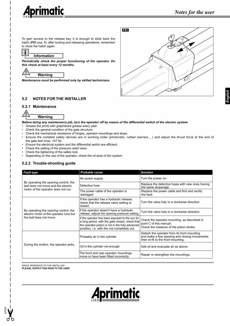
To gain access to the release key, it is enough to slide back the hatch (F01 pos. 1); after locking and releasing operations, remember to close the hatch again.
InformationPeriodically check the proper functioning of the operator. Do this check at least every 12 months.
Warning!
Maintenance must be performed only by skilled technicians.
5.2 NOTES FOR THE INSTALLER
5.2.1 Maintenance
Warning!
Before doing any maintenance job, turn the operator off by means of the differential switch of the electric system.• Grease the joints with graphitized grease every year. • Check the general condition of the gate structure. • Check the mechanical resistance of hinges, operator mountings and stops. • Ensure the installed safety devices are in working order (photocells, rubber barriers,…) and adjust the thrust force at the end of
the gate leaf (max. 147 N).• Ensure the electrical system and the differential switch are effi cient.• Check the setting of the pressure relief valve. • Check the tightening of the safety lock. • Depending on the use of the operator, check the oil level of the system.
5.2.2 Trouble-shooting guide
AP
0300
55
SPACE RESERVED TO THE INSTALLERPLEASE, SUPPLY THIS PAGE TO THE USER
R
By operating the opening control, the leaf does not move and the electric motor of the operator does not run.
No power supply. Turn the power on.
Defective fuse. Replace the defective fuses with new ones having
The power cable of the operator is Replace the power cable and find and rectify the fault.
By operating the opening control, the electric motor of the operator runs but the leaf does not move.
If the operator has a hydraulic release,check that the release valve setting is Turn the valve fully in a clockwise direction.
During the motion, the operator jerks.
Detach the operator from its front mountingProbably air in the cylinder.
Oil in the cylinder not enough Add oil and evacuate air as above.
The front and rear operator mountings Repair or strengthen the mountings.
damaged.
Fault type Probable cause Solution
closed.
move or have been fitted incorrectly
If the operator doesn't have a hydraulic release, adjiust the opening pressure setting.
If the operator has been exposed to the sun for a long period, with the gate closed, check thatthe operator piston is not in the fully advancedposition, i.e. with the rod completely out.
Turn the valve fully in a clockwise direction.
Check the operator mounting, as described inpoint C of this manual.Check the measure of the piston stroke.
and make a few opening and closing movements; then re-fit to the front mounting.
the same amperage.
F01