zs-6180af lan / gp-ib con verter - zenisu.co.jpzenisu.co.jp/product/file/m_en_zs-6180af_v1.pdf ·...
TRANSCRIPT

ZS-6180AF
LAN / GP-IB Converter
User’s Manual
Zenisu Keisoku,Inc.
Zip code: 183-0027
2-13-37, Honmachi, Fuchu, Tokyo, Japan
TEL: +81-(0)42-368-2126
FAX: +81-(0)42-364-0067

Introduction
ZS-6180AF is LAN/GP-IB converter. In order to make more effective use of ZS-6180AF, please
use this product after understanding the contents of this manual sufficiently.
In order to use this product, general knowledge about PC/AT compatible machine and
Windows(R) is necessary. If you have any questions about PC/AT compatible machine or
Windows(R), please refer to those instructions or related books etc.
The appearance and specifications of this product and items described in the instruction
manual are subject to change without notice.
Reproduction and reprinting of all matters stated by the instruction manual are
prohibited.
Company names and product names described in this instruction manual are
trademarks and registered trademarks of each company.
Please absolutely stop handling this product without fully understanding the contents of
the instruction manual.
Warranty
The warranty period of this product is the period stated in the “Letter of warranty” attached
to the product.
For defective products during the warranty period, Zenisu Keisoku,Inc repairs or replaces
defective parts for no charge. However, the product that caused a problem due to the items
listed below will be out of warranty.
Failure or damage due to inadvertent handling, accident, product misuse or abuse.
Failure or damage due to falling etc.
Failure or damage due to use of parts manufactured or sold by other than us.
Modification of product, improper repair or malfunction or damage found to be
attributable to the user’s responsibility.
Failure or damage due to other equipment connected to this product or other external
factors.
Failure or damage due to fire, earthquake, other natural disasters, pollution etc.
Replacement of consumable parts.
Adjustment, maintenance and repair in non-company designated by us.
There is no letter of warranty attached to this product.
Note) We are not responsible for any defects and damages or losses caused by disasters or third part’s actions or carelessness after the product is shipped, regardless of any circumstances.
Note) This product can not be used as parts or equipment throughout facilities such as nuclear power plants, medical equipment, railroad transportation, building management, or anything related to human lives. If it is used for these, we are not responsible for any defects and damage or loss.
Note) we are not responsible for any damage, directly or indirectly, caused by the failure of this product or its use.

Repair request If you are requesting repair, please contact to your agency or us. We will repair or replace defective product and return it. In requesting repair, please attach a letter of warranty to the product and send it with safe transportation method at your own risk. Outline ZS-6180AF is an interface converter that mediates communication between LAN and GP-IB. This device functions as a GP-IB controller by a command from a computer equipped with a LAN adapter.
[ System configuration example ]
In the above example, PC#1 and PC#2 can be GP-IB controller via ZS-6180AF respectively. The cable length
restriction of GP-IB cable is improved by using LAN cable and hub. It is also possible to perform external
control by using the VPN function. We do not support implementation of VPN function.
In- House LAN
Switching HUB
Oscilloscope Data logger Specter

To use this product safely
Warning!
Caution
Do not use the included CD-ROM absolutely except for CD-ROM
compatible players. Damage to ear may be caused by loud volume, or the
speaker may be damaged.
Fire hazard
Electric hazard
Do not disassemble / remodel this product. It may cause fire, electric shock,
or malfunction.
If it is used in an abnormal state such as smoke, odd smell or sound, it
may cause fire or electric hazard. Immediately turn off the power switch of
the main unit and connected equipment and unplug their power plug from
the outlet.
Do not use or leave in place where water and oil are scattered, in damp or
dusty places or outdoors. It may cause fire, electric hazard or failure.
Do not handle equipment with wet hands. You may get an electric shock.
If a foreign substance enters the inside of the device, turn off the computer
and the device immediately.
Do not use in places exposed to direct sunshine, extremely high temperature,
low temperature, high humidity, strong magnetized place etc. It may cause
equipment malfunction.
If it used with dew condensation, the equipment may malfunction or break
down.
Be sure to turn off the power of the computer and connected equipment
when detached the cable. If the cable is detached while turning on the power,
the device may be destroyed by overvoltage or overcurrent.
To protect the equipment against electrostatic breakdown, please do not
touch the contact part of IC or connector on board. It may be destroyed
equipment by static electricity charged on your body.
Do not adhere liquid such as water may cause electric shock or fire.

Please check the contents of the packing box
When opening the packing box, please check first that main unit and accessories are included.
If there is missing or damaged, please contact your agency immediately.
ZS-6180AF
DC input cable(Attach it as a service only if you do not purchase an optional AC adapter)
Letter of warranty
Contents of download utility ¥ …………………….……………………………. Readme.txt file is included. When there are
incompleteness in the instruction manual etc., and important contents such as specification change are included, please read first.
¥MANUAL ………………………………………. Folder containing tis instruction manual. ¥LANTRONIX …………………………………… Folder containing COM Port Redirector. ¥SAMPLE¥LANTRONIX¥VB6 ……………… Use the Telnet emulator with ComPort Redirector to
place a folder containing VB6 samples. ¥SAMPLE¥LANTRONIX¥VBNET …………… Use the Telnet emulator with ComPort Redirector
to place a folder containing VB.NET samples. ¥SAMPLE¥LANTRONIX¥VC6 ………………… Use the Telnet emulator with ComPort Redirector
to place a folder containing VC++6 samples. ¥SAMPLE¥LANTRONIX¥VCNET ……………. Use the Telnet emulator with ComPort Redirector
to place a folder containing VC++.NET samples. ¥SAMPLE¥TCPIP¥VB6 ……………………….. Use the Telnet emulator with TCP/IP to place a
folder containing VB6 samples. ¥SAMPLE¥TCPIP¥VBNET ……………………. Use the Telnet emulator with TCP/IP to place a
folder containing VB.NET samples. ¥SAMPLE¥TCPIP¥VC6 ……………………….. Use the Telnet emulator with TCP/IP to place a
folder containing VC++ samples. ¥SAMPLE¥TCPIP¥VCNET ……………………. Use the Telnet emulator with TCP/IP to place a
folder containing VC++.NET samples. ¥SAMPLE¥TCPIP¥LINUX ……………………... Use the Telnet emulator with TCP/IP to place a
folder containing samples for LINUX.

Table of contents
1. Specifications
2. Appearance
2-1. Dimensional drawing
2-2. Name of each part
3. Setting
3-1. Consider the IP address to be set for the main unit
3-2. Set the temporary IP address of the main unit to the host computer
3-3. Set IP address to ZS-6180AF
4. How to install “Com Port Redirector”
4-1. Install “Com Port Redirector” on the host computer
4-2. Set the virtual COM port of “Com Port Redirector”
5. Consider the program
6. Command description
7. Sample programs
7-1. Telnet emulator using Com Port Redirector of Lantronix
7-2. Telnet emulator using Winsock API
7-3. TCP/IP Telnet emulator running on LINUX
8. Glossary

1
1. Specifications (1) LAN
Standard: IEEE802.3 Type: 10BASE-T or 100BASE-TX(Automatic switching) Access control: CSMA/CD Modulation/Coding scheme: baseband/Manchester encoding 4B5B,NRZ Transmission speed: 10BASE-T→10Mbps, 100BASE-TX→100Mbps Transmission cable: Two pairs twist cable UTP category 5 Impedance: 100Ω Connector: RJ45-8pin modular connector(ISO8877 Std)
PIN# SIGNAL PIN# SIGNAL
1 3 5 7
TX+ RX+ N.C. N.C.
2 4 6 8
TX- N.C. RX- N.C.
Maximum segment length: 100m Wiring form: Star
Supported protocol: ARP, TCP/IP,UDP/IP,Telnet,ICMP,SNMP,DHCP,BOOTP,TFTP,AutoIP,HTTP
(2)GP-IB
Standard: IEEE 488.1-1987
Interface function:
SH1 All functions of handshake are available AH1 All functions of acceptor handshake are available
T5 All functions of talker are available L3 All functions of listener are available SR1 All functions of serial poll are available RL1 All functions of remote/local are available PP0 No parallel poll function DC1 All functions of device clear are available DT1 All functions of device trigger are available C1 System controller function is available C2 IFC transmission function is available C3 REN transmission function is available C4 SRQ response function is available C27 Interface message sending function is available
Function of control in synchronization with handshake is available
Type: piggyback amphenol 24pin cable, maximum cable length 20m, each cable length is 4m or less.
Buffer memory:
Transmission: 16 KByte
Reception: 16 KByte
Dimensions: 82mm(w) x 30mm(h) x 126mm(d)
Weight: 360g
Power supply voltage: +5VDC
Current consumption: 500mA or less
Operation temperature: 0 to +85
Humidity: 5% to 95%(No condensation)
Accessories: DC input cable(AC adapter is optional, letter of warranty
Compatible models: A computer that can access 10BASE-T or 100BASE-TX Ethernet.
OS: All OSs that can use TCP/IP or UDP/IP.

2
2. Appearance 2-1.Dimensional drawing
82.5 126
30
30
前面
背面
右側面
Front View Right side View
Back View

3
2-2. Name of each parts
① ② ③ ④ ⑤ ⑥ ⑦
前面① ゴム足② データ送信表示灯③ データ受信表示灯④ トーカ表示灯⑤ リスナ表示灯⑥ 作動中表示灯⑦ GP-IBコネクタ
①⑦ ⑧ ⑨ ⑩
背面① ゴム足⑦ GP-IBコネクタ⑧ LANコネクタ⑨ 電源スイッチ⑩ 電源供給コネクタ
① ⑦
右側面① ゴム足⑦ GP-IBコネクタ
1 Rubber foot It is attached as standard. 2 Data transmission indicator light It lights up when this product transmits data to the host computer. 3 Data reception indicator light It lights up when this product receives data from the host computer. 4 Talker indicator light It lights up when this product is in talker mode of GP-IB device. 5 Listener indicator light It lights up when this product is in listener mode of GP-IB device. 6 Power light It lights up when +5VCD is supplied to the power supply connector and the power switch is turned on. 7 GP-IB connector This is for connecting the GP-IB cable. 8 LAN connector Connector of RJ-45 to connect the LAN cable for linking with the host computer. Be sure to connect with
a cross-cable if not via the hub, straight-cable if via the hub. 9 Power switch It is a slide switch that puts the power supply into the circuit. ⑩ Power supply connector For +5VDC AC adapter.

4
3. Setting Set the IP address as follow.
Consider the IP address to be set for the main unit.
↓
Set the temporary IP address of the main unit to the host computer used to set the IP address to the main unit.
Note) It is set to the host computer itself, it is not yet set to the main unit.
↓
Set IP address to ZS-6180AF.
3-1. Consider the IP address to be set for the main unit. ① Run the command prompt(MSDOS prompt) on the host computer and execute the ipconfig command.
Example) ipconfig
② As a result of the ipconfig command, you can see the value of your network part.
In this example, the network part is 192.168.1. The host part numbers unused numbers. To determine
the IP address of the ZS-6180AF, the network part of the IP address is determined as above. For the host part, please ask the network administrator to allocate the empty number of the host part. The combined network part and host part is the IP address of ZS-6180AF.
IP Address
Subnet Mask
Network part Host part

5
3-2. Set the temporary IP address of the main unit to the host computer. 1. Prepare the warranty certificate of the ZS-6180AF, refer to the MAC address affixed to the letter of
warranty. 2. Connect the ZS-6180 to the LAN. 3. Connect the Ac adapter to a 100V outlet and connect the AC adapter to the ZS-6180AF. Then turn on
the power switch of ZS-6180AF. Note) In order to be following explanation, the IP address determined above will be “192.168.1.33” and the
MAC address written in the letter of warranty will be “00-20-4A-80-29-BC”. However, be sure to change the IP address and MAC address to the value you set yourself.
Run the command prompt (MSDOS prompt) on the host computer and set the temporary IP address of
ZS-6180AF. The temporary address is set to the host computer, but not set to the ZS-6180AF.
At the command prompt, enter the following command and execute it.
Example) arp -s 192.168.1.33 00-20-4a-80-29-bc

6
3-3. Set IP address to ZS-6180AF ① At the command prompt, enter the following command and execute it.
Example) telnet 192.168.1.33 1 An error will be displayed, but please ignore this message.
② At the command prompt, enter the following command prompt and execute it.
Example) telnet 192.168.1.33 9999
7
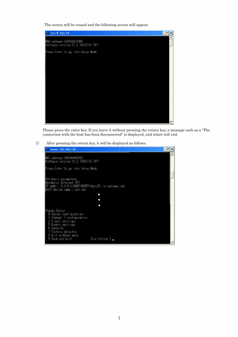
The screen will be erased and the following screen will appear.
Please press the enter key. If you leave it without pressing the return key, a message such as a “The connection with the host has been disconnected” is displayed, and telnet will end.
③ After pressing the return key, it will be displayed as follows.

8
④ As you are being asked “Your choice?”, please enter “0”. Then you will be prompted to enter the IP address, so enter the IP address of ZS-6180AF which was decided by “3-1. Consider IP address to be set for the main unit”. In this screen image shown below, please enter it in the place indicated by white underline.
⑤ As you are asked “Your choice?” again, please enter “9” at this time and save the setting value to the ZS-6180AF.
Completes the setting of the IP address to the ZS-6180AF.

9
4. How to install “COM Port Redirector” This section explains how to install “COM Port Redirector” made by Rantronix.Inc, which can be used without being conscious of TCP/IP or UDP/IP. This “COM Port Redirector” provides a virtual COM port for user application programs. By performing serial communication with this virtual COM port, the user application program can communicate with other devices connected via Ethernet by “COM Port Redirector” operates on Windows®XP or later. For details, please see the explanation of “COM Port Redirector” as below. You can also download from the following website. There are Network installation version and Standalone version, so please choose according to your operating environment. http://www.lantronix.com/device-networking/utilities-tools/com-port-redirector.html
Note) If you are writing TCP/IP or UDP/IP user application program, skip this section.
The procedure is as follows.
Install “COM Port Redirector” on the host computer.
↓
Set the virtual COM port of “COM Port Redirector”.
4-1. Install “Com Port Redirector” on the host computer.
An example with Windows 7 64bit version as below. The details may be different depending on the
environment.
① Execute the download setup_cpr_x86x64cd_4.3.0.3.exe (standalone version). When executed, the following screen will appear. It is also abbreviated as CPR.
Click “Install” button.
② It will see the following screen.
Click “NEXT” button.
10
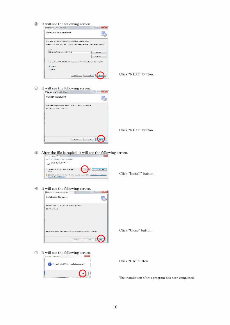
③ It will see the following screen.
Click “NEXT” button.
④ It will see the following screen.
Click “NEXT” button.
⑤ After the file is copied, it will see the following screen.
Click “Install” button.
⑥ It will see the following screen.
Click “Close” button.
⑦ It will see the following screen.
Click “OK” button.
The installation of this program has been completed.

11
4-2. Set the virtual COM port of “COM Port Redirector”.
① From the start menu, select [Program]>>[Lantronix]>>[CPR X.X]>>[CPR Manager] and start it.
Then the following “CPR Manager” screen will be displayed. The state of the COM port depends on your operating environment.
Click “Add/Remove” on the left side of the screen to display the “Com Ports” screen.
② It will see the following screen.
On the “Com Ports” screen on the left, check the COM port number to be set as the virtual COM port. An example of setting to “Com 10” is explained as here. Click the “OK” button to return to the “CPR Manager” screen.
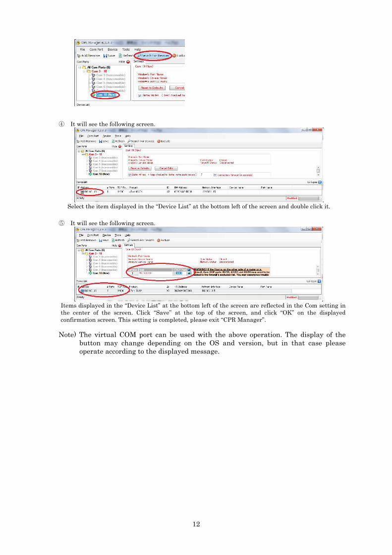
③ It will see the following screen.
Select the port set in ② in “COM Ports” on the left side of the screen and click “Search For Devices”.
12
④ It will see the following screen.
Select the item displayed in the “Device List” at the bottom left of the screen and double click it.
⑤ It will see the following screen.
Items displayed in the “Device List” at the bottom left of the screen are reflected in the Com setting in the center of the screen. Click “Save” at the top of the screen, and click “OK” on the displayed confirmation screen. This setting is completed, please exit “CPR Manager”.
Note) The virtual COM port can be used with the above operation. The display of the button may change depending on the OS and version, but in that case please operate according to the displayed message.

13
5. Consider the program The communication program with ZS-6180AF is a program in which the host computer is the client and the ZS-6180AF is the server. At this time, the client side program consists of three blocks that are “Establish link with ZS-6180AF”, “Communicate for ZS-6180AF and GP-IB control” and “Cancel link with ZS-6180AF”.
Note) The flow chart on the session is shown on the right side.
1 Establish link with ZS-6180AF.
1. Initialize Winsock. 2. Create socket. 3. Specify the IP address and port number of
ZS-6180AF and perform connection processing with ZS-6180AF.
2 Communicate for ZS-6180AF and GP-IB control. Control the external GP-IB device using the GP-IB command of ZS-6180AF. At this time, there are four type of access procedures by the GP-IB command, which are described as Case 1 to Case 4. It will be described in detail later.
3 Cancel link with ZS-6180AF. Discard the socket and end the communication. A : Connect request B : Connect response C : Command transmission D : Command response E : Command transmission F : Data transmission G : Command response H : Command transmission I : Data reception J : SRQ reception K : Cancel request L : Cancel response
Host computer ZS-6180AF
A 1
2
3
Ca
se 1
Ca
se 2
Ca
se 3
Ca
se 4
B
C
D
E
F
G
H
I
J
K
L

14
Access details of GP-IB communication control The command to ZS-6180AF consists of 3 to 4 characters command name using ASCII code followed by
parameter (character string). Command include control commands, data output command, and data request commands. Upon receipt of a command from the host computer, the ZS-6180AF performs control corresponding to that command and sends a response message corresponding to the command to the host computer. The host computer sends the command to the ZS-6180AF, and receiving the response message from the ZS-6180AF, send the next command.
There are the following types of response messages after command execution.
1.END CR LF A control command without data to be returned to the host computer or a data output command. (case1, 2)
2.XXX・・・XX CR LF Data request command etc. that returns data to the host computer. (case 3).
3.F-ERR CR LF When there is a format error (case 1, 2, 3). 4.G-ERR CR LF When there is a timeout error (case 1, 2, 3). 5.O-ERR CR LF When there is a overflow error (case 1, 2, 3). 6.P-ERR CR LF When there is a parameter error (case 1, 2, 3). 7.R-ERR CR LF When there is a internal error (case1, 2, 3).
8.SRQ CR LF When SRQ occurs, SRQ it is sent from the ZS-6180AF without sending a command
from the host computer (case 4).
When a person making TCP/IP programming wants to change the port number.
A person who creates TCP/IP applications without using COM Port Redirector will indicate how to change the port number of ZS-6180AF.
① Please start the web browser (Internet Explorer, Netscape Navigator, etc.). Then enter the IP address of ZS-6180AF set in the URL address. Example) http://192.168.1.33 The menu
opens as shown on the right.
② Make sure that “Port Properties” indicated as A is selected. Please select if not selected. If it is selected, the color of button will turn to orange.
③ The value of “Local Port” indicated as B is the
port number. The initial setting is 14000. Please set the port number you want to change. To restore the value, set it to 14000 again.
④ The setting is completed by clicking “Update
Setting” indicated as C.
Note) Since it may not operate properly, please do not change other items.
A
B
C

15
6. Command description
How to send commands Commands from the host PC are sent in the order of "command", “CR”, “LF”, “CR” is 0x0d, “LF” is 0x0a. Commands can be sent consecutively, separated by “ : ”colon. [command] : [command] : [command] …….. [command] : [command] [CR] [LF]
This is called multi-command. The multi-command function is performed with commands MCE and MDC. Upon receiving the multi-command, ZS-6180AF sequentially executes the command, and after completing execution of all commands, sends a response message to the host computer. This response message belongs to the latest command executed. Therefore, when using any of the seven commands (INP, INPB, IND, INDB, INC, INCB, RDS) that return data in response message as multi-command, be sure to put it at the end of the command sequence. If an error occurs during multi-command execution, the command execution is terminated at that point, and an error response message is returned to the host computer.
Command format Command format is as bellow. [ Command code ] _ [ Address or Parameter ] ; [ (Data) ] (Space) (Semicolon)
If there are multiple address or parameters, separate them with a comma (,). The address is a decimal
two digits code, the parameter and the data have two decimal digits and two hexadecimal digits. Some commands do not require semicolon (; ) afterwards.
Internal buffer memory The ZS-6180AF executes the command after storing the command, data and delimiter sent from the host
computer in the internal receive buffer memory. The size of the internal receive buffer memory, including the delimiter, is 16 Kbytes. ZS-6180AF returns O-ERR to the host computer if amount of data sent from the host computer 16 Kbytes or more. When data is received from the GP-IB device, the data is stored in the internal transmission buffer memory. The size of internal transmission buffer memory is 16 Kbytes. If the data received from the GP-IB device exceeds 16 Kbytes, GP-IB data is received but discarded without being stored in the internal transmission buffer memory.
Transmission buffer memory 16 Kbytes
Received buffer memory 16 Kbytes
LAN interface GP-IB interface
Host computer
GP-IB bus ZS-6180AF

16
GP-IB address Execute GP-IB address setting command of ZS-6180AF. This command name is SGA. For details, refer to
the SGA in the command table.
SRQ ZS-6180AF has SRQE mode and SRQD Mode. In the SRQE mode, the host computer is notified of the
occurrence of the GP-IB SRQ. SRQD mode does not notify the occurrence of SRQ. ① SRQE mode
This command enables the interrupt processing function. When SRQ occurs, SRQ message is sent to the host computer. However, if SRQ occurs during command execution, ZS-6180AF sends SRQ message to the host computer after sending a response message
② SRQD mode
This command disables the interrupt processing function. Even if SRQ occurs, it will not be notified to the host computer. After turning on the power switch, this mode is set.
Error message
Error code Contents F-ERR
(Format Error) There is an error in command format. The number of specified address exceeds 31. Amount of received commands and transmitted data is 16 Kbytes or more. The number of data exceeds 5000 with some commands. The command does not put at the end of transmission data when using multi-command.
G-ERR (Timeout Error)
Amount time of the GP-IB handshake exceed the value set with the TOE command. When ZS-6180AF is in talker mode, it tried to send a message to the device even though no listener device exists.
O-ERR (Overflow Error)
There are more than 16 Kbytes of command or multi-command including the delimiter send from the host computer.
P-ERR (Parameter Error)
The address or parameter value of each command is out of range. Binary data is a value other than 0 to F.
R-ERR (Internal Error)
Internal error occurred with ZS-6180AF.
ZS-6180AF sends UNT(0x5f) and UNL(0x3f) to the GP-IB bus when G-ERR occurs, and stops
communication. Please re-set the talker and listener. ZS-6180AF will not accept any subsequent commands when R-ERR occurs. Please turn off the power,
then turn it on again and restart. Command processing is suspended when an error occurs other than R-ERR.
Initial setting
1. GP-IB address: 0 2. Delimiter of GP-IB device message: CR, LF, EOI 3. GP-IB timeout function: 25.5 seconds 4. SRQ mode setting: SRQD mode 5. Multi-command mode: Invalid
After turning on the power, ZS-6180AF automatically executes IFC and makes REN true and put it in
remote state. Then, it waits for a command from the host computer.

17
Command table
Command Function REM Set the REN signal to TRUE and put all devices in remote state. IFC Initialize interface function of all devices. DCL Initialize all devices. SDC Initialize specified equipment. GTL Set the REN signal to false and put all the devices in local state.
Make the specified device in local state. LLO Set all devices to local state prohibited. GET Send a trigger to a specified device. CMD Send an interface message. TAD Set a specified device as a talker. LAD Set a specified device as a listener. DAT Send a device message as ASCII character string data.
DATB Send a device message as a binary data. OUT Send a device message with listener device specification.
OUTB DATB command with listener device specification. IND Receive a device message as ASCII character string data.
INDB Receive a device message as a binary data. INP IND command with talker device specification.
INPB INDB command with talker device specification. INC INP command with received byte count setting function.
INCB INPB command with received byte count setting function. RDS Execute a serial poll. DLM Set a delimiter of device message. TOE Set a timeout of GP-IB handshake.
SRQE Enable SRQ mode. SRQD Disable SRQ mode. SGA Set a GP-IP address of ZS-6180AF. MCE Enable multi-command. MCD Disable multi-command. RST Reset ZS-6180AF.

18
Description of each commands
REM
Set REM signal to TRUE
Format
REM Set REN signal to true on the GP-IB bus.
【Argument】
None
【Note】
After turning on the power, ZS-6180AF executes IFC and set the REN signal to true.
IFC
Initialize interface function of all devices
Format
IFC It outputs a true pulse to the IFC signal on the GP-IB bus and initializes the GP-IB interface
function of all the devices. The pulse width is about 100 µs.
【Argument】
None
【Note】
After turning power on, ZS-6180AF executes IFC.
DCL
Initialize all devices
Format
DCL Send the DCL message to all devices on the GP-IB bus. Request initialization for all devices
with DC function.
【Argument】
None

19
SDC
Initialize specified equipment
Format
SDC [addresses] SDC message is sent to a specified device on the GP-IB bus. SDC message is used to the
device specified as a listener.
【Argument】
Addresses: It is a device address of two decimal digits separated by 1 to 31 commas. Device
address range is 00 to 30.
【Example】
SDC 00,01,30
Initialize the device with device address 0, 1, 30.
GTL
Set the device to the local state
Format 1
GTL Set the REN signal to false and put all devices in local state. Request the transition to the
local state for all devices with RL function.
【Argument】
None
Format 2
GTL [addresses] GTL message is sent to a specified device on the GP-IB bus. Request the transition to the local
state to specified device with RL function. GTL message is used to the device specified as a
listener.
【Argument】
Addresses: It is a device address of two decimal digits separated by 1 to 31 commas. Device
address range is 00 to 30.
【Note】
If GP-IB address of ZS-6180AF is specified as GTL address, operation can not be guaranteed.
【Example】
GTL 00,01,30
Set the device with device address 0, 1, 30 to local state.

20
LLO
Set a device to local state prohibited
Format
LLO Send an LLO message to all the devices on the GP-IB bus. The LLO message requests that all
device with RL function be prohibited from transitioning to the local state.
【Argument】
None
GET
Send a trigger to a specified device
Format
GET [addresses] Send a GET message that issues a trigger to a specified device on the GP-IB bus. GET
message is used to the device specified as a listener.
【Argument】
Addresses: It is a device address of two decimal digits separated by 1 to 31 commas. Device
address range is 00 to 30.
【Example】
GET 00,01,30
It issues a trigger to the device with device address 0, 1, 30.
21
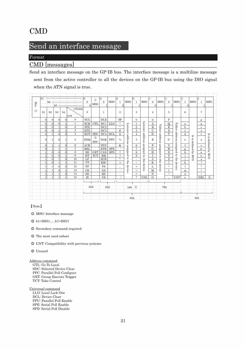
CMD
Send an interface message
Format
CMD [messages] Send an interface message on the GP-IB bus. The interface message is a multiline message
sent from the active controller to all the devices on the GP-IB bus using the DIO signal
when the ATN signal is true.
b7 0 0 0 0 1 1 1 1b6 0 0 1 1 0 0 1 1
b5 0 1 0 1 0 1 0 1
0 0 0 0 NUL DLE SP 0 @ P p
0 0 0 1 SCH GTL DC1 LLO ! 1 A Q a q0 0 1 0 STX DC2 " 2 B R b r0 0 1 1 ETX DC3 # 3 C S c s0 1 0 0 EOT SDC DC4 DCL $ 4 D T d t
0 1 0 1 ENQ③
PPCNAK PPU % 5 E U e u
0 1 1 0 ACK SYN & 6 F V f v0 1 1 1 BEL ETB SPE k' 7 G W g w1 0 0 0 BS GET CAN SPD ( 8 H X h x1 0 0 1 HT TCT EM ) 9 I Y i y1 0 1 0 LF SUB * : J Z j z1 0 1 1 VT ESC + ; K [ k +
1 1 0 0 FF FS , < L 〵 l 〵1 1 0 1 CR GS - = M ] m 1 1 1 0 SO RS . > N ^ n ~1 1 1 1 SI US k/ ? UNL O _ UNT o DEL ⑥
91011
Listen
er add
ress assigned
to the d
evice
3
MSG
4
MSG
15
4
5
6
0
3
column
row
0
12
12
1314
78
MSG
6
Bits
②
b1 b2 b3 b4
MSG①
MSGMSG
1 2 7
MSG MSG
It is defin
ed by B
CG
It is defin
ed by
BC
G
5
Talk
er ad
dress assign
ed
to the d
evice
Talk
er add
ress assigned
to the d
evice
Listen
er add
ress assigned
to the d
evice
ACG UCG TAGLAG ④
PCG SCG
【Note】
1 MSG: Interface massage
2 b1=DIO1…..b7=DIO7
3 Secondary command required
4 The most used subset
5 UNT: Compatibility with previous systems
6 Unused
Address command
GTL: Go To Local SDC: Selected Device Clear PPC: Parallel Poll Configure GET: Group Execute Trigger TCT: Take Control
Universal command
LLO: Local Lock-Out DCL: Device Clear PPU: Parallel Poll Enable SPE: Serial Poll Enable SPD: Serial Poll Disable

22
【Argument】
Messages: A hexadecimal two-digit interface message represented by an uppercase ASCII
character separated by 1 to 31 commas.
【Example】
CMD 3F,20,21,43
Send 3F(UNL), 20(LA0), 21(LA1), 43(TA3).
TAD
Set a specified device as a talker
Format
TAD [address] Set a specified device as a talker on the GP-IB bus.
【Argument】
Address: Device address of two decimal digits, device address range is 00 to 30.
【Example】
TAD 01
Set the device with device address 1 as a talker.
LAD
Set a specified device as a listener
Format
LAD [addresses] Set a specified device as a listener on the GP-IB bus.
【Argument】
Addresses: It is a device address of two decimal digits separated by 1 to 31 commas. Device
address range is 00 to 30.
【Example】
LAD 00,01,30
Set the device with device address 0, 1, 30 as a listener.

22
DAT
Send a device message as ASCII character string data
Format
DAT [ascii-chars] Send a device message on the GP-IB bus. Use the ASCII character as the argument of the
message.
【Argument】
ascii-chars: ASCII character string from 0x21 to 0x7e. the ASCII character string must be
less than 16384 characters in length including the command delimiter.
【Note】
When using the multi-command function, the colon “ : ” character can not be used. When
using the colon “ : ” character, please disable the multi-command function. In this command,
delimiters are not output on the GP-IB bus at the end of the character string.
【Example】
DAT ABCD1234
ABCD1234 is sent as a device message on the GP-IB bus.
DATB
Send a device message as a binary data
Format
DATB [HByte-chars] Send a device message on the GP-IB bus. Use an argument with a byte string as a
hexadecimal ASCII character string.
【Argument】
HByte-chars: Two hexadecimal digit byte data represented by uppercase ASCII characters
separated by 1 to 5000 commas.
【Note】
In this command, delimiters are not output on the GP-IB bus at the end of the character
string.
【Example】
DATB 05, F0, 0A, A0
0x05, 0xf0, 0x0a, 0xa0 are sequentially sent as device messages on the GP-IB bus.

22
OUT
Send device message with listener device specification Format
OUT [listener-addr];[ascii-chars] Send the device message to the specified one listener device on the GP-IB bus. Use the ASCII
character as the argument of the message. Add the delimiter set by the DLM command to
the end of the message and send it on the GP-IB bus.
【Argument】
listener-addr: It is a listener device address of two decimal digits, address range is 00 to 30.
ascii-chars: It is ASCII character string from 0x21 to 0x7e. The ASCII character string must
be less than 16384 characters in length including the command delimiter.
【Note】
When using the multi-command function, you can not used the colon ” : “ character string.
Please disable the multi-command function when using the colon “ : ”.
【Example】
OUT 01;1234WXYZ
Set device address 1 as a listener. Send device message “1234WXYZ” with the delimiter
which is set by the DLM command at the end of the device message to the GP-IB bus.
OUTB
Send device message with listener device specification Format
OUTB [listener-addr];[HByte-chars] Send the device message to the specified one listener device on the GP-IB bus. Use byte string
as a hexadecimal ASCII character string, as an argument of the message. The delimiter is
always EOI and sends to the last byte of the message.
【Argument】
listener-addr: It is a listener device address of two decimal digits, address range is 00 to 30.
HByte-chars: Hexadecimal two digits byte data that is represented by uppercase ASCII
characters and separated by 1 to 5000 commas.
【Note】
The setting of DLM command is ignored, and the delimiter is always EOI only.
【Example】
OUTB 01;50,F0,0A,A0
Set device address 1 as a listener. As a device message “0x50, 0xf0, 0x0a, 0xa0” are
sequentially sent on the GP-IB bus, and EOI of the delimiter is sent together with the
last byte 0xa0.

22
IND
Receive a device message as ASCII character string Format
IND It receives device messages from devices specified as talkers on the GP-IB bus. Received
message are imported as ASCII characters, and reception is terminated by receiving the
delimiter set by DLM command. ZS-6180AF is possible to receive device messages up to 16
Kbytes from the talker device, but received device message exceeding 16 Kbytes are
discarded.
This command is used to repeated device messages from devices already specified as talkers.
【Argument】
None
【Return value】
ascii-chars: It is ASCII character string from 0x00 to 0xff. However, be sure to confirm that
the talker equipment sends out only the printable code.
【Note】
When using the multi-command function, use this command at the end. If an error occurs in
the return value, the error information is preferentially returns.
【Example】
IND
It receives the device message that is sent ASCII character string and delimiter on the
GP-IB bus from the equipment specified as a talker, and extracts the ASCII character
string.
INDB
Receive a device message as a binary data Format
INDB It receives device messages from devices specified as talkers on the GP-IB bus. After setting
the delimiter to EOI with DLM command, the received message is imported as a hexadecimal
ASCII string of bytes, and reception is terminated by receiving the EOI of the delimiter.
ZS-6180AF is possible to receive device messages up to 16 Kbytes from the talker device, but
received device message exceeding 16 Kbytes are discarded.
This command is used to repeated device messages from devices already specified as talkers.
【Argument】
None

22
【Return value】
HByte-chars: Hexadecimal two digits represented by ASCII characters up to 16 Kbytes.
【Note】
When using the multi-command function, use this command at the end. If an error occurs in
the return value, the error information is preferentially returns.
【Example】
INDB
It receives the device message that is sent ASCII character string and delimiter on the
GP-IB bus from the equipment specified as a talker, and extracts the ASCII character
string.
INP
Receive device message with talker device specification Format
INP [talker-addr] It receives device messages from devices specified as talkers on the GP-IB bus. Received
messages are imported as ASCII characters, and reception is terminated by receiving the
delimiter set by the DLM command. ZS-6180AF is possible to receive device messages up to
16 Kbytes from the talker device, but received device message exceeding 16 Kbytes are
discarded.
【Argument】
talker-addr: It is a talker device address of two decimal digits, address range is 00 to 30.
【Return value】
ascii-chars: It is ASCII character string from 0x00 to 0xff. However, be sure to confirm that
the talker equipment sends out only the printable code.
【Note】
When using the multi-command function, use this command at the end. If an error occurs in
the return value, the error information is preferentially returns.
【Example】
INP 01
Set device address 1 as a talker, receive ASCII character string, delimiter sent as a device
message from talker on GP-IB bus, and extract ASCII character string.

22
INPB
Receive device message with talker device specification Format
INPB [talker-addr] It receives device messages from devices specified as talkers on the GP-IB bus. After setting
the delimiter to EOI with DLM command, the received message is imported as a
hexadecimal ASCII string of bytes, and reception is terminated by receiving the EOI of the
delimiter. ZS-6180AF is possible to receive device messages up to 16 Kbytes from the talker
device, but received device message exceeding 16 Kbytes are discarded.
【Argument】
talker-addr: It is a talker device address of two decimal digits, address range is 00 to 30.
【Return value】
HByte-chars: Hexadecimal two digits represented by ASCII characters up to 16 Kbytes.
【Note】
When using the multi-command function, use this command at the end. If an error occurs in
the return value, the error information is preferentially returns.
【Example】
INPB 01
Set device address 1 as a talker, receive ASCII character string, delimiter sent as a device
message from talker on GP-IB bus, and extract ASCII character string.
INC
Receive specified device message of the number of bytes with talker device specification Format
INC [talker-addr];[Byte-chars] Specify one talker device on GP-IB bus and receive device message. Received messages are
imported as ASCII characters, and reception is terminated by receiving the specified
number of bytes. The delimiter setting is invalid with this command, so please do not
output EOI. ZS-6180AF is possible to receive device messages up to 16 Kbytes from the
talker device, but received device message exceeding 16 Kbytes are discarded.
【Argument】
talker-addr: It is a talker device address of two decimal digits, address range is 00 to 30.
Byte-chars: it is decimal two digits of specified number of bytes, range is 01 to 99.
【Return Value】
ascii-chars: It is ASCII character string from 0x00 to 0xff. However, be sure to confirm that
the talker equipment sends out only the printable code.
22
【Note】
When using the multi-command function, use this command at the end. If an error occurs in
the return value, the error information is preferentially returns.
【Example】
INC 01;04
Set device address 1 as a talker, receive four bytes of ASCII character string sent as a
device message from talker on GP-IB bus, and extract ASCII character string.
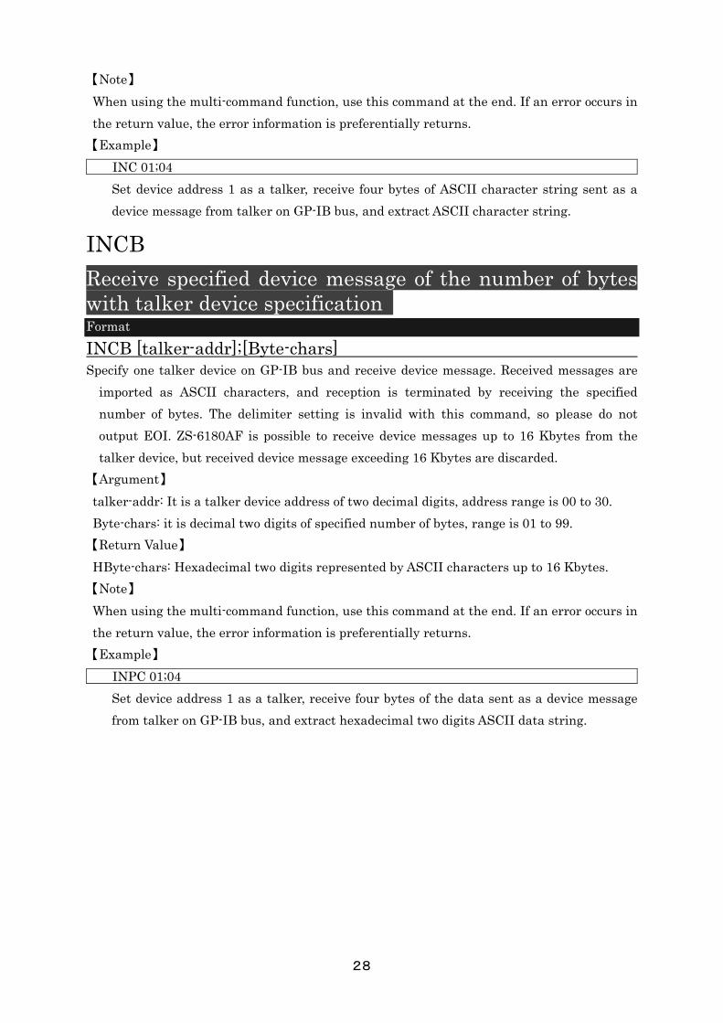
INCB
Receive specified device message of the number of bytes with talker device specification Format
INCB [talker-addr];[Byte-chars] Specify one talker device on GP-IB bus and receive device message. Received messages are
imported as ASCII characters, and reception is terminated by receiving the specified
number of bytes. The delimiter setting is invalid with this command, so please do not
output EOI. ZS-6180AF is possible to receive device messages up to 16 Kbytes from the
talker device, but received device message exceeding 16 Kbytes are discarded.
【Argument】
talker-addr: It is a talker device address of two decimal digits, address range is 00 to 30.
Byte-chars: it is decimal two digits of specified number of bytes, range is 01 to 99.
【Return Value】
HByte-chars: Hexadecimal two digits represented by ASCII characters up to 16 Kbytes.
【Note】
When using the multi-command function, use this command at the end. If an error occurs in
the return value, the error information is preferentially returns.
【Example】
INPC 01;04
Set device address 1 as a talker, receive four bytes of the data sent as a device message
from talker on GP-IB bus, and extract hexadecimal two digits ASCII data string.
22
RDS
Execute a serial poll
Format
RDS [addresses] Execute a serial poll for a specific device on the GP-IB bus. After execution, returns the device
address and status byte. The host computer judges which device issued the SRQ.
【Argument】
Addresses: Device address of decimal two digits separated by 1 to 31 commas, device address
range is 00 to 30.
【Return Value】
adr-stb: The device address of the specified device and the status byte are returned
hexadecimal two digits. If there are two or more specified device addresses, the return values
of those devices are also added. In case of the status byte with delimiter is 40 or more in
hexadecimal, it indicates that the device is generating SRQ.
【Example】
RDS 00,01,30
Serial poll is executed on the device with device address 0, 1, 30. If the return value is
returned as below, the device with device address 0 is generating SRQ.
004001001E00
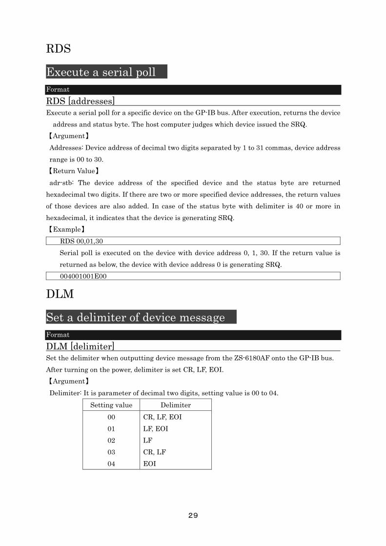
DLM
Set a delimiter of device message
Format
DLM [delimiter] Set the delimiter when outputting device message from the ZS-6180AF onto the GP-IB bus.
After turning on the power, delimiter is set CR, LF, EOI.
【Argument】
Delimiter: It is parameter of decimal two digits, setting value is 00 to 04.
Setting value Delimiter
00
01
02
03
04
CR, LF, EOI
LF, EOI
LF
CR, LF
EOI

23
【Example】
DLM 01
Set the delimiter LF, EOI
TOE
Set a timeout of GP-IB handshake
Format
TOE [time] Set the time from GP-IB handshake stop to restart. When handshake stop period exceeds
setting value, G-ERR error message is sent to the host computer. ZS-6180Af does not
execute the recovery of the handshake stop. The setting time is value multiplied by 100 ms
to the value expressed in hexadecimal two digits. After turning on the power, it is set to FF
and timeout is set to 25.5 seconds.
【Argument】
time: It is parameter of hexadecimal two digits, setting value is 00 to FF.
Setting value Setting time
00
01
02
:
:
FF
Invalid (Send P-ERR)
100 ms
200 ms
:
:
25.5 sec
【Example】
TOE 02
Set the time to 200 ms until G-ERR is sent.
SRQE
Enable SRQE mode
Format
SRQE When SRQ occurs on the GP-IB system, set to send SRQ message to the host computer.
If SRQ occurs while another command is being executed, SRQ message is sent after completed
of the command execution.
【Argument】
None

23
【Note】
If SRQ has occurred on the GP-IB system before this command is executed, ZS-6180AF is not
possible to detect that SRQ. ZS-6180Af is possible to detect SRQ when SRQE mode is set and
it is in SRQE mode. Therefore, in order to forcibly release the SRQ, execute the RDS
command for all the connected devices.
【Sending message】
SRQ CR LF
【Example】
SRQE
When SRQ occurs on the GP-IB system, set to send SRQ message to the host computer.
SRQD
Disable SRQ mode
Format
SRQD When SRQ occurs on the GP-IB system, set not to send SRQ message to the host computer.
After turning on the power, this mode is set.
【Argument】
None
【Example】
SRQD
When SRQ occurs on the GP-IB system, set not to send SRQ message to the host
computer.
SGA
Set the GP-IB address of ZS-6180AF
Format
SGA [address] Set the GP-IB address of ZS-6180Af. After tuning on the power, GP-IB address is set 00.
【Argument】
Address: Device address of decimal two digits, device address rang is 00 to 30.
【Example】
SGA 06
Set the GP-IB address of ZS-6180AF to 6.

22
MCE
Enable multi-command
Format
MCE Set the mode to enable multi-command. After turning on the power, ZS-6180Af is set to
disable multi-command.
【Argument】
None
【Example】
MCE
Set the mode to enable multi-command.
MCD
Disable multi-command
Format
MCD Set the mode to disable multi-command. After turning on the power, ZS-6180Af is set to
disable multi-command.
【Argument】
None
【Example】
MCD
Set the mode to disable multi-command.
RST
Reset ZS-6180AF
Format
RST It is initializes ZS-6180AF. If it is not R-ERR, ZS-6180Af is possible to be initialized by this
command at any time from the host computer.
【Argument】
None
【Example】
RST
It is initializes ZS-6180AF.

22
7. Sample program It explains the sample program that is possible to be downloaded from our website. This program is created with Microsoft®VisualBasic 6, VisualBasic.NET, Visual C++6, VisualBasic C++.NET and gcc for Linux. The function of this program is a basic Telnet emulator. In Visual basic and Visual C++, two types of programs are prepared for each version. On Linux, prepared TCP/IP Telnet emulator. 1 Telnet emulator using Lantronix’s ComPort Redirector. 2 TCP/IP Telnet emulator using Winsock API or Win32 API. 1. Telnet emulator using Lantronix’s ComPort Redirector.
Description of each function
① Communication window (Text Box) This window displays the communication contents between the host computer and ZS-6180AF. It does not correspond to the latest 25 rows binary. ② Command sending window (Text Box)
Enter the command that the host computer sends to ZS-6180AF. ③ Closed button
Press this button to end the program. ④ ComPort number window (Text Box)
Enter the ComPort number set by ComPortRedirector. ⑤ Delimiter setting box (combo box)
Delimiters “CR”, “LF”, “CR, LF” can be selected, but always select “CR, LF” ⑥ Connect/Disconnect button (command button)
Set the ComPort to Open/Closed ⑦ Send button (command button)
Send the command entered in window2 . Note) Communication protocol is 19200bps, no parity, stop bit 1, character bit length 8. The communication
speed can be up to 230.4Kbps. You can set it freely in this range.
22
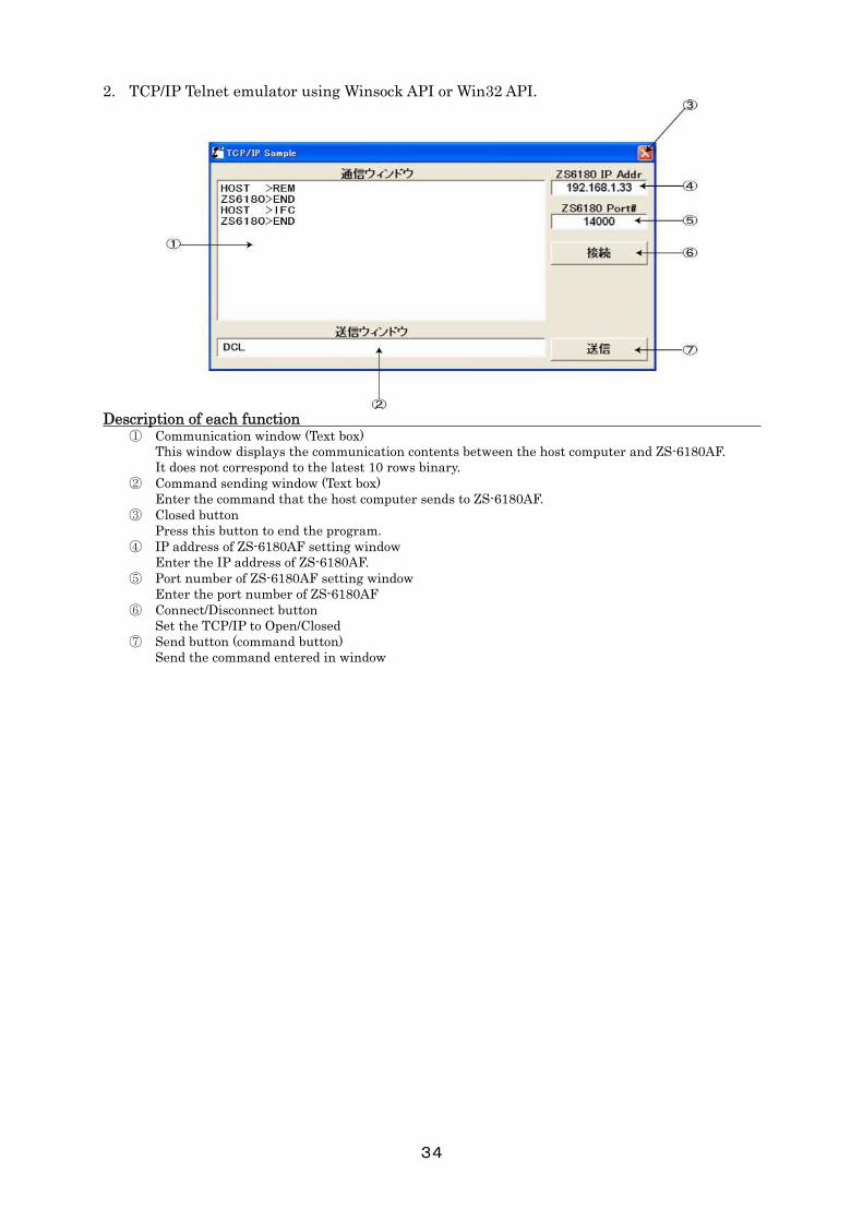
2. TCP/IP Telnet emulator using Winsock API or Win32 API.
Description of each function
① Communication window (Text box) This window displays the communication contents between the host computer and ZS-6180AF. It does not correspond to the latest 10 rows binary. ② Command sending window (Text box)
Enter the command that the host computer sends to ZS-6180AF. ③ Closed button
Press this button to end the program. ④ IP address of ZS-6180AF setting window
Enter the IP address of ZS-6180AF. ⑤ Port number of ZS-6180AF setting window
Enter the port number of ZS-6180AF ⑥ Connect/Disconnect button
Set the TCP/IP to Open/Closed ⑦ Send button (command button)
Send the command entered in window
22
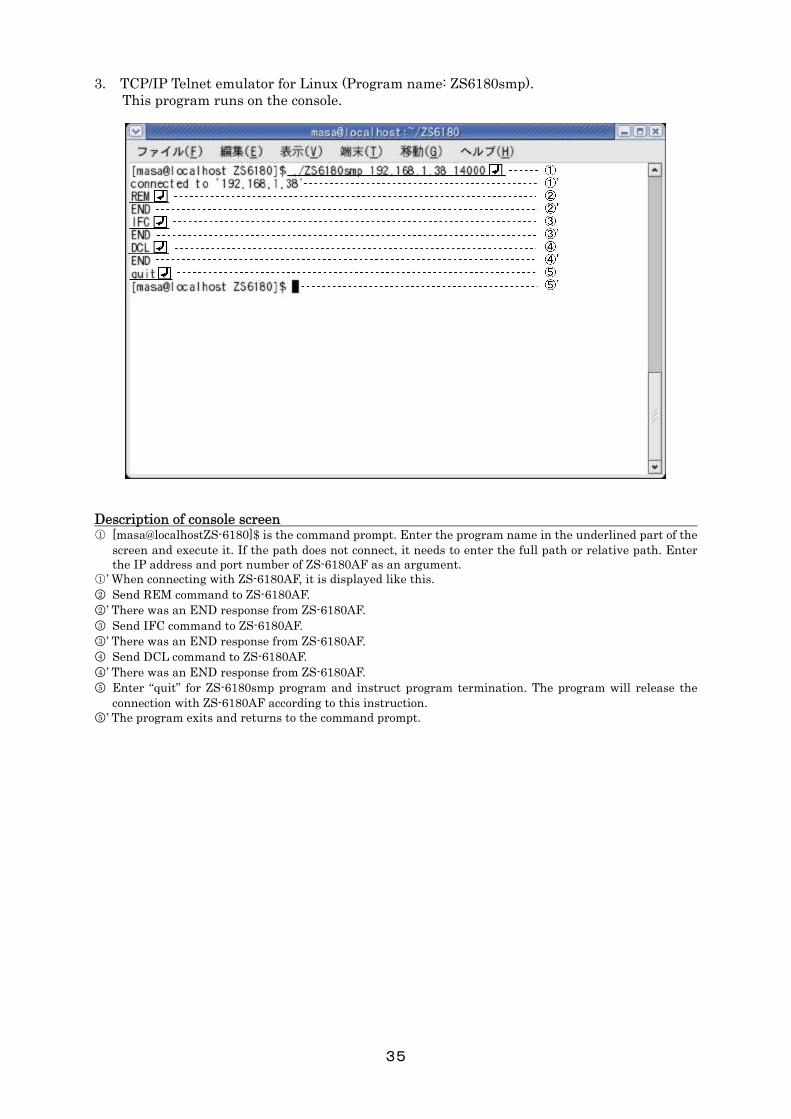
3. TCP/IP Telnet emulator for Linux (Program name: ZS6180smp). This program runs on the console.
Description of console screen 1 [masa@localhostZS-6180]$ is the command prompt. Enter the program name in the underlined part of the
screen and execute it. If the path does not connect, it needs to enter the full path or relative path. Enter the IP address and port number of ZS-6180AF as an argument.
1 ’ When connecting with ZS-6180AF, it is displayed like this. 2 Send REM command to ZS-6180AF. 2 ’ There was an END response from ZS-6180AF. 3 Send IFC command to ZS-6180AF. 3 ’ There was an END response from ZS-6180AF. 4 Send DCL command to ZS-6180AF. 4 ’ There was an END response from ZS-6180AF. 5 Enter “quit” for ZS-6180smp program and instruct program termination. The program will release the
connection with ZS-6180AF according to this instruction. 5 ’ The program exits and returns to the command prompt.

22
8. Glossary .NET (dot net) A system infrastructure that provides a network-based application operating environment that Microsoft announced in July 2000. It further evolved the company’s “Windows DNA” strategy. Aiming to build a set of rules such as software, description language, protocol, etc. that are the foundation of applications spread on the network including the internet as “service” and use from various terminals. 100BASE-TX A representative of a star Ethernet defined as the IEEE 802.3µ standard. Ethernet is built using STP or two pairs of Category 5 UTP, maximum cable length is 100m. 10BASE-T Ethernet connection method using twisted cable. “10” of 10BASE-T represents an Ethernet transmission rate of 10Mbps, and “-T” represents a twisted pair cable. In this method, each node constituting the network is connected in a star form by a hub, and nodes can not be directly connected without hub. The maximum length from the hub to the network card is 100m. ARP (address resolution protocol) In TCP/IP network, a protocol used to obtain Ethernet physical address (MAC address) from IP address. It is RARP (reverse address resolution protocol) to obtain the IP address based on the physical address. Auto IP (dynamic configuration of IPv4 Link-Local Address) A protocol that automatically assigns IP address in IPv4. Select an appropriate address, inquiry by ARP and assign it if there is no response. BSC ( binary synchronous communication) Data transmission method developed by IBM Corporation in 1964. Also knows as asynchronous transmission procedure, it is used for one-to-one short distance information transmission. It is a communication transmission system standardly installed in many personal computers, and it is widely used as a simple communication processing device. BOOTP (BOOT strap protocol) Protocol for the client machine to automatically read the network setting from the server on the TCP/IP network. It is defined as RFC951. A client machine that is corresponded BOOTP automatically configures host name, domain name, IP address, subnet mask, DNS server, etc. CSMA/CD (carrier sense multiple access with collision detection) It is one of the communication methods used on the LAN, and Ethernet adopts it. The node that wants to transmit data monitors the communication status of the cable, and starts transmission when a cable is useable. At this time, if a plurality of nodes start transmission at the same time, since data collides and breaks in the cable, both of them stop transmission and wait for a random time to resume transmission. According to this method, a signal cable can be shared by a plurality of nodes and communicate with each other. COM port (communication port) Serial port of PC/AT compatible machine, expansion board with external communication function, etc. in addition, it may point to a connector on the PC side corresponding to them. These are sometimes called “RS-232C ports”. Most of the connector shape is D-sub 9 pin, there is conversion cable and conversion connector by USB connection.

22
DHCP (dynamic host configuration protocol) A protocol that automatically assigns necessary information such as IP address to a computer temporarily connected the internet. It is set the IP address of the gateway server and DNS server, the subnet mask, the range of IP address that may be allocated to the client in the DHCP server. Provide these information to computers that have accessed using dialup etc. When the client finishes communicating, it automatically collects the address and assigns it to another computer.
DMZ (demilitarized zone) In a network connected to the internet, it is an area isolated from a foreign network(internet) and an internal network within the organization by a firewall. By placing a server to be released to the outside here, unauthorized access from the outside can be eliminated by the firewall, and even if the public server is hijack, the internal network will not be damaged. Ethernet This is LAN standard conceived by Xerox and DEC. ethernet was standardized by the IEEE802.3 committee. CSMA/CD is adopted for access control. Most of LANs are Ethernet except for special applications. The connection form Ethernet includes a bus type in which one line is shared by a plurality of devices and a star type in which each device is connected via a hub. There are also several types depending on the maximum transmission distance and communication speed. Fast Ethernet High-speed Ethernet standard with communication speed increased to 100Mbps. Fast Ethernet has 100BASE-TX using twisted pair cable and 100BASE-FX using optical fiber cable. Most of the devices for 100BASE-TX are compatible with 10BASE-T, and can be mixed in one network. FTP (file transfer protocol) FTP is defined by IETF in RFC959. A protocol used when transferring files on a TCP/IP network such as the internet or intranet. It is a protocol that is frequenctly used alongside HTTP and SMTP/POP on the internet. Gigabit Ethernet High-speed Ethernet standard with communication speed increased to 1Gbps. In the Gigabit Ethernet standard, 1000BASE-SX and 1000BASE-LX commonly using optical fiber cable are standardized as IEEE802.3z. Standards using category 5 twisted pair cable which is compatible with widely popular 10BASE-T and 100BASE-TX also have been established.
MAC (media access control) Transmission control technology used in LAN, etc. In the OSI reference model, it is the lower sublayer of the data link layer, and specifies the transmission/reception method of the frame, the format of the frame, the error detection method, and the like. MAC includes CSMA/CD used for Ethernet, Token passing method used for TokenRing, FDDI, etc.
MAC address Each Ethernet card has a unique ID number. Every one of the Ethernet cards in the world is assigned a unique number, and data is exchanged between the cards based on this number. It is represented by a combination of a unique number for each manufacturer managed and assigned by the IEEE and a number that the manufacturer independently assigns to each card.
RJ-45 One of connector shapes connecting cables. 8-conductor modular connector used for Ethernet cable, ISDN line, etc. The shape is similar to RJ - 11 used for telephone line, but this one is larger than RJ-11.