z–master compact series z147 with 44” sfs side discharge mower
TRANSCRIPT

Operator’s ManualIMPORTANT: Read this manual carefully. It contains information about yoursafety and the safety of others. Also become familiar with the controls andtheir proper use before you operate the product.
FORM NO. 3321–676 Rev B
Z–Master�
Compact SeriesZ147
with 44” SFS SideDischarge Mower
Model No. 74170–990001 & Up

The Toro Company – 1998All Rights Reserved
IntroductionThank you for purchasing a Toro product.
All of us at Toro want you to be completely satisfiedwith your new product, so feel free to contact yourlocal Authorized Service Dealer for help with service,genuine replacement parts, or other information youmay require.
Whenever you contact your Authorized ServiceDealer or the factory, always know the model andserial numbers of your product. These numbers willhelp the Service Dealer or Service Representativeprovide exact information about your specificproduct. You will find the model and serial numberplate located in a unique place on the product asshown below.
1
������
1. Model and Serial Number Plate
For your convenience, write the product model andserial numbers in the space below.
Model No:
Serial No.
Read this manual carefully to learn how to operateand maintain your product correctly. Reading thismanual will help you and others avoid personal injuryand damage to the product. Although we design,produce and market safe, state-of-the-art products,you are responsible for using the product properlyand safely. You are also responsible for trainingpersons, who you allow to use the product, about safeoperation.
The warning system in this manual identifiespotential hazards and has special safety messages thathelp you and others avoid personal injury, even death.DANGER, WARNING and CAUTION are signalwords used to identify the level of hazard. However,regardless of the hazard, be extremely careful.
DANGER signals an extreme hazard that will causeserious injury or death if the recommendedprecautions are not followed.
WARNING signals a hazard that may cause seriousinjury or death if the recommended precautions arenot followed.
CAUTION signals a hazard that may cause minor ormoderate injury if the recommended precautions arenot followed.
Two other words are also used to highlightinformation. “Important” calls attention to specialmechanical information and “Note” emphasizesgeneral information worthy of special attention.
The left and right side of the machine is determinedfrom the normal operator’s position.
The engine exhaust from this productcontains chemicals known to the State ofCalifornia to cause cancer, birth defects,
or other reproductive harm.
IMPORTANT: This engine is not equippedwith a spark arrester muffler. It is a violationof California Public Resource Code Section4442 to use or operate this engine on anyforest–covered, brush–covered orgrass–covered land. Other states or federalareas may have similar laws.

1
ContentsPage
Safety 2. . . . . . . . . . . . . . . . . . . . . . . . . . . . . . . . .
Safe Operating Practices 2. . . . . . . . . . . . . .
Slope Chart 6. . . . . . . . . . . . . . . . . . . . . . . . .
Safety and Instruction Decals 8. . . . . . . . . .
Gasoline and Oil 11. . . . . . . . . . . . . . . . . . . . . . . .
Recommended Gasoline 11. . . . . . . . . . . . . .
Stabilizer/Conditioner 12. . . . . . . . . . . . . . . .
Filling the Fuel Tank 12. . . . . . . . . . . . . . . . .
Check Engine Oil Level 12. . . . . . . . . . . . . . .
Assembly 13. . . . . . . . . . . . . . . . . . . . . . . . . . . . . .
Loose Parts 13. . . . . . . . . . . . . . . . . . . . . . . . .
Install Drive Wheels 14. . . . . . . . . . . . . . . . . .
Tire Pressure 14. . . . . . . . . . . . . . . . . . . . . . . .
Install Seat Retaining Rod 14. . . . . . . . . . . . .
Install Motion Control Levers 15. . . . . . . . . .
Activate the Battery 16. . . . . . . . . . . . . . . . . .
Install Battery 17. . . . . . . . . . . . . . . . . . . . . . .
Hydraulic System 18. . . . . . . . . . . . . . . . . . . .
Check the Leveling of Mower Deck 18. . . . .
Operation 19. . . . . . . . . . . . . . . . . . . . . . . . . . . . . .
Think Safety First 19. . . . . . . . . . . . . . . . . . .
Controls 19. . . . . . . . . . . . . . . . . . . . . . . . . . .
Parking Brake 20. . . . . . . . . . . . . . . . . . . . . . .
Starting and Stoppingthe Engine 21. . . . . . . . . . . . . . . . . . . . . . . .
Operating the Power Take Off (PTO) 22. . . .
The Safety Interlock System 23. . . . . . . . . . .
Testing the Safety Interlock System 23. . . . . .
Driving Forward or Backward 24. . . . . . . . . .
Stopping the Machine 24. . . . . . . . . . . . . . . .
Instruments 25. . . . . . . . . . . . . . . . . . . . . . . . .
Page
Adjusting Height-of-Cut 26. . . . . . . . . . . . . .
Adjusting Anti-Scalp Rollers 26. . . . . . . . . . .
Positioning the Seat 27. . . . . . . . . . . . . . . . . .
Pushing the Machine by Hand 28. . . . . . . . . .
Side Discharge 28. . . . . . . . . . . . . . . . . . . . . .
Tips for Mowing Grass 29. . . . . . . . . . . . . . .
Maintenance 30. . . . . . . . . . . . . . . . . . . . . . . . . . . .
Service Interval Chart 30. . . . . . . . . . . . . . . .
Cutting Blades 31. . . . . . . . . . . . . . . . . . . . . .
Mower Leveling 34. . . . . . . . . . . . . . . . . . . . .
Greasing the Bearings 35. . . . . . . . . . . . . . . .
Replacing the Grass Deflector 36. . . . . . . . . .
Tire Pressure 36. . . . . . . . . . . . . . . . . . . . . . . .
Replacing the Deck Belt 37. . . . . . . . . . . . . .
Air Cleaner 38. . . . . . . . . . . . . . . . . . . . . . . . .
Engine Oil 39. . . . . . . . . . . . . . . . . . . . . . . . .
Spark Plug 41. . . . . . . . . . . . . . . . . . . . . . . . .
Greasing and Lubrication 42. . . . . . . . . . . . . .
Cleaning the Cooling System 43. . . . . . . . . . .
Fuel Filter 44. . . . . . . . . . . . . . . . . . . . . . . . . .
Fuel Tank 44. . . . . . . . . . . . . . . . . . . . . . . . . .
Hydraulic System 45. . . . . . . . . . . . . . . . . . . .
Adjusting Motion Controls 48. . . . . . . . . . . .
Replacing the Pump Drive Belt 50. . . . . . . . .
Adjustment Parking Brake 50. . . . . . . . . . . . .
Fuse 51. . . . . . . . . . . . . . . . . . . . . . . . . . . . . .
Battery 52. . . . . . . . . . . . . . . . . . . . . . . . . . . .
Wiring Diagram 53. . . . . . . . . . . . . . . . . . . . .
Cleaning and Storage 54. . . . . . . . . . . . . . . . .
Troubleshooting 55. . . . . . . . . . . . . . . . . . . . . . . . .
Warranty Back Cover. . . . . . . . . . . . . . . . . . . . . . . . . .
��� ������� �� �� ������� ������� �� ����� �� ��� ��� ��� �� � �� ���������� ������ ��� ������ ��� ��� � �� ��� �������� �� ������� ���� ���������
��� �� �� �� �� ������� ������� � ��� ����� �� ��� ������� �� �� �� �� ������������� ����� ������� ��� ��� ���� ������ � ��� ������ ���������� ����� ������ �������� ��� �� �� �����������

2
SafetyThis machine meets or exceeds CPSC blade safetyrequirements for rotary mowers and theB71.4 1990 specifications of the AmericanNational Standards Institute, in effect at time ofproduction.
Improper use or maintenance by the operator orowner can result in injury. To reduce the potentialfor injury, comply with these safety instructionsand always pay attention to the safety alert symbol, which means CAUTION, WARNING, orDANGER—“personal safety instruction.” Failureto comply with the instruction may result inpersonal injury or death.
Safe Operating Practices
This product is capable of amputating hands and feetand throwing objects. Always follow all safetyinstructions to avoid serious injury or death.
POTENTIAL HAZARD• Engine exhaust contains carbon monoxide,
which is an odorless, deadly poison.
WHAT CAN HAPPEN• Carbon monoxide can kill you and is also
known to the State of California to causebirth defects.
HOW TO AV OID THE HAZARD• Do not run engine indoors or in an enclosed
area.
This product is designed for cutting and recyclinggrass or, when equipped with a grass bagger, forcatching cut grass. Any use for purposes other thanthese could prove dangerous to user and bystanders.
Note: This engine is NOT equipped with aspark arrestor muffler. Use or operationof this mower in the State of Californiaon any forest-covered or unimprovedgrass-covered land, without anapproved spark arrester muffler, is aviolation of the law. Other states mayhave similar laws.

Safety
3
General Operation
1. Read, understand, and follow all instructions inthe operator’s manual and on the machine beforestarting.
2. Allow only responsible adults who are familiarwith the instructions to operate the machine.
3. Clear the area of objects such as rocks, toys,wire, etc., which could be picked up and thrownby the blade.
4. Be sure the area is clear of other people beforemowing. Stop the machine if anyone enters thearea.
5. Never carry passengers.
6. Do not mow in reverse unless absolutelynecessary. Always look down and behind beforeand while backing.
7. Be aware of the mower discharge direction anddo not point it at anyone. Do not operate themower without either the entire grass catcher orthe guard in place.
8. Slow down before turning. Sharp turns on anyterrain may cause loss of control.
9. Never leave a running machine unattended.Always turn off blades, set parking brake, stopengine, and remove key before dismounting.
10. Turn off blades when not mowing.
11. Keep hands, feet, hair and loose clothing awayfrom attachment discharge area, underside ofmower and any moving parts while engine isrunning.
12. Stop the engine before removing the grasscatcher or unclogging the chute.
13. Mow only in daylight or good artificial light.
14. Do not operate the machine while under theinfluence of alcohol or drugs.
15. Watch for traffic when operating near or crossingroadways.
16. Use extra care when loading or unloading themachine onto a trailer or truck.
17. Do not touch equipment or attachment partswhich may be hot from operation. Allow to coolbefore attempting to maintain, adjust or service.
18. Before operating a machine with ROPS (rollover protection) be certain the seat belt retainersare attached to prevent the seat from pivotingforward.

Safety
4
Slope Operation
Slopes are a major factor related to loss-of-controland tip-over accidents, which can result in severeinjury or death. All slopes require extra caution. Ifyou cannot back up the slope or if you feel uneasy onit, do not mow it.
DO
• Mow up and down slopes greater than 5°, notacross.
• Mow downhill only on slopes above 10°, nevermow uphill. If a steep slope must be ascended,back up the hill, and drive forward down the hill,keeping the machine in gear.
• Remove obstacles such as rocks, tree limbs, etc.from the mowing area. Watch for holes, ruts orbumps, as uneven terrain could overturn themachine. Tall grass can hide obstacles.
• Use slow speed so that you will not have to stopwhile on the slope.
• Follow the manufacturer’s recommendations forwheel weights or counterweights to improvestability.
• Use extra care with grass catchers or otherattachments. These can change the stability ofthe machine.
• Keep all movement on slopes slow and gradual.Do not make sudden changes in speed ordirection.
• Avoid starting or stopping on a slope. If tireslose traction, disengage the blades and proceedslowly straight down the slope.
• When operating machine on slopes, banks ornear drop offs, always have ROPS (roll overprotection) installed.
• When operating a machine with ROPS (roll overprotection) always use seat belt.
• Be certain that the seat belt can be releasedquickly if the machine is driven or rolls intoponds or water.
• Check carefully for overhead clearances (i.e.branches, doorways, electrical wires) beforedriving under any objects and do not contactthem.
DO NOT
• Do not operate machine on hillsides or slopesexceeding 15°.
• Avoid turning on slopes. If you must turn, turnslowly and gradually downhill, if possible.
• Do not mow near drop-offs, ditches, orembankments. The machine could suddenly turnover if a wheel goes over the edge of a cliff orditch, or if an edge caves in.
• Do not mow on wet grass. Reduced tractioncould cause sliding.
• Do not try to stabilize the machine by puttingyour foot on the ground.
• Do not use a grass catcher on steep slopes.Heavy grass bags could cause loss of control oroverturn the machine.

Safety
5
Children
Tragic accidents can occur if the operator is not alertto the presence of children. Children are oftenattracted to the machine and the mowing activity.Never assume that children will remain where youlast saw them. The following requirements must befollowed to prevent injury to children.
1. Keep children out of the mowing area and underthe watchful care of another responsible adult.
2. Be alert and turn the machine off if childrenenter the area.
3. Before and while backing, look behind and downfor small children.
4. Never carry children. They may fall off and beseriously injured or interfere with safe machineoperation.
5. Never allow children to operate the machine.
6. Use extra care when approaching blind corners,shrubs, trees, the end of a fence or other objectsthat may obscure vision.
Service
1. Stop the engine and disconnect spark plugwire(s) before performing any service, repairs,maintenance or adjustments.
2. Use extra care when handling gasoline and otherfuels. They are flammable and vapors areexplosive.
A. Use only an approved container.
B. Never remove the gas cap or add fuel whenthe engine is running. Allow the engine tocool before refueling. Do not smoke.
C. Never refuel the machine indoors.
D. Never store the machine or fuel containerinside where there is an open flame, such asnear a water heater or furnace.
3. Never run a machine inside a closed area.
4. Keep nuts and bolts tight, especially the bladeattachment bolts. Keep equipment in goodcondition.
5. Never tamper with safety devices. Check safetysystems for proper operation before each use.
6. Keep the machine free of grass, leaves, or otherdebris build-up. Clean up oil or fuel spillage.Allow the machine to cool before storing.
7. Stop and inspect the equipment if you strike anobject. Repair, if necessary, before restarting.
8. Grass catcher components are subject to wear,damage and deterioration, which could exposemoving parts or allow objects to be thrown.Frequently check components and replace withmanufacturer’s recommended parts, whennecessary.
9. Mower blades are sharp and can cut. Wrap theblade(s) or wear gloves, and use extra cautionwhen servicing them.
10. Use only genuine replacement parts to ensurethat original standards are maintained.
11. Check brake operation frequently. Adjust andservice as required.
12. Battery acid is poisonous and can cause burns.Avoid contact with skin, eyes and clothing.Protect your face, eyes and clothing whenworking with a battery.
13. Battery gases can explode. Keep cigarettes,sparks and flames away from battery.
14. Hydraulic fluid escaping under pressure canpenetrate the skin and cause injury. Usecardboard or paper to find hydraulic leaks.
15. Never modify ROPS (roll over protection)frames or structures because they are specificallydesigned, sized, located and tested for injuryreduction. If a rollover occurs, a modified ROPSwill not provide adequate protection.

Safety
6
Slope Chart
Read all safety instructions on pages 3–5.

Safety
7

Safety
8
Safety and Instruction Decals
Safety decals and instructions are easily visible to the operator and are located nearany area of potential danger. Replace any decal that is damaged or lost.
ON RIGHT SIDE OF HEIGHT OFCUT PLATE
(Part No E653140)
TOP OF CONSOLE UNDER SEAT(Part No. E513747)
ON TOP OF CONSOLE LEFTAND RIGHT SIDES (Part No. E633354)
ON FRAME UNDER SEAT(Part No. E603845)
BELOW CENTER OF CONSOLE(Part No. E633346)
ON LEFT SIDE OFHEIGHT–OF–CUT PLATE
(Part No E653147)
E
ON TOP OFHYDRAULICRESERVOIR
(Part No. E523552)

Safety
9
UNDER FOOTREST (Part No. 99–3924)
ON FRAME NEAR MUFFLER(Part No. 65–2690)
ON TOP LEFT SIDE OF FRAME(Part No. E633818)
YEARLY
LOWER LEFT OF CONSOLE (Part No. 98–4387)
ON CONTROL PANEL(Part No. 99–3942)

Safety
10
��� ������ ����� ��� ��"����#%&� �$�� ������
����� �����������#%&� �$�� �������
��� �����������#%&� �$�� �������
��� ���� ������� ��� ��"����#%&� �$�� �����
��� ���� ��� ��"��� ��� ���������#%&� �$�� ��� ���
��� ����� ������ ��� ��"����#%&� �$�� �� ����
��� ����� ����� ��� ��"����#%&� �$�� �����
���� ��� ����� ��!���� ���� ����� ����� ������#%&� �$�� � �����
����� ����� ��!��� ����#%&� �$�� ��'����
99–3943

11
Gasoline and OilRecommended Gasoline
Use UNLEADED Regular Gasoline suitable forautomotive use (85 pump octane minimum). Leadedregular gasoline may be used if unleaded regular isnot available.
IMPORTANT: Never use methanol, gasolinecontaining methanol, or gasohol containingmore than 10% ethanol because the fuelsystem could be damaged. Do not mix oil withgasoline.
POTENTIAL HAZARD• In certain conditions gasoline is extremely
flammable and highly explosive.
WHAT CAN HAPPEN• A fire or explosion from gasoline can burn
you, others, and cause property damage.
HOW TO AV OID THE HAZARD• Use a funnel and fill the fuel tank outdoors,
in an open area, when the engine is cold.Wipe up any gasoline that spills.
• Do not fill the fuel tank completely full.Add gasoline to the fuel tank until the levelis 1/4” to 1/2” (6 mm to 13 mm) below thebottom of the filler neck. This empty spacein the tank allows gasoline to expand.
• Never smoke when handling gasoline, andstay away from an open flame or wheregasoline fumes may be ignited by a spark.
• Store gasoline in an approved containerand keep it out of the reach of children.Never buy more than a 30-day supply ofgasoline.
POTENTIAL HAZARD• In certain conditions gasoline is extremely
flammable and highly explosive.
WHAT CAN HAPPEN• A fire or explosion from gasoline can burn
you, others, and cause property damage.
HOW TO AV OID THE HAZARD• Always place gasoline containers on the
ground away from your vehicle beforefilling.
• Do not fill gasoline containers inside avehicle or on a truck or trailer bed becauseinterior carpets or plastic truck bed linersmay insulate the container and slow theloss of any static charge.
• When practical, remove gas–poweredequipment from the truck or trailer andrefuel the equipment with its wheels on theround.
• If this is not possible, then refuel suchequipment on a truck or trailer from aportable container, rather than from agasoline dispenser nozzle.
• If a gasoline dispenser nozzle must be used,keep the nozzle in contact with the rim ofthe fuel tank or container opening at alltimes until fueling is complete.

Gasoline and Oil
12
Stabilizer/Conditioner
Add the correct amount of gas stabilizer/conditionerto the gas. Using a stabilizer/conditioner in themachine:
• Keeps gasoline fresh during storage
• Cleans the engine while it runs
• Eliminates gum-like buildup in the fuel system,which causes hard starting
IMPORTANT: Never use fuel additivescontaining methanol or ethanol.
Filling the Fuel T ank
1. Shut the engine off and set the parking brake.
2. Clean around each fuel tank cap and remove thecap. Add unleaded regular gasoline to both fueltanks, until the level is 1/4 to 1/2 inch (6 mm to13 mm) below the bottom of the filler neck. Thisspace in the tank allows gasoline to expand. Donot fill the fuel tanks completely full.
3. Install fuel tank caps securely. Wipe up anygasoline that may have spilled.
Check Engine Oil Level
Before you start the engine and use the machine,check the oil level in the engine crankcase; refer toChecking Oil Level, page 40.
13
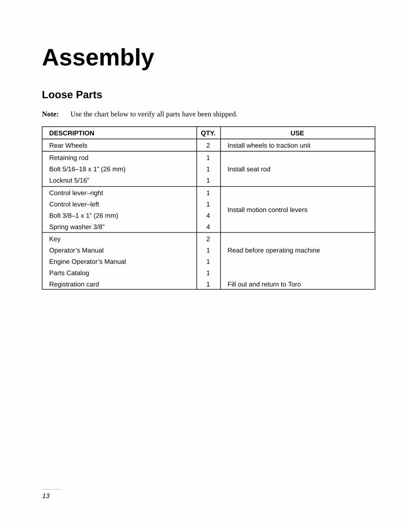
AssemblyLoose Parts
Note: Use the chart below to verify all parts have been shipped.
DESCRIPTION QTY. USE
Rear Wheels 2 Install wheels to traction unit
Retaining rod
Bolt 5/16–18 x 1” (26 mm)
Locknut 5/16”
1
1
1
Install seat rod
Control lever–right
Control lever–left
Bolt 3/8–1 x 1” (26 mm)
Spring washer 3/8”
1
1
4
4
Install motion control levers
Key
Operator’s Manual
Engine Operator’s Manual
Parts Catalog
Registration card
2
1
1
1
1
Read before operating machine
Fill out and return to Toro

Assembly
14
Install Drive Wheels
1. Uncrate mower.
1. Remove wheel bolts or nuts from rear wheelhubs.
2. Align holes. Mount drive wheels with the valvestem to the outside of the traction unit.
3. Secure using wheel bolts or nuts provided.Torque to 95ft–lbs (128 N�M).
Tire Pressure
Check the air pressure in the front and rear tires(Fig. 1).
Pressure: 13 psi (90 kPa)
1
m–1872
Figure 1
1. Valve stem
Install Seat Retaining Rod
4. Tilt seat up. Remove 5/16” (8mm) locknut frombolt attaching seat retaining rod to seat frame(Fig. 2).
5. Remove retaining rod from seat and insert the”L” shaped end of the rod into the hole directlyabove the left–side hydraulic pump mountinghardware (Fig. 2).
6. Place the seat retaining rod to the outside of themounting tab of the seat frame and secure with5/16–18 x 1” (26 mm) bolt and 5/16” (8mm)locknut (Fig. 2).
7. Tighten until snug, then loosen so the rod pivotsfreely.
3
1
m–3750
2
Figure 2
1. L end of retaining rod2. Locknut 5/16”
3. Bolt 5/16–18 x 1” (26 mm)

Assembly
15
Install Motion Control Levers
8. Remove the (4) 3/8–16 x 1” (26 mm) bolts and(4) 3/8” spring washers which attach the motioncontrol levers to the control arm shafts forshipping (Fig. 3).
9. Place the levers (with the mounting platetowards the rear) on the outside of the controlarm shaft and secure with (4) 3/8–16 x 1”(26 mm) bolts and (4) 3/8” spring washers(Fig. 3).
10. Position the lever so the bolts are in the center ofthe slots on the lever mounting plate and tightenuntil snug.
11. Align the front\rear position of the levers, witheach other, in the neutral position. Loosenhardware and adjustment by sliding/tilting thelever(s) forward or backward until properlyaligned(Fig. 3).
m–3751
12
3
Figure 3
1. Mounting plate2. Bolt 3/8–18 x 1” (26 mm)
3. Spring washer 3/8”
12. If the ends of the levers hit against each other,while in the drive position (Fig 4) (levers rotatedin as far as possible) make adjustments bymoving the levers outwards to the neutral lockposition and carefully bend them outward. Movethem back to the drive position and check forclearance. Repeat if necessary.
Figure 4

Assembly
16
Activate the Battery
Bulk electrolyte with 1.260 specific gravity must bepurchased from a local battery supply outlet.
1. Remove the battery from the machine.
IMPORTANT: Be careful not to damage thelong vent tube when removing the batterybox.
POTENTIAL HAZARD• Battery electrolyte contains sulfuric acid
which is a deadly poison and it causessevere burns.
WHAT CAN HAPPEN• If you carelessly drink electrolyte you could
die or if it gets onto your skin you will beburned.
HOW TO AV OID THE HAZARD• Do not drink electrolyte and avoid contact
with skin, eyes or clothing. Wear safetyglasses to shield your eyes and rubbergloves to protect your hands.
• Fill the battery where clean water is alwaysavailable for flushing the skin.
• Follow all instructions and comply with allsafety messages on the electrolyte container.
2. Remove filler caps from the battery. Slowly pourelectrolyte into each cell until the electrolytelevel is up to the lower part of the tube (Fig. 5).
1
2
3
m–1262
Figure 5
1. Filler caps2. Electrolyte
3. Lower part of the tube
3. Leave the covers off and connect a 3 to 4 ampbattery charger to the battery posts (Fig. 6).Charge the battery at a rate of 4 amperes or lessfor 4 hours (12 volts).
4
1
23
m–1254
Figure 6
1. Positive post2. Negative post
3. Charger red (+) wire4. Charger black (–) wire

Assembly
17
POTENTIAL HAZARD• Charging battery produces gasses.
WHAT CAN HAPPEN• Battery gasses can explode.
HOW TO AV OID THE HAZARD• Keep cigarettes, sparks and flames away
from battery.
4. When the battery is fully charged, disconnect thecharger from the electrical outlet then from thenegative and positive battery posts (Fig. 6).
5. Slowly pour electrolyte into each cell until thelevel is once again up to the lower part of thetube and install covers (Fig. 5).
Install Battery
1. Position battery in tray with terminal poststoward the left hand side of mower (Fig. 7).
2. Slide the red terminal boot onto the positive(red) battery cable.
3. Install the positive (red) battery cable to positive(+) battery terminal then negative battery cableand ground wire to the negative (–) batteryterminal.
4. Secure cables with (2) 1/4 x 3/4” (19 mm) bolts1/4” washers and 1/4” locknuts (Fig. 7).
5. Secure battery with J-bolts, hold down clampand (2) 1/4” washers and (2) 1/4” wing nuts(Fig. 7).
6. Position drain tube away from belts and otherparts to prevent corrosion.
1m–3752
9 5
2
6
7
10
4
3
8
11
7
12
Figure 7
1. Battery2. Terminal boot3. Positive battery cable4. Negative battery cable5. Ground wire6. Bolt 1/4–20 x 3/4” (19 mm)
7. Washer 1/4”8. Locknut 1/4”9. Battery clamp10. J-bolts11. Wing nut 1/4”12. Drain Tube

Assembly
18
Hydraulic System
Checking the Hydraulic Fluid
Check the hydraulic fluid level before engine is firststarted.
Fluid Type: Mobil 1 15W–50 synthetic motor oil.
IMPORTANT: Use only oil specified. Otherfluids could cause system damage.
Hydraulic System Oil Capacity: 2.1 qt. (2.0 l)
1. Position machine on a level surface and stop theengine and set the parking brake.
2. Clean area around filler neck of hydraulic tank(Fig. 8).
3. Remove cap from filler neck and look inside tocheck fluid level. Fluid level should be to the topof baffle inside the tank (Fig. 8).
4. If level is low, add fluid to raise level to full.
5. Install cap on filler neck.
2
1
3
������
Figure 8
1. Cap2. Baffle
3. Fluid level-Full
Check the Leveling of MowerDeck
Check the level of the deck before machine is first putinto use.
Refer to Mower Leveling and Compression SpringAdjustment in the Maintenance section on page 34.

19
OperationThink Safety First
Please carefully read all the safety instructions onpages 2–10. Knowing this information could helpyou, your family, pets or bystanders avoid injury.
POTENTIAL HAZARD• Loud sound can cause ear damage and loss
of hearing.
WHAT CAN HAPPEN• Ear damge or hearing loss may occur.
HOW TO AV OID THE HAZARD• Wear ear protection when operating this
machine.
Controls
Become familiar with all the controls (Fig. 1) beforeyou start the engine and operate the machine.
7
m–420010
2
5
8
4 9
2
3
8
6
1
Figure 1
1. Ignition switch2. Motion control lever3. Parking brake lever4. Throttle5. Choke
6. Power take off (PTO)7. Height-of-Cut lever8. Fuel cap9. Hourmeter10. Fuel shut-off valve

Operation
20
Parking Brake
Always set the parking brake when you stop themachine or leave it unattended.
IMPORTANT: Do not park on slopes unlesswheels are chocked or blocked.
Setting the Parking Brake
1. Move the motion control levers (Fig. 1) out tothe neutral lock position.
2. Pull back and up on the parking brake lever toset the parking brake (Fig. 2). The parking brakelever should stay firmly in the “ENGAGED”position.
Releasing the Parking Brake
1. Push forward and down on the parking brakelever to release the parking brake (Fig. 2). Theparking brake is “DISENGAGED”.
1
2
m–4121
Figure 2
1. Parking brake-ON 2. Parking brake-OFF

Operation
21
Starting and Stoppingthe Engine
Starting
1. Sit down on the seat and move the motioncontrols to neutral locked position.
2. Set the parking brake; refer to Setting theParking Brake, page 20.
3. Move the PTO (power take off) to “OFF”(Fig. 3).
4. Move the choke control to “ON” position beforestarting a cold engine (Fig. 4).
Note: A warm or hot engine may requirechoking. After engine starts, movechoke control to “OFF” position.
5. Move the throttle control to the “FAST” positionbefore starting a cold engine (Fig. 5).
6. Turn ignition key to “START” to energize starter.When engine starts, release key (Fig. 6).
IMPORTANT: Do not engage starter formore than 10 seconds at a time. If engine failsto start allow 30 second cool-down periodbetween attempts. Failure to follow theseinstructions can burn out starter motor.
7. After the engine starts, move the choke to “OFF”(Fig. 4). If the engine stalls or hesitates, movethe choke back to “ON” for a few seconds. Thenmove the throttle lever to desired setting. Repeatthis as required.
Figure 3
1. PTO-On2. PTO-Off
Figure 4
1. Choke–On2. Choke–Off
1
m–2719
2
1
m–4201
2
Figure 5
1. Fast2. Slow
Figure 6
1. Off2. Run3. Start
2
1
m–2720
12
3
������

Operation
22
Stopping
1. Move the throttle lever to “SLOW” (Fig. 5).
2. Move the PTO (power take off) to “OFF”(Fig. 3).
3. Turn the ignition key to “OFF” (Fig. 6).
Note: If the engine has been working hard oris hot, let it idle for a minute beforeturning the ignition key “OFF.” Thishelps cool the engine before it isstopped. In an emergency, the enginemay be stopped by turning the ignitionkey to “OFF.”
4. Pull wire off spark plug(s) to prevent possibilityof someone accidentally starting the machinebefore transporting or storing machine.
5. Close fuel shut off valve, on front panel beforetransporting or storing machine.
IMPORTANT: Make sure fuel shut off valveis closed before transporting or storingmachine, as fuel leakage may occur.
Operating the Power T ake Off(PTO)
The power take off (PTO) switch engages anddisengages power to the electric clutch.
Engaging the PTO
1. Release pressure on the traction control leversand place in neutral.
2. Release the parking brake, page 20.
3. Pull out on the power take off (PTO) switch toengage (Fig. 7).
1
2
m–4201
Figure 7
1. PTO – Off 2. PTO – On
Disengaging the PTO
1. To disengage push the PTO switch to the “OFF”position (Fig. 7).

Operation
23
The Safety Interlock System
Understanding the Safety InterlockSystem
The safety interlock system is designed to prevent theengine from starting unless:
• You are sitting on the seat
• The parking brake is on “ENGAGED”
• The power take off (PTO) is disengaged “OFF”
• The motion control levers are in neutral lockposition
The safety interlock system also is designed to stopthe engine when the traction controls are moved withthe parking brake on “ENGAGED” or if you risefrom the seat when the PTO is “ON” engaged.
Testing the Safety InterlockSystem
Test the safety interlock system before you use themachine each time. If the safety system does notoperate as described below, have an AuthorizedService Dealer repair the safety system immediately.
1. Sitting on the seat, “ENGAGE” parking brakeand move PTO “ON”. Try starting the engine;the engine should not crank.
2. Sitting on the seat, “ENGAGE” parking brakeand move PTO “OFF”. Move either motioncontrol lever (forward or reverse). Try startingthe engine; the engine should not crank. Repeatwith other motion control lever.
3. Sitting on the seat, “ENGAGE” parking brake,move PTO “OFF” and lock the motion controllevers in neutral. Now start the engine. While theengine is running, release the parking brake,engage the PTO and rise slightly from the seat;the engine should stop.
4. Sitting on the seat, “ENGAGE” parking brake,PTO “OFF” and lock the motion control leversin neutral. Now start the engine. While theengine is running, center the motion controls andmove (forward or reverse); the engine shouldstop.
5. Sitting on the seat, “DISENGAGE” parkingbrake, move PTO switch “OFF” and move themotion control levers to neutral lock position.Try starting the engine; the engine should notcrank.

Operation
24
Driving Forward or Backward
The throttle control regulates the engine speed asmeasured in rpm (revolutions per minute). Place thethrottle control in the “FAST” position for bestperformance. Always operate in the full throttleposition
Forward
1. Release the parking brake; refer to Releasing theParking Brake, page 20.
2. Move levers to the center, un-locked position.
3. To go forward, slowly push the motion controllevers forward (Fig. 8).
Note: Engine will kill if traction controllevers are moved with parking brakeengaged.
To go straight, apply equal pressure to both motioncontrol levers (Fig. 8).
To turn, release pressure on the motion control levertoward the direction you want to turn (Fig. 8).
The farther you move the traction control levers ineither direction, the faster the machine will move inthat direction.
To stop pull the motion control levers to neutral.
4
m–2715
3
1
2
Figure 8
1. Motion controllever-neutral lock position
2. Center un-lock position
3. Forward4. Backward
Backward
1. Move levers to the center, un-locked position.
2. To go backward, slowly pull the motion controllevers rearward (Fig. 8).
To go straight, apply equal pressure to both motioncontrol levers (Fig. 8).
To turn, release pressure on the motion control levertoward the direction you want to turn (Fig. 8).
To stop push the motion control levers to neutral.
Stopping the Machine
To stop the machine, move the traction control leversto neutral and separate to lock, disengage the powertake off (PTO), and turn the ignition key to “OFF” tostop the engine. Also set the parking brake when youleave the machine; refer to Setting the Parking Brake,page 20. Remember to remove the key from theignition switch.
POTENTIAL HAZARD• Someone could move or attempt to operate
the tractor while it is unattended.
WHAT CAN HAPPEN• Children or bystanders may be injured if
they use the tractor.
HOW TO AV OID THE HAZARD• Always remove the ignition key and set the
parking brake when leaving the machine,even if just for a few minutes.

Operation
25
Instruments
Hour Meter
The hour meter records the number of hours theengine has operated. It operates when the engine isrunning. Use these times for scheduling regularmaintenance.
1
m–4202
Figure 9
1. Hour meter
Fuel Tanks
The unit has two fuel tanks, one located on the leftside and one on the right side. Each tank connects tothe fuel shut off valve in the control panel. Fromthere a common fuel line leads to the engine (Fig.10).
To use the right side fuel tank rotate the fuel shut offvalve 1/4 turn to the right from the off location. Thisuses fuel from the right side tank only. When the rightfuel tank is empty, move the fuel shut off valve 1/4turn to the left from the off position.
Close fuel shut off valve, on front panel beforetransporting or storing machine.
Figure 10
1. Shut off valve
Operation
26
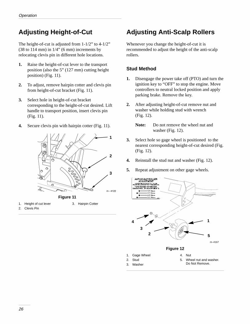
Adjusting Height-of-Cut
The height-of-cut is adjusted from 1-1/2” to 4-1/2”(38 to 114 mm) in 1/4” (6 mm) increments byrelocating clevis pin in different hole locations.
1. Raise the height-of-cut lever to the transportposition (also the 5” (127 mm) cutting heightposition) (Fig. 11).
2. To adjust, remove hairpin cotter and clevis pinfrom height-of-cut bracket (Fig. 11).
3. Select hole in height-of-cut bracketcorresponding to the height-of-cut desired. Lifthandle to transport position, insert clevis pin(Fig. 11).
4. Secure clevis pin with hairpin cotter (Fig. 11).
1
������
3
2
Figure 1 1
1. Height of cut lever2. Clevis Pin
3. Hairpin Cotter
Adjusting Anti-Scalp Rollers
Whenever you change the height-of-cut it isrecommended to adjust the height of the anti-scalprollers.
Stud Method
1. Disengage the power take off (PTO) and turn theignition key to “OFF” to stop the engine. Movecontrollers to neutral locked position and applyparking brake. Remove the key.
2. After adjusting height-of-cut remove nut andwasher while holding stud with wrench(Fig. 12).
Note: Do not remove the wheel nut andwasher (Fig. 12).
3. Select hole so gage wheel is positioned to thenearest corresponding height-of-cut desired (Fig.(Fig. 12).
4. Reinstall the stud nut and washer (Fig. 12).
5. Repeat adjustment on other gage wheels.
m–4167
1
23
4
5
Figure 12
1. Gage Wheel2. Stud3. Washer
4. Nut5. Wheel nut and washer.
Do Not Remove.
Operation
27
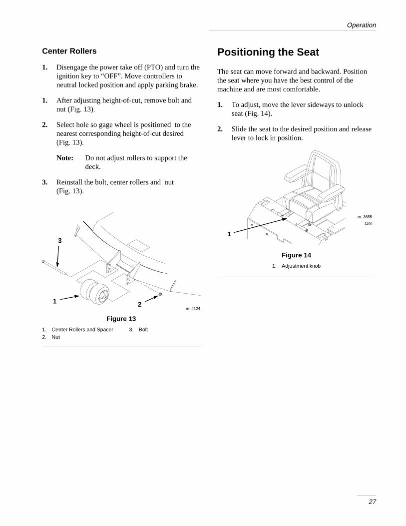
Center Rollers
1. Disengage the power take off (PTO) and turn theignition key to “OFF”. Move controllers toneutral locked position and apply parking brake.
1. After adjusting height-of-cut, remove bolt andnut (Fig. 13).
2. Select hole so gage wheel is positioned to thenearest corresponding height-of-cut desired(Fig. 13).
Note: Do not adjust rollers to support thedeck.
3. Reinstall the bolt, center rollers and nut(Fig. 13).
m–4124
1 2
3
Figure 13
1. Center Rollers and Spacer2. Nut
3. Bolt
Positioning the Seat
The seat can move forward and backward. Positionthe seat where you have the best control of themachine and are most comfortable.
1. To adjust, move the lever sideways to unlockseat (Fig. 14).
2. Slide the seat to the desired position and releaselever to lock in position.
1
1200
m–3655
Figure 14
1. Adjustment knob

Operation
28
Pushing the Machine by Hand
IMPORTANT: Always push the machine byhand. Never tow the machine becausehydraulic damage may occur.
To Push the Machine
1. Disengage the power take off (PTO) and turn theignition key to “OFF” to stop the engine.
2. Rotate the by-pass valves counterclockwise 1turn to push. This allows hydraulic fluid toby-pass the pump enabling the wheels to turn(Fig. 15).
IMPORTANT: Never rotate by-pass valvemore than 2 turns so the valve does not comeout of the body causing fluid to run out.
To Operate the Machine
1. Turn the by-pass valves in to operate (Fig. 15).
Note: The machine will not drive unlessby-pass valves are turned in.
1
Figure 15
1. By-pass valve
Side Discharge
The mower has a hinged grass deflector that dispersesclippings to the side and down toward the turf.
POTENTIAL HAZARD• Without the grass deflector or complete
grass catcher assembly mounted in place,you and others are exposed to blade contactand thrown debris.
WHAT CAN HAPPEN• Contact with rotating mower blade(s) and
thrown debris will cause injury or death.
HOW TO AV OID THE HAZARD• NEVER remove the grass deflector from
the mower because the grass deflectorroutes material down toward the turf. If thegrass deflector is ever damaged, replace itimmediately.
• Never put your hands or feet under themower.
• Never try to clear discharge area or mowerblades unless you move the power take off(PTO) to “OFF” and rotate the ignition keyto “OFF.” Also remove the key and pull thewire(s) off the spark plug(s).

Operation
29
Tips for Mowing Grass
Fast Throttle Setting
For best mowing and maximum air circulation,operate the engine at “FAST.” Air is required tothoroughly cut grass clippings, so do not set theheight-of-cut so low as to totally surround the mowerby uncut grass. Always try to have one side of themower free from uncut grass, which allows air to bedrawn into the mower.
Cutting a Lawn for the First Time
Cut grass slightly longer than normal to ensure thecutting height of the mower does not scalp anyuneven ground. However, the cutting height used inthe past is generally the best one to use. When cuttinggrass longer than six inches tall, you may want to cutthe lawn twice to ensure an acceptable quality of cut.
Cut 1/3 of the Grass Blade
It is best to cut only about 1/3 of the grass blade.Cutting more than that is not recommended unlessgrass is sparse, or it is late fall when grass growsmore slowly.
Mowing Direction
Alternate mowing direction to keep the grass standingstraight. This also helps disperse clippings whichenhances decomposition and fertilization.
Mow at Correct Intervals
Normally, mow every four days. But remember, grassgrows at different rates at different times. So tomaintain the same cutting height, which is a goodpractice, mow more often in early spring. As thegrass growth rate slows in mid summer, mow lessfrequently. If you cannot mow for an extended period,first mow at a high cutting height; then mow againtwo days later at a lower height setting.
Cutting Speed
To improve cut quality, use a slower ground speed.
Avoid Cutting Too Low
If the cutting width of the mower is wider than themower you previously used, raise the cutting heightto ensure that uneven turf is not cut too short.
Long Grass
If the grass is ever allowed to grow slightly longerthan normal, or if it contains a high degree ofmoisture, raise the cutting height higher than usualand cut the grass at this setting. Then cut the grassagain using the lower, normal setting.
When Stopping
If the machine’s forward motion must be stoppedwhile mowing, a clump of grass clippings may droponto your lawn. To avoid this, move onto apreviously cut area with the blades “ENGAGED”.
Keep the Underside of the Mower Clean
Clean clippings and dirt from the underside of themower after each use. If grass and dirt build up insidethe mower, cutting quality will eventually becomeunsatisfactory.
Blade Maintenance
Maintain a sharp blade throughout the cutting seasonbecause a sharp blade cuts cleanly without tearing orshredding the grass blades. Tearing and shreddingturns grass brown at the edges, which slows growthand increases the chance of disease. Check the cutterblades daily for sharpness, and for any wear ordamage. File down any nicks and sharpen the bladesas necessary. If a blade is damaged or worn, replace itimmediately with a genuine TORO replacementblade.

30
MaintenanceService Interval Chart
Service OperationEachUse
8Hours
25Hours
50Hours
100Hours
200Hours
300Hours
StorageService
Hydraulic fluid–check level Initial Initial X X
Oil—check level X X
Oil—change* Initial X X
Oil Filter–change (200 hours orevery other oil change)
X X
Hydraulic filter–change Initial X X
Safety System—check X X
Chassis—grease* X X
Linkage bushings—oil* X X
Foam Air Cleaner—service* X X
Paper Air Cleaner—service* X X
Paper Air Cleaner—replace* X X
Spark Plug(s)—check X X
Belts—check for wear/cracks X X
Gasoline—drain X
Cooling systems–clean X X X
Hydraulic lines–check X X
Battery–check electrolyte X X
Battery–charge, Disconnect cables X
Fuel Filter—replace X X
Tires—check pressure X X
Chipped Surfaces—paint X
Cutting Blades – check X X
Blade Spindle Bearings – grease X
Idler Pulley Pivot X
Mower Housing – clean X X
* More often in dusty, dirty conditions

Maintenance
31
POTENTIAL HAZARD• If you leave the key in the ignition switch, someone could start the engine.
WHAT CAN HAPPEN• Accidental starting of the engine could seriously injure you or other bystanders.
HOW TO AV OID THE HAZARD• Remove the key from the ignition switch and pull the wire(s) off the spark plug(s)
before you do any maintenance. Also push the wire(s) aside so it does notaccidentally contact the spark plug(s).
Cutting Blades
Maintain a sharp blade throughout the cutting seasonbecause a sharp blade cuts cleanly without tearing orshredding the grass blades. Tearing and shreddingturns grass brown at the edges, which slows growthand increases the chance of disease.
Check the cutter blades daily for sharpness, and forany wear or damage. File down any nicks andsharpen the blades as necessary. If a blade is damagedor worn, replace it immediately with a genuine TOROreplacement blade. For convenient sharpening andreplacement, you may want to keep extra blades onhand.
POTENTIAL HAZARD• A blade that is worn or damaged could
break apart and pieces could be thrown atbystanders or at you as you use the mower.
WHAT CAN HAPPEN• Pieces of blade that may be thrown could
seriously injure or kill you or bystanders.
HOW TO AV OID THE HAZARD• Periodically inspect the blade for wear and
damage. Immediately install a new blade ifit is worn or damaged.
Before Inspecting or Servicing theBlades
Park the machine on a level surface, disengage theblade control (PTO) and set the parking brake. Turnthe ignition key to “OFF” to stop the engine. Removethe key and disconnect the spark plug wire(s) fromthe spark plug(s).
Maintenance
32
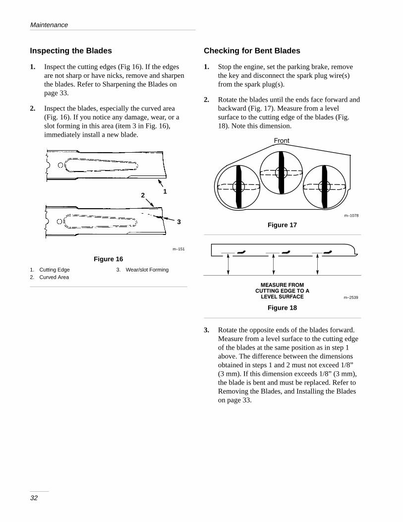
Inspecting the Blades
1. Inspect the cutting edges (Fig 16). If the edgesare not sharp or have nicks, remove and sharpenthe blades. Refer to Sharpening the Blades onpage 33.
2. Inspect the blades, especially the curved area(Fig. 16). If you notice any damage, wear, or aslot forming in this area (item 3 in Fig. 16),immediately install a new blade.
12
3
m–151
Figure 16
1. Cutting Edge2. Curved Area
3. Wear/slot Forming
Checking for Bent Blades
1. Stop the engine, set the parking brake, removethe key and disconnect the spark plug wire(s)from the spark plug(s).
2. Rotate the blades until the ends face forward andbackward (Fig. 17). Measure from a levelsurface to the cutting edge of the blades (Fig.18). Note this dimension.
�����
m–1078
Figure 17
���� �� � ��������� ����� ��� ����� �� ���� m–2539
Figure 18
3. Rotate the opposite ends of the blades forward.Measure from a level surface to the cutting edgeof the blades at the same position as in step 1above. The difference between the dimensionsobtained in steps 1 and 2 must not exceed 1/8”(3 mm). If this dimension exceeds 1/8” (3 mm),the blade is bent and must be replaced. Refer toRemoving the Blades, and Installing the Bladeson page 33.

Maintenance
33
POTENTIAL HAZARD• A blade that is bent or damaged could
break apart and pieces could be thrown atbystanders or at you as you use the mower.
WHAT CAN HAPPEN• Pieces of blade that may be thrown could
seriously injure or kill you or bystanders.
HOW TO AV OID THE HAZARD• Always replace bent or damaged blade with
a new blade.• Never file or create sharp notches in the
edges or surfaces of blade.
Removing the Blades
Blades must be replaced if a solid object is hit, if theblade is out of balance or is bent. To ensure optimumperformance and continued safety conformance of themachine, use genuine TORO replacement blades.Replacement blades made by other manufacturersmay result in non-conformance with safety standards.
Hold the blade end using a rag or thickly-paddedglove. Remove the blade bolt, spring disk and bladefrom the spindle shaft (Fig. 19).
1
3
2
4
������
5
Figure 19
1. Sail Area of Blade2. Blade3. Spring Disk
4. Blade Bolt5. Split Lockwasher
Sharpening the Blades
1. Use a file to sharpen the cutting edge at bothends of the blade (Fig. 20). Maintain the originalangle. The blade retains its balance if the sameamount of material is removed from both cuttingedges.
1
m–1854
Figure 20
1. Sharpen at original angle
2. Check the balance of the blade by putting it on ablade balancer (Fig. 21). If the blade stays in ahorizontal position, the blade is balanced and canbe used. If the blade is not balanced, file somemetal off the end of the sail area only (Fig. 19).Repeat this procedure until the blade is balanced.
12
m–1855
Figure 21
1. Blade 2. Balancer
Installing the Blades
1. Install the blade onto the spindle shaft (Fig. 19).
IMPORTANT: The curved part of the blademust be pointing upward toward the inside ofthe mower to ensure proper cutting.
2. Install the flat washer, lock washer and bladebolt (Fig. 19). Torque the blade bolt to 85–110ft-lb (115–150 N�m).

Maintenance
34
Mower Leveling
1. Position mower on a flat surface. Stop theengine, set the parking brake, remove the keyand disconnect the spark plug wire(s) from thespark plug(s).
2. Check tire pressure of all four (4) tires. Ifneeded, adjust to 13 psi (90 kPa)
3. Set anti–scalp rollers to top holes or removethem completely for this adjustment.
4. Raise the deck to the transport position (Fig. 22).Take force off of the two large deck lift springsby loosening jam nut and front spring nut, infront of each spring, as far as possible (Fig. 23).
5. Place two 1-1/4” (35 mm) thick blocks underrear left and right lower edge of mower. Placeone 1-3/8” (44 mm) block under front centerlower edge of mower. Not under anti–scalp rollerbrackets. Lower mower to the 1-1/2” (38 mm)height-of-cut position (Fig. 22).
1
2m–4122
Figure 22
1. Transport position 2. 1-1/2” (38 mm)height-of-cut
6. Loosen bottom chain bolt in slot at rear of deck.Repeat for opposite side. (Fig. 23).
Note: Do not loosen front chain hardware.
7. Loosen front and rear locking nut on either sideof front swivel. Loosen until front chains areloose and deck is supported by blocks. Repeatfor opposite side. (Fig. 23).
Note: When hardware is loose, deck willrotate the lift handle up out of position.
8. When hardware is loosened, remaining tensionin the large support springs will tend to rotate thedeck lift handle up, out of the 1–1/2” position.Press down on the rear deck support arm tofirmly return the deck lift handle to the 1–1/2”position (Fig. 23).
Note: Do not push on deck lift handle.
9. While continuing to press down on rear decksupport arm, take the slack out of the rear chainand tighten hardware at the bottom (Fig. 23).Downward pressure may now be released.Repeat for opposite side.
10. Adjust front swivel using rear locking nut untilthe front chain is tight and front of deck is stilltouching block. Tighten front locking nut.Repeat for opposite side.
13
4
5
6
7
2
8
������
9
Figure 23
1. Bottom chain bolt2. Top chain bolt3. Front swivel4. 10-1/4” (260 mm) spring
compressed
5. Rear Locking Nut6. Front Locking Nut7. Rear Deck Support Arm8. Front Spring Nut9. Jam Nut
11. Recheck that blocks fit just snuggly under themower and that tension on all four chains areapproximately equal.

Maintenance
35
12. Raise deck to 3 inch height of cut and measureactual height from blade tips to ground. Heightof cut for the front blade tips should be3.00 ±.125 (76mm ± 3mm). Height of cut forrear blade tips should be 3.25±.125(83mm± 3mm).Readjust if needed.
Note: When checking blade tip heights makesure blades are not bent and checkblade pointing front to rear.
13. Install anti–scalp rollers for proper height-of-cutand tighten securely. See Adjusting Anti ScalpRollers on page 26.
14. Raise deck lift lever to the transport position,(Fig. 22).
15. Adjust compression springs by turning the frontspring nuts so the distance between the two largewashers is 10-1/4” (260 mm). Then tighten jamnut (Fig. 23).
Note: Make sure all hardware is tight.
Greasing the Bearings
The cutting unit must be lubricated regularly. Refer tothe Service Interval Chart on page 30. Grease withNo. 2 general purpose lithium base or molybdenumbase grease.
1. Stop the engine, set the parking brake, removethe key and disconnect the spark plug wire(s)from the spark plug(s).
2. Grease the fittings on the three spindle bearings(Fig. 24).
3. Grease the idler pulley pivot (Fig. 24).
4. Grease the fittings on the push arms(Fig. 24).
������
Figure 24

Maintenance
36
Replacing the Grass Deflector
1. Stop the engine, set the parking brake, removethe key and disconnect the spark plug wire(s)from the spark plug(s).
2. Remove the locknuts, bolts and springs holdingthe deflector mounts to the pivot brackets(Fig. 25).
3. If the pivot brackets need to be replaced, removethe carriage bolts and cone locknuts holding theold brackets to the top of the discharge opening,then install the replacement pivot brackets. Makesure the carriage bolt heads are on the inside ofthe cutting unit (Fig. 25).
4. Install the deflector mounts onto the pivotbrackets with the bolts, springs and locknuts.Make sure the straight ends of the springs arepositioned between the deflector mounts and thegrass deflector (Fig. 25).
5. Tighten the locknuts until they contact the pivotbrackets (Fig. 25).
IMPORTANT: The grass deflector must bespring-loaded in the down position. Lift thedeflector up to test that it snaps to the fulldown position.
2
4
7
1 5 6
3
m–2549
Figure 25
1. Bolt2. Deflector Mount3. Spring4. Cone Locknut
5. Pivot Bracket6. Carriage Bolt7. Locknut
Tire Pressure
Maintain the air pressure in the front and rear tires asspecified. Uneven tire pressure can cause uneven cut.Check the pressure at the valve stem after every 50operating hours or monthly, whichever occurs first(Fig. 26). Check the tires when they are cold to getthe most accurate pressure reading.
Pressure: 13 psi (90 kPa) drive wheels and castorwheels.
1
m–1872
Figure 26
1. Valve stem

Maintenance
37
Replacing the Deck Belt
Squealing when the belt is rotating, blades slippingwhen cutting grass, frayed belt edges, burn marks andcracks are signs of a worn deck belt. Replace the deckbelt if any of these conditions are evident.
1. Stop the engine, set the parking brake, removethe key and disconnect the spark plug wire(s)from the spark plug(s).
2. Remove belt covers over outside spindles.
3. Loosen outer nut on spring eye bolt (Fig. 27).
2
������
1 43
7
5
6
Figure 27
Top View
1. Outer Nut2. Idler Pulley3. Idler Arm4. Spring Eye Bolt
5. Spring6. 9.375 ±.125 (238 mm
±.3 mm)
7. Deck Belt
4. Remove belt. Start at outside pulley and rotateoff (Fig. 28).
Note: Dot not remove spring.
POTENTIAL HAZARD• Spring is under tension when installed.
WHAT CAN HAPPEN• Stored spring energy can cause personal
injury.
HOW TO AV OID THE HAZARD• Do not remove spring from spring eye bolt.
5. Remove spring loaded idler pulley (Fig. 27).
6. Route new belt through idler arm (Fig. 27).
7. Reinstall idler pulley and route belt onto otherpulleys (Fig. 28).
8. Retighten outer nut on spring eye bolt (Fig. 27).
Note: Check spring length. The spring shouldmeasure 9.375” ± .125” (238 mm ±.3mm) when installed. Adjust if it doesnot (Fig. 27).
9. Install belt covers over outside spindles.
1
2
3
4
5
������
Figure 28
Top View
1. Deck Belt2. Idler Arm3. Outside Pulley
4. Spring5. Idler Pulley

Maintenance
38
Air Cleaner
Foam Element: Clean and re-oil after every 25operating hours.
Paper Element: Clean after every 100 operatinghours. Replace after every 300 operating hours oryearly. Which ever comes first.
Note: Service the air cleaner more frequently(every few hours) if operatingconditions are extremely dusty orsandy.
Removing the Foam and Paper Elements
1. Disengage the power take off (PTO), set theparking brake, and turn the ignition key to“OFF” to stop the engine. Remove the key.
2. Clean around the air cleaner to prevent dirt fromgetting into the engine and causing damage.Unlatch two side latches and remove the aircleaner cover (Fig. 29).
14
2
������
3 5
6
Figure 29
1. Cover2. Foam element3. Paper element
4. Wing nut5. Air cleaner base6. Latches
3. Carefully remove the foam element from thepaper element (Fig. 29).
4. Unscrew the wing nut and remove the paperelement (Fig. 29).
Cleaning the Foam and Paper Elements
1. Foam Element
A. Wash the foam element in liquid soap andwarm water. When the element is clean,rinse it thoroughly.
B. Dry the element by squeezing it in a cleancloth (do not wring).
C. Soak element in new engine oil. (Fig. 30).Squeeze the element to remove excess oil.
IMPORTANT: Replace the foam element if itis torn or worn.
2
1
Figure 30
1. Foam element 2. Oil

Maintenance
39
2. Paper Element
A. Lightly tap the element on a flat surface toremove dust and dirt (Fig. 31).
B. Inspect the element for tears, an oily film,and damage to the rubber seal.
IMPORTANT: Never clean the paper elementwith pressurized air or liquids, such assolvent, gas, or kerosene. Replace the paperelement if it is damaged or cannot be cleanedthoroughly.
1
2
������
ÏÏÏÏÏÏÏÏÏÏÏÏÏÏÏÏÏÏÏÏÏÏÏÏÏÏÏÏÏÏÏÏÏÏÏÏ
Figure 31
1. Paper element 2. Rubber seal
Installing the Foam and Paper Elements
IMPORTANT: To prevent engine damage,always operate the engine with the completefoam and paper air cleaner assemblyinstalled.
1. Carefully slide the foam element into the paperair cleaner element (Fig. 29).
2. Place the air cleaner assembly onto the aircleaner base and install wing nut (Fig. 29).
3. Install the air cleaner cover and latch (Fig. 29).
Engine Oil
Change oil:
• After the first 8 operating hours.
• After every 100 operating hours.
Note: Change oil more frequently whenoperating conditions are extremelydusty or sandy.
Oil Type: Detergent oil (API service SG or SH)
Crankcase Capacity: w/filter, 1.9 qt. (1.8 l)
Viscosity: See table below
m–4292
USE THESE SAE VISCOSITY OILS

Maintenance
40
Checking Oil Level
1. Park the machine on a level surface, disengagethe power take off (PTO) and turn the ignitionkey to “OFF” to stop the engine. Remove thekey.
2. Clean around the oil dipstick (Fig. 32) so dirtcannot fall into the filler hole and damage theengine.
3. Unscrew the oil dipstick and wipe the end clean(Fig. 32).
4. Slide the oil dipstick fully into the filler tube, donot thread onto tube (Fig. 32). Pull the dipstickout and look at the end. If oil level is low, slowlypour only enough oil into the filler tube to raisethe level to the “FULL” mark.
IMPORTANT: Do not overfill the crankcasewith oil because the engine may be damaged.
13
2
������
Figure 32
1. Oil dipstick2. Filler tube
3. Dipstick end
Changing/Draining Oil
1. Start the engine and let it run five minutes. Thiswarms the oil so it drains better.
2. Park the machine so that the drain side is slightlylower than the opposite side to assure the oildrains completely. Then disengage the powertake off (PTO), set the parking brake, and turnthe ignition key to “OFF” to stop the engine.Remove the key.
3. Place a pan below the oil drain. Remove the oildrain cap (Fig. 33).
4. When oil has drained completely, install thedrain cap.
Note: Dispose of the used oil at a certifiedrecycling center.
1
������
Figure 33
1. Oil drain cap
5. Slowly pour approximately 80% of the specifiedamount of oil specified, page 39, into the fillertube (Fig. 32). Now check the oil level; refer toChecking Oil Level, page 40. Slowly addadditional oil to bring to “FULL” mark ondipstick.

Maintenance
41
Change Oil Filter
Replace the oil filter every 200 hours or every otheroil change.
Note: Change oil filter more frequently whenoperating conditions are extremelydusty or sandy.
1. Drain the oil from the engine; refer toChanging/Draining Oil, page 40.
2. Remove the old filter (Fig. 34).
3. Apply a thin coat of new oil to the rubber gasketon the replacement filter (Fig. 34).
1
2
������
Figure 34
1. Oil filter 2. Adapter
4. Install the replacement oil filter to the adapter.Turn the oil filter clockwise until the rubbergasket contacts the filter adapter, then tighten thefilter an additional 3/4 turn (Fig. 34).
5. Fill the crankcase with the proper type of newoil; refer to Changing/Draining Oil, page 40.
Spark Plug
Check the spark plug(s) after every 100 operatinghours. Make sure the air gap between the center andside electrodes is correct before installing the sparkplug. Use a spark plug wrench for removing andinstalling the spark plug(s) and a gapping tool/feelergauge to check and adjust the air gap. Install a newspark plug(s) if necessary.
Type: Champion RCJ8Y (or equivalent) Air Gap:0.040 in. (1.0 mm)
Removing the Spark Plug (s)
1. Disengage the power take off (PTO), set theparking brake, and turn the ignition key to“OFF” to stop the engine. Remove the key.
2. Pull the wire(s) off the spark plug(s) (Fig. 35).Now clean around the spark plug(s) to preventdirt from falling into the engine and potentiallycausing damage.
3. Remove the spark plug(s).
2
1
������
Figure 35
1. Spark plug wire 2. Spark plug

Maintenance
42
Checking the Spark Plug
1. Look at the center of the spark plug(s) (Fig. 36).If you see light brown or gray on the insulator,the engine is operating properly. A black coatingon the insulator usually means the air cleaner isdirty.
IMPORTANT: Never clean the spark plug(s).Always replace the spark plug(s) when it hasa black coating, worn electrodes, an oily film,or cracks.
2. Check the gap between the center and sideelectrodes (Fig. 36). Bend the side electrode(Fig. 36) if the gap is not correct.
0.040 in.(1.0 mm)
2 3
1
m–3215
Figure 36
1. Center electrode insulator2. Side electrode
3. Air gap (not to scale)
Installing the Spark Plug (s)
1. Install the spark plug(s). Make sure the air gap isset correctly.
2. Tighten the spark plug(s) to 11 ft-lb (15 N.m).
3. Push the wire(s) onto the spark plug(s) (Fig. 35).
Greasing and Lubrication
Lubricate the machine when shown on the CHECKSERVICE REFERENCE AID decal (Fig. 37). Greasemore frequently when operating conditions areextremely dusty or sandy.
Grease Type: General-purpose grease.
How to Grease
1. Disengage the power take off (PTO) and turn theignition key to “OFF” to stop the engine.Remove the key.
2. Clean the grease fittings with a rag. Make sure toscrape any paint off the front of the fitting(s).
3. Connect a grease gun to the fitting. Pump greaseinto the fittings until grease begins to ooze out ofthe bearings.
4. Wipe up any excess grease.
Where to Add Grease
Lubricate the grease fittings as shown on the CHECKSERVICE REFERENCE AID decal (Fig. 37).
Figure 37

Maintenance
43
Grease Front Castor Pivots
Lubricate the front castor pivots once a year.
1. Remove hex plug and cap. Thread a grease zerkinto hole.
2. Pump grease into zerk until it oozes out aroundtop beraring.
3. Remove grease zerk in hole. Reinstall hex plugand cap.
Cleaning the Cooling System
Clean the air intake screen from grass and debrisbefor each use.
Clean cooling fins and engine shrouds every 300hours or yearly, which ever comes first.
1. Stop the engine, set the parking brake, removethe key and disconnect the spark plug wire(s)from the spark plug(s).
2. Remove air–intake screen, cylinder covers andfan housing.
3. Clean debris and grass from parts.
4. Reinstall air–intake screen, cylinder covers andfan housing.
m–4295
1
2
3
4
Figure 38
1. Air–intake Screen2. Fan Housing
3. Cylinder Cover4. Cylinder Cover
Maintenance
44
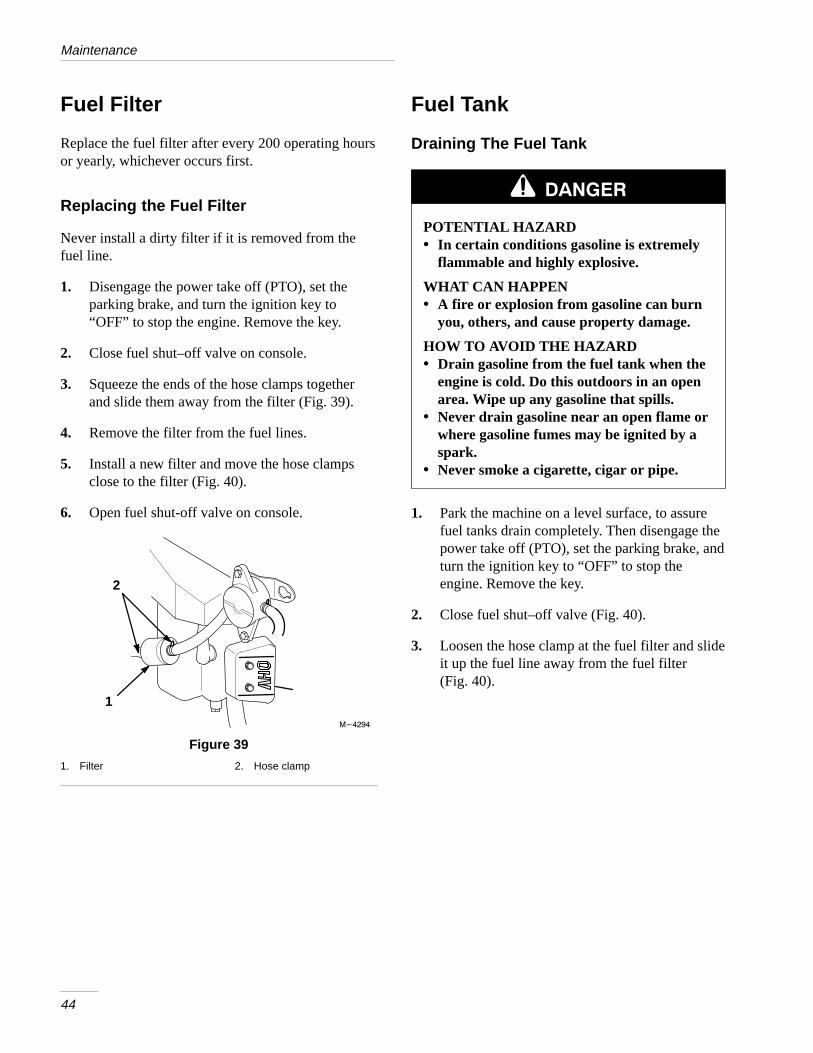
Fuel Filter
Replace the fuel filter after every 200 operating hoursor yearly, whichever occurs first.
Replacing the Fuel Filter
Never install a dirty filter if it is removed from thefuel line.
1. Disengage the power take off (PTO), set theparking brake, and turn the ignition key to“OFF” to stop the engine. Remove the key.
2. Close fuel shut–off valve on console.
3. Squeeze the ends of the hose clamps togetherand slide them away from the filter (Fig. 39).
4. Remove the filter from the fuel lines.
5. Install a new filter and move the hose clampsclose to the filter (Fig. 40).
6. Open fuel shut-off valve on console.
1
2
������
Figure 39
1. Filter 2. Hose clamp
Fuel Tank
Draining The Fuel Tank
POTENTIAL HAZARD• In certain conditions gasoline is extremely
flammable and highly explosive.
WHAT CAN HAPPEN• A fire or explosion from gasoline can burn
you, others, and cause property damage.
HOW TO AV OID THE HAZARD• Drain gasoline from the fuel tank when the
engine is cold. Do this outdoors in an openarea. Wipe up any gasoline that spills.
• Never drain gasoline near an open flame orwhere gasoline fumes may be ignited by aspark.
• Never smoke a cigarette, cigar or pipe.
1. Park the machine on a level surface, to assurefuel tanks drain completely. Then disengage thepower take off (PTO), set the parking brake, andturn the ignition key to “OFF” to stop theengine. Remove the key.
2. Close fuel shut–off valve (Fig. 40).
3. Loosen the hose clamp at the fuel filter and slideit up the fuel line away from the fuel filter(Fig. 40).

Maintenance
45
4. Pull the fuel line off fuel filter (Fig. 40).
5. Open fuel shut-off valve for left and right tanks.Allow gasoline to drain into a gas can or drainpan. (Fig. 40).
Note: Now is the best time to install a newfuel filter because the fuel tank isempty.
6. Install the fuel line onto the fuel filter. Slide thehose clamp close to the fuel filter to secure thefuel line (Fig. 40).
1
24
������
3
Figure 40
1. Fuel shut-off valve2. Fuel filter
3. Hose clamp4. Fuel line
Hydraulic System
Checking the Hydraulic Fluid
Check the hydraulic fluid level:
• Before engine is first started.
• After first 8 operating hours.
• After 25 operating hours.
Fluid Type: Mobil 1 15W–50 synthetic motor oil.
IMPORTANT: Use only oil specified. Otherfluids could cause system damage.
System Capacity: 2.1 qt. (2.0 l)
1. Position machine on a level surface and stop theengine and set the parking brake.
2. Clean area around filler neck of hydraulic tank(Fig. 41).
3. Remove cap from filler neck and look inside tocheck fluid level. Fluid level should be above thebaffle inside the tank (Fig. 41).
4. If level is low, add fluid to raise level to abovethe baffle (Fig. 41).
5. Install cap on filler neck.
2
1
3
������
Figure 41
1. Cap2. Baffle
3. Fluid level-Full

Maintenance
46
POTENTIAL HAZARD• Hydraulic fluid escaping under pressure
can penetrate skin and cause injury.
WHAT CAN HAPPEN• Fluid accidentally injected into the skin
must be surgically removed within a fewhours by a doctor familiar with this form ofinjury or gangrene may result.
HOW TO AV OID THE HAZARD• Keep body and hands away from pin hole
leaks or nozzles that eject high pressurehydraulic fluid.
• Use cardboard or paper to find hydraulicleaks.
Replacing the Hydraulic Filter
Change the hydraulic filter:
• After the first 8 operating hours.
• After every 200 operating hours.
1. Position machine on a level surface, stop theengine, and remove key from ignition switch.
IMPORTANT: Do not substitute automotiveoil filter or severe hydraulic system damagemay result.
2. Remove hydro cap and temporarily coveropening with a plastic bag and rubber band toprevent all hydro fluid from draining out.
A. Place drain pan under filter, remove the oldfilter and wipe the filter adapter gasketsurface clean (Fig. 42).
m–4117
1
Figure 42
1. Hydraulic filter
3. Apply a thin coat hydro fluid to the rubbergasket on the replacement filter (Fig. 43).
4. Install replacement hydraulic filter onto the filteradapter. Do not tighten.
5. Remove plastic bag from tank opening and allowfilter to fill with hydro fluid.
6. When fluid overflows filter turn the oil filterclockwise until the rubber gasket contacts thefilter adapter, then tighten the filter an additional1/2 turn (Fig. 43).
m–1256
1
2
3
Figure 43
1. Hydraulic filter2. Gasket
3. Adapter
7. Clean up any spilled fluid.

Maintenance
47
8. Start engine and let run for about two minutes topurge air from the system. Stop the engine andcheck for leaks. If one or both wheels will notdrive, refer Bleeding Hydraulic System, page 47.
9. Check fluid level in hydraulic tank and add toraise level to the top of baffle. DO NOT OVERFILL.
Bleeding Hydraulic System
The traction system is self bleeding, however, it maybe necessary to bleed the system if fluid is changed orafter work is performed on the system.
1. Raise rear of the machine so wheels are off theground and support with jack stands.
2. Start the engine and run at idle speed. Engagetraction on one side and spin the wheel by hand.
3. When the wheel begins to spin on its own, keepit engaged until wheel drives smoothly.(minimum 2 minute)
4. Check hydraulic fluid level as it drops and addas required to maintain proper level.
5. Repeat procedure on opposite wheel.
Check Hydraulic Lines
After every 100 operating hours, check hydrauliclines and hoses for leaks, loose fittings, kinked lines,loose mounting supports, wear, weather and chemicaldeterioration. Make necessary repairs beforeoperating.
POTENTIAL HAZARD• Hydraulic fluid escaping under pressure
can penetrate skin and cause injury.
WHAT CAN HAPPEN• Fluid accidentally injected into the skin
must be surgically removed within a fewhours by a doctor familiar with this form ofinjury or gangrene may result.
HOW TO AV OID THE HAZARD• Keep body and hands away from pin hole
leaks or nozzles that eject high pressurehydraulic fluid.
• Use cardboard or paper to find hydraulicleaks.

Maintenance
48
Adjusting Motion Controls
Adjusting Handle Neutral
If motion control levers do not align, or move easilyinto the console notch, adjustment is required. Adjusteach lever, spring and rod separately.
Note: Motion control levers must be installedcorrectly. See Install Motion ControlLevers on page 15.
1. Stop engine, remove ignition key and tilt seatforward.
2. Begin with either the left or right motion controllever. Move lever to the neutral (but not locked)position and pull lever back until the clevis pin(on arm below pivot shaft) contacts the end ofthe slot (just beginning to put pressure on spring)(Fig. 45).
3. Check where lever is relative to notch in console(should be centered allowing lever to pivotoutward to the neutral lock position (Fig. 44).
1
2
������
Figure 44
1. Right hand Motion ControlLever (shown)
2. Nuetral Lockout Position
4. If adjustment is needed, loosen the nut againstthe yoke (Fig. 45).
5. Apply slight rearward pressure on the motioncontrol lever, turn the head of the adjustmentbolt in the appropriate direction until lever iscentered in neutral lock position (keepingrearward pressure on the lever will keep the pinat the end of the slot and allow the adjustmentbolt to move the lever to the appropriate position(Fig. 45).
6. Tighten nut and jam nut.
7. Repeat on opposite side of unit.
������
1
1
2 6
4 3
2
7
Figure 45
1. Clevis pin in slot2. Nut3. Nut– Left hand Thread4. Bolt
5. Pump rod6. Double nuts7. Jam Nut

Maintenance
49
Adjusting Hydraulic Pump Neutral
Note: Adjust handle neutral first. That has tobe correct before the followingadjustment can be made.
8. This adjustment must be made with drive wheelsturning. First raise the frame and block up sodrive wheels can rotate freely.
POTENTIAL HAZARD• Engine must be running so motion control
adjustment can be performed.
WHAT CAN HAPPEN• Contact with moving parts or hot surfaces
may cause personal injury.
HOW TO AV OID THE HAZARD• Keep hands, feet, face, clothing and other
body parts away from rotating parts,muffler and other hot surfaces.
9. Slide seat forward, disconnect prop rod and tiltseat fully forward.
10. Disconnect electrical connector from the seatsafety switch. Temporarily install a jumper wireacross terminals in the wiring harness connector.
11. Loosen locknut at ball joint on pump control rod(Fig. 45).
Note: The front nut of each rod has left–handthreads.
12. Start engine, open throttle 1/2 way and releaseparking brake. Refer to Starting and Stoppingthe Engine, page 21.
13. Adjust pump rod length by rotating double nutson rod, in the appropriate direction, until wheelis still or slightly creeps in reverse (Fig. 45).
14. Move motion control lever forward and reverse,then back to neutral. Wheel must stop turning orslightly creep in reverse.
Note: Motion control lever must be in neutralwhile making any adjustments.
15. Open throttle to fast. Make sure wheel remainsstopped or slightly creeps in reverse, re-adjust ifnecessary.
16. Repeat on opposite side of unit. Tighten locknutsagainst ball joints.
POTENTIAL HAZARD• Electrical system will not perform proper
safety shut off with jumper wire installed.
WHAT CAN HAPPEN• Contact with moving parts may cause
personal injury.
HOW TO AV OID THE HAZARD• Remove jumper wire from wire harness
connector and plug connector into seatswitch when adjustment is completed.
• Never operate this unit with jumper installand seat switch by passed.
17. Shut off unit. Remove jumper wire from wireharness connector and plug connector into seatswitch.
18. Reinstall prop rod and lower seat.

Maintenance
50
Replacing the Pump Drive Belt
Check pump drive belt for wear after every 50 hoursof operation.
1. Remove bolt from clutch strap and unplug clutchelectrical wire. (Fig. 46).
2. Pull spring loaded idler to side. Remove tractionbelt from the engine and hydro pump pulleys(Fig. 46).
3. Install new belt around engine and hydro pumppulleys (Fig. 46).
4. Pull spring loaded idler to side and align belt.Release pressure on spring loaded idler (Fig. 46).
������
1
2
354
6
Figure 46
1. Clutch Strap2. Bolt3. Clutch Electrical Wire
4. Belt5. Idler6. Clutch
Adjustment Parking Brake
Check parking brake for proper adjustment.
1. Disengage brake lever (lever down).
2. Measure the length of the spring. Measurementshould be 2.75” (70 mm) between washers(Fig. 47).
3. If adjustment is necessary, loosen the jam nutbelow the spring and tighten the nut directlybelow the yoke (Fig. 47). Turn the nut until thecorrect measurement is obtained. Tighten thetwo nuts together and repeat on opposite side ofunit.
4. Turn nuts clockwise to shorten spring length andturn counter–clockwise to lengthen the spring.
5. Engage parking brake, lever up.
6. Measure the distance between the trunnion rollerand the collar on brake rod . Measurementshould be 3/16”–1/4” (5–7 mm) (Fig. 47).
7. If adjustment is necessary, loosen the jam nutdirectly below the yoke. Turn the bottomadjusting nuts until the correct measurement isobtained (Fig. 47). Tighten jam nut at yoke
������
11
23
4
7
5
6
Figure 47
1. Brake lever2. Spring 2.75” (70 mm)3. Adjusting nuts4. Collar on brake rod
5. 3/16”–1/4’ (5–7 mm)6. Jam nut and yoke7. Trunion

Maintenance
51
Fuse
Service Interval/Specification
The electrical system is protected by fuses. It requiresno maintenance: however, if a fuse blows checkcomponent/circuit for malfunction or short.
Fuse: Main F1–20 amp, blade-typeAlternator F2–20 amp, blade-type
1. Raise the seat to gain access to fuse holder(Fig. 48).
2. To replace fuses pull out on the fuse to remove it(Fig. 48).
m–3653
2
1
Figure 48
1. Main-20 amp 2. Alternator-20 amp

Maintenance
52
Battery
Check the electrolyte level in the battery every 25hours. Always keep the battery clean and fullycharged. Use a paper towel to clean the battery case.If the battery terminals are corroded, clean them witha solution of four parts water and one part bakingsoda. Apply a light coating of grease to the batteryterminals to prevent corrosion.
Voltage: 12 v
Checking Electrolyte Level
1. Open covers to see into the cells. The electrolytemust be up to the lower part of the tube(Fig. 49). Do not allow the electrolyte to getbelow the plates. (Fig. 49).
2. If the electrolyte is low, add the required amountof distilled water; refer to Adding Water to theBattery.
1
2 3
1262
Figure 49
1. Filler caps2. Lower part of tube
3. Plates
Adding Water to the Battery
The best time to add distilled water to the battery isjust before you operate the machine. This lets thewater mix thoroughly with the electrolyte solution.
1. Clean the top of the battery with a paper towel.
2. Lift off the filler caps (Fig. 49).
3. Slowly pour distilled water into each battery celluntil the level is up to the lower part of the tube(Fig. 49).
IMPORTANT: Do not overfill the batterybecause electrolyte (sulfuric acid) can causesevere corrosion and damage to the chassis.
4. Press the filler caps onto the battery.
Charging the Battery
IMPORTANT: Always keep the battery fullycharged (1.260 specific gravity). This isespecially important to prevent batterydamage when the temperature is below 32°F(0°C).
1. Check the electrolyte level; refer to CheckingElectrolyte Level, page 52.
2. Remove the filler caps from the battery andconnect a 3 to 4 amp battery charger to thebattery posts. Charge the battery at a rate of 4amperes or less for 4 hours (12 volts). Do notovercharge the battery. Install the filler caps afterthe battery is fully charged.
POTENTIAL HAZARD• Charging the battery produces gasses.
WHAT CAN HAPPEN• Battery gasses can explode.
HOW TO AV OID THE HAZARD• Keep cigarettes, sparks and flames away
from battery.

Maintenance
53
Wiring Diagram

Maintenance
54
Cleaning and Storage
1. Disengage the power take off (PTO), set theparking brake and turn the ignition key to “OFF”to stop the engine. Remove the key.
2. Remove grass clippings, dirt, and grime from theexternal parts of the entire machine, especiallythe engine. Clean dirt and chaff from the outsideof the engine’s cylinder head fins and blowerhousing.
IMPORTANT: You can wash the machinewith mild detergent and water. Do notpressure wash the machine. Avoid excessiveuse of water, especially near the control panel,engine, hydraulic pumps and motors.
3. Service the air cleaner; refer to Air Cleaner,page 38.
4. Grease and oil the machine; refer to Greasingand Lubrication, page 42.
5. Change the crankcase oil; refer to Engine Oil,page 39.
6. Change the hydraulic fluid; refer to HydraulicSystem, page 45.
7. Check the tire pressure; refer to Tire Pressure,page 36.
8. Charge the battery; refer to Battery page 52.
9. For long-term storage (more than 90 days) addstabilizer/conditioner additive to fuel in the tank(1 oz. per gallon).
A. Run engine to distribute conditioned fuelthrough the fuel system (5 minutes).
B. Stop engine, allow to cool and drain thefuel tank; refer to Fuel Tank, page 44.
C. Restart engine and run until it stops.Repeat, on “CHOKE” until engine will notrestart.
D. Dispose of fuel properly. Recycle as perlocal codes.
Note: Do not store stabilizer/conditionedgasoline over 90 days.
10. Remove the spark plug(s) and check itscondition; refer to Spark Plug, page 41. With thespark plug(s) removed from the engine, pour twotablespoons of engine oil into the spark plughole. Now use the starter to crank the engine anddistribute the oil inside the cylinder. Install thespark plug(s). Do not install the wire on thespark plug(s).
11. Check and tighten all bolts, nuts, and screws.Repair or replace any part that is damaged ordefective.
12. Paint all scratched or bare metal surfaces. Paintis available from your Authorized ServiceDealer.
13. Clean any dirt and chaff from the top of themower.
14. Scrape any heavy buildup of grass and dirt fromthe underside of the mower, then wash themower with a garden hose.
15. Check the condition of the blades. Refer toCutting Blades on page 31.
16. Store the machine in a clean, dry garage orstorage area. Remove the key from the ignitionswitch and keep it in a memorable place. Coverthe machine to protect it and keep it clean.

55
TroubleshootingPROBLEM POSSIBLE CAUSES CORRECTIVE ACTION
Starter does not crank 1. Blade control (PTO) isENGAGED.
1. Move blade control (PTO) toDISENGAGED.
2. Parking brake is not on. 2. Set parking brake.
3. Operator is not seated.
4. Battery is dead.
3. Sit on the seat.
4. Charge the battery.
5. Electrical connections arecorroded or loose.
5. Check electrical connectionsfor good contact.
6. Fuse is blown. 6. Replace fuse.
7. Relay or switch is defective. 7. Contact Authorized ServiceDealer.
Engine will not start, starts hard, orfails to keep running.
1. Fuel tank is empty.
2. Fuel valve turned off.
1. Fill fuel tank with gasoline.
2. Open fuel valve.
3. Choke is not ON. 3. Move choke lever to ON.
4. Air cleaner is dirty. 4. Clean or replace air cleanerelement.
5. Spark plug wires are loose ordisconnected.
5. Install wires on spark plug.
6. Spark plugs are pitted, fouled,or gap is incorrect.
6. Install new, correctly gappedspark plugs.
7. Dirt in fuel filter. 7. Replace fuel filter.
8. Dirt, water, or stale fuel is infuel system.
8. Contact Authorized ServiceDealer.
Engine loses power. 1. Engine load is excessive. 1. Reduce ground speed.g p
2. Air cleaner is dirty. 2. Clean air cleaner element.
3. Oil level in crankcase is low. 3. Add oil to crankcase.
4. Cooling fins and air passagesunder engine blower housingare plugged.
4. Remove obstruction fromcooling fins and air passages.
5. Spark plugs are pitted, fouled,or gap is incorrect.
5. Install new, correctly gappedspark plugs.
6. Vent in fuel cap is closed. 6. Open vent in fuel cap.
7. Dirt in fuel filter. 7. Replace fuel filter.
8. Dirt, water, or stale fuel is infuel system.
8. Contact Authorized ServiceDealer.

Troubleshooting
56
PROBLEM CORRECTIVE ACTIONPOSSIBLE CAUSES
Engine overheats. 1. Engine load is excessive. 1. Reduce ground speed.g
2. Oil level in crankcase is low. 2. Add oil to crankcase.
3. Cooling fins and air passagesunder engine blower housingare plugged.
3. Remove obstruction fromcooling fins and air passages.
Abnormal vibration. 1. Engine mounting bolts areloose.
1. Tighten engine mountingbolts.
2. Loose engine pulley, idlerpulley, or blade pulley.
2. Tighten the appropriatepulley.
3. Engine pulley is damaged. 3. Contact Authorized ServiceDealer.
Machine does not drive. 1. Traction belt is worn, loose orbroken.
1. Contact Authorized ServiceDealer.
2. Traction belt is off pulley. 2. Contact Authorized ServiceDealer.
3. Hydro fluid level low. 3. Add hydro fluid to reservoir.
Abnormal vibration. 1. Engine mounting bolts areloose.
2. Loose engine pulley, idlerpulley, or blade pulley.
3. Engine pulley is damaged.
4. Cutting blade(s) is/are bent orunbalanced.
1. Tighten engine mountingbolts.
2. Tighten the appropriatepulley.
3. Contact Authorized ServiceDealer.
4. Install new cutting blade(s).
5. Blade mounting bolt is loose. 5. Tighten blade mounting bolt.
6. Engine mounting bolts areloose.
6. Tighten engine mountingbolts.
7. Loose engine pulley, idlerpulley, or blade pulley.
7. Tighten the appropriatepulley.
8. Engine pulley is damaged. 8. Contact Authorized ServiceDealer.
9. Blade spindle bent. 9. Contact Authorized ServiceDealer.

Troubleshooting
57
PROBLEM CORRECTIVE ACTIONPOSSIBLE CAUSES
Uneven cutting height. 1. Blade(s) not sharp. 1. Sharpen blade(s).g g
2. Cutting blade(s) is/are bent. 2. Install new cutting blade(s).
3. Mower is not level. 3. Level mower fromside-to-side and front-to-rear.
4. Gage wheel not set correctly.
5. Underside of mower is dirty.
4. Adjust gage wheel height.
5. Clean the underside of themower.
6. Tire pressure is incorrect. 6. Adjust tire pressure.
7. Blade spindle bent. 7. Contact Authorized ServiceDealer.
Blades do not rotate. 1. Drive belt is worn, loose orbroken.
1. Install new drive belt.
2. Drive belt is off pulley. 2. Install drive belt and checkadjusting shafts and beltguides for correct position.
3. Deck belt is worn, loose orbroken.
3. Install new deck belt.

What Is Covered B y This Expres s Warranty?
The Toro Company promises to repair any TORO Productused for commercial, institutional, or rental purposes if defec-tive in materials or workmanship. The following time framesapply from the date of purchase:Product Warranty PeriodAll Products 1 year. . . . . . . . . . . . . . . . . . All Spindles 2 years parts & labor, . . . . . . . . . . . . . . . . . . .
3rd year parts onlyEngines on the following: 2 years. . . . . . . . .
Out Front and MidMount Zero Radius TractorsProLine Mid–size MowersGroundsmaster Riding MowersProLine Hand Held Gas Products(AE & LE engines only)Backpack Blowers
The cost of parts and labor are included, but the customerpays the transportation cost. Transportation within a 15–mileradius of a TORO ProLine Service Dealer is covered underthis warranty for Riding Products, Midsize Mowers and TurfMaintenance Equipment.
What Product s Are Covered B y This Warranty?
� Z-Master Zero Radius Tractors
� ProLine Mid-size Mowers
� Groundsmaster Riding Mowers
� ProLine Hand-held Gas Products
� Backpack Blowers
� Turf Maintenance Equipment
� Debris Management Equipment
How About Residential Use?
TORO Products used for residential use are covered by a fulltwo-year warranty.
How Do You Get Warrant y Service?
Should you feel your TORO Product contains a defect in ma-terials or workmanship, contact the dealer who sold you theproduct or any TORO ProLine Service Dealer. The YellowPages of your telephone directory is a good referencesource; look under TORO Commercial Service Dealers. TheService Dealer will either arrange service at his/her dealer-ship or recommend another authorized Service Dealer whomay be more convenient. You may need proof of purchase(copy of registration card, sales receipt, etc.) for warrantyvalidation.
���� ����� ����� ����������������
�� � �+���#� ���%��� ��##� %*
��� �(!+���#� �&��� ��##� %*� �!#� ��$��� %���� �$��
�
If for any reason you are dissatisfied with a Service Dealer’sanalysis of the defect in materials or workmanship or if you needa referral to a TORO ProLine Service Dealer, please feel free tocontact us at the following address:
Toro Customer Service Department8111 Lyndale Avenue South
Bloomington, MN 55420–1196612–888–8801 or 800–348–2424
What Must You D o To Keep The Warrant y In Effect?
You must maintain your TORO Product by following the main-tenance procedures described in the operator’s manual. Suchroutine maintenance, whether performed by a dealer or byyou, is at your expense.
What Doe s This Warrant y Not Cover?and
How Doe s Your Stat e Law Relat e To This Warranty?
There is no other express warranty except for special emis-sion system coverage on some products and as describedabove. This express warranty does not cover:
� Cost of regular maintenance service or parts, such asfilters, fuel, lubricants, tune-up parts, blade sharpening,brake and clutch adjustments.
� Any product or part which has been altered or misused orrequired replacement or repair due to normal wear, acci-dents, or lack of proper maintenance.
� Repairs necessary due to improper fuel, contaminants inthe fuel system, or failure to properly prepare the fuel sys-tem prior to any period of non-use over three months.
� Pickup and delivery charges for distances beyond a15-mile radius from a TORO ProLine Service Dealer.
All repairs covered by this warranty must be performed by aTORO Service Dealer using Toro approved replacement parts.
The Toro Compan y is not l iabl e for indirect o r consequen-tia l damages in connection with th e use of th e TOROProduct s covere d by this warranty , includin g any cost orexpens e of providin g substitut e equipment o r servic e dur-ing reasonabl e period s of malfunctio n or non-us e pend-ing completio n of repair s under this warranty . Somestate s do not allow exclusion s of incidenta l or conse-quentia l damages , so th e abov e exclusio n may not applyto you.
This warrant y gives you specifi c legal r ights , and you mayalso have other rights whic h vary f rom state to state.
������� � ������ ���� ���� ������ ���� � ��� �����
�&$%!��#$� (�!� ��'�� "&#���$��� ����� "#!�&�%$� �)"!#%��� �#!�� %��� � �%��� �%�%�$� !#� �� ���� $�!&��� �! %��%� %���#� ����� �$+
%#��&%!#� �����#�� %!� !�%�� � �&�#� %��� "!�����$� �!#� *!&#� �!& %#*�� "#!'� ���� !#� $%�%��� ��� �!#� � *� #��$! � *!&� �#�� ��$$�%�$����� (�%�
*!&#� �$%#��&%!#�$� $�#'���� !#� ��'�� ������&�%*� !�%�� � �� �&�#� %��� � �!#��%�! �� �! %��%� %��� ����� ��"!#%�#�� ��� ���� !%��#� #������$
������ *!&� ��*� �! %��%� &$� �%� ���� �!#!� �!�"� *�
Rev 9/30/98