ziegler transformer diff
TRANSCRIPT
8 '1'1. ansformer Differential Protection
Tnnsfonners are importsrii system components available in many different construc-lions. The range of HV transfonners reaches from small distribution transformers(from lookVA) up to large transformers having several hundred MVA. Apartfrom thelarge number of simple two and Ihiee-winding transformers, a range of complex con-structions in the form of multi-winding and regulating transfonners also exist,
Differential protection provides fast and selective short-circuitproiection on its own, oras a supplement to Buchholz (gas pressure) protection,
It is usually applied on transformers above approx. I MVA. On larger units aboveapprox. 5 MVA it is standard.
The transformer differential protection contains a number of supplementary functions(adaption to transfonnation ratio and vector group, stabilisation against in-rush andoverexcitation) and therefore requires some fundamental consideration forthe coring-uration and setting calculation,
8.1 Basic Physics
To better undersumd the protection response during short-circuits and switching operations, the physical principles of the transforrner are initially covered in detail. t8-11
EQ"tv@fom, cine"it of a Iran. $fon, ,er
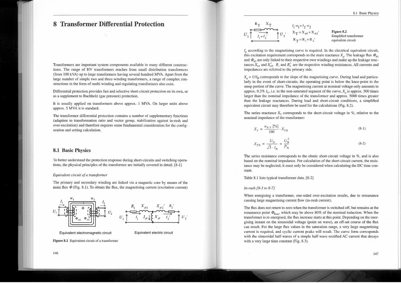
The primary and secondary winding are linked via a magnetic core by means of themain flux @ (Fig. 8.1). To obtain the flux, the magnetismg curreni(excitation current)
11
u, I ;
^
W
,, I
R T
\
by
Equivalent electromagnetic circuit
Figure 8.1 Equivalent circuit of a transformer
XT
W
Of
'02
^.
I=I'
I according to the magnetismg curve is required. In the electrical equivalent circuit,this excitation requirement corresponds to the main reactance X . The leakage flux @ Iand @, 2 are only linked to theirrespective own windings and make up the leakage rear-lances X, I and X, 2. Rj and Rz are the respective winding resistances. All currents andimpedances are referred to the primary side,
X = Un!ICOrresponds to the slope of the magnetismg curve. During load and particu-Iarly in the event of short-circuits, the operating point is below the knee-point in thesteep portion of the curve. The magnetismg current at nominal voltage only amounts toapprox. 0.2% IN, i. e. in the non-saturated segment of the curve* X is approx. 500 timeslarger than the nominal impedance of the transformer and approx. 5000 times greaterthan the leakage reactances, During load and short-circuit conditions* a simplifiedequivalent circuit may therefore be used for the calculations (Fig. 8.2).
The series reactance XT corresponds to the short-circuit voltage in %, relative to thenominal impedance of the transformer:
IfX-T t',XT' ~"T~ 100
2
_UN UNTN~ I^"N 'N
The series resistance corresponds to the ohmic short-circuit voltage in %* and is alsobased on the nontinalimpedance. For calculation onhe short-circuit current, the resis-tance may be neglected;it must only be considered when calculating the DC time con-slant
12
146
^.
; I'2
I '2'
I-w =I -wI~'j' 2"2
'T'Xoj"o2
RT =Rj+R2'
,, I
R
^
X
I I, , I
o2
Figure 8.2Simplified transformerequivalent circuit
81 Basic Physics
Equivalent electric circuit
X
R'
^.
2 I u, '
.XTN
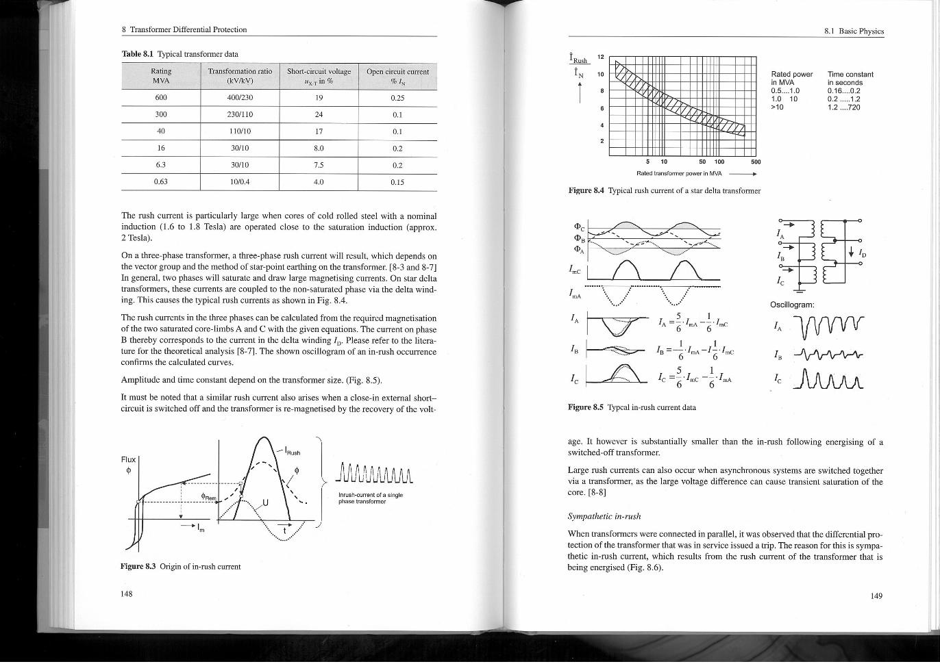
Table 8.1 lists typical transformer data. t8-21
In-rush 18-3 to 8-71
When energising a transfonner, one-sided overexcitation results, due to reinanancecausing large magnetising current flow (in-rush current).
The flux does notretum to zero when the transfonnerisswitchedoff, but remains arthe
reinanance point Ok. ,, which may be above 80% of the nominal induction. When thetransfonneris re-energised, the flux increase starts at this point. Depending on theener-gising instant on the sinusoidal voltage (point on wave), an off-set course of the fluxcan result. For the large flux values in the saturation range, a very large magnetismgcurrent is required, and cyclic current peaks will result. The curve form correspondswith the sinusoidal half-waves of a simple half-waye rectified AC currentthat decayswith a very large time constant(Fig. 8.3).
(82)
8 Transformer Differential Protection
Table 8.1 Typical hallsfomier data
Rating Tnnsfonnation ratio
MVA (kV/ICV)
4001230600
300
40
16
6.3
The rush current is particularly large when cores of cold rolled steel with a nominalinduction (1.6 to 1.8 Tesla) are operated close to the saturation induction (approx.2 Tesla).
On a three-phase transformer, a three-phase rush current will result, which depends onthe vectorgroup and the method of star-point earthing on the transformer. [8-3 and 8-7]In general, two phases willsaturate and draw large magnetismg currents. On star deltatransfonners, these currents are coupled to the non-saturated phase via the delta wind~ing. This causes the typical rush currents as shown in Fig. 8.4.
The rush currents in the three phases can be calculated from the required magnetisationof the two saturated core-limbsA and C with the given equations, The current on phaseB thereby corresponds to the current in the delta winding ID. Please refer to the liters-ture for the theoretical analysis [8-7]. The shown OScillogram of an in-rush occurrenceconfirms the calculated curves.
Amplitude and time constant depend on the transformer size. (Fig. 8.5).
It must be noted that a similar rush current also arises when a close-in externalshort-
circuitis switched off and the transformer is re-magnetised by the recovery of the volt
0.63
2301/10
Short-circuit voltage"x-T in %
19
110110
30/10
30/10
1010.4
24
Open circuit current%I
0.25
17
8.0
7.5
4.0
0.1
0.1
0.2
0.2
0.15
Rush
IN 10
I ,
Figure 8.3 Origin of in-rush current
6
148
4
5 10 50 too
Rated transformer power in MVA
Figure 8.4 Typical rush cument of a star delta transformer
2
JVV1'!11UVU^Innsh<linent ore singlephasehanslbrmer
Rated powerin MVA0.5. .,. 1.01.0 10>, O
8.1 Basic Physics
Time constantin seconds
0.16. ... 0.20.2 .....,. 2
I 2 .... 720
^
500
^.
age. It however is substantially smaller than the in-rush following energising of aswitched-off transfonner,
Large rush currents can also occur when asynchronous systems are switched togethervia a transfonner, as the large voltage difference can cause transient saturation of thecore. [8-8]
IA^
IB
+.
I
OScillogram:
IA
Sympathetic in-rush
When transformers wereconnected in parallel, it was observed that the differential pro-tortion of the transformer that was in service issued a trip. Thereason forthis is sympa-dietic in-rush current, which results from the rush current of the transfonner that is
being energised (Fig. 8.6).
+ I,
I
IC
8 Transfomier Differential Protection
Waveform:
*.-I
I
I2
figure 8.6 Sympathetic in-rush current
Transient currents:
The voltage drop resulting from the initial rush current across the source resistance ofthe in-feed affects the second transformer in parallel and causes the sympathetic in-rush current (12). The current from the system (IT) decays rapidly; however a currentstillcirculates between the two transformers due to the small damping (large time con-slant t= XIR of, he windings). t8-9 and 8-101
I,
I.I
... ~
....
Transformer
being closed
T2
Transformer
already closed
In-rush blocking
The in-rush currentflows into the protected object from a single side and appears as aninternal fault. The transfonner differential protection must therefore be stabilisedagainst this phenomenon. The large amount of second harmonic in the rush current wasalready used with conventional protection forthis purpose. The second harmonic is in-tored out of the differential current (operating current) by means of a filter, and is thenused as additional stabilising in the measuring bridge, When it was above approxi-mately 15% in relation to the 50 Hz fundamental, a very large additional stabilisingwas introduced to preventtripping. Other manufacturers compared the 100 and 50 Hzcomponents directly with a separate bridgecircuit, which then directly blocked the pro-rection, as it is now done in the software of numerical protection,
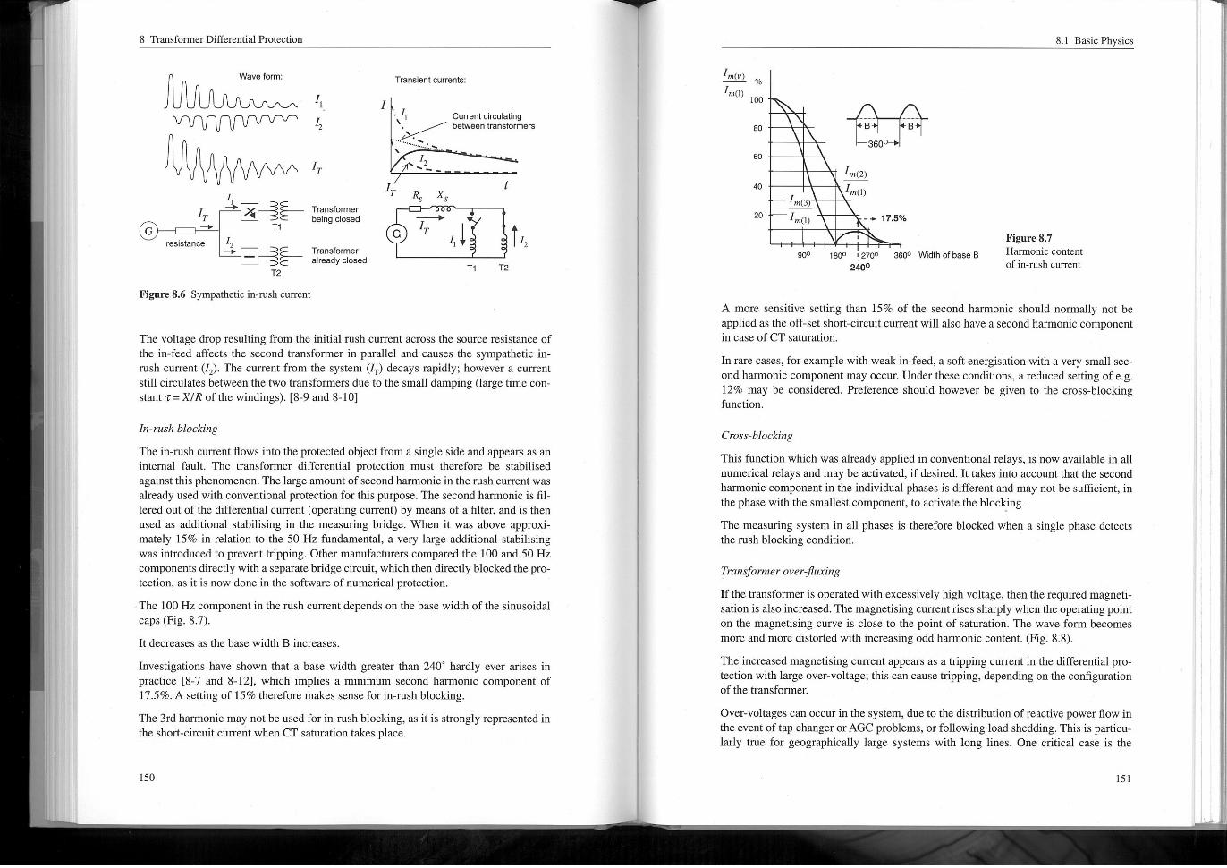
The 100 Hz componentin the rush current depends on the base width of the sinusoidalcaps (Fig. 8.7),
11 decreases as the base width B increases
Investigations have shown that a base width greater than 240' hardly ever arises inpractice 18-7 and 8-121, which implies a Thinimum second harmonic component of17.5%, A setting of 15% therefore makes sense for in-rush blocking.
The 3rd harmonic may not be used form-rush blocking, as iris strongly represented inthe short-circuit current when CT saturation lakes place,
Current circulatingbetween transformers
T
2~
R
G
X
^,.
T ,^ ^T,
t ,,T2
in(v)
in(I)
96
100^....^.
.LI.
80
60
40
B B
360
20
in(2)
L'in(I)...,r,
in(3)
in(I)
A more sensitive setting than 15% of the second harmonic should nomially riot beapplied as the off-setshort-circuit current will also have a second harmonic componentin case of CT saturation.
In rare cases, forexample with weak in-feed, a soft energisation with a very smallsec-ond harmonic component may occur. Under these conditions, a reduced setting ofe. g12% may be considered. Preference should however be given to the cross-blockingfunction.
900
-+ 17.5%
1800 ,2700
2400
8.1 BasicPhysics
3600 Width of base B
Cross-blocking
This function which was already applied in conventional relays, is now available in allnumerical relays and may be activated, ifdesired, intakes into accountthat the secondharmonic component in the individual phases is different and may not be sufficient, inthe phase with the smallest component, 10 activate the blocking.
The measuring system in all phases is therefore blocked when a single phase detectsthe rush blocking condition.
Figure 8.7Harmonic content
of in-rush current
Tram. ^former overtjl":ring
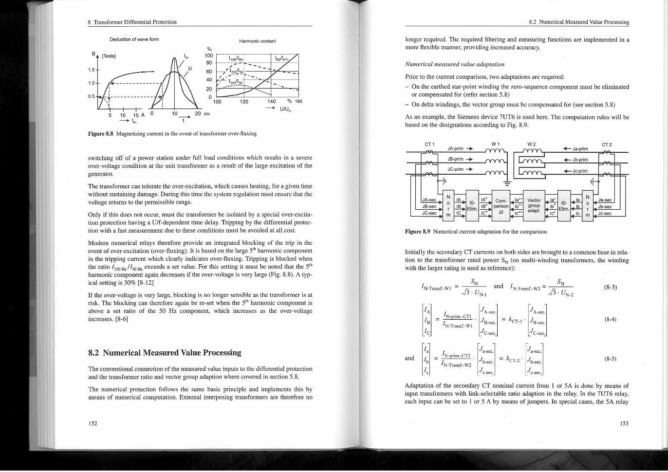
Ifthe transformer is operated with excessively high voltage, then the required magneti-sation is also increased. The magnetismg currentrises sharply when the operating pointon the magnetismg curve is close to the point of saturation. The wave fomi becomesmore and more distorted with increasing odd harmonic content, (Fig. 8.8).
The increased magnetismg current appears as a tripping current in the differential pro-tection with large over-voltage; this can cause tripping, depending on the configurationof the transformer.
Over-voltages can occur in the system, due to the distribution of reactive power flow inthe event of tap changer orAGC problems, or following load shedding. This is particu-Iarly true for geographicalIy large systems with long lines. One critical case is the
8 TnnsfomierDitferentialProtection
B
Deduction of wave han
,. 5
Frosial
1.0
0.5 :}---------....
5 10 15A^I
Figure 8.8 Magnetsingcurrent in the event of transformer over-fluxing
,
I,
II
%
1001150/1so
80
,125Q!!59 ,60I. ' '~.
40 1350/1so ~...,.,... .
20
o140120100^.
20 ms
switching off of a power station under fullload conditions which results in a severeover-voltage condition at the unittransfonner as a result of the large excitation of thegenerator.
The transfomiercan tolerate the overexcitation, which causes heating, for agiven timewithoutsustaining damage. During this time the system regulation must ensure that thevoltage returns to the permissible range.
Only if this does not occur, must the transfonner be isolated by a special overexcita-tion protection having a U/f-dependent time delay. Tripping by the differential pronec-tion with a fast measurement due to these conditions must be avoided at allcost.
Modem numerical relays therefore provide an integrated blocking of the trip in theevent of overexcitation (over-fluxing). mis based on the large 5'' harmonic componentin the tripping current which clearly indicates over-fluxing. Tripping is blocked whenthe ratio 1150H, /150.1, exceeds a set value. For this setting it must be noted that the 5'harmonic component again decreases ifthe over-voltage is very large (Fig. 8.8). A Iyp-ICal setting is 30% 18-121
If the over-voltage is very large, blocking is no longer sensible as the transformer is atrisk. The blocking can therefore again be re-set when the 5'' harmonic component isabove a set ratio of the 50 Hz component, which increases as the over-voltageincreases. [8-6]
U
o
Harmonic content
10^
1,011, T,
~ . ~
^ ..
7, 160
UN
8.2 Numerical Measured Value Processing
The conventional connection of the measured value inputs to the differential protectionand the transformer ratio and vector group adaption where covered in section 5.8.
The numerical protection follows the same basic principle and implements this bymeans of numerical coinpu, atton. External interposing transforrners are therefore no
longer required. The required filtering and measuring functions are implemented in amore flexible manner, providing increased accuracy.
Numerical meds"redva!"e adaptation
Priorto the current comparison, two adaptations are required:
- On the earthed star-point winding the zero-sequence component must be elininnatedor compensated for (refer section 5.8)
- On delta windings, the vector group must be compensated for (see section 5.8)
As an example, the Siemens device 7UT6 is used here. The computation rules will bebased on the designations according to Fig. 8.9.
8.2 Numerical Measured Value Processing
CT IJA-prim +
JB-prim +
JC"prim +
JA-sec
JB-sec
JC-sec
Wl
Figure 8.9 Numerical current adaptation forthe comparison
No
r
in
Initially the secondary CT curients on both sides are brought to a common base in rela-tion to the transformer rated power SN (on multi-winding transformers, the windingwith the larger rating is used as reference):
_ SNIN-Transf:-Wi ' ,-Tans-~ 15'UN-I
A A'sec.A'sec.
, ^LL. 'B-sec ~ 'CT-I' IB. sec.IBN-Tmnsf. -Wl
Jc. sec.C C-sec.
a. sec. a-sec.a
'b-sec ' 'CT-2' Ib. secIb
c-sec. c-secCj
Adaptation of the secondary CT nontinal current ftom I or 5A is done by means ofinporn'ansformers with link-selectable ratio adaption in the relay, In the 7UT6 relay,each input can be sello I or 5 A by means of jumpers. mspecial cases, the 5A relay
IA
IB
IC
10-Elim.
W2
IA* Coin-
IB* parisonA1IC'
^
<- Ja-prim
<-Jb hm
,.. Jo- rim
Ia** VectorIb** group
adapt.IC*,
CT2
18*
Ib
IC*
10-
Elim.
and
Sand IN. Transf. -W2' ^
. _,,. UN-2
IaN
o
r
in
, ^^I^..
IC
Ja-sec
Jb-sec
Jo-sec
N-Transf. W2
8 Transformer Differential Protection
inputmay also be applied to advantagewith a secondary CT currentof IA (refer exam-PIe 8-1).
The correction of the ratio deviation of, he primary CT rated current to the correspond-ing transfomier nominal currentis then done by the software.
Subsequently the zero sequence current component is eliminated. On the star-pointside this is absolutely essential if the winding star-point is earthed. If the star-point isriot earthed or on delta windings, this is riot necessary.
The zero sequence currentis: 10 = ~ ' (IA + IB ' IC)
The elimination in the phase currents is calculated with the following equations:
IA "A~'o 2-I-I AA
IB ' IB~10 Orin mainx-form I* -I 2 -I' IB* -I-I 2IC "C~'o ICIC
Thereafter, the vectorgroup can be considered (on three winding transformers there aretwo). The high voltage winding is always used as a reference according to the vectorgroup designation i. e. for example the star connected winding of aYd5 transfonner.
The three phase system of the low voltage winding(s)lags by the vector group numberin each phase.
The adaptation can be determined direcily from the connection of the winding. Alter-nativeIy, symmetrical components may be applied.
The following generalequation applies, whereby k is the vector group number*
I***
cos[k - 30'] cost(k + 4) - 30'1 cost(k-4) - 30 II** Icosj(k-4)- 30n cosjk- 30'l cos[(k+4)- 30 ] '
cos[("+4)-30'] cos[(k-4)-30n coslk 30*] I*I**
For aYd5-hansformeT with k = 5 the following resultis obtained:**
I-10 I
I**,_. I*Ib ~/;' I~" Ib** O I-I I
The measured values for comparison in the differential protection therefore arise as fol-lows:
I* I**A-A
I* , I**A-B
I* I**A-C
Thereby it must be rioted that currents flowing into the protected object are consideredwith a positive sense.
= - .
3
= - .2
3
8.2 Numerical Measured Value Processing
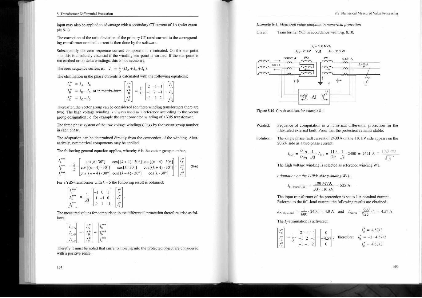
Example 8-I: Me@$14redvat"e @daptio" in ",, merita!projection
TransfomierYd5 in accordance with Fig, 8.10.Given:
SN= 100 MVA
UN2=20kV Yd5 UNj=110kV
W2 Wl3000/5 A 60011 A^
7621 A
,^
Figure 8.10 Circuitand data forexample 8-1
Wanted:
Solution:
';^;^ A1 ;^:
Sequence of computation in a numerical differential protection for theillustrated external fault. Proofthat the protection remains stable.
The singlephasefaul, current of 2400Aonthe 110kVside appearsonthe20 kV side as a two phase current:
IF-2 ' ' ' ~ 'IF. I ' ^ . - .2400 = 7621 A =
IA
2400 A^
The high voltage winding is selected as reference winding Wl,
Adaptation on the 110kV-side (winding \I),.
100 MVA
I' ' 110 kV
The inputtransformer of the protection is setto I A nonitnalcuiTent.Referred to the full-load current, the following results are obtained:
'A, B, c-sec ' ' . 2400 = 4.0A and IN, ,in = -- - 4 = 4.57 A
The 1, -elminnation is activated:
I* , 4,5713*I
therefore: Ib = -2 .4,5713
I , 4,5713I, = 4,5713I
IN-Tmnsf. -wj
I
= 525 A
3
2 -I-I
-I 2 -I
-I-I 2
o
-4.57 ,
o
8 Transformer Differential Protection
Adaptation on Ihe 20 kV-side Iwinding W2),.
100 MVAIN-Tnnsf. -W2 '
15 - 20 kV
The inputiransformer of the protection for winding 2 is set to 5 A,Referred to the full-load current, the following results are obtained:
I',','~"', ' ^666 ' 13200 113 , 4,411; A andIN, nn = - - 4.4 115 = 4,571/^ A
The 10-elimination is riotrequired on this side, and therefore riot activated.
The vector group adaptation forYd5 is as follows:
I** 4.57 115-10 I
I**=-'I- 0 ' 'Ib '7^' I~' 0 -4,571/g,I** O I-I o
The resultant tripping current (diff. current) therefore is:
I, A ^ I: +I, ** = 4,571/^-4,571/^ = O
I, _B ' If + I^' ^ -2 .4,571/^+2 .4,571/:; = O
I, _. ' I; + I:* ^ 4.57 1/5 -4,571/^ ^ O
The protection therefore remains stable,
An external interposing CT may in some cases be required. A typicalexample would be on a three winding transformer when one winding isonly rated for a very smallload, This is illustrated with the following prac-tical example.
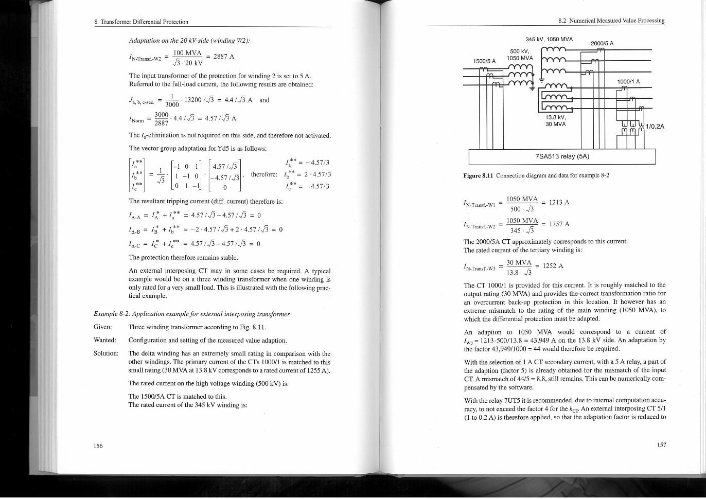
Ex@inPIe 8-2: Application exampleforexrem"linterposi"g troll. ^former
Three winding transformer according to Fig. 8.11.Given:
Configuration and setting of the measured value adaption.Wanted:
Solution: The delta winding has an extremely smallrating in comparison with theother windings, The primary current of the CTS 1000/1is matched to thissmallrating (30MVAa, 13.8 kVcorresponds to amtedcurrentof 1255A).
The rated current on the high voltage winding (500 kV)is:
The 1500/5A CT is matched to this.
filerated current ofthe 345 kV winding is:
= 2887 A
therefore:
I**, 4.57 3
I** , 2- 4.57 3
I** , 4.57 3
1500/5 A
345 kV, 1050 MVA
500 kV,1050 MVA
8.2 Numerical Measured Value Processing
7SA5,3 relay (5A)
Figure8.11 Connection diagram and data forexample 8-2
2000/5A
13.8 kV,30 MVA
N-Transf. -Wl
IN-Transf. -W2 '345 - 15
The 2000/5A CT approximately corresponds to this currentThe rated current of the tertiary winding is:
1252 A
1000/1 A
1050 MVA
500 - I^1050 MVA
30 MVA
N-Transf. .W3 ~ 13.8 .,/3 ~The CT 1000/1 is provided for this current. It is roughly matched to theoutput rating (30 MVA) and provides the correcttransfonnation ratio foran overcurrent back-up protection in this location. It however has anextreme mismatch to the rating of the main winding (1050 MVA), towhich the differential protection must be adapted.
An adaption to 1050 MVA would correspond to a current ofIw3 = 12/3.5001/3.8 = 43,949 A on the 13.8 kV side, An adaptation bythe factor 43,949/1000 = 44 would therefore be required.
With the selection of I A CT secondary current, with a 5 A relay, a part ofthe adap, ion (factor 5) is already obtained for the rimsmatch of the inputCT. A nitsmatch of 44/5 = 8.8, stillremains. This can be numerically coin-pensared by the software.
With the relay 7UT5 iris reconunended, due to internal computation accu-racy, to not exceed the factor4 for the k, , An external interposing CT 5/1(I to 0.2A)is therefore applied, so that the adaptation factor is reduced to
12/3 A
110.2A
1757 A
8 Transformer Differential Protection
8.815 = 1.76, The relay setting point "Primary rated current of the CT"must then be set to 1000.5.5 = 25,000A for the tertiary winding.
When defining the dimension of the interposing CT, it must be noted thatthe current levelis also very small during short-circuits. Referred 101000/1A, normuch more than ten times IN is to be expected, The internos-ing CT can therefore be coringured for 110.2 A raied current. With themulti-tap type 4AM22-7AA (see section 5.8, Fig. 5.33)the correct choicewould be 8 to 40 turns,
The above example illustrates the combination of CT, external interposing transfonneT,inputtransfonner and numeric compensation of the measured values. The interposingCT and the measuring input can be included in equation (8-4)to obtain the followingresult for the internal currentthatis processed in the relay (winding I as example):
IA
IBN-Internr. CT-c. I'Side 'N-relay-Ml-I 'N-Transf-Wl
IC C-sec.
IN-relay_Mj_lis the normnal current of the measuring input I of the relay. Generally, thenormnalcurrentofeach measuring inputis the same asthe relay nominal current. Ifthesecondary nominal current of the CTS on the transformer Leninnals are different, themeasuring inputs must however be matched by jumperselection.
In the above example, the Thismatch is used to advantage to provide the equivalent of a5/1interposing CT. The following results
IA A'sec
IB 18-sec.
IC, C-sec.
That means an adaptation to the rating 1050MVA.
Measuring algorithm
The adapted measured values are subjected to numeric evaluation according to the dif-ferentialprotection measuring principle.
The pick-up characteristic has three stages which is typical for numerical protection.Compared to generator protection, the basic pick-up threshold IDlFF>, and the slope ofthe first branch must have less sensitive settings as the magnetismg currents of thetransfomier* and ratio errors due to tap changers result in false differential currents.Adaptation of the transfomiation ratio in accordance with the tap changer tap positionwould in theory be possible, is however not implemented in practice due to theincreased complexity.
A cornmon setting value is 20% IN fortransfonners withouttap changer and up to 30%on transformers with tap changers having ^22% tap changer range.
N-InIC r. CT-rela side N-sec. -CT-I ^L
_ 0.2A IA 25,000AIA 5A 44,000A
A-sec
B-sec.
_ 1,00043,949
(87)
Op n
9
A-sec.
B-sec. ,
IC-,, C!
8
7
11 12^. ,^
7UT6,
6
5
4
IDIFF> -
o
3
2
8.2 Numerical Measured Value Processing
Rea n
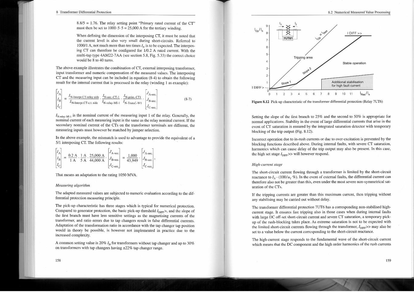
Figure 8.12 Pick-up characteristic of the transformer differential protection (Relay 7Ur6)
\^9
\oQ
Tripping area
s\o99
Setting the slope of the first brunch to 25% and the second to 50% is appropriate fornomial applications. Stability in the event of large differential currents that arise in theevent of CT saturation is ensured by the integrated saturation detector with temporaryblocking of the trip output (Fig. 8.12).
Incorrect operation due to in-rush currents ordue to over-excitation is prevented by theblocking functions described above. During internal faults, with severe CT saturation,harmonics which can cause delay of the trip output may also be present. In this case,the high set stage IDjFp>> will however respond.
High-current stage
The short-circuit current flowing through a transfonner is limited by the short-circuitreactance to I, - (1001, ,, %). In the event of external faults, the differential current cantherefore also notbe greater than this, even under the most severe nori-syrnmetricalsat-uralion of the CTS.
If the impping currents are greater than this maximum current, then tripping withoutany stabilising may be camed out without delay.
The transfonner differential protection 7UT6 has a corresponding nori-stabilised high-current stage. It ensures fast tripping also in those cases when during internal faultswith large DC off-set short-circuit current and severe CT saturation, a temporary pick-up of the rush-blocking takes place. As extreme saturation is riot to be expected withthe limited short-circuit currents flowing through the transformer, IDFF>> may also besello a value below the current corresponding to the short-circuit reactance.
The high-current stage responds to the fundamental wave of the short-circuit currentwhich meanstha. the DC component and the high order harmonics of the rush currents
'I.
^,,$;^
2
,,,FF
I DIFF >>
3 4 5
Stable operation
6
Additional stabilisation
for high foult current
7 8 9 10 11
8 Transfom, er Differential Protection
^re elmtinated. Including a securlty margin of 20%, a setting of approximately 60% ofIRUsh 1/2 may be applied as the maximum value of the fundamental wave in the rushcurrentis only approximately 50% of the rush current peak, The factory pre-setting is7-5'IN, Tmf, . It should be appropriate for most applications.
In case of internal transfomier faults near the terntinals, high fault currents may lead tofast CT saturation, This is always the case when smalltransfonners are connected to asystem with high short-circuit power.
Therefore, a fast momentary value processing high-set element is additionally pro-vided. It operates when two sannles exceed twice the IDjFF>> setting value, This ensuresultra high speed tripping before saturation occurs, The measuring principle was dis-cussed in section 4.2.2.
Earthf""!, dtff'eyen!iaip, otec, ion
During an earth-faulton an earthed transformer winding, short-circuitcurrents that cancause severe damage winnow. On the in-feed side the corresponding currents may berelatively smallifthe short-circuit currentis only linked by a few turns of the secondary winding.
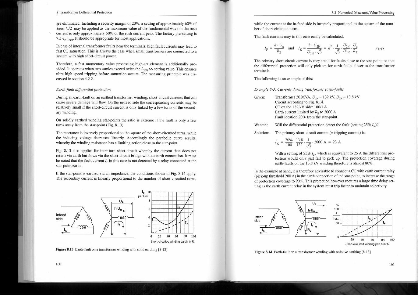
On solidly earthed winding star-points the ratio is extreme if the fault is only a fewturns away from the star-point(Fig, 8.13).
The reactance is inversely proportional to the square of the short-circuited turns, whilethe inducing voltage decreases linearly, Accordingly the parabolic curve results,whereby the winding resistance has a limiting action close to the star-point,
Fig. 8.13 also applies for inter-turn short-circuit whereby the current then does riotreturn via earth bun flows via the short-circuit bridge without earth connection. It mustbe noted that the fault current IF in this case is not detected by a relay connected at thestar-point earth.
If the star-point is eached via an impedance, the conditions shown in Fig. 8.14 apply.The secondary current is linearly proportional to the number of short-circuited turns,
Infeedside
while the current alitie in-feed side is inversely proportional to the square of the num-ber of short-circuited turns,
The fault currents may in this case easily be calculated:
h'U2N 2 I '2N'ah . UIK" "'~"'~IF' ' " U, ./; '75'UN i^;
The primary short-circuit currentis very small for faults close to the star-point, so thatthe differential protection will only pick up for earth-faults closer to the transformerterntinals.
The following is an example of this:
^.
IK
'18/1re 8.13 Earth-fault on a musformer winding with sond earthing t8-131
U,
h. Un
IF 10per Unit
IF
and
Ex@inPIe 8-3. . Currents during tram. ^fomiere@rthf""!ts
Transformer 20 MVA, U, N = 132 kV, U2N = 13.8 kVGiven:
Circuit according to Fig, 8.14.CT on the 132 kV side: 10011 A
Earth currentlimited by R to 2000AFaultloca, ion 20% from the star-point.
Will the differential protection detect the fault(setting 25% IN)?
Solution: The primary short-circuitcurrent(=tripping current)is:
8.2 Numerical Measured Value Processing
8
6
4
2
Wanted:
I
O 20 40 60 80 100
Short-circLiiled winding part h in %
,
I I
I
With a setting of 25% I, , which is equivalentt0 25 A the differential pro-toction would only just failto pick up. The protection coverage duringearth-faults on the 13.8 kV winding therefore is almost 80%,
In the example at hand, it is therefore advisable roconnect a CT with earth currentrelay(pick-up threshold 200A) in the earth connection of the star-point, to increase themrigeof protection coverage to 90%. This protection however requires a large time delay set-ting as the earth curTent relay in the system must trip faster to maintain selectivity.
I = ^--:----2000A = 23A
(8.8)
Infoedside
^.
IK
20 40 60 80 100
Short. circuitsd winding part h in %
Figure 8.14 Earth-fault on a transformer winding with resistive earthing 18-131
UR
h. U
IFRE
%100
Max
co ...
O~I,
I
I
I
I
I
IPI
IF
8 Transfonner Differential Protection
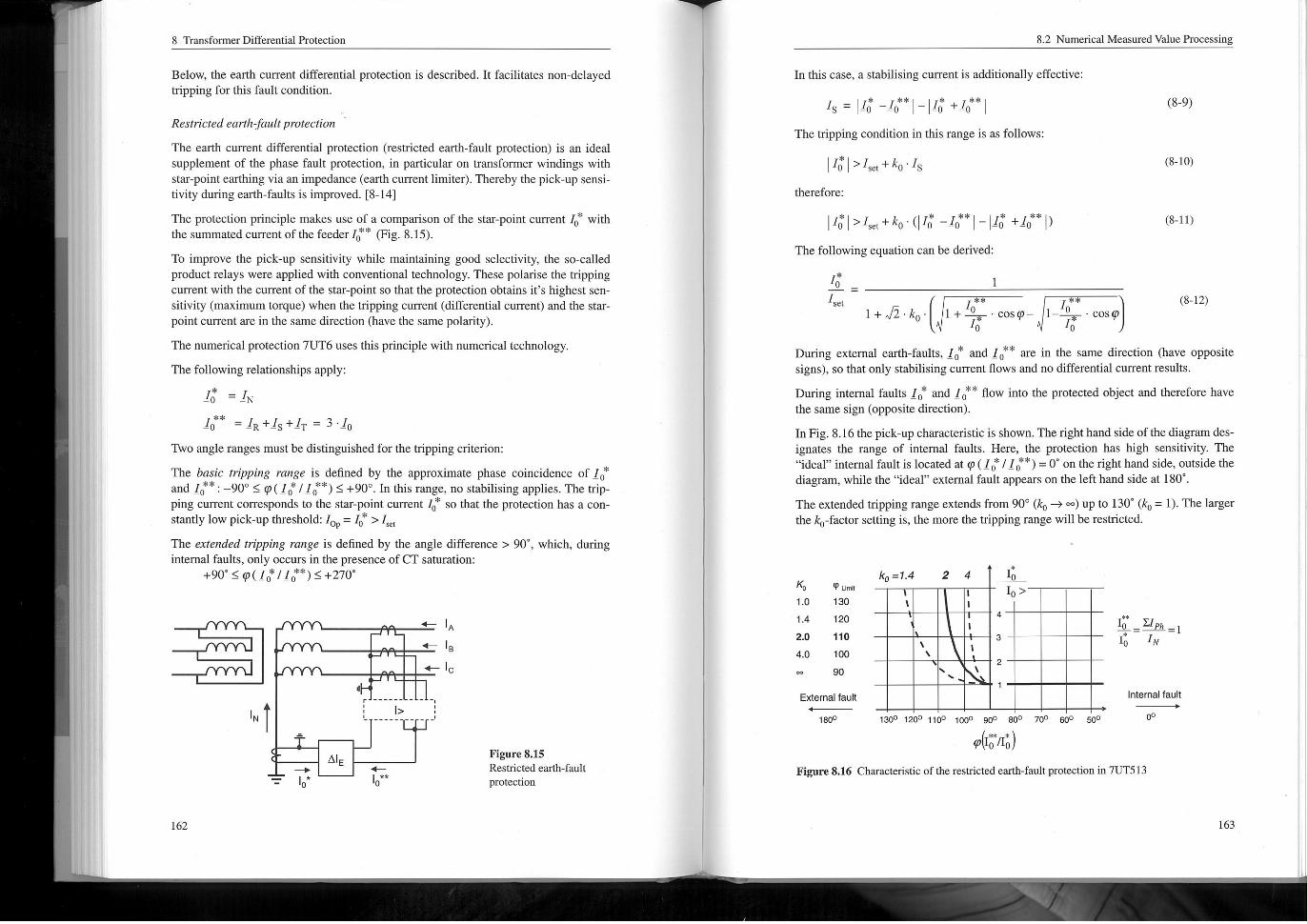
Below, the earth current differential protection is described. It facilitates non-delayedtripping for this fault condition.
Restric, ed earlhf""!IP, Diectio"
The earth current differential protection (restricted earth-fault protection) is an idealsupplement of the phase fault protection, in particular on transfonner windings withstar-point earthing via an impedance (earth currentlimiter). Thereby the pick-up sensi-tivity during earth-faults is improved. t8-141
The protection principle makes use of a comparison of the star-point current 1, * withthe summated current of the feeder^* (Fig. 8.15).
To improve the pick-up sensitivity while maintaining good selectivity, the so-calledproduct relays were applied with conventional technology, These polarise the trippingcurrent with the current of the star-point so that the protection obtains it's highest sen-sinvity (maximum torque) when the tripping current (differential current) and the star-point current are in the same direction (have the same polarity).
The numerical protection 7UT6 uses this principle with numerical technology.
The following relationships apply:
I* ,,10 "N
'0 ' IR+Is+IT ' 3'10
Two angle ranges must be distinguished for the tripping ctiterion:
The basic tripping range is defined by the approximate phase coincidence of 1, *and 1, ** : -90' ^ @(!j*/If*) S +90'. In this range, 00 stabilising applies, The inp-ping current corresponds to the star-point current 10 so that the protection has a con-sinntly low pick-up threshold: 10 ' 10 > I, et
The extended tripping range is defined by the angle difference > 90', which, duringinternal faults, only occurs in the presence of CT saturation:
+90' ^ @( If /If*) ^+270
In this case, a stabilising current is additionally effective:
I, . 11; -I, **I_I!; ,I, **I
The tripping condition in this range is as follows:
II;I^lad+k, ,I,
^" I
therefore:
1';I^I, **+k, -( I; _!,** I_11; ,^* I,
The following equation can be derived:
I*
'~ IA
' IB
,- IC
^
^
^.
r ------ - - -J
,
8.2 Numerical Measured Value Processing
I*
A1E
I>
^^
set
,-
During external earth-faults, 1, * and If* are in the same direction (have oppositesigns)* so that only stabilising current flows and 00 differential current results.
During internal faults 1, * and 1, ** flow into the protected object and therefore havethe same sign (opposite direction).
In Fig. 8.16 the pick-up characteristic is shown. The right hand side of the diagram des-ignates the range of internal faults. Here, the protection has high sensitivity. The"ideal"internal faultis located at @( 16'1 If*) = 0' on the right hand side, outside thediagram, while the "ideal" external fault appears on the left hand side at 180',
The extended impping range extends from 90'(k, ^ co) up to 130'(k, = I). The largerthe k, -factor setting is, the more the tripping range will be restricted.
I 00
,,,-*,-IF;:^-F;:I
Figure 8.15Restricted earth-fault
protection
(8-9)
(8-10)
1<61.0
(8-11)
I. 4
Q Lint
130
120
1.0
100
90
2.0
4.0
k0". 4
^
(8-12)
External fault
,. I. .2 4
^
^t:,";)Figure 8.16 Characteristic of the restricted earth-fault protection in 71TT513
1800
\
,
10 >
\
1300 1200 1100 1000 goo 800 700 600 500
4
\
3
\
..
..
..
..
2
10 ZIPh-- ^ I
'0 IN
Internal fault^
o0
8 Transfonner Differential Protection
K0=1.4
K0=4
,.. 140
20
100 80
Blocking
1.6
12
0.8
60
10* @('0*/10**)I **
.
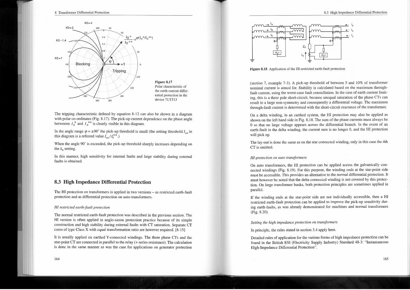
The tripping characierisiic defined by equation 8-12 can also be shown in a diagramwith polarco-ordinates(Fig. 8.17). The pick-up current dependence on the phase anglebetweenn If and 1, ** is clearly visible in this diagram.
In the angle range @ = =90' the pick-up threshold is small(the setting threshold I, ., inthis diagram is a referred value 1, ,, 11j**.)
When the angle 90'is exceeded, the pick-up threshold sharply increases depending onthe ko setting.
In this manner, high sensitivity for internal faults and large stability during externalfaults is obtained,
IP+I
Tripping
20
o
3.40
8.3 High Impedance Differential Protection
The HIProtection on transfonners is applied in two versions - as restricted earthprotection and as differential protection on auto-transformers.
Hlrestrictede@rthfa"It pratec, ton
The normal restricted earth-fault protection was described in the previous section. TheHl version is often applied in anglo-sayori protection practice because of its simpleconstruction and high stability during external faults with CT saturation. Separate CTcores of type Class X with equal transfomiation ratio are however required. [8-15]
It is usually applied on earthed Y-connected windings. The three phase CTS and thestar-point CT are connected in parallelto the relay (+ series resistance). The calculationis done in the same manner as was the case for applications on generator protection
Figure 8.17Polar characteristic of
the eamli-current differ-
enlial protection in thedevice 7UT513
^. A
+ 18
^C
Figure 8.18 Application of the Hlrestricted earth-fault protection
(section 7, example 7-3). A pick-up threshold of between 5 and 10% of transformernormnal current is aimed for. Stability is calculated based on the maximum through-fault current, using the worst-case fault constellation. In the case of earth currentlimit-ing, this is a three pole short-circuit* because unequal saturation of the phase CTS canresult in a large non-sy, Lui, etry and consequently a differential voltage, The maximumthrough-fault currentis deterimned with the short-circuit reactance of the transformer,
On a delta winding, in an earthed system, the Hl protection may also be applied asshown on the left hand side in Fig. 8.18. The sum of the phase currents must always beO so that no large voltage appears across the differential branch. In the event of anearth-fault in the della winding, the current sum is no longer O, and the Hl protectionwill pick up.
The lay-outis done the same as on the star connected winding* only in this case the 4thCT is ontitred.
8.3 High Impedance Differential Protection
, .
^" I
,- I
' Ib
+ IC
A1E'
Hl-protection on auto Ironstormers
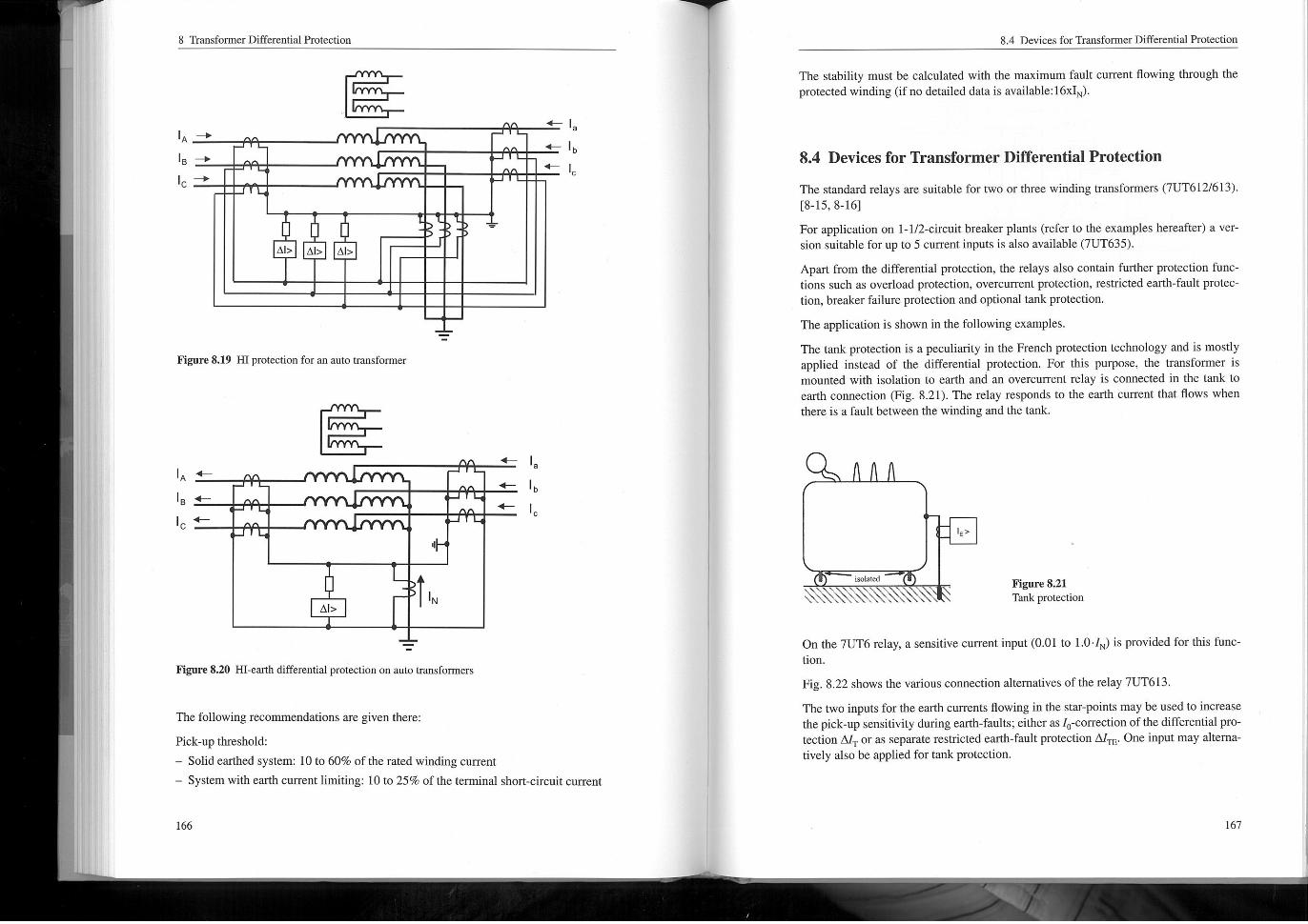
On auto transformers, the Hl protection can be applied across the galvanically con-nected windings (Fig. 8.19). For this purpose, the winding ends at the star-point sidemust be accessible. This provides an alternative to the normal differential protection. Itmust however be rioted that the delta connected winding is not covered by this protec-tion. On large transformer banks, both protection principles are sometimes applied inparallel.
If the winding ends at the star-point side are riot individually accessible, then a Hlresincied earth-fault protection can be applied to improve the pick-up sensitivity dur-ing earth-faults, as was already demonstrated for machines and normal transformers(Fig. 8.20).
Selling the high impedancepro!ecii0" o13tr@"$;formers
In principle, the rules stated in section 3.4 apply here.
Detailed rules of application forthe variousfonns of high impedance pro^Ciion can befound in the British ESl (Electricity Supply Industry) Standard 48-3: "InstantaneousHigh-Impedance Differential Protection".
8 Transformer Differential Protection
IA '
IB '
I+
I^^
A1> A1> A1>
Figure 8.19 HIProteciion for an auto nansformer
IA "~
IB '
I+
+I
'~ Ib
C<-
I^^
^
^
Figure 8.20 Hl-earth differential protection on auto transformers
The stability must be calculated with the maximum fault current flowing through theprotected winding (if no detailed data is available:16xlN).
The following recoinmiendations are given there:
Pick-up threshold:
- Solid earthed system: 10 to 60% of the rated winding current
- System with earth currentlirntting: 10 to 25% of the ternxinalshort-circuit current
^..
8.4 Devices for Transformer Differential Protection
The standard relays are suitable for two or three winding transfonners (7UT612/613).t8-15, 8-161
For application on I-1/2-circuit breaker plants (refer to the examples hereafter) a ver-sion suitable for up to 5 current inputs is also available (7UT635),
Apart from the differeniial protection, the relays also contain further protection func-lions such as overload pronection, overcurrent protection, restricted earth-fault pro^C"lion, breaker failure protection and optional tank protection,
The application is shown in the following examples.
The tank protection is a peculiarity in the French protection technology and is mostlyapplied instead of the differential protection, For this purpose, the transfonner ismounted with isolation to earth and an overcurrent relay is connected in the tank toearth connection (Fig. 8.21). The relay responds to the earth current that flows whenthere is a fault between the winding and the tank.
<-.
.
.
.
,-.
a
Ib
C.
<-
8.4 Devices for Tnnsfonner Differential Protection
^
^
.^I
^ ^.^\^^\isolated
On the 7UT6 relay, a sensitive currentinput(0.01 to 10.1, ) is provided for this func-
Fig. 8.22 shows the various connection alternatives of the relay 7UT613.
The two inputs forthe earth currents flowing in the star-points may be used to increasethe pick-up sensitivity during earth-faults; either as 1, -correction of the differential pro-rection A1 or as separate restricted earth-fault protection A1rE. One input may altema-tively also be applied fortank protection.
nori.
rig, re8.21Tank protection
8 Tnnsformer Differential Protection
YN ynO
49
(2)
I.
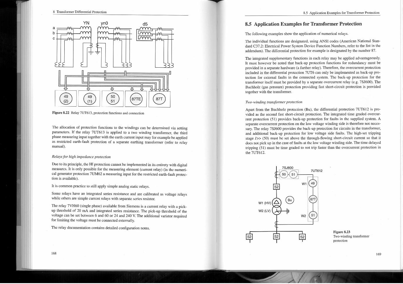
Figure 8.22 Relay 7UT613, protection functions and connection
O 0 6
The allocation of protection functions to the windings can be determined via settingparameters. If the relay 7UT613 is applied to a two winding transformer, the thirdphase measuring input together with the earth current input may forexample be appliedas restricted earth-fault protection of a separate earthing transfom, er (refer to relaymanual).
Relaysfor high impedanceprorectio"
Due to its principle, the HIProtection cannot be implemented in its entirety with digitalmeasures, Iris only possible for the measuring element(current relay) (in the numeri-cal generatorprotection 7UM62 a measuring input forthe restricted earth-fault protec-tion is available).
his common practice to still apply simple analog static relays.
Some relays have an integrated series resistance and are calibrated as voltage relayswhile others are simple current relays with separate series resistor.
The relay 7VH60 (single phase) available from Siemens is a currentrelay with a pick-up threshold of 20 IT^ and integrated series resistance. The pick-up threshold of thevoltage can be set between 6 and 60 or 24 and 240 V. The additional varistor requiredfor limiting the voltage must be connected externalIy.
The relay documentation contains detailed configuration notes.
87T
8.5 Appmcation Examples for TramformerProtection
The following examples show the application of numerical relays.
The individual functions are designated, using ANSI codes (American National Stari-dard C37.2: Electrical Power System Device Function Numbers, refer to the list in theaddendum). The differential protection for example is designated by the number 87.
The integrated supplementary functions in each relay may be applied advantageously11 must however be rioted that back-up protection functions for redundancy must beprovided in a separate hardware (a further relay). Therefore, the overcurrent protectionincluded in the differential protection 7UT6 can only be implemented as back-up pro-rection for external faults in the connected system, The back-up protection for thetransformer itself must be provided by a separate overcutrent relay (e. g. 7SJ600). TheBuchholz (gas pressure) protection providing fast short-circuit protection is providedtogether with the transfonner.
8.5 Application Examples for Transformer Protection
Two-wind^^g transformer protection
Apart from the Buchholz protection (Bu), the differential protection 7UT612 is pro-vided as the second fast short-circuit protection. The integrated lime graded overcurrent protection (51) provides back-up protection for faults in the supplied system. Aseparate overcurrent protection on the low voltage winding side is therefore nor neces-say. The relay 7SJ600 provides the back-up protection for circuits in the transformer,and additional back-up protection for low voltage side faults. The high-set trippingstage I>> (50) must be set above the through-flowing short-circuit current so that itdoes not pick up in the case offaults at the low voltage winding side. The time delayedtripping (51) must be time graded to riottrip faster than the overcurrent protection inthe 7UT612.
^ ^ ^Figure 8.23Two-winding transformerprotection
8 Transformer Differential Protection
Three-winding tm",$former protection
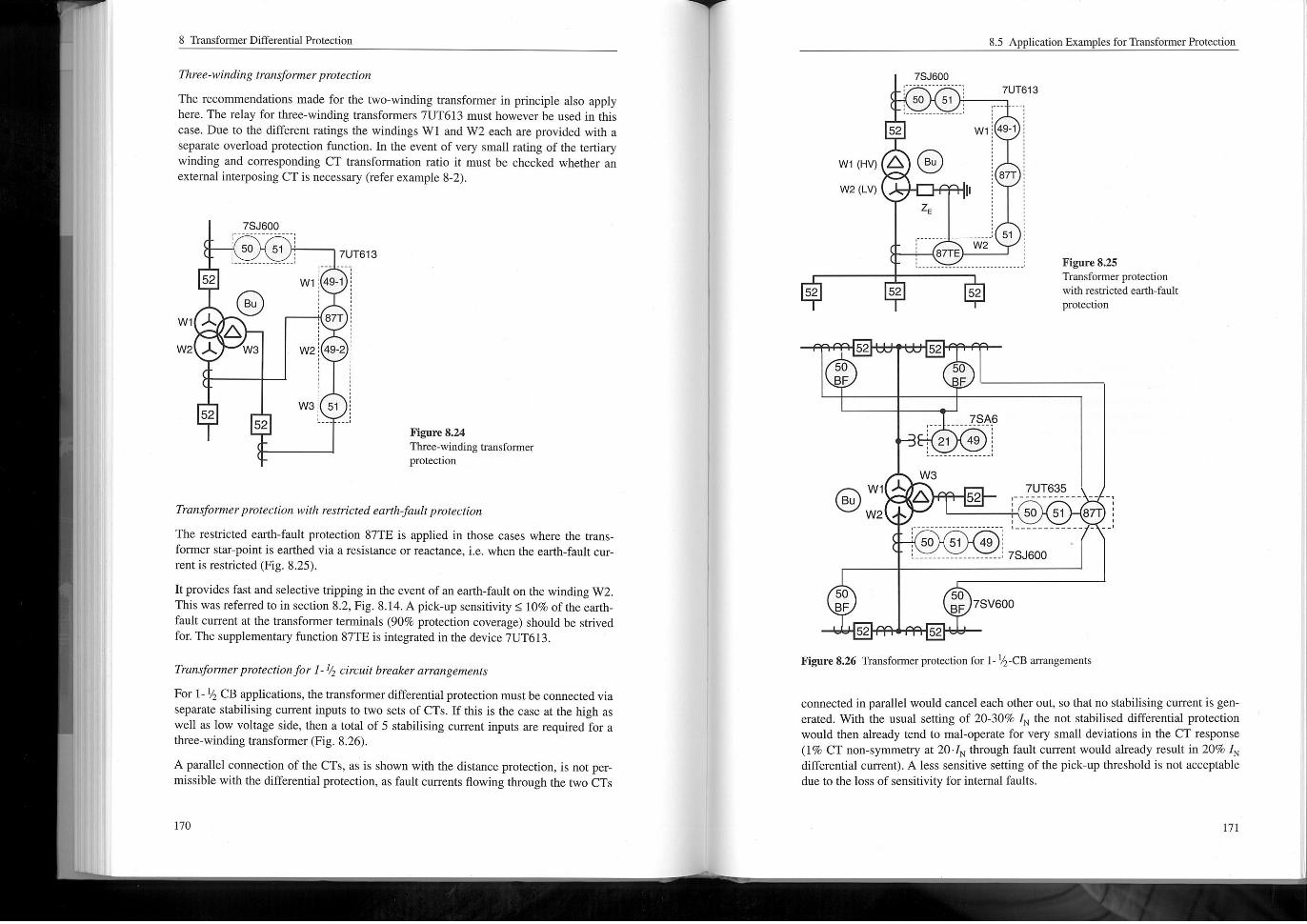
The recoilunendations made for the two-winding transformer in principle also applyhere. The relay for three-winding transfonners 7UT613 must however be used in thiscase. Due to the different ratings the windings Wl and W2 each are provided with aseparate overload protection function. In the event of very smallrating of the tertiarywinding and corresponding CT transfomiation ratio it must be checked whether anexternal interposing CT is necessary (refer example 8-2).
.
.
^^
Train's1'0rmerprotectio" wirh restricted earlh. faultp, oteciio"
The resincied earth-fault protection 87TE is applied in those cases where the trans-fonner star~point is earthed via a resistance or reactance, i. e. when the earth-fault current is restricted (Fig. 8.25).
It provides fast and selective tripping in the event of an earth-fault on the winding W2.This was referred to in section 8.2, Fig. 8.14. A pick-up sensitivity ^ 10% of the earth-fault current at the transformer tenntnals (90% protection coverage) should be strivedfor. The supplementary function 87TE is integrated in the device 7UT613.
Transformer projectionfor I- % circuitbre@ker@rin"geme"Is
For I-15 CB applications, the transformer differential protection must be connected viaseparate stabilising current inputs to two sets of CTS. If this is the case at the high aswell as low voltage side, then a Iotal of 5 stabilising current inputs are required for athree-winding transfonner (Fig. 8.26).
A parallel connection of the CTS, as is shown with the distance protection, is not per-Intssible with the differential protection, as fault currents flowing itrough the two CTS
^ ^
50
F
52
50
BF
Figure 8.26 Transformer protection for I-I^-CB amrigements
52
51 49 I_____.,.,...... I 7SJ600
52
connected in parallel would canceleach other out, so that no stabilising currentis gen-Grated. With the usual setting of 20-30% I, the not stabilised differential protectionwould then already tend to inal-operate for very small deviations in the CT response(I% CT non-symmetry at 20-1N through fault current would already result in 20% INdifferential current). A less sensitive setting of the pick-up threshold is not acceptabledue to the loss of sensitivity for internal faults.
7UT635
' 50
50
F
52
51
7SV600
- .,
87r I- -J
8 Tnnisfonner Differential Protection
On the high voltage side, a distance protection (21) is assumed, for providing back-upprotection. On the low voltage side this is provided by an overcurrent protection(50151). The overcurrent protection is connected to the hushing CTS of the transfonner.The breaker-failure protection on busbars with I I^ CB configuration is provided by adedicated relay for each CB as shown in the Figure. The winding currents are signiti-cant forthe overload protection (49). For the high voltage winding the integrated func-lion in the distance protection can therefore be used, while the corresponding functionin the overcurrent pTotection can be applied forthe low voltage.
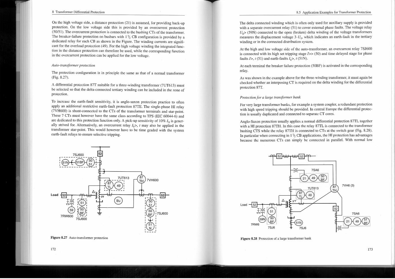
Auto-Iron, $former projection
The protection configuration is in principle the same as that of a nomialtransformer(Fig. 8.27).
A differential protection 87T suitable for a three-winding transformer (7UT613) mustbe selected so thatche delta-connected tertiary winding can be included in the zone ofprotection.
To increase the earth-fault sensitivity, it is anglo-sayori protection practice to oftenapply an additional restrictive earth-fault protection 87TE. The single-phase Hl relay(7VH600) is shunt-connected to the CTS of the transformer tenninals and star-point.These 7 CTS must however have the same class according to TPS (IEC 60044-6) andare dedicated to this protection function only. A pick-up sensitivity of 10% I is generally strived for. Alternatively, an overcurrent relay I, >, I may also be applied in thetransfonner sun-point. This would however have to be time graded with the systemearth-fault relays to ensure selective impping.
r
I 51N
7SJ600
51BF
Load 52
5051 I
52
- - .
The delta connected winding which is often only used for auxiliary supply is providedwith a separate overcurrent relay (51) to cover external phase faults. The voltage relayUE> (59N) connected to the open (broken) delta winding of the voltage transformersmeasures the displacement voltage 3-U, , which indicates an earth-fault in the tertiarywinding or in the connected distribution system.
Arthe high and low voltage side of the auto-transformer, an overcutrent relay 7SJ600is connected with its high set tripping stage I>> (50) and time delayed stage for phasefaults I>, 161) and earth-faults I, >, I(51N).
At each terminal the breaker failure protection (SOBF)is activated in the correspondingrelay.
As was shown in the example above forthe three-winding transformer, it must again bechecked whether an interposing CT is required on the delta winding for the differentialprotection 87T,
Yrn I 51
59 I 50
7RW600 .---
Y r ~~
7UT6,3F~ ~~~~~II 87
49 ITL
A
Figure 8.27 Auto-transformer protection
.- -----,
7SJ600
3Y
172
8.5 Application Examples for Transfomier Protection
Bu
87TH 7VH600
Projection ford large Iron. $fomerb@"k
For very large transformer banks, forexample a system coupler, aredundant protectionwith high speed tripping should be provided. In central Europe the differential pro^Clion is usually duplicated and connected to separate CT cores.
Anglo-Saxon protection usually applies a normal differential protection 87TL togetherwith a Hl protection 87TH. In this case the relay 87TL is connected to the transfonnerbushing CTS while the relay 87TH is connected to CTS at the switch gear (Fig, 8.28).In particularwhen connecting in I I^ CB applications, the HIProtection has advantagesbecause the numerous CTS can simply be connected in parallel. With normal low
5051
50BF
52
7SJ600
51N
. ----
8 Transfonner Differential Pronection
impedance protection, the connection to CTS of I I^ CB switch gearmust be applied toa 4 terniinaldifferentialproiection (7UT635)(compare previous examples).
A distance protection (21) is applied to both the high and low voltage side. The fasttripping stage is set to Teach about 80% into the transfonnerthereby providing fast pro-testion in this range. Iris also possible to apply a zone that reaches through the trans-fomer in combination with a directional comparison logic to obtain 100% protectioncoverage. In the latter case, the redundant differential protection may be omitted.
For the remaining protection functions the comments made in the previous exampleapply also here.
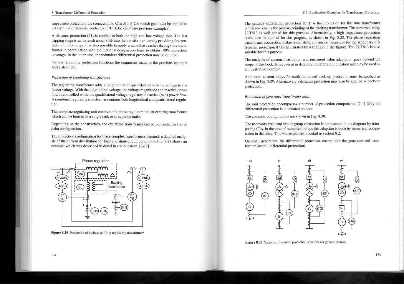
Protection of regulari"g tram. $10n"ers
The regulating transformer adds a longitudinal or quadrilateral variable voltage to thefeeder voltage. With the longitudinal voltage* the voltage magnitude and reactive powerflow is controlled while the quadrilateral voltage regulates the active (real) power now.A combined regulating transfonnerconiains both longitudinal and quadtilateralregula-tion.
The complete regulating unit consists of a phase regulator and an exciting transformerwhich can be housed in a single tank or in separate tanks,
Depending on the construction, the excitation transformer can be connected in star ordelta configuration.
The protection configuration for these complex transformers demands a detailed analy-sis of the current distribution for load and short-circuit conditions. Fig, 8.29 shows anexample which was described in detailin a publication. t8-171
A
50/50N
A I
I B"
I~~~~~~~~'~~-----,
5,151N
Phase regulator
87TP
r~~~~
The primary differential protection 87TP is the protection for the auto transfonnerwhich also covers the primary winding of the exciting transfonner. The numerical relay7UT613 is well suited for this purpose. Alternatively, a high impedance protectioncould also be applied for this purpose* as shown in Fig, 8.28. The phase regulatingtransfomier connection makes a star delta conversion necessary for the secondary dif-forential protection 87TS (illustrated by a triangle in the figure). The 7UT613 is alsosuitable for this purpose.
The analysis of current distribution and measured value adaptation goes beyond thescope of this book. mis covered in detailin the referred publication and may be used asan illustrative example.
Additional current relays for earth-faults and back-up protection must be applied asshown in Fig. 8.29. Alternatively a distance protection may also be applied as back-upprotection.
A1
ExcitingItransforrner
A
Figure 8.29 Protection of a phase shifting regulating transformer
-,
A
,
50N 51N
^^
A
50/50N
A
8.5 Application Examples for Transformer Protection
5,151N
87TS
51N
^
Protection of generatortr",,,$former Minirs
The unit protection encompasses a number of protection components. 17-11 Only thedifferential protection is elucidated on here,
The common configurations are shown in Fig. 8.30.
The necessary ratio and vector group correction is represented in the diagram by inter-posing CTS. In the case of numerical relays this adaption is done by numerical coinpu-tation in the relay. This was explained in detailin section 8.2.
On small generators, the differential protection covers both the generator and transformer (overall differential protection).
Figure 8.30 Various differential protection schemes for generator units
8 Transformer Differential Protection
^
. ... 8
A^.
... ..
:52:.. .,
01^,^IQ
*
^
G
*)
87G,' I^ 87r
*) same ratio as generator CTS
A
_ _ I
On larger units, a dedicated differential protection is provided for the generator, on theone hand for the higher sensitivity (10-15% instead of 25-30% IN), and on the otherhand for the selective indication of generator faults.
The variants by and c) are available for this purpose. The German Powersystem Relay-ing Coinimitee recoinments variant b),
On a unit with generator breaker, the variant d) may be applied, because the unittrans-former which also provides the auxiliary supply may be started and operated sepa-rarely.
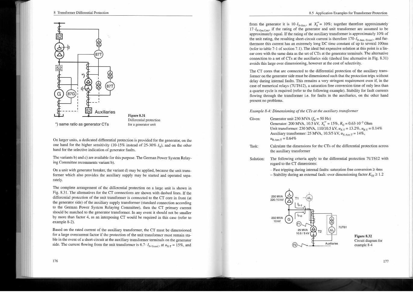
The complete arrangement of the differential protection on a large unit is shown inFig. 8.31. The alternatives for the CT connections are shown with dashed lines. If thedifferential protection of the unit transfonner is connected to the CT core in front (atthe generator side) of the auxiliary supply transfonner (standard connection according10 the Gemian Power System Relaying Coinimttee), then the CT primary currentshould be matched to the generator transfonner. In any eventit should not be smallerby more than factor 4, as an interposing CT would be required in this case (refer toexample 8-2).
Based on the rated current of the auxiliary transformer, the CT must be dimensionedfor a large overcurrent factor if the protection of the unittransfonner must remain sta-ble in the event of a short-circuit at the auxiliary transformer ternxinals on the generatorside. The current ilowing from the unit transfomier is 6.7. IN. T, ,, r. , arux. T ' 15%, and
52 AuxiliariesFigure831Differential protectionfor a generator unit
from the generator it is 10.1N. 0, ,., at XII"= 10%; together therefore approximately17.1N_G. ,. u, i, , if the rating of the generator and unit transformer are assumed to beapproximately equal. Ifthe rating of the auxiliary transformer is approximately 10% ofthe unit rating, the resulting short-circuit current is therefore 170.1N. A, ,.. T, ,,, f, and furthennore this current has an extremely long DC time constant of up to several looms(refer to table 7-1 of section 7.1). The ideal but expensive solution arthis point is a Iin-earcore with the same data as the set of CTS at the generatorterininals, The alternativeconnection to a set of CTS at the auxiliaries side (dashed line alternative in Fig. 8.31)avoids this large over dimensioning, however at the cost of selectivity.
The CT cores that are connected to the differential protection of the auxiliary trans-former on the generatorside must be dimensioned such that the protection trips withoutdelay during internal faults. This remains a very stringent requirement even if, in thecase of numerical relays (7UT612), a saturation free conversion time of only less thana quarter cycle is required (refer to the following example), Stability for fault currentsflowing through the transformer i. e. for faults in the auxiliaries, on the other handpresent no problems,
Example 8-4: Dimensioning of the CTS at the @,, tilia, y tm"^former
Generatorunit230 MVA (fN = SOHz)Given:
Generator: 200MVA, 10.5 kV, XI, " = 15%, R, = 0.63-10'' OhmUnittransfonner: 230 MVA, 110110.5 kV, "x. T = 13.2%, "R. T = 0.14%Auxiliary transfonner: 25 MVA, 10,515 kV* "x. AunT ' 14%,MR. A",. T ' 0.64%
Calculate the dimensions for the CTS of the differential protection acrossthe auxiliary transfomier
Solution: The following ctiteria apply to the differential protection 7UT612 withregard to the CT dimensions:
Fasttripping during internal faults: saturation free conversion ^ 4msStability during an external fault: over dimensioning factor KTF ^ 1.2
8.5 Application Examples for Transformer Protection
Task:
^^.
,
,
^
^o
,,
@
^C^
e^^
.
.
,
Figure 8.32Circuit diagram forexample 8-4

8 Tnnsformer Differential Protection
Formtemalfaults the ctitical case is a short-circuit at the terniinals on thegeneratorside (F1):
Rated current of the generator:
SN tMVAj. 10 200 - 10
UN[kV]-/; 10.5'/^
Short-circuit current from the generator:
I, _G ' '~~ ' ~" ' '11<A
_ UN. c tkv ,
IN-c ,
N-G ~ SN. 0 [MVA]
X =-^^-X = -0,551G~ 100 N"~ 100
^^^
DC time constant:
T-G_ G _ 0,083Ro co"0 314-0.63.10~3
Rated current ofthe unittransfonner:
10 230-10
11 ICJ\
10.5
200= 0,551 Q
IN-T ,UN[kV]-/^ 10.5. /^
Short-circuit current from the unittransfonner:
SN_T [MVA]
= 0,083 SL
'.' "N_T _ 1.1- 12,6 _IF-T, , , ,,,r-T "x. T['] ~ 0.132 -
x =N-T ~
= 0.42 s
^^
UN_T [kV ] _ 10.5 _ o, 48'SN. T[MVA] ~ 230 ~
XT ' ~"'X _ , _,.
RT ' ^ 'XN. T = -'- .0.48 = 0.67-10~ Q
12.6 1<A
DC time constant:
105 ICA
The corresponding equivalent time constant is calculated with the equa-lion (523) in section 5.7:
IF-G ' 'c 'IF-T ' TT _ 81- 0.42 + 105 - 0.3081 + 105IF-G ' IF-T
The over dimensioning factor for 4ms saturation free conversion isobtained with the equations 5-21 and 5-22, in section 5.7, The value isextracted from the corresponding diagram in Fig. 5.14: KTF = 0.75
The rated current of the auxiliary transfonneris:3
SN. AunT [MVA]. 10 25 - 10
10.5 , I^UN [kV]- 15
Currenttransformers of the type 5P with a ratio 2000/1 and 10 VA ratedburden are chosen. According 10 the manufacturers data, the internal burden is approximately 20%, The connection cables plusrelay havea burdenof< I VA.
_LT XT _ 0063---^-^
RT co"T 314-0,67.10~'
T=
The total current is:
IF'IF_G +IF. T' 81 + 105 = 186 kA
048 = 0,063 SL
8.5 Application Examples for Tnnsformer Protection
IN-Aux-T '
= 0.30 s
The required operaiional accuracy limit factor is:
ALF' = K -^ = 0.75-^ = 70
= 0.35 s
To check the stability during through fault currents, the fault F2 must beanalysed:
The short-circuit current is estimated by neglecting the source imped-ances:
1380 A
IF-Aux-T '"X-AunTl'l
The resulting operational accuracy limit factor taking into considerationthe required over-dimensioning factor KTF = 1.2 is as follows:
F-Aux-T _ALF' = KTF
N-CT
Therefore the ctiterion for internal faults must be considered.
And finally the required accuracy limit factoris obtained:
'i"connected ,_ 2+I _
' N-AMx-T 1.1 - 1.38
0.14
ALF ='N"rated 10+I ~
A value in = 20 is chosen and specified:CT 2000/1, 5P20,10 VA, P, < 20%
11 ICA
1.2- - = 6.6