zero deadleg t-valve, manually operated, stainless steel ... · † certification of conformity for...
TRANSCRIPT
3234
p. 1/10www.burkert.com
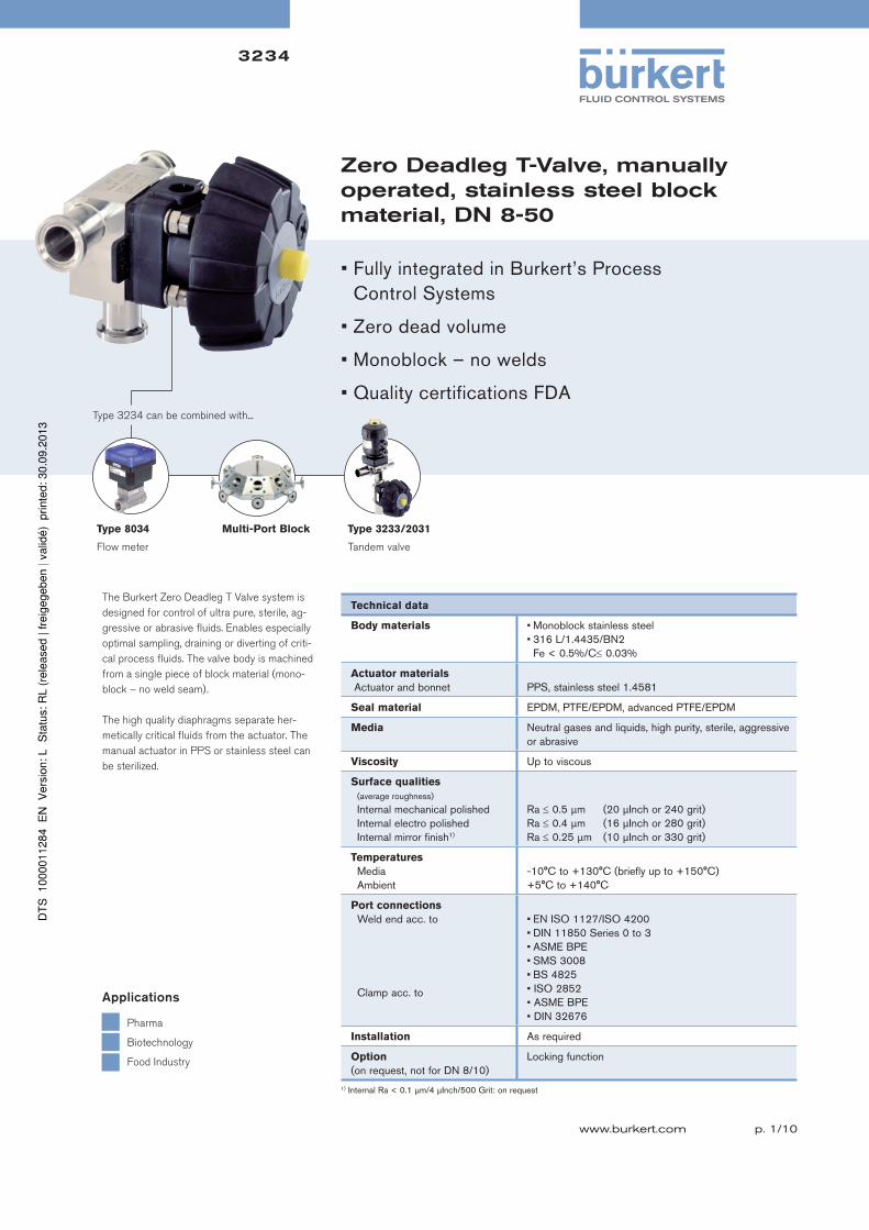
Zero Deadleg T-Valve, manually operated, stainless steel block material, DN 8-50
The Burkert Zero Deadleg T Valve system is
designed for control of ultra pure, sterile, ag-
gressive or abrasive fluids. Enables especially
optimal sampling, draining or diverting of criti-
cal process fluids. The valve body is machined
from a single piece of block material (mono-
block – no weld seam).
The high quality diaphragms separate her-
metically critical fluids from the actuator. The
manual actuator in PPS or stainless steel can
be sterilized.
Type 8034
Flow meter
Multi-Port Block Type 3233/2031
Tandem valve
Type 3234 can be combined with...
Pharma
Biotechnology
Food Industry
Applications
• Fully integrated in Burkert’s Process Control Systems
• Zero dead volume
• Monoblock – no welds
• Quality certifications FDA
Technical data
Body materials • Monoblock stainless steel• 316 L/1.4435/BN2 Fe < 0.5%/C 0.03%
Actuator materials
Actuator and bonnet PPS, stainless steel 1.4581
Seal material EPDM, PTFE/EPDM, advanced PTFE/EPDM
Media Neutral gases and liquids, high purity, sterile, aggressive or abrasive
Viscosity Up to viscous
Surface qualities
(average roughness)
Internal mechanical polished Internal electro polished Internal mirror finish1)
Ra 0.5 µm (20 µInch or 240 grit)Ra 0.4 µm (16 µInch or 280 grit)Ra 0.25 µm (10 µInch or 330 grit)
Temperatures
Media Ambient
-10°C to +130°C (briefly up to +150°C) +5°C to +140°C
Port connections
Weld end acc. to
Clamp acc. to
• EN ISO 1127/ISO 4200• DIN 11850 Series 0 to 3• ASME BPE• SMS 3008• BS 4825• ISO 2852 • ASME BPE• DIN 32676
Installation As required
Option
(on request, not for DN 8/10)Locking function
1) Internal Ra < 0.1 µm/4 µInch/500 Grit: on request
3234
p. 2/10
Technical data, continued
Specifications
Orifice
diaphragm
[mm]
Kv value water
(m3/h)
Max. operating pressure (medium)
for seal material
EPDM and PTFE/EPDM [bar]
8 1.0 10
10 1.0 10
15 6.0 10
20 11.0 10
25 16.0 10
40 29.0 10
50 50.0 101)
1) Max. operating pressure 7 bar for bonnet and manual actuator in PPS
Orifice DN 65, DN 80 and DN 100 on request
Various other Clamp and Sterile threaded end connection combination are available, please consult for advice.

3234
p. 3/10
Approvals/certifications
• Certification of Conformity for Raw Material EN-ISO 10204 3.1
• Attestation of compliance with the order EN-ISO 10204 2.1
• Test report EN-ISO 10204 2.2
• 3A Certification on request
• Certification of Conformity for Pickling and Electropolishing Processes
• Certification of Conformity for the Surface Quality DIN4762-DIN4768-ISO/4287/1
• Attestation of compliance with FDA CFR No. 21.177.1550 for PTFE/EPDM and advanced PTFE/EPDM and 21.177.2600 for EPDM
• USP CLASS VI certification for EPDM, PTFE and advanced PTFE diaphragm
• Test Certification and Conformity Certification for the Final Assembly of Diaphragm Valves
• ISO 9001 Certification
Note: Retrospective manufacturing certification for process diaphragm valves can not be made, therefore please notify when ordering.
Materials
Example of available diaphragm materials
Developed to handle the unique challenges of hygienic and sterile applications, Bürkert offers diaphragms with precise material formula and physical
tolerances. Bürkert diaphragms are available in a wide range of materials which have been proven in food & beverage, biotechnology, pharmaceutical
and cosmetic industry applications. Diaphragms are tested during development and production to ensure reliability in critical processing environments.
• EPDM (Ethylene Propylene Rubber)
• PTFE/EPDM
• Advanced PTFE/EPDM
• FKM
• PTFE/FKM
• NBR
PPS or 316L stainless steel
PPS or 316L stainless steel
EPDM, PTFE/EPDMadvanced PTFE/EPDM
Stainless steel316L/1.4435/BN2 Fe<0.5%
316L stainless steel

3234
p. 4/10
Dimensions [mm]
Welded body acc. to EN ISO 1127/ISO 4200
Orifice ØD1 s1 ØD2 s2 A B C E F G H I
8 17.2 1.6 17.2 1.6 78.0 20 49.00 20 60 29 18 8.021.3 1.6 17.2 1.6 78.0 20 51.05 20 64 34 21 11.026.9 1.6 13.5 1.6 88.0 25 53.85 20 70 38 23 13.033.7 2.0 13.5 1.6 88.0 25 56.85 20 76 45 26 16.042.4 2.0 13.5 1.6 88.0 25 61.20 20 84 52 29 19.042.4 2.0 17.2 1.6 88.0 25 61.20 20 84 52 29 19.048.3 2.0 13.5 1.6 88.0 25 64.15 20 90 57 31 21.0
15 13.5 1.6 13.5 1.6 93.0 20 52.05 20 70 27 17 4.517.2 1.6 13.5 1.6 93.0 20 53.90 20 70 31 18 4.521.3 1.6 21.3 1.6 93.0 20 55.95 20 71 35 21 6.526.9 1.6 21.3 1.6 103.0 25 58.75 20 78 42 25 11.533.7 2.0 21.3 1.6 103.0 25 62.75 20 82 47 28 14.542.4 2.0 21.3 1.6 103.0 25 67.10 20 91 56 32 18.548.3 2.0 13.5 1.6 103.0 25 69.05 20 97 61 34 20.548.3 2.0 21.3 1.6 103.0 25 69.05 20 97 63 35 21.560.3 2.0 13.5 1.6 113.0 30 76.05 20 109 71 38 24.560.3 2.0 21.3 1.6 113.0 30 76.05 20 109 72 38 24.576.1 2.0 13.5 1.6 113.0 30 83.95 20 125 85 44 30.576.1 2.0 21.3 1.6 113.0 30 83.95 20 125 85 44 30.588.9 2.3 13.5 1.6 113.0 30 90.05 20 140 99 52 38.5
20 26.9 1.6 26.9 1.6 114.0 25 70.25 25 88 42 24 6.033.7 2.0 26.9 1.6 114.0 25 73.25 25 94 48 28 10.042.4 2.0 26.9 1.6 114.0 25 78.60 25 102 57 33 15.048.3 2.0 26.9 1.6 114.0 25 80.55 25 108 63 35 17.060.3 2.0 26.9 1.6 124.0 30 86.55 25 121 74 40 22.076.1 2.0 26.9 1.6 124.0 30 94.45 25 136 86 45 27.0
25 33.7 2.0 33.7 2.0 124.5 25 78.55 25 98 53 33 13.042.4 2.0 33.7 2.0 124.5 25 82.90 25 107 62 38 18.076.1 2.0 33.7 2.0 134.5 30 99.75 25 142 94 52 32.0
40 42.4 2.0 42.4 2.0 152.0 25 97.00 25 122 62 37 8.448.3 2.0 48.3 2.0 152.0 25 99.95 25 128 68 41 12.460.3 2.0 48.3 2.0 162.0 30 105.95 25 140 82 48 19.476.1 2.0 48.3 2.0 162.0 30 113.85 25 155 97 55 26.4
50 60.3 2.0 60.3 2.0 188.0 30 120.15 30 154 82 48 12.576.1 2.0 60.3 2.0 188.0 30 128.05 30 172 100 56 20.588.9 2.3 60.3 2.0 188.0 30 134.15 30 183 110 61 25.5
For all actutors
Orifice J ØK
8 48 34
15 77 85
20 84 85
25 86 85
40 105 114
50 120 114

3234
p. 5/10
Dimensions [mm], continued
Welded body acc. to ASME BPE
Orifice ØD1 s1 ØD2 s2 A B C E F G H I
15 12.70 1.65 12.70 1.65 93.0 20 51.60 20 70 27 13.5 0.0
19.05 1.65 12.70 1.65 103.0 20 54.78 20 70 31 18.5 5.0
25.40 1.65 12.70 1.65 103.0 20 57.95 20 75 40 24 10.5
38.10 1.65 12.70 1.65 103.0 25 64.30 20 88 54 31 17.5
50.80 1.65 12.70 1.65 113.0 30 71.65 20 100 64 35 21.5
63.50 1.65 12.70 1.65 113.0 30 78.80 20 113 73 38 24.5
76.20 1.65 12.70 1.65 113.0 30 84.35 20 125 85 44 30.5
20 19.05 1.65 19.05 1.65 114.0 25 66.28 25 85 36 18 0.0
25.40 1.65 19.05 1.65 114.0 25 69.45 25 90 40 24 6.0
38.10 1.65 19.05 1.65 114.0 25 75.80 25 98 53 31 13.0
50.80 1.65 19.05 1.65 124.0 30 82.15 25 111 66 37 19.0
63.50 1.65 19.05 1.65 124.0 30 88.50 25 123 75 40 22.0
76.20 1.65 19.05 1.65 124.0 30 94.85 25 137 87 45 27.0
25 25.40 1.65 25.40 1.65 124.5 25 74.75 25 95 42 26 6.0
38.10 1.65 25.40 1.65 124.5 25 81.10 25 103 58 36 16.0
50.80 1.65 25.40 1.65 134.5 30 87.45 25 120 75 44 24.0
63.50 1.65 25.40 1.65 134.5 30 93.80 25 130 83 48 28.0
76.20 1.65 25.40 1.65 134.5 30 100.15 25 142 94 52 32.0
40 38.10 1.65 38.10 1.65 152.0 25 95.20 25 121 58 35 6.4
50.80 1.65 38.10 1.65 162.0 30 101.55 25 131 72 43 14.4
50 50.80 1.65 50.80 1.65 188.0 30 115.75 30 145 71 42 6.5
63.50 1.65 63.50 1.65 188.0 30 122.10 30 158 86 50 14.5
For all actutors
Orifice J ØK
8 48 34
15 77 85
20 84 85
25 86 85
40 105 114
50 120 114

3234
p. 6/10
Dimensions [mm], continued
Welded body acc. to DIN 11850 Series 0 and 2
Orifice ØD1 s1 ØD2 s2 A B C E F G H I
Series 0
08 6.0 1.0 6.0 1.0 78.0 20 43.0 20 60 17 6.5 0.0
40.0 1.5 6.0 1.0 88.0 25 60.5 20 83 51 29 19.0
40.0 1.5 10.0 1.0 88.0 25 60.5 20 83 51 29 19.0
52.0 1.5 6.0 1.0 98.0 30 66.5 20 95 60 32 22.0
25 28.0 1.5 28.0 1.5 124.5 25 76.2 25 95 46 29 9.0
52.0 1.5 28.0 1.5 134.5 30 88.2 25 117 71 42 22.0
40 28.0 1.5 34.0 1.5 152.0 25 90.3 25 122 58 32 3.4
52.0 1.5 34.0 1.5 162.0 30 102.3 25 132 75 45 16.4
50 52.0 1.5 52.0 1.5 188.0 30 116.5 30 147 73 43 7.5
Series 2
15 19.0 1.5 19.0 1.5 93.0 20 54.9 20 70 33 20 6.5
23.0 1.5 19.0 1.5 103.0 20 56.9 20 72 37 22.5 8.5
35.0 1.5 19.0 1.5 103.0 25 62.9 20 84 50 29 14.5
41.0 1.5 19.0 1.5 103.0 25 65.9 20 91 56 32 18.5
20 23.0 1.5 23.0 1.5 114.0 25 68.4 25 88 42 21 3.0
35.0 1.5 23.0 1.5 114.0 25 74.4 25 95 50 29 11.0
41.0 1.5 23.0 1.5 114.0 25 77.4 25 101 56 32 14.0
25 29.0 1.5 29.0 1.5 124.5 25 76.7 25 98 48 30 10.0
40 41.0 1.5 41.0 1.5 152.0 25 96.8 25 121 62 37 8.4
50 53.0 1.5 53.0 1.5 188.0 30 117.0 30 147 74 44 8.5
For all actutors
Orifice J ØK
8 48 34
15 77 85
20 84 85
25 86 85
40 105 114
50 120 114

3234
p. 7/10
Dimensions [mm], continued
Welded body acc. to SMS 3008
Orifice ØD1 s1 ØD2 s2 A B C E F G H I
25 25.0 1.2 25.0 1.2 124.5 25 75.0 25 95 43 27 7.0
38.0 1.2 25.0 1.2 124.5 25 81.5 25 105 59 36 16.0
51.0 1.2 25.0 1.2 134.5 30 88.0 25 118 72 42 22.0
40 38.0 1.2 38.0 1.2 152.0 25 95.6 25 121 58 35 6.4
51.0 1.2 38.0 1.2 162.0 30 102.1 25 131 73 44 15.4
50 51.0 1.2 51.0 1.2 188.0 30 116.3 30 147 73 43 7.5
For all actutors
Orifice J ØK
8 48 34
15 77 85
20 84 85
25 86 85
40 105 114
50 120 114
3234
p. 8/10
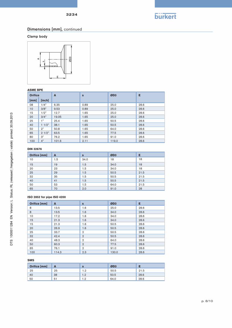
Dimensions [mm], continued
Clamp body
ASME BPE
Orifice A s ØD3 E
[mm] [inch]
08 1/4” 6.35 0.89 25.0 28.610 3/8” 9.53 0.89 25.0 28.615 1/2” 12.7 1.65 25.0 28.620 3/4” 19.05 1.65 25.0 28.625 1” 25.4 1.65 50.5 28.640 1 1/2” 38.1 1.65 50.5 28.650 2” 50.8 1.65 64.0 28.665 2 1/2” 63.5 1.65 77.5 28.680 3” 76.2 1.65 91.0 28.6100 4” 101.6 2.11 119.0 28.6
DIN 32676
Orifice [mm] A s ØD3 E
10 1.5 34.0 18 18
15 19 1.5 34.0 1820 23 1.5 34.0 1825 29 1.5 50.5 21.532 35 1.5 50.5 21.540 41 1.5 50.5 21.550 53 1.5 64.0 21.565 70 2.0 91.0 28
ISO 2852 for pipe ISO 4200
Orifice [mm] A s ØD3 E
8 13.5 1.6 25.0 28.68 13.5 1.6 34.0 28.610 17.2 1.6 34.0 28.615 21.3 1.6 34.0 28.615 21.3 1.6 50.5 28.620 26.9 1.6 50.5 28.625 33.7 2 50.5 28.632 42.4 2 50.5 28.640 48.3 2 64.0 28.650 60.3 2 77.5 28.665 76.1 2 91.0 28.6100 114.3 2.3 130.0 28.6
SMS
Orifice [mm] A s ØD3 E
25 25 1.2 50.5 21.540 38 1.2 50.5 28.650 51 1.2 64.0 28.6

3234
p. 9/10
Specification key
Operating data
= mandatory fields to fill out Quantity Required delivery date
Pipe dimensions
Process medium
Type of media Liquid Steam Gas
Temperature at valve inlet T1
Valve features
Main tube øD1 x s1 Outlet tube øD2 x s2
Clamp main tube Clamp outlet
Company Contact person
Customer no. Department
Address Tel./Fax
Postcode/town E-Mail
Diaphragm valves – request for quotation
Please fill out and send to your nearest Bürkert facility* with your inquiry or order
nominal unitFlow rate (Q, QN, W) 1)
Absolute pressure at valve inlet P1
Absolute pressure at valve outlet P2
Steam pressure Pv
1) standard unit: Liquid Q = m3/h; Steam W = kg/h; Gas QN = Nm3/h
Pipe material
Surface finish Ra int.
automatically transferred from next page
3234 + +
Certifications
Comment / sketch
Attestation of compliance with the order EN-ISO 10204 2.1
Test report EN-ISO 10204 2.2
Certification of Conformity for Raw Material EN-ISO 10204 3.1
Certification of Conformity for the Surface Quality
DIN4762-DIN4768 ISO/4287/1
Certification of Conformity for Pickling
and Electropolishing Processes
FDA and USP compliance
3A certificate
To find your nearest Bürkert facility, click on the orange box www.burkert .com*

3234
p. 10/10
Example
Specification key
Port connection weld end
Orifice
[mm]
EN ISO 1127/
ISO 4200
SMS 3008 DIN 11850 BS 4825 ASME BPE JIS
Sanitary
JIS
UtilitySeries 0 Series 1 Series 2 Series 3
4 SC40=6x1.0
6 SC41=8x1.0
8 SA40=13.5x1.6 SC42=10x1.0 SODB=6.35x1.2 SA90=6.35x0.89 SA70=13.8x1.65
10 SA41=17.2x1.6 SF40=12x1.0 SD40=13x1.5 SE40=14x20.0 SODC=9.53x1.2 SA91=9.53x0.89 SA71=17.3x1.65
15 SA42=21.3x1.6 SC43=18x1.5 SF41=18x1.0 SD42=19x1.5 SE42=20x2.0 SODD=12.7x1.2 SA92=12.7x1.65 SA72=21.7x2.1
20 SA43=26.9x1.6 SC44=22x1.5 SF42=22x1.0 SD43=23x1.5 SE43=24x2.0 SODE=19.05x1.2 SA93=19.05x1.65 SA76=27.2x2.1 SA80=27.2x2.1
25 SA44=33.7x2.0 SA60=25.0x1.2 SC45=28x1.5 SF43=28x1.0 SD44=29x1.5 SE44=30x2.0 SODF=25.4x1.65 SODF=25.4x1.65 SA73=25.4x1.2 SA81=34x2.0
32 SA45=42.4x2.0 SC46=34x1.5 SF44=34x1.0 SD45=35x1.5 SE45=36x2.0 SA83=42.7x2.0
40 SA46=48.3x2.0 SA62=38.0x1.2 SC47=40x1.5 SF45=40x1.0 SD46=41x1.5 SE46=42x2.0 SODH=38.1x1.65 SODH=38.1x1.65 SA74=38.1x1.2 SA83=48.6x2.0
50 SA47=60.3x2.0 SA63=51.0x1.2 SC48=52x1.5 SF46=52x1.0 SD47=53x1.5 SE47=54x2.0 SODI=50.8x1.65 SODI=50.8x1.65 SA75=50.8x1.5 SA84=60.5x2.0
65 SA48=76.1x2.0 SA64=63.5x1.6 SD48=70x2.0 SA64=63.5x1.65 SA64=63.5x1.65
80 SA49=88.9x2.3 SA65=76.1x1.6 SD49=85x2.0 SA65=76.2x1.65 SA65=76.2x1.65
100 SA39=114.3x2.3 SA66=101.6x2.0 SD50=104x2.0 SA66=101.6x2.11 SA66=101.6x2.11
Flange 1 (main tube) connection
Flange 2
Please make a choice
In case of special application conditions,please consult for advice.
Subject to alteration.© Christian Bürkert GmbH & Co. KG 1309/8_EU-en_00891854
15 AB B VH SA42 SA42 D050 NO15 + NO14 + HA24
+
ORIFICE [mm] (diaphragm)
08 (only with DO58)
15
20
25
40
50
80
100
SEAL MATERIAL
AB EPDM in food quality
EA PTFE
FF FPM (FKM)
EU advanced PTFE
PRODUCTION OF BODY
B Monoblock
BODY MATERIAL
VH AISI 316L
VI 1.4435 BN2/ASME
Valve features
VARIABLE CODES
Surface finish External
NO03 Ext. Mirror finished Ra=0.25µm
NO09 Ext. Electro polished RA=3.2µm
NO15 Ext. Electro polished Ra=0.8µm
NO19 Ext. Mech. polished Ra=1.6µm
NO22 Ext. Glass beaded Ra=3.2µm standard
Surface finish Internal
NO07 Int. Mirror finished Ra=0.25µm
NO10 Int. Electro polished Ra=0.8µm
NO14 Int. Mech. polished Ra=0.5µm standard
NO17 Int. Electro finished Ra=0.4µm
NO20 Int. Electro polished Ra=0.25µm
Handwheel
HA24 with locking function
ACTUATOR VERSION
D050 Top PPSHandwheel PPS
not possible with orifice 08
D058 Top stainless steel,Handwheel PPS for T-valve
+ +
Port connection clamp
Orifice DN [mm] ISO 2852 SMS 3017 ASME BPE DIN 32676
8 TC51=Clamp 34 - for tube ISO 4200 TG50=Clamp 25 - Tube 6.35x0.89
10 TC41=Clamp 34 - for tube ISO 4200 TG01=Clamp 25 - Tube 9.53x0.89 TD41=Clamp 34 - Tube 13x1.5
15 TC42=Clamp 34 - for tube ISO 4200 TG02=Clamp 25 - Tube 12.7x1.65 TD42=Clamp 34 - Tube 19x1.5
20 TC43=Clamp 50.5 - for tube ISO 4200 TG03=Clamp 25 - Tube 19.05x1.65 TD43=Clamp 34 - Tube 23x1.5
25 TC44=Clamp 50.5 - for tube ISO 4200 TG04=Clamp 50.5 - Tube 25.4x1.65 TD44=Clamp 50.5 - Tube 29x1.5
40 TC46=Clamp 64 - for tube ISO 4200 TG05=Clamp 50.5 - Tube 38.1x1.65 TD46=Clamp 50.5 - Tube 41x1.5
50 TC47=Clamp 77.5 - for tube ISO 4200 TG06=Clamp 64 - Tube 50.8x1.65 TD47=Clamp 64 - Tube 53x1.5
65 TC48=Clamp 91 - for tube ISO 4200 TG07=Clamp 77.5 - Tube 63.5x1.65 TD48=Clamp 91 - Tube 70x2
80 – TG08=Clamp 91 - Tube 76.2x1.65 –
100 TC50=Clamp 130 - for tube ISO 4200 TG09=Clamp 119 - Tube 101.6x2.11 –