zebra corporation. lan wm/ce fips - nist · zebra technologies corporation zebra technologies...
TRANSCRIPT
Zebra Technologies Corporation
Zebra Technologies Corporation 2015 Version 1.02 Page 1 of 17 Zebra Technologies Public Material – May be reproduced only in its original entirety (without revision).
Zebra Technologies Corporation. Fusion Wireless LAN Cryptographic Module for WM/CE
FIPS 140‐2 Cryptographic Module Non‐Proprietary Security Policy
Version: 1.02 January 28, 2016
Zebra Technologies Corporation
Zebra Technologies Corporation 2015 Version 1.02 Page 2 of 17 Zebra Technologies Public Material – May be reproduced only in its original entirety (without revision).
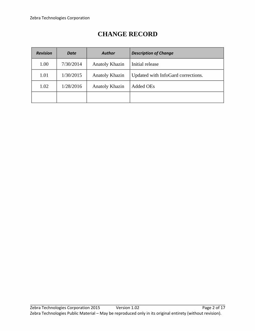
CHANGE RECORD
Revision Date Author Description of Change
1.00 7/30/2014 Anatoly Khazin Initial release
1.01 1/30/2015 Anatoly Khazin Updated with InfoGard corrections.
1.02 1/28/2016 Anatoly Khazin Added OEs
Zebra Technologies Corporation
Zebra Technologies Corporation 2015 Version 1.02 Page 3 of 17 Zebra Technologies Public Material – May be reproduced only in its original entirety (without revision).
TABLE OF CONTENTS 1 Introduction .................................................................................................................... 5
1.1 Hardware and Physical Cryptographic Boundary .........................................................................7
1.1.1 Hardware component WL1283CYFVR (Rev C) ................................................................7
1.1.2 Hardware component WL1273LYFVR .............................................................................8
1.1.3 Hardware component WL1273BYFVR .............................................................................9
1.1.4 Hardware component WL1271BYFVR (chip on board) ...................................................9
1.1.5 Hardware component WL1270BYFVR .......................................................................... 10
1.2 Logical Cryptographic Boundary ............................................................................................... 11 1.3 Modes of Operation .................................................................................................................. 12
2 Cryptographic Functionality ........................................................................................... 13
2.1 Critical Security Parameters ...................................................................................................... 13
3 Roles, Authentication and Services ................................................................................ 14
3.1 Assumption of Roles .................................................................................................................. 14 3.2 Services ...................................................................................................................................... 14
4 Self‐tests ........................................................................................................................ 15
5 Physical Security Policy .................................................................................................. 15
6 Operational Environment .............................................................................................. 16
7 Mitigation of Other Attacks Policy ................................................................................. 16
8 Security Rules and Guidance .......................................................................................... 16
9 References and Definitions ............................................................................................ 17
Zebra Technologies Corporation
Zebra Technologies Corporation 2015 Version 1.02 Page 4 of 17 Zebra Technologies Public Material – May be reproduced only in its original entirety (without revision).
ListofTables
Table 1 ‐ Cryptographic Module Configurations (Firmware1283_FIPS.bin) ................................................. 5
Table 2 – Cryptographic Module Configurations (Firmware1273_FIPS_CHIP.bin) ....................................... 5
Table 3 – Security Level of Security Requirements ....................................................................................... 6
Table 4 – Ports and Interfaces .................................................................................................................... 11
Table 5 – Approved and CAVP Validated Cryptographic Functions ............................................................ 13
Table 6 – Critical Security Parameters (CSPs) ............................................................................................. 13
Table 7 – Roles Description ......................................................................................................................... 14
Table 8 – Services ........................................................................................................................................ 14
Table 9 – CSP Access Rights within Services ............................................................................................... 15
Table 10 – Power Up Self‐tests ................................................................................................................... 15
Table 11 – References ................................................................................................................................. 17
Table 12 – Acronyms and Definitions ......................................................................................................... 17
ListofFigures
Figure 1 –Module Hardware Component WL1283CYFVR ............................................................................ 7
Figure 2 –Module Hardware Component WL1283CYFVR integrated to Connectivity chip .......................... 7
Figure 3 –Module Hardware Component WL1273LYFVR ............................................................................. 8
Figure 4 –Module Hardware Component WL1273LYFVR integrated to Connectivity chip .......................... 8
Figure 5 –Module Hardware Component WL1273CYFVR integrated to Connectivity chip .......................... 9
Figure 6 –Module Hardware Component WL1271BYFVR ............................................................................ 9
Figure 7 –Module Hardware Component WL1270BYFVR .......................................................................... 10
Figure 8 –Module Hardware Component WL1270BYFVR integrated to Connectivity chip........................ 10
Figure 9 – Module Block Diagram ............................................................................................................... 11
Zebra Technologies Corporation
Zebra Technologies Corporation 2015 Version 1.02 Page 5 of 17 Zebra Technologies Public Material – May be reproduced only in its original entirety (without revision).
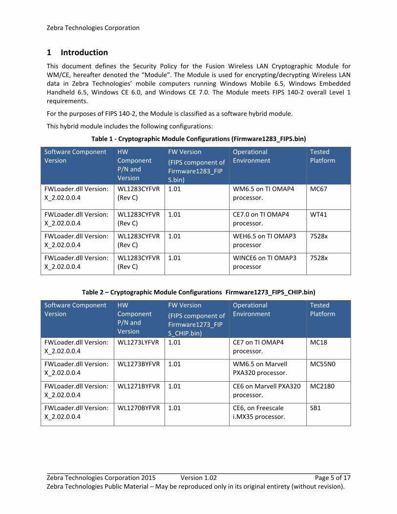
1 Introduction
This document defines the Security Policy for the Fusion Wireless LAN Cryptographic Module for WM/CE, hereafter denoted the “Module”. The Module is used for encrypting/decrypting Wireless LAN data in Zebra Technologies’ mobile computers running Windows Mobile 6.5, Windows Embedded Handheld 6.5, Windows CE 6.0, and Windows CE 7.0. The Module meets FIPS 140‐2 overall Level 1 requirements.
For the purposes of FIPS 140‐2, the Module is classified as a software hybrid module.
This hybrid module includes the following configurations:
Table 1 ‐ Cryptographic Module Configurations (Firmware1283_FIPS.bin)
Software Component Version
HW Component P/N and Version
FW Version
(FIPS component of Firmware1283_FIPS.bin)
Operational Environment
Tested Platform
FWLoader.dll Version: X_2.02.0.0.4
WL1283CYFVR (Rev C)
1.01 WM6.5 on TI OMAP4 processor.
MC67
FWLoader.dll Version: X_2.02.0.0.4
WL1283CYFVR (Rev C)
1.01 CE7.0 on TI OMAP4 processor.
WT41
FWLoader.dll Version: X_2.02.0.0.4
WL1283CYFVR (Rev C)
1.01 WEH6.5 on TI OMAP3 processor
7528x
FWLoader.dll Version: X_2.02.0.0.4
WL1283CYFVR (Rev C)
1.01 WINCE6 on TI OMAP3 processor
7528x
Table 2 – Cryptographic Module Configurations (Firmware1273_FIPS_CHIP.bin)
Software Component Version
HW Component P/N and Version
FW Version
(FIPS component of Firmware1273_FIPS_CHIP.bin)
Operational Environment
Tested Platform
FWLoader.dll Version: X_2.02.0.0.4
WL1273LYFVR 1.01 CE7 on TI OMAP4 processor.
MC18
FWLoader.dll Version: X_2.02.0.0.4
WL1273BYFVR 1.01 WM6.5 on Marvell PXA320 processor.
MC55N0
FWLoader.dll Version: X_2.02.0.0.4
WL1271BYFVR 1.01 CE6 on Marvell PXA320 processor.
MC2180
FWLoader.dll Version: X_2.02.0.0.4
WL1270BYFVR 1.01 CE6, on Freescale i.MX35 processor.
SB1
Zebra Technologies Corporation
Zebra Technologies Corporation 2015 Version 1.02 Page 6 of 17 Zebra Technologies Public Material – May be reproduced only in its original entirety (without revision).
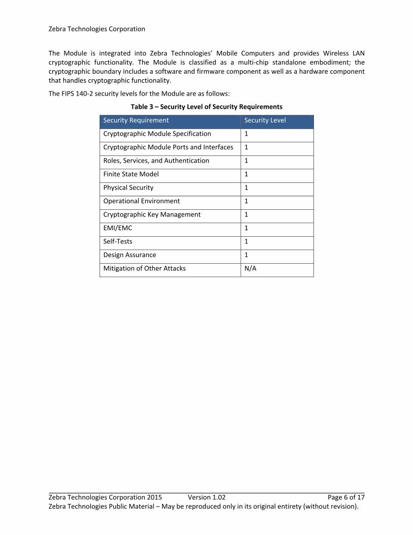
The Module is integrated into Zebra Technologies’ Mobile Computers and provides Wireless LAN cryptographic functionality. The Module is classified as a multi‐chip standalone embodiment; the cryptographic boundary includes a software and firmware component as well as a hardware component that handles cryptographic functionality.
The FIPS 140‐2 security levels for the Module are as follows:
Table 3 – Security Level of Security Requirements
Security Requirement Security Level
Cryptographic Module Specification 1
Cryptographic Module Ports and Interfaces 1
Roles, Services, and Authentication 1
Finite State Model 1
Physical Security 1
Operational Environment 1
Cryptographic Key Management 1
EMI/EMC 1
Self‐Tests 1
Design Assurance 1
Mitigation of Other Attacks N/A

Zebra Technologies Corporation
Zebra Technologies Corporation 2015 Version 1.02 Page 7 of 17 Zebra Technologies Public Material – May be reproduced only in its original entirety (without revision).
1.1 Hardware and Physical Cryptographic Boundary
Physical Cryptographic Boundary is the mobile computer that integrates the Module. The modules hardware components are depicted in sub‐sections below.
1.1.1 Hardware component WL1283CYFVR (Rev C)
The module’s hardware component is depicted in Figure 1. Figure 2 shows two (2) different connectivity chips that integrate Texas Instruments’ WL1283 chipset (the module’s hardware component), highlighted in red. Mobile Computers use one of the connectivity chips shown below in Figure 2.
Figure 1 –Module Hardware Component WL1283CYFVR (Rev C)
Figure 2 –Module Hardware Component WL1283CYFVR (Rev C) Integrated to Connectivity Chip
Zebra Technologies Corporation
Zebra Technologies Corporation 2015 Version 1.02 Page 8 of 17 Zebra Technologies Public Material – May be reproduced only in its original entirety (without revision).
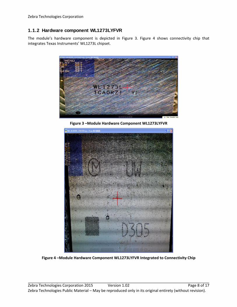
1.1.2 Hardware component WL1273LYFVR
The module’s hardware component is depicted in Figure 3. Figure 4 shows connectivity chip that integrates Texas Instruments’ WL1273L chipset.
Figure 3 –Module Hardware Component WL1273LYFVR
Figure 4 –Module Hardware Component WL1273LYFVR Integrated to Connectivity Chip
Zebra Technologies Corporation
Zebra Technologies Corporation 2015 Version 1.02 Page 9 of 17 Zebra Technologies Public Material – May be reproduced only in its original entirety (without revision).
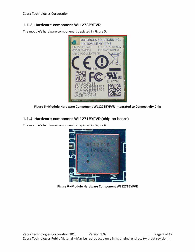
1.1.3 Hardware component WL1273BYFVR
The module’s hardware component is depicted in Figure 5.
Figure 5 –Module Hardware Component WL1273BYFVR Integrated to Connectivity Chip
1.1.4 Hardware component WL1271BYFVR (chip on board)
The module’s hardware component is depicted in Figure 6.
Figure 6 –Module Hardware Component WL1271BYFVR
Zebra Technologies Corporation
Zebra Technologies Corporation 2015 Version 1.02 Page 10 of 17 Zebra Technologies Public Material – May be reproduced only in its original entirety (without revision).
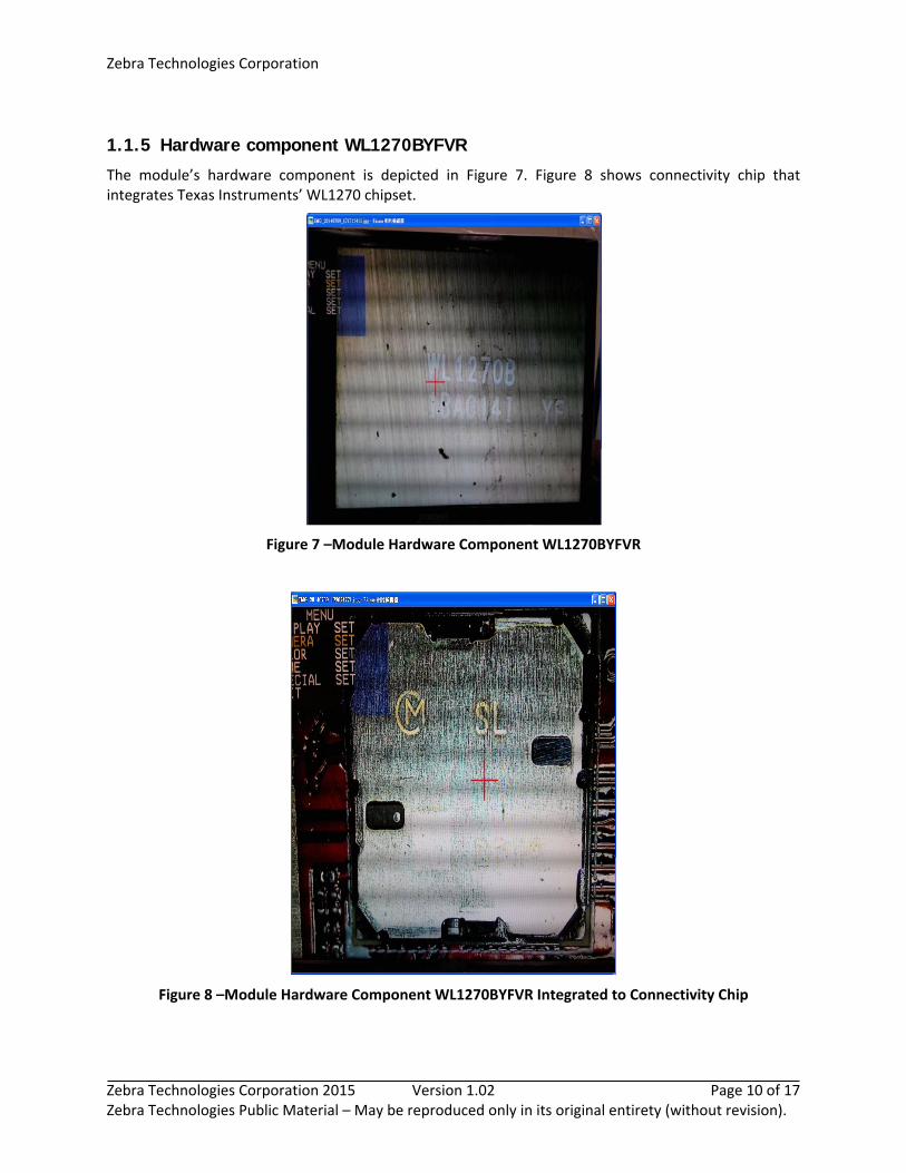
1.1.5 Hardware component WL1270BYFVR
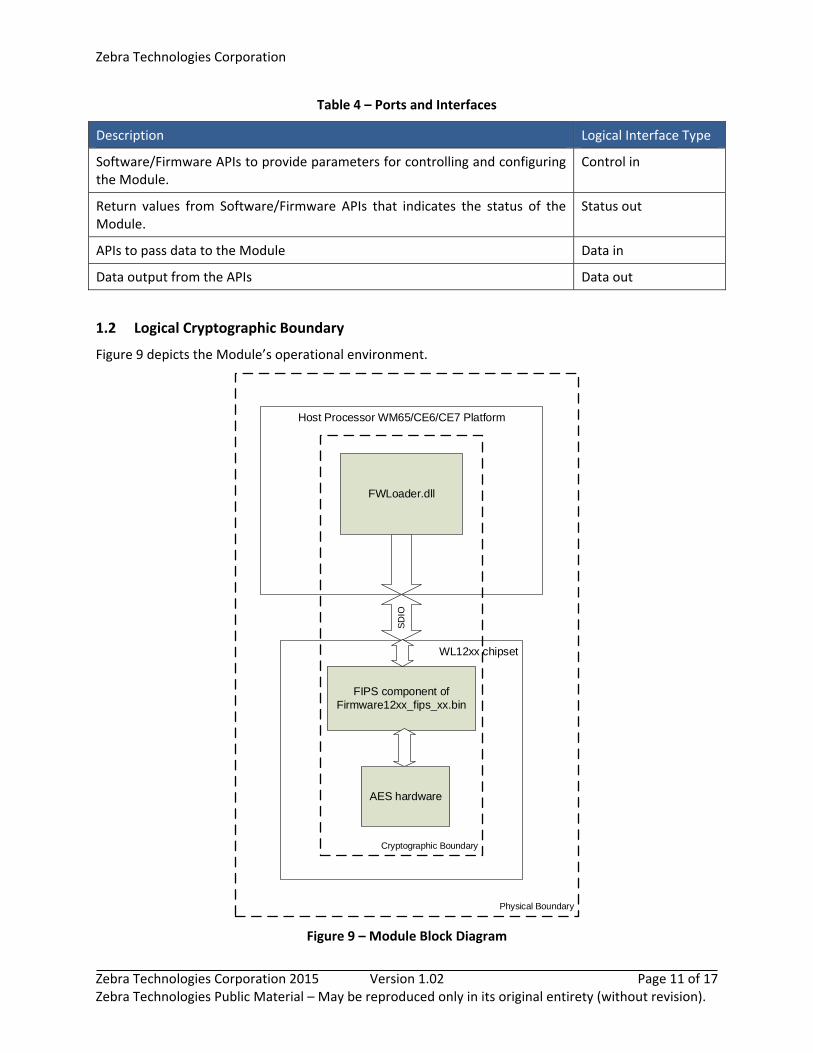
The module’s hardware component is depicted in Figure 7. Figure 8 shows connectivity chip that integrates Texas Instruments’ WL1270 chipset.
Figure 7 –Module Hardware Component WL1270BYFVR
Figure 8 –Module Hardware Component WL1270BYFVR Integrated to Connectivity Chip
Zebra Technologies Corporation
Zebra Technologies Corporation 2015 Version 1.02 Page 11 of 17 Zebra Technologies Public Material – May be reproduced only in its original entirety (without revision).
Table 4 – Ports and Interfaces
Description Logical Interface Type
Software/Firmware APIs to provide parameters for controlling and configuring the Module.
Control in
Return values from Software/Firmware APIs that indicates the status of the Module.
Status out
APIs to pass data to the Module Data in
Data output from the APIs Data out
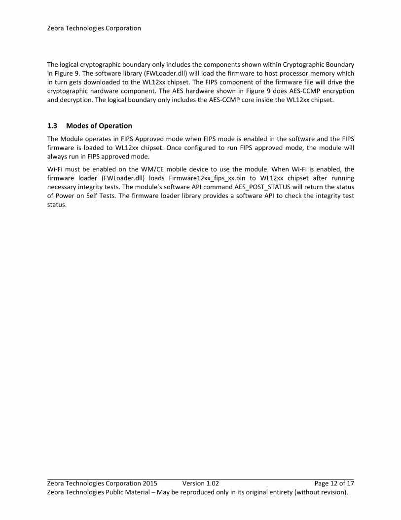
1.2 Logical Cryptographic Boundary
Figure 9 depicts the Module’s operational environment.
Host Processor WM65/CE6/CE7 Platform
FWLoader.dll
WL12xx chipset
FIPS component of Firmware12xx_fips_xx.bin
AES hardware
Cryptographic Boundary
SD
IO
Physical Boundary
Figure 9 – Module Block Diagram
Zebra Technologies Corporation
Zebra Technologies Corporation 2015 Version 1.02 Page 12 of 17 Zebra Technologies Public Material – May be reproduced only in its original entirety (without revision).
The logical cryptographic boundary only includes the components shown within Cryptographic Boundary in Figure 9. The software library (FWLoader.dll) will load the firmware to host processor memory which in turn gets downloaded to the WL12xx chipset. The FIPS component of the firmware file will drive the cryptographic hardware component. The AES hardware shown in Figure 9 does AES‐CCMP encryption and decryption. The logical boundary only includes the AES‐CCMP core inside the WL12xx chipset.
1.3 Modes of Operation
The Module operates in FIPS Approved mode when FIPS mode is enabled in the software and the FIPS firmware is loaded to WL12xx chipset. Once configured to run FIPS approved mode, the module will always run in FIPS approved mode.
Wi‐Fi must be enabled on the WM/CE mobile device to use the module. When Wi‐Fi is enabled, the firmware loader (FWLoader.dll) loads Firmware12xx_fips_xx.bin to WL12xx chipset after running necessary integrity tests. The module’s software API command AES_POST_STATUS will return the status of Power on Self Tests. The firmware loader library provides a software API to check the integrity test status.
Zebra Technologies Corporation
Zebra Technologies Corporation 2015 Version 1.02 Page 13 of 17 Zebra Technologies Public Material – May be reproduced only in its original entirety (without revision).
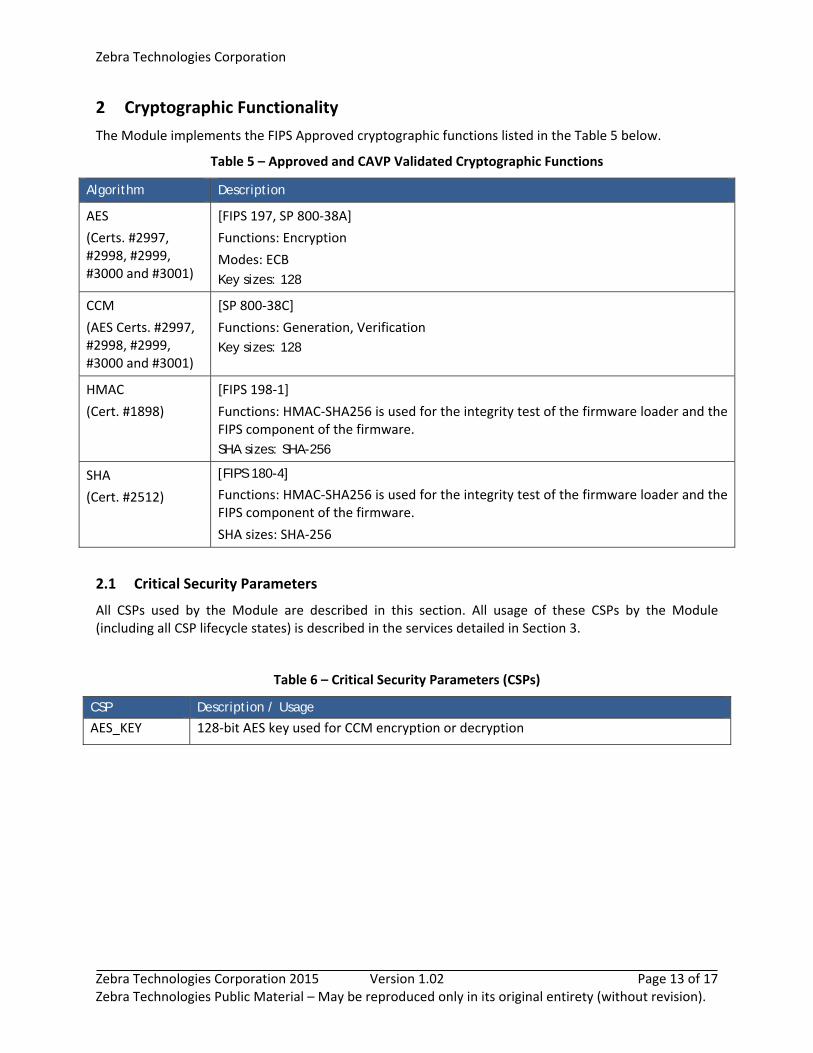
2 Cryptographic Functionality
The Module implements the FIPS Approved cryptographic functions listed in the Table 5 below.
Table 5 – Approved and CAVP Validated Cryptographic Functions
Algorithm Description
AES
(Certs. #2997, #2998, #2999, #3000 and #3001)
[FIPS 197, SP 800‐38A]
Functions: Encryption
Modes: ECB
Key sizes: 128
CCM
(AES Certs. #2997, #2998, #2999, #3000 and #3001)
[SP 800‐38C]
Functions: Generation, Verification
Key sizes: 128
HMAC
(Cert. #1898)
[FIPS 198‐1]
Functions: HMAC‐SHA256 is used for the integrity test of the firmware loader and the FIPS component of the firmware.
SHA sizes: SHA-256
SHA
(Cert. #2512)
[FIPS 180-4]
Functions: HMAC‐SHA256 is used for the integrity test of the firmware loader and the FIPS component of the firmware.
SHA sizes: SHA‐256
2.1 Critical Security Parameters
All CSPs used by the Module are described in this section. All usage of these CSPs by the Module (including all CSP lifecycle states) is described in the services detailed in Section 3.
Table 6 – Critical Security Parameters (CSPs)
CSP Description / Usage
AES_KEY 128‐bit AES key used for CCM encryption or decryption
Zebra Technologies Corporation
Zebra Technologies Corporation 2015 Version 1.02 Page 14 of 17 Zebra Technologies Public Material – May be reproduced only in its original entirety (without revision).
3 Roles, Authentication and Services
3.1 Assumption of Roles
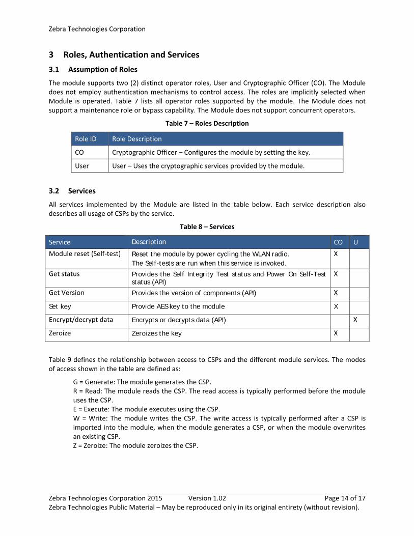
The module supports two (2) distinct operator roles, User and Cryptographic Officer (CO). The Module does not employ authentication mechanisms to control access. The roles are implicitly selected when Module is operated. Table 7 lists all operator roles supported by the module. The Module does not support a maintenance role or bypass capability. The Module does not support concurrent operators.
Table 7 – Roles Description
Role ID Role Description
CO Cryptographic Officer – Configures the module by setting the key.
User User – Uses the cryptographic services provided by the module.
3.2 Services
All services implemented by the Module are listed in the table below. Each service description also describes all usage of CSPs by the service.
Table 8 – Services
Service Description CO U
Module reset (Self‐test) Reset the module by power cycling the WLAN radio. The Self-tests are run when this service is invoked.
X
Get status Provides the Self Integrity Test status and Power On Self-Test status (API)
X
Get Version Provides the version of components (API) X
Set key Provide AES key to the module X
Encrypt/decrypt data Encrypts or decrypts data (API) X
Zeroize Zeroizes the key X
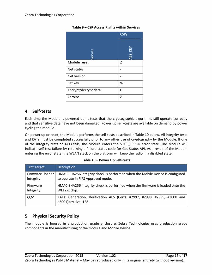
Table 9 defines the relationship between access to CSPs and the different module services. The modes of access shown in the table are defined as:
G = Generate: The module generates the CSP. R = Read: The module reads the CSP. The read access is typically performed before the module uses the CSP. E = Execute: The module executes using the CSP. W = Write: The module writes the CSP. The write access is typically performed after a CSP is imported into the module, when the module generates a CSP, or when the module overwrites an existing CSP. Z = Zeroize: The module zeroizes the CSP.
Zebra Technologies Corporation
Zebra Technologies Corporation 2015 Version 1.02 Page 15 of 17 Zebra Technologies Public Material – May be reproduced only in its original entirety (without revision).
Table 9 – CSP Access Rights within Services
Service
CSPs
AES_K
EY
Module reset Z
Get status ‐
Get version ‐
Set key W
Encrypt/decrypt data E
Zeroize Z
4 Self‐tests
Each time the Module is powered up, it tests that the cryptographic algorithms still operate correctly and that sensitive data have not been damaged. Power up self–tests are available on demand by power cycling the module.
On power up or reset, the Module performs the self‐tests described in Table 10 below. All integrity tests and KATs must be completed successfully prior to any other use of cryptography by the Module. If one of the integrity tests or KATs fails, the Module enters the SOFT_ERROR error state. The Module will indicate self‐test failure by returning a failure status code for Get Status API. As a result of the Module entering the error state, the WLAN stack on the platform will keep the radio in a disabled state.
Table 10 – Power Up Self‐tests
Test Target Description
Firmware loader integrity
HMAC‐SHA256 integrity check is performed when the Mobile Device is configured to operate in FIPS Approved mode.
Firmware Integrity
HMAC‐SHA256 integrity check is performed when the firmware is loaded onto the WL12xx chip.
CCM KATs: Generation, Verification AES (Certs. #2997, #2998, #2999, #3000 and #3001)Key size: 128
5 Physical Security Policy
The module is housed in a production grade enclosure. Zebra Technologies uses production grade components in the manufacturing of the module and Mobile Device.
Zebra Technologies Corporation
Zebra Technologies Corporation 2015 Version 1.02 Page 16 of 17 Zebra Technologies Public Material – May be reproduced only in its original entirety (without revision).
6 Operational Environment
The Module is designated as a modifiable operational environment under the FIPS 140‐2 definitions. The Module includes a firmware loader software library that reads the firmware and loads it into the hardware. The Module is integrated into Mobile Devices that uses the OMAP4 based WM65/CE6/CE7 platform. The software library (FWLoader.dll) runs in the context of WM65/CE6/CE7 Operating Systems. Only a single user can operate the Module at a time.
7 Mitigation of Other Attacks Policy
The module does not implement mitigation for any other attacks.
8 Security Rules and Guidance
The Module design corresponds to the Module security rules. This section documents the security rules enforced by the cryptographic module to implement the security requirements of this FIPS 140‐2 Level 1 module.
The module provides two (2) distinct operator roles: User and Cryptographic Officer.
The operator can command the module to perform the power up self‐tests by cycling power or resetting the module.
Power up self‐tests do not require any operator action.
Data output is inhibited during self‐tests, zeroization, and error states.
Status information does not contain CSPs or sensitive data that if misused could lead to a compromise of the module.
There are no restrictions on which keys or CSPs are zeroized by the zeroization service.
The module does not support a maintenance interface or role.
The module does not have any external input/output devices used for entry/output of data.
Zebra Technologies Corporation
Zebra Technologies Corporation 2015 Version 1.02 Page 17 of 17 Zebra Technologies Public Material – May be reproduced only in its original entirety (without revision).
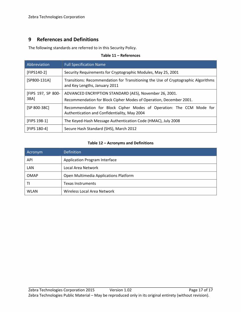
9 References and Definitions
The following standards are referred to in this Security Policy.
Table 11 – References
Abbreviation Full Specification Name
[FIPS140‐2] Security Requirements for Cryptographic Modules, May 25, 2001
[SP800‐131A] Transitions: Recommendation for Transitioning the Use of Cryptographic Algorithms and Key Lengths, January 2011
[FIPS 197, SP 800‐38A]
ADVANCED ENCRYPTION STANDARD (AES), November 26, 2001.
Recommendation for Block Cipher Modes of Operation, December 2001.
[SP 800‐38C] Recommendation for Block Cipher Modes of Operation: The CCM Mode for Authentication and Confidentiality, May 2004
[FIPS 198‐1] The Keyed‐Hash Message Authentication Code (HMAC), July 2008
[FIPS 180‐4] Secure Hash Standard (SHS), March 2012
Table 12 – Acronyms and Definitions
Acronym Definition
API Application Program Interface
LAN Local Area Network
OMAP Open Multimedia Applications Platform
TI Texas Instruments
WLAN Wireless Local Area Network