zdauto automation zd-mio-raspberrypi3-kit i/o expansion
TRANSCRIPT

ZDAUTO Automation
ZD-MIO-RASPBERRYPI3-KIT
I/O Expansion Board
Extension Module Assembly
Product Manuals(V1.1)
www.zdauto.com
ZDAUTO Automation Technology Co.,LTD.
1993-2020

1
Catalog
1. Introduction.................................................................................................................................................................2
2. Product feature........................................................................................................................................................... 2
3. Extension board standard combination configuration...............................................................................................3
4. Pin description............................................................................................................................................................ 4
5. Wiring diagram of expansion board........................................................................................................................... 5
6. Introduction of M5S module functions...................................................................................................................... 6
7. Practical application of expansion board..................................................................................................................10
8. Raspberry pi version configuration parameters introduced.................................................................................... 11
9. Raspberry pi pin definition....................................................................................................................................... 12
10. Raspberry-Pi-3 wiring diagram............................................................................................................................... 13
11. Demo running sample software............................................................................................................................. 14
12. Program code display..............................................................................................................................................17

2
1. Introduction
Raspberry Pi is a credit card sized development board, it can run the LINUX operation
system, and replay the desktop computer daily work ,such as word processing, spreadsheet, or
even games and media center. You can use Raspberry Pi to connect to television, monitors,
keyboards, mouse, and other devices. It can be developed as a device what we want.
ZDAUTO-MIO-Raspberry Pi is a I/O development board compatible with Raspberry Pi , it can
lead the Raspberry Pi’s I/O interface to the development board , and add the Smart Relay
module, switching value modules, analog quantity modules, pulsed quantity modules can be
choose to accessed the peripheral devices.
ZD-MIO-Raspberry Pi 3-KIT extension board is standard equipped with 4 M5S modules,
and the other 4 blank bases allow users to purchase M5S modules and insert them to realize
different functions.
2. Product feature
-The expansion board has eight M5S module bases, and customers can select modules
according to their functional requirements to realize the designed functions.
-External circuit access and switching voltages can be higher than the rated voltage on the
Raspberry PI;
-Select isolation module, realize circuit isolation, improve module security;

3
3. Extension board standard combination configuration
-ZDAUTO-MIO-Raspberry Pi Extension board *1(It contains 8 M5S bases and can access 8 M5S modules)
-M5S-BID0324B1 *1
-M5S-BOT03750D1b *2
-M5S-AOA03020D3Ab *1
-Original Jumper Cap *9
-Original Tweezers (for pulling out M5S parts) *1
-Original Jumper *8
(If you need blank expansion board, please contact customer service)
Type selection Tips:
1. The standard M5S-BID0324B1 module does not have the pull resistance function. If
you want to have a strong driving ability, it is recommended to choose the module
with the pull resistance internally, otherwise you must design the driver program in
the chip.
2. When the source module is not switched on, it is low; when switched on, it is
high.Therefore, it is recommended to select the source type module (such as BID.xx.
yyy.B1) for external drive with high power.
Conversely, the leakage module is high when not switched on, and low when
switched on.
Therefore, it is recommended to choose leaky module (such as BID.xx. yyy.A1) for
external drive with low power.
4
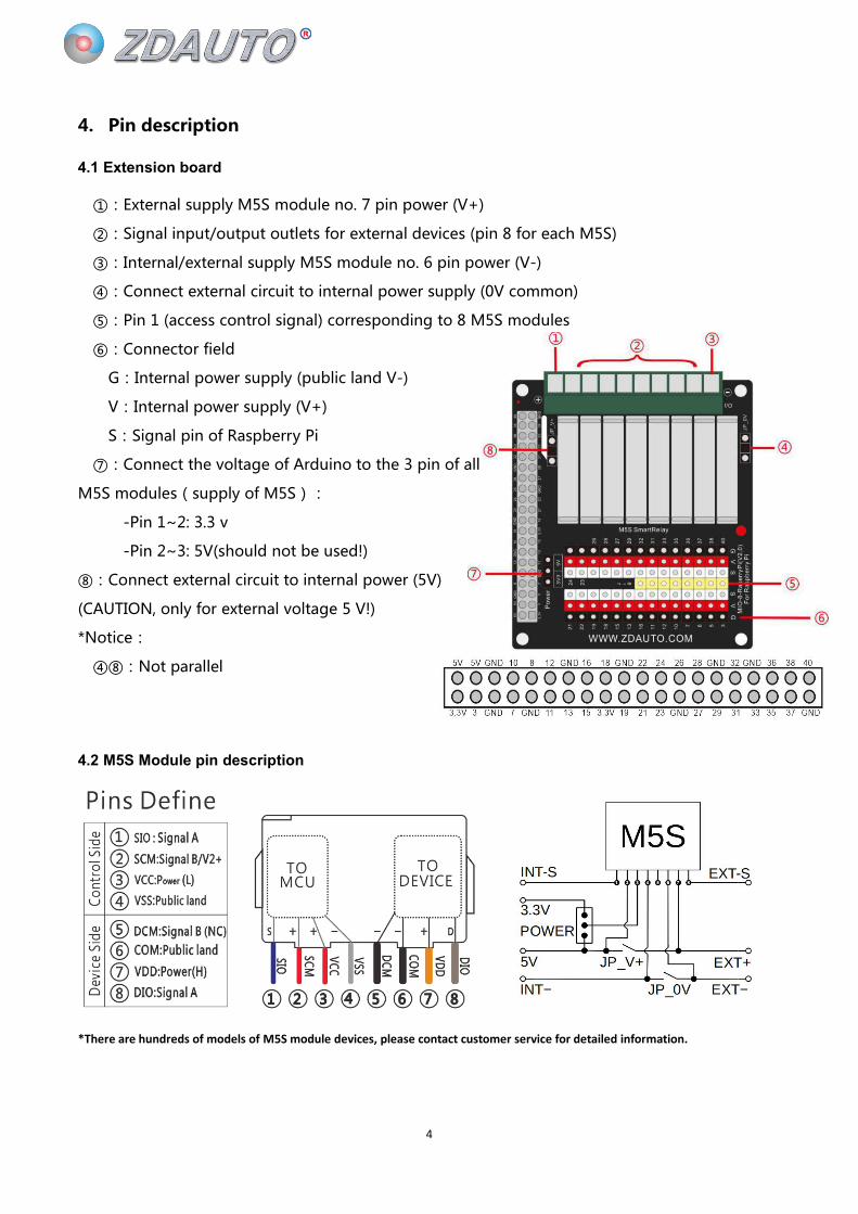
4. Pin description
4.1 Extension board
①:External supply M5S module no. 7 pin power (V+)
②:Signal input/output outlets for external devices (pin 8 for each M5S)
③:Internal/external supply M5S module no. 6 pin power (V-)
④:Connect external circuit to internal power supply (0V common)
⑤:Pin 1 (access control signal) corresponding to 8 M5S modules
⑥:Connector field
G:Internal power supply (public land V-)
V:Internal power supply (V+)
S:Signal pin of Raspberry Pi
⑦:Connect the voltage of Arduino to the 3 pin of all
M5S modules(supply of M5S):
-Pin 1~2: 3.3 v
-Pin 2~3: 5V(should not be used!)
⑧:Connect external circuit to internal power (5V)
(CAUTION, only for external voltage 5 V!)
*Notice:
④⑧:Not parallel
4.2 M5S Module pin description
*There are hundreds of models of M5S module devices, please contact customer service for detailed information.
5
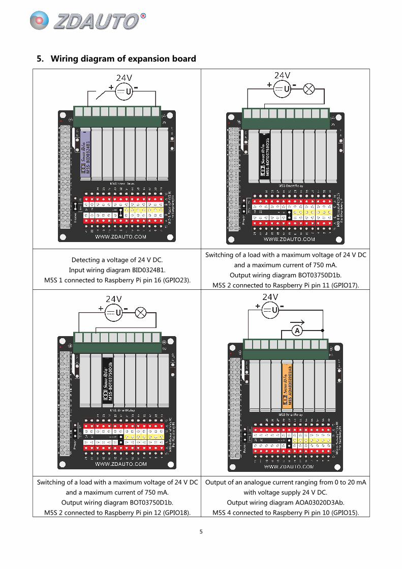
5. Wiring diagram of expansion board
Detecting a voltage of 24 V DC.
Input wiring diagram BID0324B1.
M5S 1 connected to Raspberry Pi pin 16 (GPIO23).
Switching of a load with a maximum voltage of 24 V DC
and a maximum current of 750 mA.
Output wiring diagram BOT03750D1b.
M5S 2 connected to Raspberry Pi pin 11 (GPIO17).
Switching of a load with a maximum voltage of 24 V DC
and a maximum current of 750 mA.
Output wiring diagram BOT03750D1b.
M5S 2 connected to Raspberry Pi pin 12 (GPIO18).
Output of an analogue current ranging from 0 to 20 mA
with voltage supply 24 V DC.
Output wiring diagram AOA03020D3Ab.
M5S 4 connected to Raspberry Pi pin 10 (GPIO15).

7
6. Introduction of M5S module functions
6.1 M5S-BID0324B1
Optical Isolated,DC Digital Sourcing Input(Input:DC,PNP,6-8 pin; Output: without pull-up resistor,NPN,OC Output, 1-4 pin)
Model
Control Side(Output)Frequency Isolation
Device Side(Input)Circuit
indexVoltage(1) Current(1) Power(3) Polarity Voltage(8) Current(8) Power(7) Polarity
M5S-BID0324B1H:3.3V
L:0V
Max
8mAx
N
OC0~5KH ● 24VDC
L:7mA
H:1mAx P B1

8
6.2 M5S-BOT03750D1b
Optical Isolated,Transistor Digital Sourcing Output(Input:1,3 pin N signal,7-8 pin Transistor-OC-P, Transistor header electrode open circuit output
Model
Control Side(Input)Frequency Isolation
Device Side(Output)Circuit
indexVoltage(1) Current(1) Power Polarity Voltage(8) Current(8) Power Polarity
M5S-BOT03750D1bON:0V
OFF:5V
Max
7mA3.3V N 0~20KHz ● DC 24V
Max
750mAx
P
TOCD1

9
6.3 M5S-AOA03020D3Ab
Optical Isolated,PWM type current analog Output(Input,1,3 TTL level PWM signal,Output: voltage signal,6-7-8pin)
Model
Control Side(Input)Frequency Isolation
Device Side(Input)Circuit
indexVoltage(1) Current(1) Power Voltage(8) Voltage(8) Current(8) Power
Frequency
response
M5S-AOA03020D3Ab PWM <5mA 3.3V 3% linear ● 0~20mA 24V 1KHz D3A
10
7. Practical application of expansion board
The I/O expansion board is equipped with 1 channel BI switch input, 2 channel BO switch
input and 1 channel AO analog output module. In addition, it is also optional to add 4 channels
M5S module.
GPIO point can be controlled based on raspberry PI platform and connected with the
corresponding signal pin of M5S switch input and output module, so as to connect with
external devices , such as binary input devices (switches, knobs, limit switches, water level
switches, buttons) and binary output devices ( relay, contacts, solenoid valve, heating wire,
buzzer, motor). Similarly, it also can control the analog input devices, such as (Access
potentiometer, temperature sensor, pressure sensor),and the analog output devices(Control
motor speed, adjust furnace temperature, control tension, etc).

11
8. Raspberry pi version configuration parameters introduced
Model A type A+type B type B+type2 generation
s B type3 generations B type
SOC BroadcomBCM2835(CPU,GPU,DSP and SDRAM,USB)Broadcom B
CM2836Broadcom BCM2837
CPU ARM1176JZF-S Core(ARM11 Series)700MHz
ARM Cortex
-A7 (ARMv7
Series) 900
MHz (Four c
ore)
ARM Cortex-A53 1.2GHz 64-
bit quad-core ARMv8 CPU
GPU Broadcom Video Crore IV,OpenGL ES 2.0,1080p 30 h.264/MPEG-4 AVC Hd decoder
Memory
256 MB(Share with the GP
U,Can be understood as int
egrated graphics memory an
d memory sharing)
512MB 1GB (LPDDR2)
USB 2.0
Port num
ber
1(support USB hub extensio
n)2 4
Video in
put
15-needles MIPI camera (CSI) interface,Can be used by raspberry pie camera or raspberry pie camera (no infr
ared version)
The outp
ut image
RCA Video interface output(Only generation B has this port),support PAL and NTSC standard,support HDM
I (1.3 and 1.4),
Resolution of 640 x 350 to 1920 x 1200 support PAL 和 NTSC standard。
Audio ou
tput3.5mm jack socket,HDMI electronic output or I²S
The onbo
ard stora
ge
SD/MMC/SD
IO card slot
MicroSD car
d slot
SD / MMC
/ SDIO card
slot
MicroSD card slot
Network
portNot have 10/100 Ethernet interface
10/100 Ethernet interfac
e
802.11n Wireless LAN
Bluetooth 4.1
Bluetooth Low Energy
(BLE)

12
9. Raspberry pi pin definition
wringPi
编码
BCM
编码
功能名 物理引脚
BOARD 编码
功能名 BCM
编码
wringPi
编码
3.3V 1 2 5V
8 2 SDA.1 3 4 5V
9 3 SCL.1 5 6 GND
7 4 GPIO.7 7 8 TXD 14 15
GND 9 10 RXD 15 16
0 17 GPIO.0 11 12 GPIO.1 18 1
2 27 GPIO.2 13 14 GND
3 22 GPIO.3 15 16 GPIO.4 23 4
3.3V 17 18 GPIO.5 24 5
12 10 MOSI 19 20 GND
13 9 MISO 21 22 GPIO.6 25 6
14 11 SCLK 23 24 CE0 8 10
GND 25 26 CE1 7 11
30 0 SDA.0 27 28 SCL.0 1 31
21 5 GPIO.21 29 30 GND
22 6 GPIO.22 31 32 GPIO.26 12 26
23 13 GPIO.23 33 34 GND
24 19 GPIO.24 35 36 GPIO.27 16 27
25 26 GPIO.25 37 38 GPIO.28 20 28
GND 39 40 GPIO.29 21 29

13
10. Raspberry-Pi-3 wiring diagram
Expansion board wiring diagram, clear version please see the attachment
14
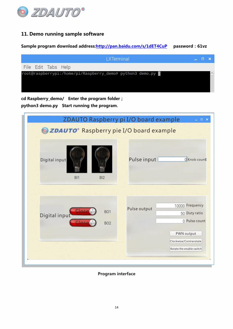
11. Demo running sample software
Sample program download address:http://pan.baidu.com/s/1dET4CuP password:61vz
cd Raspberry_demo/ Enter the program folder;
python3 demo.py Start running the program.
Program interface

15
Digital output:
Pulse input:
Pulse input:
Pulse output:
Digital input:

16

17
12. Program code display
12.1initialization:
#导入所运行程序必须的库文件
import RPi.GPIO as gpioimport time,osfrom PyQt5 import QtCore, QtGui, QtWidgetsfrom PyQt5.QtCore import Qt,QThread,pyqtSignal
gpio.setwarnings(False)
#------------------------global_trigger------------------------#
global pwm_num,pwm_countpwm_num=0pwm_count=0
#--------------------------gpio_setup---------------------------##根据需要分别将各个连接着 M5S 模块的 gpio 口设定为所需要的模式
gpio.setmode(gpio.BOARD)gpio.setup(32,gpio.IN) #BIgpio.setup(31,gpio.IN)
gpio.setup(33,gpio.IN) #PI
gpio.setup(37,gpio.OUT) #BO_lightbulbgpio.output(37,1)gpio.setup(36,gpio.OUT)gpio.output(36,1)
gpio.setup(38,gpio.OUT) #BO_DIRgpio.setup(40,gpio.OUT) #BO_ENA

18
12.2 PI, BI function thread:
class BI_thread(QThread):def run(self):
while True:b = gpio.input(32)c = gpio.input(31)
#根据 IO 口的对应状态更新 UIif b == 1:
ui.lightbulb1.setPixmap(QtGui.QPixmap("img/light_off.jpg"))time.sleep(0.001)
if b == 0:ui.lightbulb1.setPixmap(QtGui.QPixmap("img/light_on.jpg"))time.sleep(0.001)
if c == 1:ui.lightbulb2.setPixmap(QtGui.QPixmap("img/light_off.jpg"))time.sleep(0.001)
if c == 0:ui.lightbulb2.setPixmap(QtGui.QPixmap("img/light_on.jpg"))time.sleep(0.001)
class PI_thread(QThread):def run(self):
count=0while True:
a = gpio.input(33)if a == 0:
count += 1 #IO 口状态跳变一次计数值+1ui.lineEdit.setText(str(count))

19
12.3 BO control bulb function:
def light_control(self):
icon = QtGui.QIcon()
gpio.output(36,not gpio.input(36))if gpio.input(36) == 1:
icon.addPixmap(QtGui.QPixmap("img/off.jpg"), QtGui.QIcon.Normal, QtGui.QIcon.Off)self.t1.setIcon(icon)
else:icon.addPixmap(QtGui.QPixmap("img/on.jpg"), QtGui.QIcon.Normal, QtGui.QIcon.Off)self.t1.setIcon(icon)
def light2_control(self):
icon = QtGui.QIcon()
gpio.output(37,not gpio.input(37))if gpio.input(37) == 1:
icon.addPixmap(QtGui.QPixmap("img/off.jpg"), QtGui.QIcon.Normal, QtGui.QIcon.Off)self.t2.setIcon(icon)
else:icon.addPixmap(QtGui.QPixmap("img/on.jpg"), QtGui.QIcon.Normal, QtGui.QIcon.Off)self.t2.setIcon(icon)
20
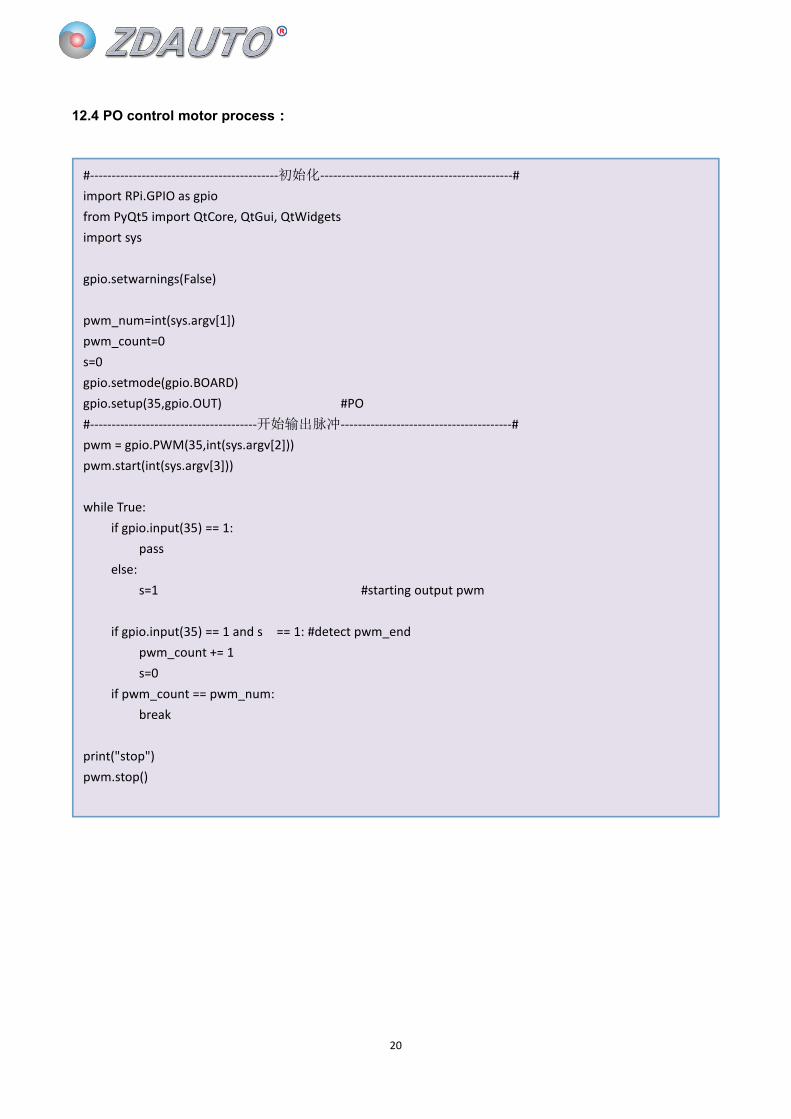
12.4 PO control motor process:
#--------------------------------------------初始化---------------------------------------------#import RPi.GPIO as gpiofrom PyQt5 import QtCore, QtGui, QtWidgetsimport sys
gpio.setwarnings(False)
pwm_num=int(sys.argv[1])pwm_count=0s=0gpio.setmode(gpio.BOARD)gpio.setup(35,gpio.OUT) #PO#---------------------------------------开始输出脉冲----------------------------------------#pwm = gpio.PWM(35,int(sys.argv[2]))pwm.start(int(sys.argv[3]))
while True:if gpio.input(35) == 1:
passelse:
s=1 #starting output pwm
if gpio.input(35) == 1 and s == 1: #detect pwm_endpwm_count += 1s=0
if pwm_count == pwm_num:break
print("stop")pwm.stop()