zambia bureau of standard - erb.org.zm repair of containers ... sans 347 categorization and...
TRANSCRIPT

Public Comment Draft Draft Zambian Standard
Portable Metal Containers for Compressed, Dissolved and Liquefied Gases: Basic Design Criteria, Use and Maintenance - Code of Practice
This draft standard is for public comment only. It must not be used or referred to as a Zambian Standard.
ZAMBIA BUREAU OF STANDARD
DZS 749 : 2011


DZS 749: 2011
i
DATE OF PUBLICATION This Zambian Standard has been published under the authority of the Standards Council of the Zambia Bureau of Standards on ………………. ZAMBIA BUREAU OF STANDARDS The Zambia Bureau of Standards is the Statutory National Standards Body for Zambia established under an Act of Parliament, the Standards Act, Cap 416 of 1994 of the Laws of Zambia for the preparation and promulgation of Zambian Standards. REVISION OF ZAMBIAN STANDARDS Zambian Standards are revised, when necessary, by the issue of either amendments or of revised editions. It is important that users of Zambian Standards should ascertain that they are in possession of the latest amendments or editions. CONTRACT REQUIREMENTS A Zambian standard does not purport to include all the necessary provisions of a contract. Users of Zambian standards are responsible for their correct application. TECHNICAL COMMITTEE RESPONSIBLE This Zambian Standard was prepared by the Technical Committee – Mechanical Engineering & Metallurgy Division (MMD TC 7/..) upon which the following organisations were represented: Alfred H. Knight (Z) Limited Caltex Oil Zambia Limited Energy Regulation Board (Secretary) Indeni Petroleum Refinery Company Limited Zambia Weights and Measures Agency Lusaka Fire Brigade, Lusaka City Council Ministry of Commerce, Trade and Industry Zambia Bureau of Standards ZAMBIA BUREAU OF STANDARDS, P.O. BOX 50259, ZA 15101 RIDGEWAY, ZAMBIA

DZS 749: 2011
ii
Table of Contents FOREWORD iv 1. SCOPE 7 2. NORMATIVE REFERENCES ............................................................................................ 7 3. DEFINITIONS .................................................................................................................... 8 4.0 CONTAINERS .................................................................................................................. 11 4.1 General ......................................................................................................................... 11 4.2 Symbols Used ............................................................................................................... 11 4.3 Basic Design Criteria .................................................................................................... 12 4.4 Special Purpose Containers ........................................................................................... 15 4.5 Re-Use/Change of Containers ....................................................................................... 15 4.6 Repair of Containers ..................................................................................................... 15 4.7 Valves .......................................................................................................................... 16 4.8 Safety Devices .............................................................................................................. 17 4.9 Inspection Openings ..................................................................................................... 18 5 MARKING, LABELLING AND CERTIFICATES ............................................................ 18 5.1 Permanent Marking on Containers ................................................................................ 18 5.2 COLOUR CODING OF CONTAINERS ...................................................................... 20 5.4 LABELLING ............................................................................................................... 21 5.5 CERTIFICATES .......................................................................................................... 21 6. INSPECTION AND TESTING OF CONTAINERS........................................................... 22 6.1 Inspection and Testing Stations ..................................................................................... 22 6.2 Documentation and Equipment ..................................................................................... 22 6.3 Inspection and Test Procedures ..................................................................................... 23 6.4 Condemned Containers ................................................................................................. 25 6.5 Stamping and Records .................................................................................................. 25 6.6 Repainting .................................................................................................................... 25 7 FILLING OF CONTAINERS ............................................................................................ 25 7.1 General ......................................................................................................................... 25 7.2 Persons Competent To Fill Containers .......................................................................... 25 7.3 Inspection before Filling ............................................................................................... 26 7.4 Filling With Permanent Gases ....................................................................................... 26 7.5 Filling With Liquefiable Gases ..................................................................................... 26 7.6 Precautions for Specific Gases ...................................................................................... 27 7.7 Filling Of Containers Already In Use ............................................................................ 29 7.9 Filling Of Containers for Use outside Zambia ............................................................... 29 8 HANDLING, STORAGE, TRANSPORTATION AND USE ............................................. 29 8.1 Handling....................................................................................................................... 29 8.2 Stacking ....................................................................................................................... 29 8.3 Storage ......................................................................................................................... 30 8.4 Transportation .............................................................................................................. 30 8.5 Use ............................................................................................................................... 31 9 GENERAL SAFETY PRECAUTIONS ............................................................................. 32 9.1 Containers Exposed To Fire .......................................................................................... 32 9.2 Inspection 33 9.3 Valves .......................................................................................................................... 32 9.4 Position and Support Of Containers In Use ................................................................... 32

DZS 749: 2011
iii
10 APPROVAL OF FOREIGN STANDARDS, RATING OF CONTAINERS MADE TO FOREIGN STANDARDS AND RE-RATING OF EXISTING CONTAINERS 33
10.1 Approval of Foreign Standards and Containers Made To Foreign Standards .................. 33 10.2 Procedure for Rating of Containers Produced According To Approved Foreign Standards
(Determination Of The Z Factor) .................................................................................. 33 10.3 Re-Rating Of Existing Containers ................................................................................. 33 TABLE 1 – REFERENCE TEMPERATURES.......................................................................... 35 TABLE 2A – PROPERTIES AND PRESSURE GROUPS OF PERMANENT GASES* ........... 36 TABLE 2B – PERMANENT GASES: CHARGING PRESSURES AND CORRESPONDING
DEVELOPED PRESSURES ............................................................................ 37 TABLE 2C – PERMANENT GASES: DEVELOPED PRESSURES AND CORRESPONDING
CHARGING PRESSURES ............................................................................... 38 TABLE 3 – HIGH PRESSURE LIQUEFIABLE GASES .......................................................... 39 TABLE 4 – LOW PRESSURE LIQUEFIABLE GASES ........................................................... 41 TABLE 5 – FILLING RATIOS FOR HYDROCARBON GAS MIXTURES ............................. 43 TABLE 6 – FREQUENCY OF INSPECTIONS AND TESTS ................................................... 44 TABLE 8 – COLOUR CODING OF GAS CYLINDERS .......................................................... 47 TABLE 9 – IMPURITIES IN COMPRESSED AIR FOR BREATHING ................................... 48 APPENDIX A. RE-RATING: EXAMPLE OF THE CALCULATION OF THE EQUIVALENT
PRESSURE AND THE Z FACTOR FOR A WELDED CONTAINER ALREADY IN USE ......................................................................................... 48
APPENDIX B. EXTERNAL AND INTERNAL EXAMINATION: COMMON DEFECTS AND CRITERIA FOR REJECTION ......................................................................... 50
TABLE B-1 – DEFECTS OTHER THAN CORROSION DEFECTS ........................................ 50 TABLE B-2 – CORROSION DEFECTS ................................................................................... 51 APPENDIX C: RECOMMENDED FIELD TEST METHODS FOR THE DETERMINATION
OF IMPURTIES IN COMPRESSED AIR FOR BREATHING ......................... 52
DZS 749: 2011
iv
FOREWORD The Zambia Bureau of Standards (ZABS) is the Statutory Organization established by an Act of Parliament. ZABS is responsible for the preparation of national standards through its various Technical Committees composed of representation from government departments, the industry, academia, regulators, consumer associations and non- governmental organisations. This National standard has been prepared in accordance with the procedures of the ZABS. All users should ensure that they have the latest edition of this publication as standards are revised from time to time. No liability shall attach to ZABS or its Director, employees, servants or agents including individual experts and members of its Technical Committees for any personal injury, property damage or other damages of any nature whatsoever, whether direct or indirect, or for costs (Including legal fees) and expenses arising out of the publication, use of, or reliance upon this ZABS publication or any other ZABS publication.

DZS 749: 2011
v
COMPLIANCE WITH A ZAMBIAN STANDARD DOES NOT OF ITSELF CONFER IMMUNITY FROM LEGAL OBLIGATIONS

DZS 749: 2011
6

DZS 749: 2011
7
1. SCOPE 1.1 This code of practice covers the basic design criteria, use and maintenance for portable metal
containers for compressed, dissolved and liquefied gases of water capacity 0.5 litres to 3,000 litres. The code also covers the repair of portable metal containers, as well as the use, filling, routine inspection, testing, handling and marking of such containers.
1.2 In addition to industrial, medical and domestic type gas cylinders, the code also covers cylinders for
self-contained underwater breathing apparatus (SCUBA), self-contained surface breathing apparatus (SCBA), and certain special purpose containers, but does not cover special cylinder for use in aircraft, disposable containers, fire fighting and air brakes systems.. NOTE
a) An example of the method for the re-rating of a welded container is given in Appendix A. b) Common defects that may be found during internal and external examination are given in
Appendix B. c) Recommended field test methods for the determination of impurities in compressed air for
breathing are given in Appendix C.
2. NORMATIVE REFERENCES
Reference is made to the latest issues of the following standards:
ASTM D 323 Test method for vapour pressure of petroleum products (Reid method) ISO 3166 Codes for the representation of names of countries BS 341-1 Transportable gas container valves – Specification for industrial valves for working
pressures up to and including 300 bar. BS 341-3 Transportable gas container valves – Valve outlet connections. BS 341-4 Transportable gas container valves – Pressure relief devices. EN 12245 Transportable gas cylinders – Fully wrapped composite cylinders. ISO 228-1 Pipe threads where pressure-tight joints are not made on the threads – Part 1:
Dimensions, tolerances and designation. ISO 3807-1 Cylinders for acetylene – Basic requirements – Part 1: Cylinders without fusible
plugs. ISO 3807-2 Cylinders for acetylene – Basic requirements – Part 2: Cylinders with fusible plugs. ISO 4706 Refillable welded steel gas cylinders. ISO 7225 Gas cylinders – Precautionary labels ISO 11117 Gas cylinders – Valve protection caps and valve guards for industrial and medical
gas cylinders – Design, construction and tests ISO 11119-1 Gas cylinders of composite construction – Specification and test methods – Part 1:
Hoop wrapped composite gas cylinders ISO 11119-2 Gas cylinders of composite construction – Specification and test methods – Part 2:
Fully wrapped fibre reinforced composite gas cylinders with load-sharing metal liners
ISO 11621 Gas cylinders – Procedures for change of gas service ISO 11622 Gas cylinders – Conditions for filling gas cylinders ISO 13341 Transportable gas cylinders – Fitting of valves to gas cylinders ISO 13769 Gas cylinders – Stamp marking ISO 20703 Gas cylinders – Refillable welded aluminium-alloy cylinders – Design, construction
and testing ISO 22434 Transportable gas cylinders – Inspection and maintenance of cylinder valves SANS 162 Gas cylinders – Terminology SANS 199 Shut-off valves for refillable liquefied petroleum gas cylinders SANS 289 Labelling requirements for pre-packaged products (pre-packages) and general
requirements for the sale of goods subject to legal metrology control SANS 347 Categorization and conformity assessment criteria for all pressure equipment SANS 399 Transportable refillable welded stainless steel cylinders for low pressure gases –
Alternative design and construction.

DZS 749: 2011
8
SANS 1091 National colour standard. SANS 1825 Gas container test stations – General requirements for periodic inspection and testing
of portable and transportable refillable gas containers SANS 10006 Colour marking and identification of medical gas cylinders and anaesthetic
apparatus. ZS 429 The Handling Storage And Distribution Of Liquefied Petroleum Gas In Domestic,
Commercial And Industrial Installations Code Of Practice: Part 1 Liquefied petroleum gas installations involving gas storage containers of individual water capacity not exceeding 500 Litres and a combined water capacity not exceeding 3000 litres per installation
ZS 429 The Handling Storage And Distribution Of Liquefied Petroleum Gas In Domestic, Commercial And Industrial Installations Code Of Practice: Part 2: Liquefied petroleum gas installations involving storage vessels of individual water capacity exceeding 500 litres
ZS 429 The Handling Storage And Distribution Of Liquefied Petroleum Gas In Domestic, Commercial And Industrial Installations Code Of Practice: Part 3 - Storage And Filling Sites For Refillable Liquefied Petroleum Gas (LP Gas) Containers Of Capacity Not Exceeding 9 Kg
ZS 429 The Handling Storage And Distribution Of Liquefied Petroleum Gas In Domestic, Commercial And Industrial Installations Code Of Practice: Part 4: Transportation of LPG in bulk by road - Code of Practice
ZS 372 TRANSPORTATION OF PETROLEUM PRODUCTS: Operational Requirements for Road Tank Vehicles – Code of Practice, Revision 1
ZS 426 Liquefied petroleum gases - Specification ZS 385 The Petroleum Industry Code of Practice Part I: Storage and Distribution of
Petroleum Products in Above-ground Bulk Installations
IP Method 432/2000Liquefied petroleum gases – calculation method for density and vapour pressure.
3. DEFINITIONS
For the purposes of this document, the definitions given in the relevant manufacturing standards, in SANS 162, and the following apply.
3.1 Acceptable Acceptable to the appropriate statutory authority
3.2 Approved Appropriate of the following: a) The Occupational Health and Factories Act, Cap 441of the Laws of Zambia b) Mines and Minerals Act Cap 213 of 2003 c) Occupational Health and Factories Cap 441 d) Public Roads Act No 12 of 2002 and e) Road Traffic Act No 11 of 2002 f) The Fire Services Act 1987 (Act 99 of 1987) as amended g) The Environmental Protection and Pollution Control Act and Regulations Cap 204 of 1990
Volume 12
3.3 Approved test station Test station holding acceptable accreditation
DZS 749: 2011
9
3.4 Charging pressure The pressure marked on a container intended for a permanent gas, to indicate the maximum gauge pressure (measured at or corrected to 20ºC) that may be applied at the time of filling.
3.5 Class of container. The appropriate of the following: 3.5.1 Class 1. Seamless steel containers. 3.5.2 Class 2. Steel containers of welded construction, all seams of which have been fully x-rayed. 3.5.3 Class 3. Steel containers of welded construction and with seams that have not been fully X-
rayed. 3.6 Compressed gas
Any gas material or mixture in a closed container pressure exceeding 270 kPa at 20ºC or, regardless of the pressure at 20ºC, having an absolute pressure exceeding 720 kPa at 55ºC or any flammable material having a Reid vapour pressure (absolute), determined in accordance with ASTM D323, exceeding 270 kPa at 38ºC. NOTE: Certain highly toxic substances that do not qualify as compressed gases in terms of the above definition are listed in Table 4, but because they are so extremely dangerous they are packed for transportation in conventional steel gas cylinders and for this reason alone are regarded as compressed gases.
3.7 Containers A portable refillable container for the storage and conveyance of compressed, dissolved and liquefied gases NOTE: The term “container” includes conventional cylinders, containers for domestic (household) use and portable tanks, but does not include special-purpose containers that may be accepted by the appropriate statutory authority for the specific application.
3.8 Cylinder.
A portable refillable container (that may be seamless, welded or brazed), of water capacity between 0.5 litres and 150 litres
3.8 Critical temperature Temperature above which the substance cannot exist in the liquid state NOTE: For gas mixtures, the corresponding term is pseudo critical temperature.
3.9 Developed pressure (Pd) Pressure achieved by the contents of a container, filled in accordance with this standard, when raised to the reference temperature
3.10 Dissolved gas Gas which, when packed under pressure for transport, is dissolved in a liquid phase solvent
3.11 Equivalent pressure (Pe)
The pressure that will induce a wall stress of 75% of the minimum guaranteed yield stress of the material of the finished container
3.12 Filling ratio
The ratio of the mass of gas introduced to the mass of water (determined at or corrected to 20 degrees Celsius) that would completely fill the container.
DZS 749: 2011
10
NOTE: The term ‘filling ratio’ applies when the filling of a container with a liquefiable gas is controlled on the basis of the mass of the gas introduced.
3.13 High-pressure liquefiable gas. A gas that has a critical temperature between -10ºC and +70ºC but that, in the case of a non-toxic gas, is completely vaporized when at normal atmospheric pressure at 20ºC and, in the case of a toxic gas (see Table 3), is completely vaporized when at normal atmospheric pressure at 30ºC.
3.13.1 Hydrostatic test pressure(Ph) The pressure to which a container is required, by the appropriate manufacturing standard, to be subjected in accordance with its design standard
3.14 Liquefied petroleum gas(LPG) A liquefiable hydrocarbon gases complying with the requirements of ZS426 as relevant
3.14.1 Low-pressure liquefiable gas A gas that has a critical temperature above +70°C but that, in the case of a non-toxic gas, is completely vaporised when at normal atmospheric pressure at 20°C and, in the case of a toxic gas (see table 4), is completely vaporised when at normal atmospheric pressure at 30°C.
3.15 Maximum service pressure. The maximum permissible operating pressure (MPOP) to be developed during service
3.16 Permanent gas A gas that has a critical temperature below -10°C and that is therefore incapable of existing in the liquid state above that temperature (see table 2A).
3.17 Portable tank A portable refillable container having a cylindrical body and dished ends and a water capacity of between 150 l and 3000l
3.18 Reference temperature
The maximum temperature that the contents of a gas container can be expected to reach in the extreme shade temperature conditions experienced in Zambia. NOTE: The reference temperature is influenced by the capacity of the container and the type of gas with which it is filled (see table1).
3.19 Shell mass
The mass of container without a valve or any other readily detachable part such as a valve protection cap, boot or shroud
3.19.1 Special gas
A gas or gas mixture that has specific properties and is prepared for specific applications e.g. instrument-calibration gas mixtures NOTE: Special gases must not be confused with regular industrial and medical gases and gas mixtures (see note 3) to 3.4.4 (b).

DZS 749: 2011
11
3.20 Tare mass The mass of a container fitted with a valve but without any other readily detachable part such as a valve protection cap, boot or shroud.
3.21 Z factor A factor (required for filling purposes and permanently marked on the container) that relates the maximum service pressure to the hydrostatic test pressure. NOTE: The Z factor is sometimes referred to as the rating of a container.
4.0 CONTAINERS
4.1 General
a) All containers shall be designed and manufactured in accordance with the requirements of approved standards (specifications or codes of practice). LPG cylinders may only be acceptable in the normalised condition.
b) All containers manufactured in accordance with standards based on the principles given in this code, and new containers¹) manufactured in accordance with standards not based on the principles given in this code, shall be permanently marked with the design/hydrostatic test pressure and a Z factor that will allow the calculation of the maximum developed pressure to which the container may be subjected. The Z factor for metal containers manufactured in accordance with standards not based on the principles given in this code shall not exceed the limiting value given in 10.2. 77
c) Containers already in use and manufactured in accordance with standards not based on the principles given in this code shall continue to be filled in accordance with the details stamped on them, provided that the full manufacturing standard and manufacturing data sheets are also submitted, application may be made to the appropriate statutory authority for such containers to be re-rated in accordance with the principles given in this code.
d) In case of a re-rated container (see appendix B), the Z factor determined by the statutory
authority, and the hydrostatic test pressure, shall be permanently stamped on the container.
4.1.1 Class of Container Each container used shall be of class number not higher than that given in column 2 of Table 7 appropriate to the contained gas, subject to the provision that when the filling conditions are such that the developed pressure at reference temperature for the gas will exceed 7 000 kPa, a class 1 container shall be used.
4.2 Symbols Used
Di = inside diameter of the container Do = outside diameter of the container e = efficiency factor used in the manufacturing standard to express the strength of
welding joints. Pd = developed pressure at reference temperature Pe = equivalent pressure
DZS 749: 2011
12
Ph = hydrostatic test pressure Ps = maximum service pressure Sh = wall stress at hydrostatic test pressure t = minimum wall thickness (exclusive of any corrosion allowance or any additional
allowance made to withstand handling) T = minimum tensile strength of the metal of the finished container, as guaranteed by the
manufacturer of the container Y = minimum yield stress of the metal of the finished container, as guaranteed by the
manufacturer of the container Z = a factor (see 4.4.3) required for filling purposes and permanently marked on the
container.
NOTE: When the metal does not possess a definite yield point, Y shall include the 0.2% proof stress determined in accordance with ZABS
4.3 Basic Design Criteria
4.3.1 Materials of construction
a) The material used shall be accepted. Aluminium alloyed with copper shall not be used for cylinders for self contained breathing apparatus.
b) Steel shall have been produced by an open hearth (acid or basic) process, the electric process
or one of the basic oxygen processes, and shall be a fully killed steel or, provided that it has been found suitable for the purpose a semi-killed steel. On cast analysis, the sulphur and phosphorus contents of the steel shall not exceed the following maxima:
Element Content, %, max
Sulphur 0.04 Phosphorus 0.04 Sulphur plus phosphorus 0.07
4.3.2 Physical properties of seamless containers and of welded containers with concave bases
For purposes of approval, proof shall be submitted that
a) at least three containers that are representative of the minimum shell and end thicknesses obtained in routine manufacture have been subjected to a fatigue test in which the frequency of application of the test pressure did not exceed 15 cycles per minute, and have successfully withstood
i. equal to two thirds of the test pressure, in which case subject the cylinder to 80 000 cycles, or
ii. equal to the test pressure, in which case subject the cylinder to 12 000 cycles .
Without any base deformation and without the temperature of the outside wall having at any time during the test exceeded 50°C;
b) at least one container that is representative of routine manufacture has been subjected to hydrostatic pressure to destruction, and that it has shown no sign of brittle fracture.
It shall be acceptable for a concave base to deform during the burst test, but the final fracture shall occur in the cylindrical part of the cylinder.
DZS 749: 2011
13
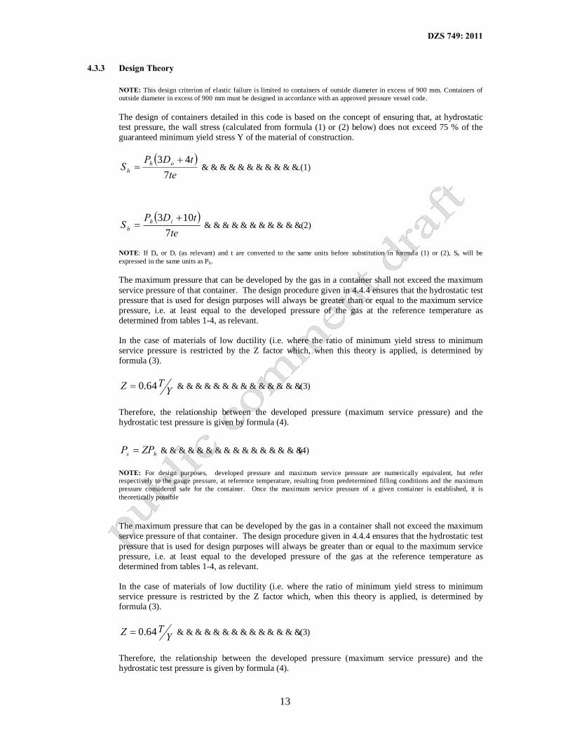
4.3.3 Design Theory
NOTE: This design criterion of elastic failure is limited to containers of outside diameter in excess of 900 mm. Containers of outside diameter in excess of 900 mm must be designed in accordance with an approved pressure vessel code.
The design of containers detailed in this code is based on the concept of ensuring that, at hydrostatic test pressure, the wall stress (calculated from formula (1) or (2) below) does not exceed 75 % of the guaranteed minimum yield stress Y of the material of construction.
( )te
tDPS oh
h 743 +
= ……………………………..(1)
( )te
tDPS ih
h 7103 +
= …………………………….(2)
NOTE: If Do or Di (as relevant) and t are converted to the same units before substitution in formula (1) or (2), Sh will be expressed in the same units as Ph. The maximum pressure that can be developed by the gas in a container shall not exceed the maximum service pressure of that container. The design procedure given in 4.4.4 ensures that the hydrostatic test pressure that is used for design purposes will always be greater than or equal to the maximum service pressure, i.e. at least equal to the developed pressure of the gas at the reference temperature as determined from tables 1-4, as relevant. In the case of materials of low ductility (i.e. where the ratio of minimum yield stress to minimum service pressure is restricted by the Z factor which, when this theory is applied, is determined by formula (3).
YTZ 64.0= …………………………………….(3)
Therefore, the relationship between the developed pressure (maximum service pressure) and the hydrostatic test pressure is given by formula (4).
hs ZPP = …………………………………………(4)
NOTE: For design purposes, “developed pressure and maximum service pressure are numerically equivalent, but refer respectively to the gauge pressure, at reference temperature, resulting from predetermined filling conditions and the maximum pressure considered safe for the container. Once the maximum service pressure of a given container is established, it is theoretically possible The maximum pressure that can be developed by the gas in a container shall not exceed the maximum service pressure of that container. The design procedure given in 4.4.4 ensures that the hydrostatic test pressure that is used for design purposes will always be greater than or equal to the maximum service pressure, i.e. at least equal to the developed pressure of the gas at the reference temperature as determined from tables 1-4, as relevant. In the case of materials of low ductility (i.e. where the ratio of minimum yield stress to minimum service pressure is restricted by the Z factor which, when this theory is applied, is determined by formula (3).
YTZ 64.0= …………………………………….(3)
Therefore, the relationship between the developed pressure (maximum service pressure) and the hydrostatic test pressure is given by formula (4).
DZS 749: 2011
14
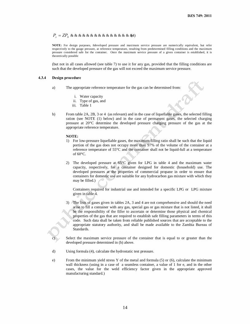
hs ZPP = …………………………………………(4)
NOTE: For design purposes, “developed pressure and maximum service pressure are numerically equivalent, but refer respectively to the gauge pressure, at reference temperature, resulting from predetermined filling conditions and the maximum pressure considered safe for the container. Once the maximum service pressure of a given container is established, it is theoretically possible (but not in all cases allowed (see table 7) to use it for any gas, provided that the filling conditions are such that the developed pressure of the gas will not exceed the maximum service pressure.
4.3.4 Design procedure a) The appropriate reference temperature for the gas can be determined from:
i. Water capacity
ii. Type of gas, and iii. Table 1
b) From table 2A, 2B, 3 or 4 (as relevant) and in the case of liquefiable gases, the selected filling
ration (see NOTE (1) below) and in the case of permanent gases, the selected charging pressure at 20°C determine the developed pressure charging pressure of the gas at the appropriate reference temperature.
NOTE:
1) For low-pressure liquefiable gases, the maximum filling ratio shall be such that the liquid portion of the gas does not occupy more than 97% of the volume of the container at a reference temperature of 55°C and the container shall not be liquid-full at a temperature of 60°C.
2) The developed pressure at 65°C given for LPG in table 4 and the maximum water
capacity, respectively, for a container designed for domestic (household) use. The developed pressures at the properties of commercial propane in order to ensure that containers for domestic use are suitable for any hydrocarbon gas mixture with which they may be filled.)
Containers required for industrial use and intended for a specific LPG or LPG mixture given in table 4.
3) The lists of gases given in tables 2A, 3 and 4 are not comprehensive and should the need
arise to fill a container with any gas, special gas or gas mixture that is not listed, it shall be the responsibility of the filler to ascertain or determine those physical and chemical properties of the gas that are required to establish safe filling parameters in terms of this code. Such data shall be taken from reliable published sources that are acceptable to the appropriate statutory authority, and shall be made available to the Zambia Bureau of Standards.
c) Select the maximum service pressure of the container that is equal to or greater than the
developed pressure determined in (b) above. d) Using formula (4), calculate the hydrostatic test pressure.
e) From the minimum yield stress Y of the metal and formula (5) or (6), calculate the minimum
wall thickness (using in a case of a seamless container, a value of 1 for e, and in the other cases, the value for the weld efficiency factor given in the appropriate approved manufacturing standard.)

DZS 749: 2011
15
h
ho
PYePD
t475.07
3−×
= ……………………………..(5)
h
hi
PYePD
t1075.07
3−×
= ……………………………(6)
NOTE: 1) For steel cylinders, wall thickness calculations shall be based on a value of Y that does
not exceed the appropriate of the following maxima:
Y, max Normalised, and normalised and tempered containers 0.75 T Quenched and tempered containers 0.90 T Containers of welded containers 0.80 T 2) If Ph and Y are converted to the same units before substitution in formula (5) or (6), t will
be expressed in the same units as Do and Di.
3) The minimum wall thickness as calculated in formula (5) or (6) is based on pressure considerations only, but an additional thickness may be required, e.g. to render the container suitable for normal handling or to provide a corrosion allowance. In order to establish this, the appropriate approved manufacturing standard must be consulted.
4.4 Special Purpose Containers a) Most special purpose containers are of light construction and operate at higher wall stresses than
conventional containers. A special-purpose container that has been approved by the appropriate statutory shall not be used for any purpose other than that specified in the manufacturing standard.
b) Portable LPG containers that are intended for general duty shall not be used for supplying fuel to
motorised vehicles. Containers shall be specially manufactured for this purpose in accordance with the relevant recommendations given in SANS 20067
c) No person shall manufacture or import dissolved acetylene cylinders for distribution unless he can produce proof to the satisfaction of the appropriate statutory authority that at least three cylinders that are representative of the cylinders to be manufactured or imported have been subjected to and have passed the test prescribed for prototype dissolved acetylene cylinders in SANS 220).
4.5 Re-Use/Change of Containers
a) A container may be re-used for the same service, provided that it is still in good condition and that it is inspected and tested in accordance with section 5 at the intervals given in Table 6.
b) A container may, subject to the limitations given in (c) and (d) below be transferred to a different service, provided that it is thoroughly clean and has been inspected and, when applicable, tested in
c) accordance with 5.3, and provided that the relevant markings and colour coding have been changed in an acceptable manner to comply with the requirements of section 4.
d) A cylinder equipped with a foot ring shall not be used for underwater service. e) A container that has been used for the storage of any coal produced gas (i.e. methane or carbon
monoxide), shall not be used for any other gas.
4.6 Repair of Containers
Major repairs of damage to containers (these include the removal of dents and repairs that involve the application of heat to any part of the pressure-resistant shell of a container) shall be undertaken only by
DZS 749: 2011
16
the original manufacturer or by an approved repair station. As is required of manufacturers of portable gas containers, the facilities and equipment available to repair stations shall be such as to enable the stations to produce repaired containers that comply an all respects with the requirements of the standard to which the original cylinder was manufactured.
The premises, facilities and quality management system employed by a repair station shall be approved by and remain under the supervision of a recognised inspection authority.
Repair stations shall make application to the appropriate statutory authority for permission to operate such a facility and, at the same time, shall register an identification mark that shall be stamped on each repaired container.
In order to ensure that the extent of any corrosion can be ascertained and that the correct heat treatment after repair can be applied, repairs that involve welding or heating (or both) of portions subject to pressure shall not be undertaken unless the original wall thickness, analysis of the material of construction and the heat-treatment conditions are known.
Before a repaired container is put back into service, it shall be subjected to the hydrostatic test pressure prescribed in the relevant manufacturing standard, and shall pass the test. Any repairs to a container shall be done in such a way that the repaired container will comply in all respects with the requirements of the standard to which it was manufactured.
Welding repairs shall not be carried out on a container that has been painted with a zinc paint or has been zinc–sprayed, until the zinc coating has been completely removed from the area that will be affected by the welding (i.e. the heat- affected zone). Damaged shells of domestic (household) containers of water capacity less than 11.5 litres shall not be repaired.
Under no circumstances shall seamless containers of any size be repaired.
Damaged or defective fittings such as valves and safety devices shall be repaired or be replaced by authorised fillers and users, manufacturers of cylinders and repair stations only. Retail distributors of LPG and inspection and testing stations may replace defective valves and removable shrouds.
4.7 Valves
4.7.1 General The valves shall be of a design suitable for the duty and service for which they are intended. All parts of the valves in contact with the contents of the containers shall be of material(s) that will not react with the gas or the metal of the container. Valves fitted to LPG containers shall comply with the requirements of ZS 429 and LPG cylinders shall have neck threads1 to match, within the allowed limits, the valve inlet threads specified in ZS 429.
1 For containers other than LPG containers, the following cylinder neck threads are recommended:
a) For class 1 steel cylinder intended for high-pressure industrial service, use a 1 in. Whitworth right-hand taper thread in accordance with BS 341, but for small diameter cylinders in this class, a 0.715 in Whitworth right-hand taper thread may be more suitable;
b) For class 1aluminium cylinders, use either a parallel thread in conjunction with an effective O-ring seal, or a thread as specified in (a) above for class 1 steel cylinders.
c) For class 2 and 3 cylinders of water capacity not exceeding 11.5 litres and intended for low-pressure liquefiable gas use a ½-NGT right-hand taper thread in accordance with SABS 199.
d) For larger class 2 and 3 cylinders of water capacity exceeding 11.5 litres and intended for low-pressure liquefiable gas use a ¾-NGT right hand taper thread in accordance with SABS 199.
e) For dissolved acetylene cylinders smaller than 10 litres, use a 0,715 in Whitworth right-hand thread and for cylinders larger than 10 l use a 1.0 in or a 1.025 in Whitworth right-hand taper thread in accordance with BS 341.

DZS 749: 2011
17
4.7.2 Protection of Valves Valves on tanks shall be adequately protected against mechanical damage. On a cylinder used of water capacity exceeding 10 litres (other than a cylinder used for diving and flammable or toxic or both) the valve shall be adequately protected by means of a detachable cap that can be securely attached to the cylinder, except that a cap is not required when the valve is set into a recess of the cylinder or is protected by a metal shroud attached to the cylinder body.
4.7.3 Pressure Regulators Any pressure regulator connected to an LPG cylinder shall comply with the requirements for low-pressure regulators for LPG, given in ZS 429.
4.8 Safety Devices
4.8.1 General Safety devices are intended to relieve pressure if a container is exposed to adverse conditions. Safety devices shall be of robust construction and capable of an accurate setting. All parts of a safety device shall be of material (s) that will not react with the contents or the metal of the container.
4.8.2 Type
a) General More than one type of safety device may be used and more than one device of the same type may, when so required, be used on one container. Spring loaded safety devices are prohibited on portable containers for Class A poisons but may be used on containers for other gases.
b) Spring-loaded safety valves A spring loaded safety valve shall be set (when installed on a container) to commence relieving pressure at the maximum service pressure of the container.
c) Frangible discs
i. Primary frangible discs Primary frangible discs shall be designed to rupture at the reference temperature of the maximum permissible operating pressure of the container.
ii. Secondary frangible discs
Secondary frangible discs shall rupture at a nominal pressure that is 10 % above the start-to-discharge pressure of the pressure relief device.
d) Fusible plugs A fusible plug shall contain a fusible alloy having a yield temperature of not lower than 96ºC and not higher than 110ºC. At ambient temperature the fusible plug shall withstand a pressure equal to the applicable hydrostatic test pressure (see 4.4.4 (d)).
4.8.3 Location of Safety Devices
a) On Cylinders If a safety device is fitted to a cylinder containing a liquefied gas, it shall be positioned that when the cylinder is in an upright position, gas or vapour will be vented in preference to liquid.

DZS 749: 2011
18
A cylinder containing chlorine shall have no opening other than that in the neck of the cylinder for the attachment of the valve. If a safety device is fitted, it shall be a fusible plug that is incorporated in the body of the valve.
b) On portable tanks A safety device on a portable tank shall be adequately protected against mechanical damage either by the way in which it is set into the tank or by being covered by a housing, the housing shall have an opening of area at least twice the total discharge area of the safety device(s) beneath the housing. A housing shall be so designed so as to withstand loadings (in any direction) equal to eight times the mass of the tank when filled with water and fitted with all other attachments.
4.9 Inspection Openings
The openings provided for the attachment of valves and safety devices are normally adequate for purposes of conducting internal inspections. However, in the case of a portable tank intended for a corrosive gas and that has, in the centre of a domed end, one threaded opening for the attachment of a valve, and unless the opening is large enough to permit satisfactory internal inspection, an additional (inspection) opening may be provided in the centre of the other domed end.
Such an inspection opening shall be taper-threaded and fitted with a plug or sealed by means of a bolted flange and gasket, and the closure shall be adequately protected against mechanical damage. The materials used for example, bosses, plugs and weld metal, shall be compatible with the material of the tank and resistant to attack by the gas.
5 MARKING, LABELLING AND CERTIFICATES
5.1 Permanent Marking on Containers 5.1.1 Existing containers.
Each existing container shall be legibly and durably marked (hard-stamped, embossed or embedded in the resin of composite containers) as required by the standard to which it was manufactured. In addition each existing container re-rated in terms of 10.3 shall be permanently marked with the appropriate adjusted Z factor and the hydrostatic pressure.
5.1.2 New containers.
In addition to the marking required by the standard to which the container was manufactured, the following information shall be legibly and permanently marked on each new container:
a) The name or recognised chemical symbol of the gas for which the container was designed; b) The hydrostatic test pressure, in kilopascals e.g. TP 15 000 kPa; c) The date of inspection and of the hydrostatic test (year and quarter); d) The Z factor used in terms of 3.4.3 or 9.2, as relevant, e.g. Z = 0.85; e) The guaranteed maximum water capacity in litres e.g. WC 39.2 l; f) In a case of a container for a permanent gas, the charging pressure in kilopascals; g) In a case of a container for a liquefiable gas, the tare mass, in kilograms; h) In a case of a container for a corrosive gas, the shell mass, in kilograms e.g. SM 50.2 kg, accurate
to within 0.5 % of the actual shell mass; i) The number of the standard3 to which the container was manufactured or, when relevant, and in a
case of a manufacturer outside Zambia, an identification code that enables the standard to which the container was manufactured to be identified;
j) the heat – treatment symbol, the appropriate of the following being used:
3 In terms of the Standards Act Cap 416 of the Laws of Zambia, it is a punishable offence for any person other than the holder of a permit issued by the Council of the Zambia Bureau Standards to refer to the Zambia Bureau of Standards for any of its specifications in a manner likely to create the impression that a commodity has been approved by the Zambia Bureau of Standards or complies with the requirements of the specification referred to.
DZS 749: 2011
19
N = normalised T = quenched in oil or other medium that has a cooling rate of not more than 80% that of water (without additives) at 20°C, and tempered W = quenched in medium having a cooling rate greater than 80% of that of water (without additives) at 20°C and tempered;
k) the inspection authority’s identification mark; l) the manufacturer’s identification mark;
m) the manufacturer’s serial number for the container;
n) the country of origin, indicated by the relevant alpha –2 country code given in ISO 3166.
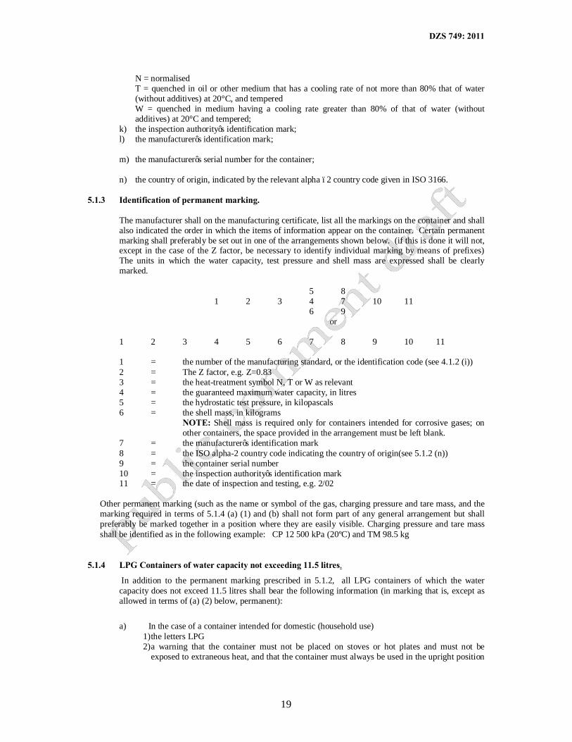
5.1.3 Identification of permanent marking.
The manufacturer shall on the manufacturing certificate, list all the markings on the container and shall also indicated the order in which the items of information appear on the container. Certain permanent marking shall preferably be set out in one of the arrangements shown below. (if this is done it will not, except in the case of the Z factor, be necessary to identify individual marking by means of prefixes) The units in which the water capacity, test pressure and shell mass are expressed shall be clearly marked.
5 8
1 2 3 4 7 10 11 6 9
or
1 2 3 4 5 6 7 8 9 10 11
1 = the number of the manufacturing standard, or the identification code (see 4.1.2 (i)) 2 = The Z factor, e.g. Z=0.83 3 = the heat-treatment symbol N, T or W as relevant 4 = the guaranteed maximum water capacity, in litres 5 = the hydrostatic test pressure, in kilopascals 6 = the shell mass, in kilograms
NOTE: Shell mass is required only for containers intended for corrosive gases; on other containers, the space provided in the arrangement must be left blank.
7 = the manufacturer’s identification mark 8 = the ISO alpha-2 country code indicating the country of origin(see 5.1.2 (n)) 9 = the container serial number 10 = the inspection authority’s identification mark 11 = the date of inspection and testing, e.g. 2/02
Other permanent marking (such as the name or symbol of the gas, charging pressure and tare mass, and the marking required in terms of 5.1.4 (a) (1) and (b) shall not form part of any general arrangement but shall preferably be marked together in a position where they are easily visible. Charging pressure and tare mass shall be identified as in the following example: CP 12 500 kPa (20ºC) and TM 98.5 kg
5.1.4 LPG Containers of water capacity not exceeding 11.5 litres.
In addition to the permanent marking prescribed in 5.1.2, all LPG containers of which the water capacity does not exceed 11.5 litres shall bear the following information (in marking that is, except as allowed in terms of (a) (2) below, permanent):
a) In the case of a container intended for domestic (household use)
1) the letters LPG 2) a warning that the container must not be placed on stoves or hot plates and must not be
exposed to extraneous heat, and that the container must always be used in the upright position

DZS 749: 2011
20
(use the appropriate symbol given in ZS 429) The container may be marked with this warning by means of a stencil or by means of marking on an adhesive label. (see Appendix D)
b) in the case of the container intended for industrial use, the name of the gas, e.g. “butane”
5.1.5 Additional permanent marking. Permanent marking to be stamped on containers (see 5.5.1) after
examination and testing shall include the following: a) the date ( year and quarter) to indicate that an internal inspection was conducted or the date
followed by the letter “H” to indicate that an internal inspection and a hydrostatic test were conducted;
b) the identification mark of the approved testing station (placed adjacent to the date); c) when relevant, the new tare mass.
5.1.6 Maintenance of permanent marking All marking applied in terms of 4.1 shall be maintained in a legible condition and shall not be obscured by paint.
5.2 COLOUR CODING OF CONTAINERS NOTE: The numbers given in brackets after the colours are the colour numbers of SABS 1091.
5.3.1 General In addition to the marking required in terms of 5.1 the outer surfaces of containers shall be
so painted as to have the appropriate colour marking given in 5.3 (Table 8) (inclusive) The width of each coloured shoulder band shall be at least one quarter of the outside diameter of the container body.
5.3.2 Cylinders for diving and surface rescue purposes. The body of a cylinder used for diving and
surface rescue purposes shall be canary yellow (C61) and the shoulder shall be french grey (H30). 5.3.3 Containers for commonly used industrial gases. Containers for the gases listed in table 8 shall be
colour marked as shown in the table. 5.3.4 Containers for gases for which specific colour markings have not been allocated. Containers for
gases for which specific colour markings have not been allocated shall be coloured as follows (except that cylinders used for LPG are not required to have the red shoulder band prescribed in (c) and (d) below):
a) The body of the container shall be coloured white, light grey (G29) or aluminium, and if, any other
colour is applied to the container for purposes of owner identification, the colour shall be such that there can be no confusion with colours and colour bands laid down elsewhere in 4.3.
b) If the gas is toxic and non-flammable, the container shall have a golden yellow (B49) shoulder band.
c) If the gas is non-toxic and flammable, the container shall have a golden yellow (B49) shoulder band.
d) If the gas is toxic and flammable, the container shall have a golden yellow (B49) shoulder band as well as a signal red (All) shoulder band. The red band shall be next to the neck and the yellow band shall be between the red band and the junction of the shoulder and the body.
5.3.5 Cylinders for medical gases.
Cylinders for medical gases shall be colour marked in accordance with SANS 10006. 5.3.6 Containers fitted with internal tubes.
A container fitted with a conventional type LPG vapour withdrawal valve that is connected to an internal eductor tube for liquid withdrawal shall be clearly marked to indicate the presence of the eductor tube. If such indication is given by colour coding, it shall not be in the form of a yellow or red shoulder band as prescribed for toxic and flammable gases (see 5.3.4 (d) ). In the case of container fitted with a dual purpose valve that has both vapour and liquid outlets, the liquid withdrawal outlet shall be clearly identified and the liquid and vapour outlets shall be non-interchangeable.
DZS 749: 2011
21
5.4 LABELLING
5.4.1 Dangerous-commodity labels
If a container has been filled with a dangerous commodity and is to be conveyed by public transport, it shall be labelled in accordance with ECZ regulations except that when the form of the container is readily visible, the container need not bear the compressed gas label. If the gas container is concealed in an outer box or other type of outer container the outer shall bear the “Compressed Gas Label and also the label.
5.4.2 Other labelling
In addition to the marking required in terms in terms of 5.1, 5.3 and, and when relevant, 5,4,1, each filled container shall bear a label that is securely attached to it and that provides the following information:
a) The name of the filler; b) The quantity of the contents as required by the Weights and Measures Act and its regulations; and c) In the case of LPG cylinder having a vapour withdrawal valve, a label of appropriate symbol given
in ZS 429 to indicate that the cylinder must be used in the upright position.
5.5 CERTIFICATES 5.5.1 General.
The owners of the containers (other than containers manufactured under the certification mark scheme of the Zambia Bureau of Standards, or diving cylinders owned by private individuals and clubs) shall be in possession of the usual manufacturing and inspection certificates (as supplied with new containers), covering each container that they own. One certificate may cover a batch of containers, provided that it clearly indicates the serial numbers of the containers covered. In the case of diving cylinders, the distributor shall retain the originals of all certificates applicable to cylinders sold to private individuals and clubs.
5.5.2 Manufacturing certificates. A manufacturing certificate shall clearly indicate the following:
a) The quantity of containers covered by the certificate; b) The manufacturer’s serial number (s) or the information required in terms of (c) below, or both; c) If so required by the purchaser, the owner’s serial numbers; d) The number of manufacturing standard or, when relevant, the identification code of the standard to
which the container was manufactured (see 5.1.2) (i) e) The manufacturer’s name, address and identification mark; f) The country of manufacture; g) The owner or purchaser’s name and address; h) The hydrostatic test pressure; i) The name of the gas for which the container is intended; j) If the container is for a permanent gas, the charging pressure at 20°C; k) The value of the Z factor marked on the container (see 5.1.2 (d) ) and the calculation
showing how it was derived; l) where relevant, the calculation of the adjusted Z factor, (see 10.3.3) m) in the case of a container intended for a liquefiable gas, the maximum filling ratio; n) the water capacity in litres; o) the length of the containers; p) the outside diameter of the container; q) the minimum wall thickness; r) when relevant, the thickness of the corrosion allowance; s) the drawing number t) the type and the chemical analysis of the material of construction u) the heat treatment and the quenching medium v) the guaranteed minimum yield stress w) the guaranteed minimum tensile strength

DZS 749: 2011
22
x) the permanent marking on each container and the sequence of marking In addition to the manufacturing certificate bearing the information listed above, a certificate bearing the following words shall be issued: “This is to certify that prototype containers made to drawing No….. and in exactly the same way as the containers covered by this certificate, have successfully passed the fatigue and destruction tests prescribed in subsection 4.4.2 of this ZS 749 Code of practice for portable metal containers for compressed gases: basic design criteria, use and maintenance
Signature of Manufacturer Date ……………………...” 5.5.3 Inspection certification. An inspection certificate shall clearly indicate the following:
a) the name, address and identification mark of the inspection authority b) the actual dimension of the containers in a representative sample c) the results of tests on the material for
1) yield stress 2) tensile strength 3) Elongation, 4) Charpy V-notch impact values at 20°C, -20°C and -30°C, and 5) Bending properties 6) Hardness.
In addition to the actual test results required in terms of (c) above, a certificate bearing the following words shall be issued: “This is to certify that the containers covered by manufacturer’s certificate No….. have passed the hydrostatic test and other tests and analysis required and that they are in accordance with Standard No………..”
6. INSPECTION AND TESTING OF CONTAINERS
6.1 Inspection and Testing Stations A container that requires periodic inspection and testing (see table 6 or special inspection and testing or re-rating, shall be inspected and tested (and suitably stamped at an approved container testing station.
NOTE: Inspection and testing stations are not authorised to carry out major repairs on gas containers (see 4.7) (major repairs includes the removal of the dents ad repairs that involve the application of heat to any part of the pressure-resistant shell of a container). Testing stations that demonstrate that their personnel are trained and experienced in inspection procedures and that the stations are equipped as prescribed may be approved by the appropriate statutory authority, to whom application for approval shall be made. A testing station that has been approved shall register its identification mark with the statutory authority, and all stamping on a container shall be endorsed with the identification mark. A testing station shall not inspect or test any container unless the testing station is in possession of an-up to-date copy of the latest edition of the standard covering the manufacturing details of the container, and has verified that the standard has been approved.
6.2 Documentation and Equipment An approved inspection and testing station shall have the following items of documentation and equipment:
DZS 749: 2011
23
a) A copy of this code of practice, copies of the statutory regulations and at least one set of standards
applicable to the containers that the testing station undertakes to test. Such documents shall be the latest editions and shall be kept up-to date with all current amendments.
b) Hydrostatic test apparatus capable of attaining and holding the test pressure of the container under test. The apparatus shall be fitted with a pressure gauge, graduated to read not more than twice the test pressure of the container. The pressure gauge shall be checked and calibrated once a month or as maybe required from time to time.
c) A pressure-gauge tester or a duplex master pressure gauge used for the calibration of working pressure gauges
d) Suitable equipment that permits the viewing of all internal surfaces of the containers, and good lighting for the examination of all external surfaces.
e) Straight-edges, templates and gauges for measurement, and the requisite miscellaneous tools f) Equipment for determining mass, together with assized mass g) Adequate container-cleaner equipment h) Adequate container –draining equipment i) Facilities for drying containers internally j) Marking and stamping equipment
6.3 Inspection and Test Procedures 6.3.1 General
a) A container shall be inspected externally every time it is received for filling. Any container due for periodic inspection (see table 6) or showing significant defects shall be sent to a testing station for thorough inspection and testing.
b) The testing station shall adopt procedures that ensure that the standard of inspection and testing of each container as adequate. If all the relevant marking on the container as required in terms of 5.1 is not present or is illegible, the container shall be condemned (see 6.4).
c) A container received at a testing station for either special inspection or periodic inspection according to the appropriate frequency prescribed in table 6, shall be subjected to the relevant of the following inspections and tests, carried out as detailed in 6.3.2-6.3.5 (inclusive):
6.3.2 External examination.
A container shall be examined externally for rust, scale, damage and other physical defects. Protective paint, plaiting or other coatings and foreign matter shall, where necessary, be removed from the outer surface of the container in order that the surface may be properly examined. Particular attention shall be paid to the bottom of the container and to the junction of the footring and the body. In determining the condition of the container, the examiner shall take into consideration the minimum wall thickness required by the standard to which the container was made.
Where it is evident from the condition of the paint on a container that the container has been exposed to fire, it shall be examined particularly carefully. If no distortion, cracking, warping, bulging or other damage is detected, the container shall be heat-treated and shall subsequently pass the hydrostatic test before it is accepted for further service. If distortion, cracking, warping or bulging is detected, the container shall be condemned.
NOTE: Appendix B defines various defects and makes recommendations for the rejection of containers, based on quantitative assessment of these defects. The appendix is intended as a guide to inspectors but it is emphasised that experience is an important factor in determining the acceptability of a given container for continued service.
6.3.3 Internal Examination
a) Valves and safety devices. All valves and threaded fittings shall be removed for inspection. Valves shall be tested and, if found to be defective, shall be dismantled, and components that are not in a serviceable condition shall be reconditioned or replaced, as necessary.

DZS 749: 2011
24
If safety devices are fitted, they shall be closely inspected and tested and, if found to be in any way unsound, they shall be reconditioned or replaced, as necessary. When threaded fittings are replaced, care shall be taken to ensure that threads are not strained unduly by over tightening.
b) Acetylene cylinders In the case of a cylinder filled with a non-monolithic material, the top of the
mass shall be examined 1 year after the monolithic mass has been placed, and thereafter at intervals of 2 years. Cavities shall be made good by adding the prescribed porous filling to the limit specified
c) by the manufacturer. In the case of a cylinder filled with a monolithic porous mass, the top of the mass shall be examined 1 year after the monolithic has been placed, and thereafter at intervals of 7 years.
If the porous filling is considered to be defective, it shall be removed and the cylinder shall be cleaned and the examined as in (c) and (d) below and, if it is acceptable, it may be recharged with porous filling and returned to service.
d) Cleaning. Where the interior of a steel container is contaminated by oil or other similar fluid, it
may be cleaned by steam injection or washing out with an acceptable solvent and, where the interior is contaminated by rust or other foreign matter, it may be cleaned by burning out in the furnace at a controlled temperature of not higher than 300 °C, after which all free rust and scale can be removed. A container may also be cleaned internally by means of an acceptable rumbling, blasting or rotary wire-brush method. If acid cleaning is employed, it shall be done under strictly controlled conditions to ensure that pitting or erosion (or both) of the metal is prevented.
e) Examination. The whole of the internal surface of the container shall be examined by means of a
suitable inspection lamp. The container shall be condemned if the bottom of an internal defect cannot be seen and its extent cannot be measured. If the thickness of container at any corroded area is less than the specified minimum wall thickness, follow the recommendations given in Appendix B.
f) Gas Leakage. When a leak is suspected, the container shall be submerged in water and pressurized
with air or subjected to a soap-bubble test. Repairs shall be undertaken in accordance with 4.7. NOTE: Before this test is undertaken, the container shall be emptied of any gas it may contain, and the air pressure applied shall not exceed the lesser of 700 Kgs and half the hydrostatic test pressure pressurized for the container.
6.3.4 Hydrostatic Test.
The hydrostatic test pressure applied shall be the pressure prescribed by the manufacturing standard (and that may be permanently marked on the container). As soon as the test pressure is reached, the supply valve shall be closed and, before the pressure is released, sufficient time (as prescribed in the applicable manufacturing code) shall be allowed to give a clear indication whether or not the container is expanding or leaking. After hydrostatic testing, a container shall be emptied and completely dried before the valve is replaced. NOTE: Hydrostatic testing is called for after a) a container has been manufactured; b) the period of time prescribed in table 6 for the type of container and type of gas has expired; c) a container has been reheat-treated; d) a container shows defects that require verification by testing; e) a container has been repaired f) a container has been re-rated
6.3.5 Mass Determination
A container shall be empty and clean before tare mass or shell mass determination is undertaken.

DZS 749: 2011
25
6.4 Condemned Containers If a container fails to pass any one of the above tests, and cannot be repaired in accordance with 4.7, the owner shall be informed and the container destroyed.
6.5 Stamping and Records 6.5.1 Stamping
If the container complies with an approved standard, the testing station shall stamp the container with its own identification mark (registered with the appropriate statutory authority), the date of the examination and, if relevant (see 5.1.5), the letter “H” to indicate that a hydrostatic test was carried out.
NOTE: The container must not be stamped on its parallel section as this constitutes a defect (see table B-1). Information that must be stamped on a diving cylinder after internal inspection may be stamped on a robust and corrosion resistant metal disc that has the cylinder serial number stamped on it and that can be secured to the threaded boss when the valve is screwed to the cylinder. Stamping that is required on diving cylinders after hydrostatic testing shall, however, be stamped on the cylinder shoulder. If any of the masses marked on the container have altered (through repair or replacement of components) the new masses shall be marked on the container. Previous marking that may be needed to determine the extent of corrosion shall not be altered or obliterated.
6.5.2 Records
Testing stations shall keep records of all the results of examination of and tests on all containers that are not their property. A testing station shall also keep a written record of examination of and tests performed on all containers that are used for toxic and corrosive gases, and of the results of such examination and tests on all containers subjected to mass verification. Test reports issued to owners shall in each case contain the following information: a) the report serial number and date; b) the identification marks on the container c) the results of the examination of and the hydrostatic test on the container; d) the date of the examination: e) the details of repairs, reheat-treatment, alterations to marks and marks added to the container; f) a statement to the effect that the container complies with the relevant standard; and g) the signature of the responsible official.
6.6 Repainting When a container has been inspected or tested, it shall, if necessary, be re-painted in the appropriate colours (see table 8). Any decorative coating that requires heating of the cylinder during its application shall not be used on aluminium cylinders.
7 FILLING OF CONTAINERS
7.1 General The gases or mixtures of gases listed in tables 2A, 3 and 4 may be filled into and transported in cylinders or portable tanks. The purity and the moisture content of gases shall be acceptable. When a cylinder is filled for sale, the requirements of the Weights and Measures Act Cap 403 of the Laws of Zambia and its regulations shall be observed. Special attention shall be paid to the precautions given in 7.6.
7.2 Persons Competent To Fill Containers 7.2.1 General
No one shall fill a portable container with gas unless

DZS 749: 2011
26
a) he is fully conversant with the relevant subsections of this code; b) he is satisfied that the container complies with the requirements of an approved manufacturing
specification or the provisions of an approved manufacturing code (if necessary, this may be ascertained from the relevant container documents);
c) he employs staff trained and experienced in the filling of containers with those gases that he handles; and
d) the container is not due for periodic inspection or testing (see Table 6) 7.2.2 Liquefied Petroleum Gas
No one shall fill any container with LPG unless they have been authorised to do so by the relevant approving authority. The provisions of ZS 429 Part 3 shall apply.
7.3 Inspection before Filling Before filling any container, the filler shall ensure that;
a) the container is clean and free from obvious contaminants; b) the container complies with the requirements of an approved specification or the provisions of an
approved manufacturing code (if necessary, this may be ascertained from the relevant container documents); NOTE: Any container showing significant defects (see appendix B) shall be sent to a testing station for inspection and testing.
c) the container is not due for periodic inspection or testing (see Table 6; and d) the container, valves and safety devices (if any) are in good serviceable condition.
7.4 Filling With Permanent Gases 7.4.1 Pressure Relationships.
The permanent gases are listed in table 2A. The charging pressure at or corrected to 20°C shall be such that the developed pressure of the gas at 65°C (see table 2B) will not exceed the maximum service pressure for which the container was designed. The relationship between the developed pressure at reference temperature, the maximum service pressure and the hydrostatic test pressure of the container is given by the formula; NOTE: The charging pressure, the hydrostatic test pressure and the Z factor are permanently marked on the container.
7.4.2 Checks after Filling with Permanent Gases
a) After it has been filled, the container shall be carefully tested for leaks and, if a leak cannot be stopped by the tightening of spindles or gland nuts, the container shall be emptied and shall not be refilled until the cause of the leak has been rectified.
b) To ensure that the provisions of 7.4.1 have been complied with, the pressure of a container representative of those filled under the same filling conditions shall be checked after steady temperature conditions have been reached.
7.5 Filling With Liquefiable Gases 7.5.1 Additional Checks before Filling. In addition to carrying out inspection required in terms of 7.3, the
filler shall ascertain the maximum service pressure, the tare mass and the water capacity of the container and by, reference to table 3.4 or 5, that calculate the maximum permissible mass of gas that can be filled into the container
The relationship between the developed pressure at reference temperature (Pd), the maximum service pressure (Ps) and the hydrostatic test pressure (Ph) of the container is given by the formula: Pd ≤ Ps = Z Ph NOTE: The hydrostatic test pressure and the Z factor are permanently marked on the container.

DZS 749: 2011
27
See also NOTE (1) to 4.4.4
7.5.2 Filling with Liquefied Petroleum Gas (LPG) NOTE: See also the restrictions laid down in 7.2.2
The composition of mixtures of LPG will vary from case to case as the mixtures may consist wholly of saturated, partly of saturated and partly of unsaturated, or wholly of unsaturated hydrocarbons. To enable the correct filling of such mixtures into containers, the liquid density4 of the hydrocarbon gas mixture at 20°C is required. The maximum filling ratios for the whole range of practical values of liquid densities at 20°C are given in Table 5. If the density of the liquid hydrocarbon gas mixture is not known, it shall be determined by means of IP Method 432/2000.
7.5.3 Checks after Filling with Liquefiable Gases. After it has been filled, the container shall be tested in
accordance with 7.4.2 (a), and the mass of each filled container shall be checked after it has been disconnected from the charging line.
7.6 Precautions for Specific Gases 7.6.1 Corrosive Gases
a) Additional inspection before filling. In addition to the inspection of the container s required in terms of 7.3 (and, when relevant, 7.5.1), the valves shall be dismantled and, if necessary, reconditioned, and the filler shall determine whether the shall mass of the container tallies with the marking on the container. In the case of the container with no corrosion allowance (see 5.5.2 (r)), if the shell mass is 2.5 % (or more) less than the marked mass, the container, even if not due for inspection and testing, shall be submitted for inspection and testing in accordance with the appropriate parts of Section 6. If the container is found to comply in all respects with the relevant standard, it may be recharged.
b) General. The appropriate provisions of 7.4 or 7.5 (depending on whether the corrosive gas is a permanent gas or a liquefiable gas) shall apply.
7.6.2 Hydrogen Cyanide. The maximum mass of gas that may be charged into a container shall be 70kg.
After filling, the filler shall check the container for freedom from leaks by the application of a suitable indicator, e.g. a piece of moist Guignard (sodium picrate impregnated) paper, to all points of possible leakage.
7.6.3 Phosgene The maximum mass of gas that may be charged into a container shall be 70kg. After they
have been filled, containers of phosgene shall be completely immersed in water at a temperature of 65°C for at least 30 min, and examined for leakage.
7.6.4 Boron Trifluoride. When boron triflouride is filled into a container made in accordance with a
standard based on the principles given in this code, the maximum charging pressure shall not exceed 60 % of the maximum service pressure of the container.
When boron trifluoride is filled into an existing container manufactured in accordance with a standard not based on the principles given in this code and designed to be filled with permanent gases at a pressure of 13,900 kPa at 20°C (13,650 kPa at 15° C), the maximum charging pressure at 20°C shall be 10,400 kPa.
7.6.5 Fluorine The mass of fluorine filled into any container shall not exceed 5.5 kg, the pressure at 20°C
shall not exceed 2,800 kPa, and the maximum service pressure of the container shall be at least 18,600 kPa.
7.6.6 Acetylene
a) Additional checks before filling. In addition to carrying out the inspection required in terms of 7.3, the filler shall inspect the cylinder as follows:
4 The figure given by the supplier as the minimum density of any batch of the particular mixture

DZS 749: 2011
28
1) When there is no internal pressure The mass of the cylinder and contents shall be determined and compared with the original tare mass) stamped on the cylinder. If there is a difference in mass, this difference shall be regarded as the approximate acetone shortage.
2) When there is internal pressure. The approximate mass of acetylene in the cylinder in excess
of that included in the tare mass) of the cylinder shall be calculated from the pressure reading and other relevant cylinder data. The mass of the cylinder and contents shall be determined and this, less the calculated mass of the excess acetylene, shall be compared with the original tare mass stamped on the cylinder. If there is a difference in mass, this difference shall be regarded as the approximate acetone shortage6).
b) Acetone Replenishment before filling Cylinders in which the acetone shortage is more than 3% of the total required acetone content (see (c) below) shall be replenished with a quantity of acetone equal to the shortage.
c) Filling ratio The ratio of the mass of acetylene (including saturation gas) to the mass of the acetone shall be determined by the manufacturer, and the nominated maximum ratio may not be exceeded without approval based on a prototype evaluation. The equilibrium pressure at or corrected to 20°C shall not exceed 2 000 kPa
d) Checks after filling After it has been filled, the cylinder shall be tested as in 7.4.2. 7.6.7 Compressed Air for self-contained Breathing Apparatus
a) Additional checks before filling In addition to carrying out the inspection required in terms of 7.3, the filler shall ensure that no cylinder equipped with a footring is used for underwater service (see 4.6 (c), and that the cylinder is not due for periodic inspection or testing or both (see table 6) If the cylinder has a detachable boot, the filler shall remove the boot and inspect the bottom of the cylinder for signs of external corrosion.
b) Filling. In addition to those given in 7.4, the following provisions shall apply: 1) if the air supplied is from a compressor, the air so supplied shall be guaranteed as suitable for
respiration in accordance with the requirements of (2) below. 2) Air filled into a cylinder shall have been filtered, shall be odourless (see NOTE (i) below) and
shall have an oxygen content (see NOTE (ii) below) of 20-22 %(V/V), and any impurities present shall not exceed the relevant maxima given in table 9 (see NOTE (iii) below)
NOTE:
i) the average limit of oil that can be smelled is approximately 0.3 mg/m³. ii) Determined in accordance with the method given in the current European Pharmacopoeia but
with the use of a gas burette graduated from 1-100cm³. iii) The methods given in table 9 are the laboratory and reference methods. Recommended field
test methods are given in Appendix D. 3) When other gas mixtures are required for special underwater conditions, the composition of
the contents shall be stencilled on the cylinder. 4) The method of determining the amount of each constituent of the gas present in the cylinder is
given in Table 9.
c) Details to be recorded when a cylinder is filled. For each cylinder filled, the filler shall keep a record with the following information: 1) the date of filling 2) the name and address of the owner 3) the origin of the cylinder and the serial number 4) the date of the latest examination (see 6.5.1) 5) the type of gas filled into the cylinder 6) the charging pressure.
6 An example of the calculation to determine the acetone shortage is as follows: Tare mass stamped on cylinder 60 kg Actual mass of cylinder and contents 62 kg Mass of excess acetylene determined by calculation 3 kg ∴ Actual tare mass of cylinder less excess acetylene 59 kg ∴ Acetone shortage 1 kg
DZS 749: 2011
29
7.6.8 Class A Poisons
(See Tables 2A and 4). Class A Poisons shall not be filled into cylinders of welded construction unless acceptable special radiographic inspection has been undertaken.
7.7 Filling Of Containers Already In Use A container already in use shall not be filled other than in accordance with the details stamped on it unless an application for the container to be re-rated in accordance with the principles embodied in this code has been approved by the appropriate statutory authority. (see 10.3 and Appendix B
7.8 Filling of Cylinders Transferred To A Different Service
When a container is transferred to a different service, the filler shall ensure that the developed pressure of the gas at reference temperature does not exceed the maximum service pressure of the container and that the container is of a class suitable for the gas (see table 1 and ISO 11621 and ISO 11622).
7.9 Filling Of Containers for Use outside Zambia A container that is owned by a person not resident in Zambia and that will not be used in Zambia may be filled provided that:
a) it has marks that establish its hydrostatic test pressure and its charging pressure or filling ratio, and b) unless it can be identified as not being due for periodic inspection (see table 6), it is sent to a
testing station for thorough inspection and except in the case of an acetylene cylinder, hydrostatic testing.
8 HANDLING, STORAGE, TRANSPORTATION AND USE
8.1 Handling
Containers should be handled with care and shall not be subjected to any undue shock. Care should be taken to avoid any damage to the container and the valve.
8.1.1 Containers should not be dropped (for example from lorry tailboards) and shall be handled carefully by
avoiding sliding, rolling and skidding as far as is practicable. 8.1.2 Containers shall not, unless special equipment is used, be lifted by their valves, magnet lifting devices
shall not be used, and rope or chain slings shall not be used unless adequate provision is made for the attachment of the slings to the containers.
8.1.3 Ccontainers that cannot be handled by hand should be transported by hand trolley. 8.1.4 Filled containers should always be handled, transported and used in a secured, upright position.
8.2 Stacking 8.2.1 General.
The maximum height of any stack shall be governed by the stability of the stack and the ease with which containers can be safely placed on or removed from the stack. When gas in a container is in liquid form and the container is fitted with one or more safety devices, the container shall be so stacked that a safety device will leverage gas and not liquid.
8.2.2 Rules for Stacking Cylinders for Liquefied or Dissolved Gas
a) All compressed gas cylinders containing liquid shall be stored in a vertical position, resting on
their footrings or specially formed bases. b) Empty cylinders shall preferably be stored in a vertical position but may be stacked horizontally. c) Cylinders that are stored vertically (i.e. Cylinders that contain liquid or are empty) shall be
stored in single tier rows. d) Cylinders that are stored vertically may be arranged in groups each containing up to four rows of
cylinders, with gangways between groups.

DZS 749: 2011
30
e) When empty cylinders are stored horizontally, they shall be in single rows or in groups comprised of two rows with the valves adjacent to the gangways. The ends of each horizontal row shall be securely wedged.
f) Gangways shall be maintained between stacks, wall and fences g) When pallets or baskets are used, they shall be placed in single rows with gangways between the
rows.
8.3 Storage 8.3.1 General.
The storage area for LP Gas cylinders has to be approved by relevant authorities (refer to ZS 429 Part 3). Containers shall be stored in a dry place and away from boilers, open flames, steam pipes and any other source of heat or potential source of heat. They shall not be exposed to corrosive vapours. Containers of compressed gas shall not stored with flammables in other types of container. Cylinders for underwater use shall be stored in the valve-up position.
8.3.2 Reduction of hazards caused by leakage. In view of the possibility of leakage as a result of minor defects, containers shall be stored in suitably
ventilated areas. In the case of gases heavier than air, care shall be taken to ensure that drains or trenches do not create pockets in which gas may collect. If a leaking container is found and the leak cannot be stopped easily and quickly, the container shall be moved immediately to that part of an open space where it is least dangerous to life and property, and both the supplier and the filler shall be notified.
8.3.3 Empty containers
Empty containers shall be stored separately from full containers and care should be taken that valves are properly closed.
8.3.4 Compatibility in storage
Although compressed gas containers are more robust than most other packs for dangerous goods, they shall not be mixed indiscriminately in storage.
8.3.5 The storage area Should be kept clean and free from any combustible matter, such as paper. Any possible source of ignition should be removed. An area of at least 3 meters in all directions round the
8.3.6 Perimeter of the storage area 8.3.7 should be kept clear of grass, weeds and other combustible matter. Gangways should be provided and
should be wide enough.
8.3.8 Safety Precautions. Safety requirements for storage of LP Gas cylinders as defined in ZS 429 Part 3
8.3.9 The storage area for LP Gas cylinders may have a roof, provided that it is of fire-resitant construction and that it is at least 2.5 meters above floor level
8.3.10 Additional General Precautions. Adequate fire fighting equipment shall be available (see ZS 385 Part 1 and ZS 429 Part 3) and personnel shall be instructed in its correct use. In the case of toxic gases, personnel shall also be instructed in the correct dosage and usage of the appropriate antidotes. Gas masks and gloves may be required when certain gases are handled.
8.4 Transportation 8.4.3 Mixed Transportation. Containers shall be transported in accordance with the regulations of the
relevant transportation authority.
DZS 749: 2011
31
8.4.4 General Transportation
a) Any vehicle used to transport LPG cylinders should: i. Be suitable for the task, of adequate strength and in good condition.
ii. Permit the cylinders to be transported in the upright position. iii. Be open (preferred) or have adequate ventilation.
All loads should carry correct documentation showing the following; i. The UN number, proper shipping name, class and Tunnel Code (unless it is known
ii. the transport operation will not pass through a coded tunnel) in the format - iii. The quantity of each size and type (Propane or Butane) of each cylinder carried. iv. The consignors name and address. v. The consignee/s name/s and address/es - if not know insert the words "Delivery Sale"
b) when gas containers are packed in an outer container, the pack shall comply with the relevant requirements of Road Traffic Act
c) Containers transported in a vehicle shall be so blocked or braced (or both) as to prevent movement and shall not project beyond the sides or end of the vehicle. Tanks shall be secured in cradles. All containers for LPG shall be stacked in a vertical position during transportation.
d) In no instance shall containers be so loaded into a vehicle that they may bounce or may strike other objects. There shall be no sharp projections on the inside of the vehicle, and adequate measures shall be taken to prevent containers from falling off the vehicle.
e) Drivers and members of the vehicle crew are not permitted to smoke in or near any vehicle that is being loaded or unloaded with or transporting LPG cylinders.
f) Driver training and instructions shall be as outlined in ZS 429 Part 4 and ZS 372 g) Means of ignition i.e. cigarette lighters, lanterns, potable cooking stoves, etc are not permitted to be
carried or operated on or in the vehicle. h) Appliances may be carried as long as they cannot be operated whilst they are on the vehicle and their
carriage does not present a risk of ignition. Appliances that are boxed or packaged would comply with this requirement.
i) Apart from members of the vehicle crew no passengers should be carried
8.4.5 Leaking Containers. No leaking container shall be transported. If a leaking container is found it shall be dealt with in accordance with 8.3.2
8.4.6 If there is a smell of gas;
i. Do not move the vehicle until the source of the leakage has been found and the vehicle has been declared safe by a competent person.
ii. Increase the load compartment ventilation by fully opening all doors and vents. iii. Do not turn on any electrical equipment.
8.5 Use 8.5.3 General
Containers shall be adequately supported during use. Trolleys and cradles shall, where practicable, be used when containers are moved.
8.5.4 Acetylene Cylinders. If, when the valve of an acetylene cylinder is opened, the contents gauge shows
a pressure exceeding 4,000 kPa, or if the cylinder is heated accidentally or becomes unduly warm because of backfiring, or if there is any sign of smoke or any unusual smell from discharged gas, the cylinder shall be dealt with promptly either as instructed by the filler or as follows;
Immediately close the valve fully, evacuate personnel from the area and where possible, spray the cylinder with water from a hose-pipe operated from a safe distance and from behind cover. The supplier of the cylinder shall be consulted immediately.
DZS 749: 2011
32
9 GENERAL SAFETY PRECAUTIONS
9.1 Containers Exposed To Fire 9.1.1 General.
Containers that have been exposed to fire shall be dealt with in accordance with 6.3.2.
9.1.2 Acetylene Cylinders. The porous filling of acetylene cylinders that have been exposed to fire or have been on fire internally shall be removed, and the cylinders shall be dealt with as described in 6.3.2. If found to be satisfactory after reheat-treatment and retesting, the cylinders may be refilled with new porous filling. If, however, the cylinders are found to be unsatisfactory they shall be destroyed and care shall be taken to avoid ignition of the contents.
9.1.3 Precautions for corrosive gases
In addition to the inspection of the container as required in terms of 7.6.1, the valve functionality shall be checked and, if necessary, the valve shall be reconditioned or replaced.
9.1.3 The protection against fire and electrical hazards for vehicle carrying compressed gas cylinders Should comply with the provisions of ZS 429 Part 4
9.1.5 Warning Notices. Each vehicle shall display at least two notices, one on each side of the vehicle, that are painted on or securely attached to the sides of the vehicle and that consist of the following words or of the corresponding pictogram (i.e. Types PV1, PV2 and PV3) given in SANS 1186: DANGER - NO SMOKING - NO NAKED LIGHTS – SWITCH OFF CELL PHONE Printed in black letters on a yellow background (see also SANS 10140) and in English, in
letters of height at least 60 mm in the case of the word ‘DANGER’ and of height at least 30 mm in the
case of the remainder of the wording. (Warning Signs)
9.2 Inspection
The roadworthiness of the vehicle shall be checked daily as per Road Traffic Act No.11, 2002, an example of a checklist is given in Annex A
9.3 Valves No lubricant other than one approved by the filler shall be applied to threads or spindles of valves.
9.4 Position and Support Of Containers In Use Cylinders containing liquefiable gases and cylinders containing dissolved acetylene shall always be used in the normal and intended position for gas (vapour or liquid) withdrawal and when relevant shall be so supported that they cannot be knocked over. Cylinders that may be used in a horizontal position shall be so secured that they cannot roll. If portable tanks are still on their transportation cradles, they shall be so secured that they will not move.
9.5 REPORTING OF INCIDENTS
All uncontrolled container failures shall be reported to the appropriate approving authority. Uncontrolled failures of containers occurring at test and filling stations shall be recorded by them, subject to investigation by the appropriate approving authority.

DZS 749: 2011
33
10 APPROVAL OF FOREIGN STANDARDS, RATING OF CONTAINERS MADE TO FOREIGN STANDARDS AND RE-RATING OF EXISTING CONTAINERS
10.1 Approval of Foreign Standards and Containers Made To Foreign Standards 10.1.1 General.
Only containers that have been manufactured in accordance with standards that have been approved by the appropriate statutory authority will be allowed for general use in Zambia. Manufacturing standards and containers made to them will normally be approved only if the specified materials of construction and resistance to fatigue of the containers are in accordance with the provisions of this code and if the containers are rated for filling purposes at or below the limits given in this code. However, containers of the special purpose type that are rated above such limits may be accepted by the appropriate statutory authority, provided that they are not used for any purpose other than that specified in the manufacturing standard. In all cases, application must be made to the appropriate statutory authority.
10.1.2 Application for Approval.
An application to the appropriate statutory authority for the approval of a foreign standard and containers made to this standard shall be accompanied by:
a) a complete and up to date copy of the standard in English; b) the name and address of the manufacturer; and c) a statement by that
1) the manufacturer is in possession of an up to date copy of this code of practice and understands the contents.
2) that the material of the containers manufactured are within the parameters laid down in 4.4.1 and that prototypes manufactured have passed one of the fatigue tests given in 4.4.2 and
3) that the containers intended for the Zambian market will be rated for filling purposes as laid down in 10.2 and that this rating will not be higher than the limiting value ZA as determined in 10.3.3.
10.2 Procedure for Rating of Containers Produced According To Approved Foreign Standards (Determination Of The Z Factor) The hydrostatic test pressure for the container, prescribed in the manufacturing standard, multiplied by the Z factor to be marked on the container, must determine the maximum service pressure intended by the manufacturing standard. The developed pressure of the gas at the appropriate reference temperature (see table 1), i.e. the maximum service corresponding to the charging pressure at 20°C (see tables 2A and 2B) or to the maximum filling ratio (see table 3 and 4), and the value of the hydrostatic test pressure prescribed in the manufacturing standard must be used to calculate the Z factor from the following formula:
h
s
PP
Z =
This value of Z as calculated by the manufacturing shall, except in the case of special-purpose type containers (see 10.1.1), in no case be higher than the value of ZA determined in accordance with 10.3.3. Containers rated higher than the limiting value ZA must be re-rated by the manufacturer to be equal to this limiting value. Containers that are rated lower may not be rated higher by the manufacturer.
10.3 Re-Rating Of Existing Containers 10.3.1 General.
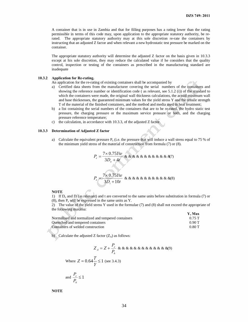
DZS 749: 2011
34
A container that is in use in Zambia and that for filling purposes has a rating lower than the rating permissible in terms of this code may, upon application to the appropriate statutory authority, be re-rated. The appropriate statutory authority may at this sole discretion re-rate the containers by instructing that an adjusted Z factor and when relevant a new hydrostatic test pressure be marked on the container.
The appropriate statutory authority will determine the adjusted Z factor on the basis given in 10.3.3 except at his sole discretion, they may reduce the calculated value if he considers that the quality control, inspection or testing of the containers as prescribed in the manufacturing standard are inadequate
10.3.2 Application for Re-rating.
An application for the re-rating of existing containers shall be accompanied by a) Certified data sheets from the manufacturer covering the serial numbers of the containers and
showing the reference number or identification code ( as relevant, see 5.1.2 (i)) of the standard to which the containers were made, the original wall thickness calculations, the actual minimum wall and base thicknesses, the guaranteed minimum values for the yield stress Y and the tensile strength T of the material of the finished containers, and the method and media used in heat treatment;
b) a list containing the serial numbers of the containers that are to be re-rated, the hydro static test pressure, the charging pressure or the maximum service pressure or both, and the charging pressure reference temperature;
c) the calculation, in accordance with 10.3.3, of the adjusted Z factor. 10.3.3 Determination of Adjusted Z factor
a) Calculate the equivalent pressure Pe (i.e. the pressure that will induce a wall stress equal to 75 % of the minimum yield stress of the material of construction from formula (7) or (8).
tD
YtePo
e 4375.07+
×= ………………………………(7)
tD
YtePi
e 10375.07+
×= ……………………………….(8)
NOTE 1) If Do and Di (as relevant) and t are converted to the same units before substitution in formula (7) or (8), then Pe will be expressed in the same units as Y. 2) The value of the yield stress Y used in the formulae (7) and (8) shall not exceed the appropriate of the following maxima:
Y, Max Normalised and normalized and tempered containers 0.75 T Quenched and tempered containers 0.90 T Containers of welded construction 0.80 T
b) Calculate the adjusted Z factor (ZA) as follows:
h
eA P
PZZ += ………………………………….(9)
Where 164.0 ≤=YTZ (see 3.4.3)
and 1≤h
e
PP
NOTE

DZS 749: 2011
35
1) If 1>h
e
PP
, the statutory authority will determine the value of the test pressure to be marked on the
container and to be used in the calculation of ZA. 2) The design data for the container ends must also be checked to ensure that at the calculated
equivalent pressure the ends are not stressed in excess of 75% of the minimum yield stress of the material of construction.
10.3.4 Marking of Re-rated Containers.
The adjusted Z factor, the new charging pressure at 20˚C and when relevant, the new hydrostatic test pressure shall be marked on the container, the adjusted Z value being followed by the letter R, e.g. Z = 0.85 R. Restamping shall be undertaken by an approved testing station only.
TABLE 1 – REFERENCE TEMPERATURES
1 2 3 4
Water capacity of container, litres
Reference temperature for developed pressure,
˚C
Liquefied gases Permanent gases
Low pressure
High pressure
0.5 up to but not including 150 150 to 1,000 inclusive Greater than 1,000 up to and including 1,200 1,200 up to and including 3000
65
62.5
60 ?
62.5
62.5
60 ?
65
65
65 ?
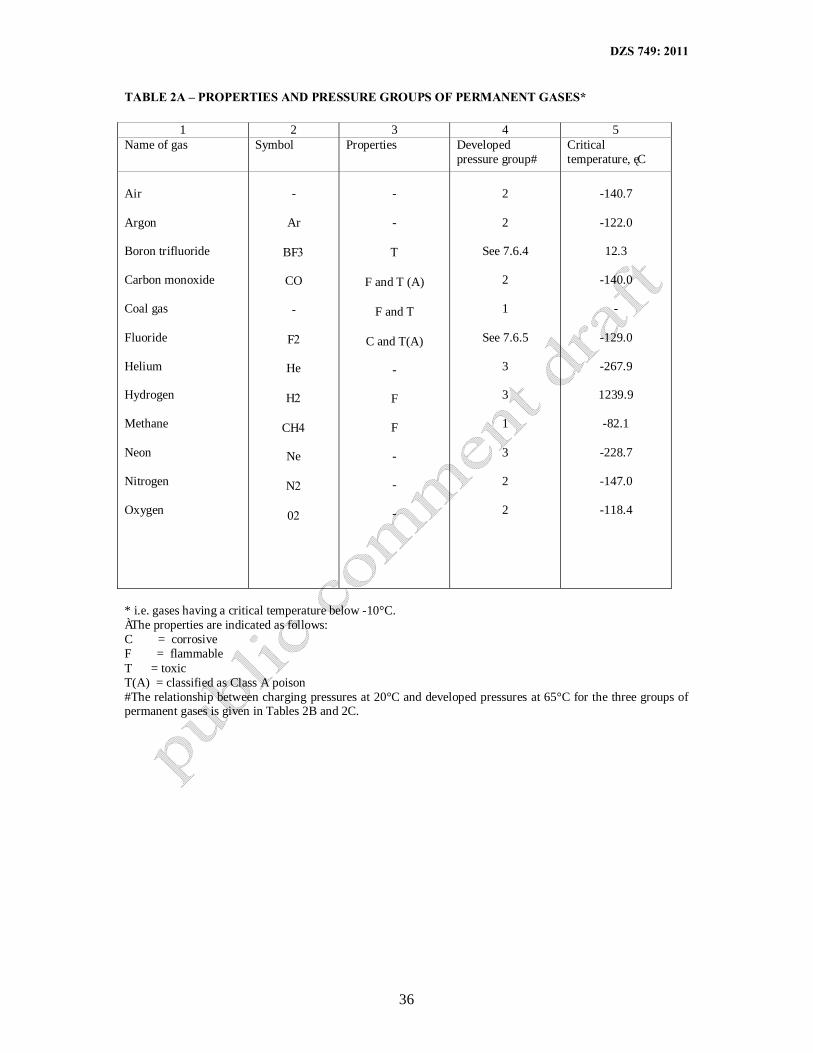
DZS 749: 2011
36
TABLE 2A – PROPERTIES AND PRESSURE GROUPS OF PERMANENT GASES*
1 2 3 4 5 Name of gas Symbol Properties† Developed
pressure group# Critical temperature, ˚C
Air Argon Boron trifluoride Carbon monoxide Coal gas Fluoride Helium Hydrogen Methane Neon Nitrogen Oxygen
-
Ar
BF3
CO -
F2
He
H2
CH4
Ne
N2
02
- -
Τ
F and Τ (A)
F and Τ
C and Τ(A) -
F
F - - -
2
2
See 7.6.4
2
1
See 7.6.5
3
3
1
3
2
2
-140.7
-122.0
12.3
-140.0
-
-129.0
-267.9
1239.9
-82.1
-228.7
-147.0
-118.4
* i.e. gases having a critical temperature below -10°C. †The properties are indicated as follows: C = corrosive F = flammable T = toxic T(A) = classified as Class A poison #The relationship between charging pressures at 20°C and developed pressures at 65°C for the three groups of permanent gases is given in Tables 2B and 2C.

DZS 749: 2011
37
TABLE 2B – PERMANENT GASES: CHARGING PRESSURES AND CORRESPONDING DEVELOPED PRESSURES
1 2 3 4
Charging pressure at 20°C,kPa
Developed pressure at 65°C, kPa (gauge)*
Group 1 Group 2 Group 3 2,000 4,000 6,000
8,000
10,000 12,000
14,000 16,000 18,000
20,000 22,000 24,000
26,000 28,000 30,000
2,300 4,800 7,500
10,200 12,900 15,700
18,600 21,400 24,300
27,200 30,200 33,100
36,100 39,100 42,100
2,300 4,800 7,200
9,700
12,200 14,700
17,200 19,800 22,300
24,800 27,400 30,000
32,500 35,100 37,600
2,300 4,600 7,000
9,300 11,600 13,900
16,200 18,600 20,900
23,200 25,500 27,900
30,200 32,500 34,800
*Values for charging pressures other than those given in column 1 may be obtained by linear interpolation.

DZS 749: 2011
38
TABLE 2C – PERMANENT GASES: DEVELOPED PRESSURES AND CORRESPONDING CHARGING PRESSURES
1 2 3 4
Developed pressure at 65°C, kPa (gauge)
Charging pressure at 20°C, kPa *
Group 1 Group 2 Group 3
2,000 4,000 6,000
8,000 10,000 12,000
14,000 16,000 18,000
20,000 22,000 24,000
26,000 28,000 30,000
32,000 34,000 36,000
38,000 40,000 42,000
1,800 3,400 4,900
6,400 7,900 9,300
10,800 12,200 13,600
15,000 16,400 17,800
19,100 20,500 21,900
23,200 24,600 25,900
27,300 28,600 29,900
1,700 3,400 5,000
6,600 8,200 9,800
11,400 13,000 14,600
16,200 17,800 19,300
20,900 22,500 24,000
25,600 27,200 28,700
30,300 31,800 33,400
1,700 3,400 5,200
6,900 8,600
10,300
12,100 13,800 15,500
17,200 19,000 20,700
22,400 24,100 25,800
27,600 29,300 31,000
32,700 34,500 36,200
* Values for developed pressures other than those given in column 1 may be obtained by linear interpolation.
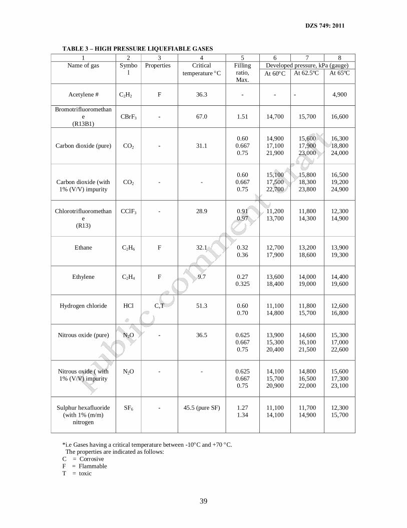
DZS 749: 2011
39
TABLE 3 – HIGH PRESSURE LIQUEFIABLE GASES 1 2 3 4 5 6 7 8
Name of gas Symbol
Properties† Critical temperature °C
Filling ratio, Max.
Developed pressure, kPa (gauge) At 60°C At 62.5ºC At 65ºC
Acetylene #
C2H2
F
36.3
-
-
-
4,900
Bromotrifluoromethane
(R13B1)
CBrF3
-
67.0
1.51
14,700
15,700
16,600
Carbon dioxide (pure)
CO2
-
31.1
0.60 0.667 0.75
14,900 17,100 21,900
15,600 17,900 23,000
16,300 18,800 24,000
Carbon dioxide (with 1% (V/V) impurity
CO2
-
-
0.60 0.667 0.75
15,100 17,500 22,700
15,800 18,300 23,800
16,500 19,200 24,900
Chlorotrifluoromethane
(R13)
CClF3
-
28.9
0.91 0.97
11,200 13,700
11,800 14,300
12,300 14,900
Ethane
C2H6
F
32.1
0.32 0.36
12,700 17,900
13,200 18,600
13,900 19,300
Ethylene
C2H4
F
9.7
0.27 0.325
13,600 18,400
14,000 19,000
14,400 19,600
Hydrogen chloride
HCl
C,T
51.3
0.60 0.70
11,100 14,800
11,800 15,700
12,600 16,800
Nitrous oxide (pure)
N2O
-
36.5
0.625 0.667 0.75
13,900 15,300 20,400
14,600 16,100 21,500
15,300 17,000 22,600
Nitrous oxide ( with 1% (V/V) impurity
N2O
-
-
0.625 0.667 0.75
14,100 15,700 20,900
14,800 16,500 22,000
15,600 17,300 23,100
Sulphur hexafluoride
(with 1% (m/m) nitrogen
SF6
-
45.5 (pure SF)
1.27 1.34
11,100 14,100
11,700 14,900
12,300 15,700
*i.e Gases having a critical temperature between -10°C and +70 °C. †The properties are indicated as follows: C = Corrosive F = Flammable T = toxic

DZS 749: 2011
40
#Acetylene is not a liquefiable gas but dissolved under pressure in acetone. Because the porous filling in acetylene cylinders prevents conventional internal inspections and because the cylinders are subjected to very severe handling in service, the developed pressure of the gas at reference temperature (4,900 kPa at 65°C) is considered inadequate for design purposes, and minimum wall thicknesses shall be based on a hydrostatic test pressure of at least 6,200kPa.
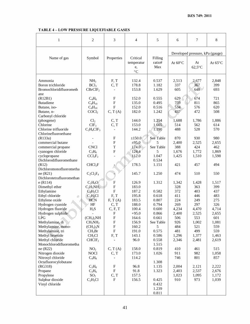
DZS 749: 2011
41
TABLE 4 – LOW PRESSURE LIQUEFIABLE GASES
1
2
3 4
5
6
7
8
Developed pressure, kPa (gauge)
Name of gas Symbol Properties†
Critical temperatur
e, °C
Filling ratio# Max
At 60°C
At
62,5°C
At 65°C
Ammonia Boron trichloride Bromochloridifluoromethane (R12B1) Butadiene Butane, iso- Butane, n- Carbonyl chloride (phosgene) Chlorine Chlorine trifluoride Chlorinefluoroethane (R133a) commercial butane commercial propane cyanogen chloride cyclopropane Dichlorodifluoromethane (R12) Dichloromonofluoromethane (R21) Dichlorotetrafluoromethane (R114) Dimethyl ether Ethylamine Ethyl chloride Ethylene oxide Hydrogen cyanide Hydrogen fluoride Hydrogen sulphide LPG Methylamine, di Methylamine, mono-Methylamine, tri Methyl bromide Methyl chloride Monochlorodifluoromethane (R22) Nitrogen dioxide Nitrosyl chloride Octafluorocylobutane (RG318) Propane Propylene Sulphur dioxide Vinyl chloride
NH3 BCl3
CBrClF2
C4H6 C4H10 C4H10 COCl2
Cl2
ClF3 C2H4ClF3
- -
CNCl C3H6
CCl2F2
CHCl2F
C2Cl2F4
C2H6O C2H5NH2 C2H5Cl C2H5Cl HCN HF H2S
- (CH3)2NH CH3NH2 (CH3)3N CH3Br CH3Cl
CHClF2
NO2 NOCl C4H8
C3H8 C3H6 SO2
C2H3Cl
F, T C, T
-
F F F
C, T (A)
C, T C, T
-
F F T F - - -
F F F
F, T F, T (A)
C, T C, F, T
F F F F F
F, T -
C, T (A) C, T
-
F F
C, T F
132.4 178.8 153.8
152.0 135.0 152.0 182.0
144.0 153.0 144.2
±150.0 ±95.0 174.0 124.4 112.0
178.5
145.7
126.9 183.0 187.2 195.8 183.5 188.0 100.4 +95.0 164.6 156.9 160.2 191.0 143.1 96.0
158.0 173.0 114.2
96.8 91.8
157.5 156.5
0.537 1.182 1.629
0.555 0.495 0.516 1.242
1.254 1.665 1.190
See Table
5 See Table
5 1.047 0.534 1.151
1.250
1.312
0.582 0.618 0.807 0.794 0.600 0.866 0.661
See Table 5
0.575 0.586 0.558 1.515 0.819 1.026
1.308 1.135 1.323
0.425 0.432 1.239 0.811
2,513 337 605
629 759 534 437
1,688 514 488
870
2,400 388
1,676 1,425
421
474
1,342 328 372 411 224 269
4,234 2,400 506 926 484 481
1,296 2,346
410 911 746
2,004 2,403 1,023 910
2,677 367 648
674 811 576 472
1,786 562 528
930
2,525 424
1,772 1,510
457
510
1,428 363 403 446 249 297
4,470 2,525 553
1,002 521 499
1,377 2,481
461 982 801
2,121 2,537 1,095 973
2,848 399 693
721 865 620 508
1,886 614 570
980
2,655 462
1,869 1,598
494
550
1,517 399 437 483 275 326
4,714 2,655 601
1,081 559 559
1,463 2,619
515
1,058 857
2,222 2,676 1,172 1,039

DZS 749: 2011
42
*i.e gas having a critical temperature above 70°C †The properties are indicated as follows: C = Corrosive, F = flammable, T = toxic and T(A) classified as Class A Poison # based on the necessity for the container to be not more than 97% liquid full if the contents are all heated to a temperature of 55°C

DZS 749: 2011
43
TABLE 5 – FILLING RATIOS FOR HYDROCARBON GAS MIXTURES
1 2 Liquid density at 20°C, g/ml* Filling ratios†, max.
0.495-0.499 9 0.500-0.504 9 0.505-0.509 9
0.510-0.514 9 0.515-0.519 9 0.520-0.524 9
0.525-0.529 9 0.530-0.534 9 0.535-0.539 9
0.540-0.544 9 0.545-0.549 9 0.550-0.554 9
0.555-0.559 9 0.560-0.564 9 0.565-0.569 9
0.570-0.574 9 0.575-0.579 9 0.580-0.584 9
0.585-0.589 9 0.590-0.594 9 0.595-0.599 9 0.600-0.604 9
0.421 0.427 0.431
0.439 0.445 0.450
0.457 0.463 0.469
0.475 0.480 0.487
0.493 0.499 0.504
0.510 0.516 0.522
0.528 0.534 0.540 0.546
*If the density of a mixture of hydrocarbon gases is not known, the density at 20°C shall be determined by IP method 432/2000. † Use 0.425 for LPG.

DZS 749: 2011
44
TABLE 6 – FREQUENCY OF INSPECTIONS AND TESTS
1 2 3
Contents of container Frequency
Internal inspection Hydrostatic test Non-corrosive* gas (other than acetylene or air for breathing a) At developed pressure not
exceeding 3 500 kPa: 1) Cylinder+ 2) Portable tank+ b) At a developed pressure
exceeding 3 500 kPa: 1) Cylinder 2) Portable tank
Every 10 years Every 10 years Every 10 years Every 10 years
No test unless there is evidence of abnormal corrosion or damage Whenever an internal inspection is done Every 10 years Every 10 years
Acetylene
Every 2 years or after 1 year and then every 7 years, as relevant (see 5.3.3 (b)
Whenever the porous filling is removed
Corrosive* gas a) Cylinder b) Portable tank
Every 2 years Every 2 years
Every 4 years Every 4 years
Respirable gas for breathing, in special lightweight cylinders (see 3.5) a) Cylinder for underwater use b) Cylinder for surface use
Every year Every 2 years
Every 4 years Every 4 years
* Corrosion gases are indicated in column 3 of Tables 2A, 3 and 4. +LPG containers are exempted from these requirements

DZS 749: 2011
45
TABLE 7 – CLASS OF CONTAINER FOR SPECIFIC GASES
1 2 Name of gas Container class number, max
Acetylene Air Ammonia Argon Boron trichloride Boron trifluoride Bromochlorodifluoromethane (R12B1) Bromotrifluoromethane (R13B1) Butadiene Butane, iso- Butane, n- Carbon dioxide Carbon monoxide Chlorine Chlorine trifluoride Chlorotrifluoroethane (R133a) Chlorotrifluoroethane (R13) Coal gas Cyanagen chloride Cycloprane Dishlorodifluoromethane (R12) Dichloromonofluoromethane (R21) Dichlorotetrafluoromethane (R114) Dimethyl ether Ethane Ethylamine, mono- Ethyl chloride Ethylene Ethylene oxide Fluorine Helium Hydrogen Hydrogen Chloride Hydrogen cyanide Hydrogen fluoride Hydrogen sulphide LPG Methane Methylamine, di- Methylamine, mono- Methylamine, tri- Methyl bromide Methyl chloride Monochlorodifluoromethane (R22) Neon Nitrogen Nitrogen dioxide Nitrosyl chloride Nitrous oxide Octfluorocyclobutane (RC318) Oxygen Phosgene Propane Propylene Sulphur dioxide Sulphur haxafluoride
3 3 3 3 2 1 3 1 3 3 3 1 1 2 2 3 2 1 2 3 3 3 3 3 1 3 3 1 3 1 3 2 1 1 3 3 3 3 3 3 3 3 3 3 3 3 1 2 1 3 3 1 3 3 3 1

DZS 749: 2011
46
Vinyl chloride
3
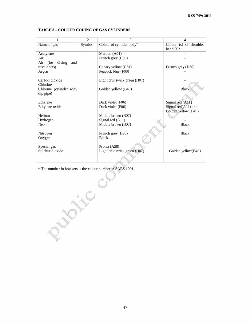
DZS 749: 2011
47
TABLE 8 – COLOUR CODING OF GAS CYLINDERS
1 2 3 4 Name of gas Symbol Colour of cylinder body* Colour (s) of shoulder
band (s)* Acetylene Air Air (for diving and rescue sets) Argon Carbon dioxide Chlorine Chlorine (cylinder with dip pipe) Ethylene Ethylene oxide Helium Hydrogen Neon Nitrogen Oxygen Special gas Sulphur dioxide
Maroon (A01) French grey (H30) Canary yellow (C61) Peacock blue (F08) Light brunswick green (H07) Golden yellow (B49) Dark violet (F06) Dark violet (F06) Middle brown (B07) Signal red (A11) Middle brown (B07) French grey (H30) Black Protea (A58) Light brunswick green (H07)
- -
French grey (H30) - - -
Black
Signal red (A11) Signal red(A11) and Golden yellow (B49)
- -
Black
Black - -
Golden yellow(B49)
* The number in brackets is the colour number in SABS 1091.

DZS 749: 2011
48
TABLE 9 – IMPURITIES IN COMPRESSED AIR FOR BREATHING
1 2 3 4 Impurity Chemical
symbol Limit* Max.
Test method
Carbon monoxide Carbon dioxide Total volatile hydrocarbons (as CH) Water a) At a charging pressure not
exceeding 20 Mpa b) At a charging pressure greater than 20
Mpa but not exceeding 30 Mpa Solid particles (dust, foreign matter, etc.) larger than 5,0 Hydrogen sulphide
10cm³/m³ 500 cm³/m³ 1.0mg/m³ 50mg/m³ 35mg 0.5 mg/m³ 10 cm/m³
+ # ξ
π
** ++
*At or corrected to a temperature of 20°C and a pressure of 101.3 kPa and, except in the case of water content, calculated on a moisture-free basis. +Use the test procedure for “Limit tests for carbon monoxide in medicinal gases” in the current European Pharmacopoeia, adjusted for testing 10 cm³/m³ of carbon monoxide. #Use the test procedure for carbon dioxide in oxygen” in the current European Pharmacopoeia, adjusted for testing 500cm³/m³ of carbon dioxide. πDew point measurement with the use of commercially available dew-point meters. **Pass compressed air from the inverted test cylinder at a rate of 30dm³/min for 5 min. through a synthetic membrane (e.g. vinyl) filter with a nominal pore size of 5 and that has been dried (at 60+ 1º C) the membrane filter in an oven, cool in a desiccator and determine the mass of material, if any collected. At the same time examine the surface of the filter for discoloration and physical particulate such as dust, dirt and metallic and other particles. ++ Use the tentative method of analysis for hydrogen sulphide content of the atmosphere” (No. 42402-01-70T) of the Intersociety Committee, published in Methods of air sampling and analysis by the American Public Health Association, 1015 Eighteenth Street, N.W., Washington D.C., USA.
APPENDIX A. RE-RATING: EXAMPLE OF THE CALCULATION OF THE EQUIVALENT PRESSURE AND THE Z FACTOR FOR A WELDED CONTAINER ALREADY IN USE
(Informative) a) Specification: SANS 219 b) Design pressure = 300 lb/sq in c) Hydrostatic test pressure = 600 lb/sq in d) Minimum wall thickness t = 0,122 in e) Outside diameter of container = 14,858 in f) Minimum specified yield stress of steel Y = 45,000 lb/sq in g) Minimum specified tensile strength of steel T = 65,000 lb/sq in h) Weld factor e = 0,90
i) 692.06545
==TY
, so actual value of Y may be used
(See note (2) TO 10.3.3 (a) Equivalent pressure based on data for cylindrical wall:
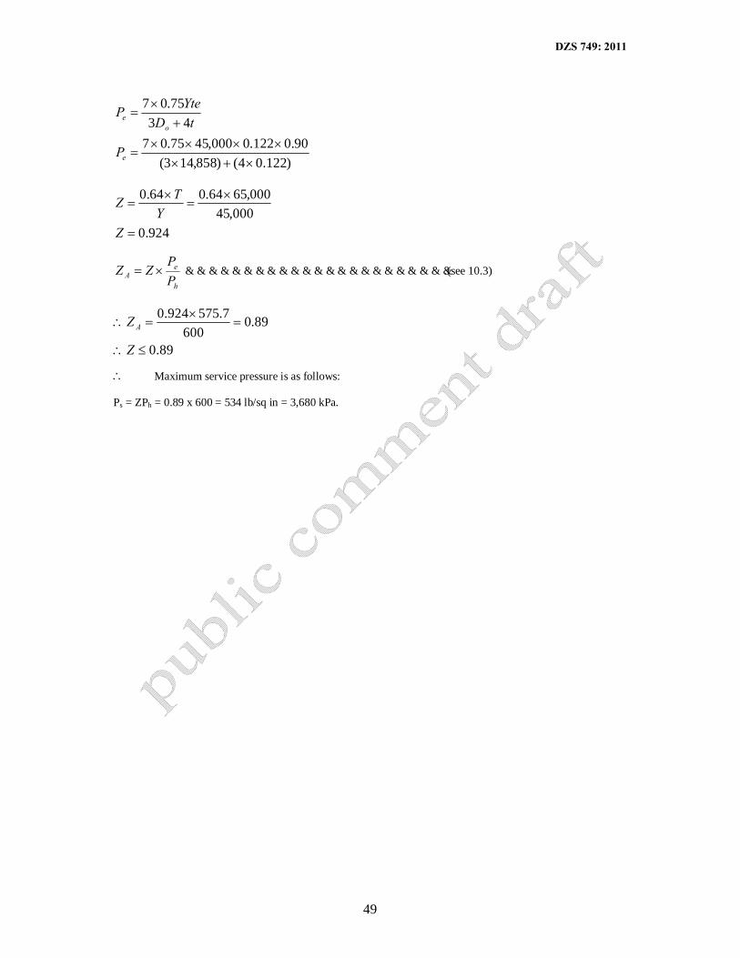
DZS 749: 2011
49
)122.04()858,143(90.0122.0000,4575.07
4375.07
×+×××××
=
+×
=
e
oe
P
tDYteP
924.0000,45
000,6564.064.0
=
×=
×=
ZY
TZ
h
eA P
PZZ ×= …………………………………………………………….(see 10.3)
89.0
89.0600
7.575924.0
≤∴
=×
=∴
Z
Z A
∴ Maximum service pressure is as follows: Ps = ZPh = 0.89 x 600 = 534 lb/sq in = 3,680 kPa.

DZS 749: 2011
50
APPENDIX B. EXTERNAL AND INTERNAL EXAMINATION: COMMON DEFECTS AND CRITERIA FOR REJECTION B-1 Tables B-1 and B-2 give descriptions of common defects that may be found on inspection of containers,
and the criteria for rejection of containers having such defects (see 6.3.2)
NOTE: When the rejection criteria given in Tables B-1 and B2 are being applied, the conditions of use of the container, the severity of the defect and the safety factors in the design shall be taken into consideration.
TABLE B-1 – DEFECTS OTHER THAN CORROSION DEFECTS
1 2 3 Defect Description Criteria for rejection Bulge Visible swelling of the
container All containers with such a defect
Dent A depression in the container that has neither penetrated nor removed metal
Class 1 containers: When the depth of any dent exceeds 2mm or when the width of any dent is less than 30 times its depth at any point. Class 2 and 3 containers: When a dent across a weld exceeds 6 mm in depth or when the width of any dent is less than four times its depth at any point. On small diameter containers these general limits may have to be adjusted. Consideration of appearance also plays a part in the evaluation of dents, especially in the case of small containers.
Cut or gouge A sharp impressed where metal has been removed or redistributed
When the length of any cut or gouge exceeds 75 mm or when the depth exceeds 5% of the wall thickness.
Crack A split or rift in the metal All containers with such a defect Lamination Layerings of the material
within the container wall, sometimes showing as a dis-continuity, crack or bulge at the surface (see fig. C-1)
All containers with such a defect.
Fire damage Excessive general or localised heating of a container usually indicated by a) removal of paint by
burning, b) burning or sintering of
metal, c) burning of container, d) distortion of container, e) melting or metallic
valve parts
All containers with such a defect. NOTE: If paint is only superficially charred, a container may be accepted.
Plug or neck insert
Additional metal inserts fitted in the container neck or wall
Any container that has had a plug or neck insert fitted unless it can be ascertained that the plug or neck insert is part of the approved design of the container.
Stamping Marking by means of a metal punch
Any container with stamping on the parallel section. When stamping is illegible, inadequate or incorrect NOTE: When it can be clearly established from records or otherwise that the container complies fully with the requirements of the appropriate manufacturing standard, an altered marking may be accepted and illegible or inadequate marking may be
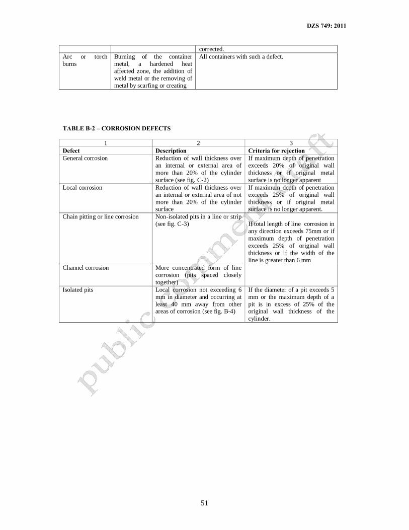
DZS 749: 2011
51
corrected. Arc or torch burns
Burning of the container metal, a hardened heat affected zone, the addition of weld metal or the removing of metal by scarfing or creating
All containers with such a defect.
TABLE B-2 – CORROSION DEFECTS
1 2 3 Defect Description Criteria for rejection General corrosion Reduction of wall thickness over
an internal or external area of more than 20% of the cylinder surface (see fig. C-2)
If maximum depth of penetration exceeds 20% of original wall thickness or if original metal surface is no longer apparent
Local corrosion Reduction of wall thickness over an internal or external area of not more than 20% of the cylinder surface
If maximum depth of penetration exceeds 25% of original wall thickness or if original metal surface is no longer apparent.
Chain pitting or line corrosion Non-isolated pits in a line or strip (see fig. C-3)
If total length of line corrosion in any direction exceeds 75mm or if maximum depth of penetration exceeds 25% of original wall thickness or if the width of the line is greater than 6 mm
Channel corrosion More concentrated form of line corrosion (pits spaced closely together)
Isolated pits Local corrosion not exceeding 6 mm in diameter and occurring at least 40 mm away from other areas of corrosion (see fig. B-4)
If the diameter of a pit exceeds 5 mm or the maximum depth of a pit is in excess of 25% of the original wall thickness of the cylinder.

DZS 749: 2011
52
APPENDIX C: RECOMMENDED FIELD TEST METHODS FOR THE DETERMINATION OF IMPURTIES IN COMPRESSED AIR FOR BREATHING
C-1 OXYGEN. Determine the oxygen content by Orsat volumetric absorption, paramagnetism or by using
an oxygen detection tube.
C-2 CARBON MONOXIDE. Use a carbon monoxide detector tube.
C-3 TOTAL VOLATILE HYDROCARBONS a) Preferably use a hydrocarbon (oil) detector tube. However, a rough check can be made by
inverting the test cylinder for some time, cracking open the cylinder valve and the smelling the escaping air, noting the presence of any smell or taste, and of discoloration when the compressed air is passed gently through a filter paper or a wad of tissue. A pressure reducing valve and a flow meter should be fitted to the test cylinder or compressor to give a flow rate proportional to the take-off requirements for facial breathing apparatus. The average limit of oil that can be smelled is approximately 0.3 mg/m3.
b) An alternative field test that can be carried out for water, oil and particulate matter is to invert the
gas cylinder for at least 5 min, open the valve slightly an allow air to flow into a clean glass container. Oil, water and particulate matter, if present, can be observed on the glass.
C-4 WATER. Use a water-vapour detector tube (see also D-3 (b).)
NOTE: It is essential to remember that the amount of water present in the air emerging from a cylinder increases as the pressure of the air in the cylinder decreases, and that at high rates of withdrawal the resulting drop in temperature may cause water or ice or both to obstruct valves and pressure-reducers.
C-5 SOLID PARTICLES. A rough check for cleanliness can be made by cracking open the valve of an
inverted test cylinder and passing a stream of the air gently through a filter paper or a wad of tissue. (see also D-3(b).)
C-6 HYDROGEN SULPHIDE. Use a hydrogen sulphide detector tube.
WARNING: In any test involving the use of detector tubes, the tubes used must be those supplied or recommended by the manufacturer of the detector kit, as the sampling pumps and tubes made by different manufacturers are not interchangeable.

DZS 749: 2011
53
Appendix D (normative)
Placement of cylinders
Figure D.1 — Correct and incorrect placement of cylinders
Figure D.2 — Directional arrows on cylinders