your pump solution oil and gas industry · oil and gas industry 4 oil and gas industry 5 this...
TRANSCRIPT

YOUR PUMP SOLUTION OIL AND GAS INDUSTRY

2 3OIL AND GAS INDUSTRYOIL AND GAS INDUSTRY
Our global network of oil and gas application specialists focuses on delivering our highly engineered products to you, wherever you are in the field.
The first SEEPEX progressive cavity pump was built in 1972 in Bottrop, Germany. Today, nearly 400 of the 800 worldwide employees work in Bottrop on the development, manufacturing and distribution of pumping solutions for oil and gas production, the environment and many other industries. We have state- of-the-art manufacturing facilities and warehouses in Europe, Asia and North America and distributors in every major country.
Consultation, development, project management and support throughout the entire pump life cycle form the basis of our application expertise. Using our modular pump system we can design a pump tailor-made for each application. This ensures lower energy consumption, reduced maintenance costs, increased operational safety, better utilization of capacity and higher productivity and profits for our clients.
OUR PUMPS CONFORM IN GENERAL TO THE FOLLOWING STANDARDS:
y API 676 rotary positive displacement pumps
y API 682 mechanical seals
y NORSOK M-650
y NACE MR-01-75
y ATEX Directive 94 / 9 / EC
STATE-OF-THE-ART TECHNOLOGY.
The oil and gas industry places some of the toughest demands on its equipment and suppliers. As an established global supplier of products and services for fluid handling and processing, we know what is required to deliver pumping solutions which make a difference.
Even a unique product has to fit within global standards and customers' engineering specifications. Our engineering and project management teams are structured to handle every technical requirement.
We are not only experts in the technical design and manufacture of progressive cavity pumps. Our engineers design, integrate and package fluid handling solutions, turning designs and drawings into reality.
y Research
y Modeling
y Pump selection
y Mechanical seals and systems
y Drive systems
y Instrumentation
y Piping
y Skids
y Control
y Testing
y Third party verification
One of SEEPEX's unique products, the BNA range, is designed to fulfill the exacting requirements of the Oil & Gas Industry and to meet American Petroleum Institute (API) standards.
BNA range pumps have rugged, heavy-duty castings in accordance with API 676 3rd Edition and casing parts made of super duplex stainless steel. Additionally, SEEPEX offers fully API 682 compliant mechanical seals with optimized seal plans. ASTM materials, full traceability and compliance with NACE MR0175 are standard features. The pump can also be designed for gas hazardous areas.
ENGINEERED SOLUTIONS.
KEY FACTS – BNA RANGE y API compliant 676 and 682 y Standardized pump components
FIGURES – BNA RANGE y Conveying capacity:
0.3–110 m3/h (1.32–484 USGPM) y Working pressure (MAWP):
up to 24 bar (350 psi) y Casing pressure (MACP):
up to 50 bar (725 psi)

OIL AND GAS INDUSTRY 54OIL AND GAS INDUSTRY
This typical flow chart gives an overview of the processes and applications SEEPEX pumps are used for in the Oil and Gas industry.
UPSTREAMEXPLORATION
UPSTREAMPRODUCTION
DOWNSTREAM
OIL AND GAS APPLICATIONS.
OPEN / CLOSED DRAINS AND KNOCKOUT DRUM DRAINS
REJECT OIL
LACT / OIL TRANSFER
POLYMER DOSING
MULTIPHASE PUMPING
MEG / TEG CATALYST SLURRY
SEWAGE MACERATION AND PUMPING
GREY WATER
PRODUCED FLUID PUMPING
CAISSON EMPTYING
OPEN / CLOSED DRAINS AND KNOCKOUT DRUM DRAINS
CATALYST INJECTION
POLYMER DOSING
REJECT OIL
MEG / TEG
CONDENSATE
WASTE WATER
DRILLING MUD TRANSFER
CUTTINGS TRANSFER
SEWAGE REMOVAL AND TREATMENT
PRODUCED WATER TREATMENT
FRACKING WATER
FRACKING CHEMICALS PRODUCTION
LOW SHEARGentle low shear pumping action. Oil and water mixtures must be transported with the least damage to the oil droplet size to minimize risk of creating emulsions that are hard to separate.
The Society of Petroleum Engineers (SPE) paper 18204 confirm that progressive cavity pumps are the best pump technology for oil / water separation.
SELF PRIMING AND NO GAS LOCKINGExcellent self-priming characteristics and suction lift capabilities, even on gaseous liquids, up to 9 m (29.5 ft.).
HANDLING OF MULTIPHASE PRODUCTSOil, water and gas are transported reliably by our uniquely configured pumps with control systems to deal with variable flow requirements. Our pumps can be configured to handle up to a 99% gas content.
SOLIDS HANDLINGOur pumps handle products with entrained solids. Drill cuttings and sand, for example, are handled with low internal velocities.
LOW NPSH REQUIREMENTSThe NPSH requirement of our pumps is as low as 0.3 m (0.98 ft.). This is ideal for liquids with elevated temperatures and high vapor pressures.
VISCOSITY IS NOT A LIMITATIONFrom low viscosity condensates to heavily dewatered oily sludge cake, our pumps never give up. With open hopper designs non-flowable products are moved into the rotor / stator pumping elements.
STABLE AND VARIABLE FLOWOur pumps deliver accurate metered flow with every revolution of the rotor. Flow rate variation is minimal even across broad pressure ranges. Flow rates are directly proportional to pump speed.
MINIMAL PULSATIONThe flow rate has minimal pulsation, so there is no need for pulsation dampeners.
VERSATILEIntegration of a SEEPEX pump is easy. They can be installed horizontally, vertically, in a can or fully submerged, to fit the space available. Pump flow is reversible depending upon the process requirements.
HIGH PRESSURESSEEPEX pumps are unique because of our special universal joint construction. We can easily handle suction pressures up to 150 bar (2180 psi) with both our pin and cardan-type universal joints.
SPECIAL PUMP CHARACTERISTICS.
Our technology offers reliable in-service performance.We take care to understand your application needs to ensure optimum pump performance. Appropriate equipment integration in complex systems is essential to ensure success.

76
BACKGROUNDDrilling mud is used for lubrication of the drill bit, to control subsurface pressures, to stabilize the well-bore and to carry the cuttings to the surface. As the drill bit grinds downwards rock cuttings become entrained in the mud flow and are carried to the surface.
TASKTo circulate drilling mud the solids must first be removed. The mixture of mud and cuttings is passed through vibrating screens before being processed in cuttings dryers, hydrocyclones and centrifuges.
For safety reasons cuttings are required to be transported in a closed system as opposed to open conveyors.
SOLUTIONOur pumps are utilized in many steps within drilling waste management. T open hopper pumps are integrated into cuttings handling systems to handle heavy cuttings and have a smaller footprint compared to pneumatic systems.
The variable flow rate, which has minimal pulsation and is directly proportional to rotational speed ensures optimum feeding of separation and processing equipment without the need for flow meters, which are prone to clogging.
SEEPEX pumps fitted with Smart Conveying Technology offer ease of maintenance, longer stator life and a smaller footprint. Replacement of rotor and stator can be carried out without removing pipework, saving installation space.
BENEFITS
y Handling a wide variety of drilling mud with varying densities and solids content
y Variable flow rate achieved by simple speed control
y Shaft speed can be used to calculate forward feed rates
y SCT design enables ease of maintenance and improved uptime
y Pump installation flexibility provides compact footprint
y Cuttings pump provides an enclosed and safe system
DRILLING WASTE MANAGEMENTDRILLING WASTE MANAGEMENT
DRILLING WASTE MANAGEMENT.
FLOW CHART BASED ON
DRILLING WASTE MANAGEMENT
main fl ow inshale shaker cuttings dryer
dryer effl uent pit
centrifuge pit
mud pits
desalter pit
degaser pit
fl occulant metering
centrifuge
centrate tank
RANGE
BNdryer effl uent pump
RANGE
BNcentrate pump
RANGE
BNcutting fl ush pump
RANGE
BNcentrifugefeed pump
RANGE
BNmud pit cleaning pump
RANGE
MD
RANGE
BTVE / BTHEcuttings pump
DRILLING WASTE MANAGEMENT FLOW CHART
APPLICATIONS1. BTVE / BTHE range pumps with
open hopper and auger feed screw located under shale shaker transport cuttings for feeding into cuttings dryer
2. BN range pumps fitted with SCT transport drilling mud from storage tanks into centrifuges / hydrocyclones
3. D pumps for flocculant metering to assist the separation process
4. BN range pumps for mud pit cleaning
CONVEYED PRODUCT y Heavy cuttings
KEY SPECIFICATIONS
ACCURATE VARIABLE FLOW
EASE OF MAINTENANCE

9PRODUCED WATER TREATMENTPRODUCED WATER TREATMENT 8
BACKGROUNDThe effective separation of oil and water is a vital part of any oil and gas production facility. The preservation of oil droplet size and prevention of emulsion formation is crucial to the effective treatment of oily water.
TASKFeeding of oily water separation equipment, either gravimetric or dynamic, is optimized by low shear pumping equipment. The slow running speeds and gentle action of our pumps eliminates problems caused by emulsion formation.
SOLUTIONFeeding the oil / water mixtures to the separator using a SEEPEX pump from product group N is a ‘state of the art’ solution for maximizing the overall efficiency of the system. No demulsifying chemicals need to be added, so operating costs are substantially reduced. SEEPEX even wall stator technology reduces internal slippage and shear and offers a compact design where space is at a premium.
Flow rates can be regulated via simple speed control which eliminates the need for control valves and spill back lines (as used with centrifugal pumps). The removal of these valves further reduces points of shear in the process system. BE range pumps provide a flexible solution in restricted space and when fitted in a ‘can' optimize the NPSH available and the process conditions.
BENEFITS
y Compact design with even wall stator saves space
y Flexible installation and use of BE in ‘can’ design provides compact footprint
y Minimal shear on oil droplets prevents emulsion formation
y Variable flow rate is controlled via simple speed adjustment to optimize efficiency of separation systems
y Pumps can operate with low NPSHr 0.3 m (0.98 ft.) eliminating the need for a separate booster pump
y Eliminates the need for adding chemicals providing substantial cost savings
PRODUCED WATER TREATMENT.
FLOW CHART BASED ON
PRODUCED WATER TREATMENT
producedwater
oily water
water
hazardous drains
water
oil
oil
RANGE
BNknock out drum pump
RANGE
BE
RANGE
BNcentrifuge / hydrocyclone feed pump
RANGE
BNopen drain pump
RANGE
BNreject oil pump
RANGE
BNclosed drain pump
RANGE
BEcanned pump
RANGE
BNreject oil pump
slop oil tank
separator
centrifuge
hydrocyclone
closed drain tank
knock out drum
PRODUCED WATER TREATMENT FLOW CHART
APPLICATIONS1. BE range pumps lift oil from the
slop oil tank to the separator2. BN / BE range pumps transfer
product from the knock out drum to the separator
3. BN / BE range pumps transfer product from open and closed drains to the separator tank
4. BN / NS / N range pumps with even walled stator technology transport produced water to hydrocyclones
5. BN / NS / N range pumps transport reject oil back to the upstream separators or water to induced gas flotation (IGF) units
CONVEYED PRODUCT y Oil/water suspension
KEY SPECIFICATIONS
LOW SHEAR OPERATION
COMPACT DESIGN
LEASED ASSET CUSTODY TRANSFERHYDRAULIC FRACTURING 1110
BACKGROUNDThe use of hydraulic fracturing, or fracking, has made monumental changes in the exploration and production of oil / gas. Fracking has made it possible to economically extract millions of barrels of oil and gas from certain types of rock formations that otherwise would go undeveloped.
TASKThe fracking fluid typically contains sand or other proppants, suspended with the aid of gelling agents, all mixed in the correct proportions. It is injected under high pressure into a well to create cracks in rock formations. The proppants fill the fractures, holding them open, providing the natural gas and petroleum with a pathway out of the formation, enabling easier extraction of products. The recovered flowback and produced water contains chemical compounds and suspended solids that need to be removed and treated before the water can be re-used or disposed of.
SOLUTIONThe ability of SEEPEX pumps to handle viscous products and suspended solids, together with a low shear action to preserve the emulsion’s physical properties, makes them ideal for metering and blending the components of the fracking liquid.
For recovered water treatment SEEPEX pumps can handle liquids with suspended solids and variable viscosities, while applying minimal shear to pipelines where the pressures can vary more than 20 bar (290 psi).
BENEFITS
y Multiphase liquids are transferred without emulsification
y Non-pulsating metered flow at varying discharge pressures
y Low and high API oils can be handled
y Suspended solids handled
y Accurate linear flow rate for proportional control of multiple components
BACKGROUNDLeased Asset Custody Transfer (LACT) units play an increasingly important role in developing new oil fields and getting the product to market. Directional drilling allows multiple wells to be drilled from one pad. The oil from several wells, often with multiple owners, is trans-ferred in a common pipeline along with oil from many other wells, which may also have multiple owners. LACT units play a vital role in getting the oil into the pipeline and in determining the correct amount being transferred so the well owners are properly compensated.
TASKDuring custody transfer, accurate measurement of the volume of oil transferred into a tank battery or pipeline is crucial in determining the compensation that the well owner should receive. The meters used are intolerant of pulsating flow.
LACT pumps face some unique challenges. Inlet pressures can be up to 10 bar (145 psi) and discharge pressures can vary more than 20 bar (290 psi) in the space of just a few hours. In some locations fluid viscosities are below API 9 and in others are greater than API 40. Sand may be present in all locations.
SOLUTIONSEEPEX pumps maintain their accuracy over varying pressures, despite changes in product viscosity and the presence of solid particles, making them ideal for this task. Pumps fitted with even wall stators, save space on LACT skids and have lower power requirements.
BENEFITS
y Linear flow rate for accurate measurements
y Pump a wide range of viscosities
y Ability to handle solids
y Resistance to abrasion, low speeds to prevent wear
y Can pump against a varying pressure without affecting the flow rate
y High pressure pumps available
y Minimal pulsation
FRACKING. LACT.
CONVEYED PRODUCT y Fracking fluid components
KEY SPECIFICATIONS
HANDLES LIQUIDS WITH VARIABLE VISCOSITY
HIGH PRESSURE PUMPING
LOW SHEAR OPERATION
HANDLES SUSPENDED SOLIDS
APPLICATIONS y BN / N range pumps to meter,
blend and transfer fracking liquid to the high pressure injection system
y BN / N range pumps with even wall stators to feed separators after oil / fluid extraction
y BN / N range pumps with even wall stators to feed water treatment equipment and transfer sludge
y MD / BN / N range pumps to meter and inject treatment chemicals
CONVEYED PRODUCT y Oil/gas mixture
KEY SPECIFICATIONS
ACCURATE, LINEAR FLOW RATE
VARIABLE VISCOSITY PUMPING
HIGH PRESSURE
APPLICATIONS y BN range, API and high pressure
pumps [up to 48 bar (700 psi) for transfer into oil pipelines]

FLOW CHART BASED ON
MULTIPHASE BOOSTING
RANGE
MD
RANGE
MD
CO RANGE
BNhigh pressure pump
RANGE
BNhigh pressure pump
RANGE
BNhigh pressure transfer pump
RANGE
BNoil transfer
RANGE
BNmultiphase pump
RANGE
BNRANGE
BN
water injection
polymer injection
lubricant dosing
lubricant dosing
oil well gathering station
separationtank
storage tank
reservoir
refi nery
trucks and ships
MULTIPHASE BOOSTING AND CRUDE OIL TRANSFER FLOW CHART
APPLICATIONS1. BN / NS / N range pumps with
even wall stator transport multiphase liquids from oil wells to gathering stations and intermediate storage facilities
2. BN / NS / N range pumps for long distance surface transfer of the separated oil to storage tanks
3. D pumps provide lubrication fluid in controlled doses to the multiphase pump
4. BN / NS / N range pumps with even wall stators for long distance pumping of crude oil from storage tanks to refineries / ships and trucks
5. BN / NS / N high pressure pumps with even wall stators for water and polymer injection for oil recovery
1312 MULTIPHASE BOOSTING AND CRUDE OIL TRANSFERMULTIPHASE BOOSTING AND CRUDE OIL TRANSFER
BACKGROUNDPumping has become an accepted method of multiphase boosting of oil flow from wells, increasing revenue from a well site. The transfer of multiphase liquid from oil wells means that separation can be carried out at the gathering station before transfer to the refinery.
Enhanced oil recovery is a series of processes that have been developed to increase the efficiency of oil extraction from wells, particularly heavy crude oil, or that from mature oil fields.
TASKAsset optimization programs take advantage of multi-phase pumping technology. This allows bottom hole pressures to be reduced and production rates and well yields to increase. To enhance oil recovery high pressure polymer flooding and water injection is used.
SOLUTIONSEEPEX multiphase progressive cavity pumps and control systems provide a highly competitive product range driven by research and development. Package solutions allow for automatic control of the multiphase boosting system enabling pumps to achieve reliable performance in changing and challenging well conditions with gas content of up to 99%. Pump systems are delivered to be tolerant to changing flow requirements and prolonged gas slugging.
SEEPEX high pressure pumps are used for water injection, polymer flooding and crude oil transfer applications.
MULTIPHASE BOOSTING AND CRUDE OIL TRANSFER.
CONVEYED PRODUCT y Multiphase liquid oil y Crude oil y Lubrication fluid
KEY SPECIFICATIONS
HIGH PRESSURE PUMPS
CONTROL SYSTEMS
MULTIPHASE PUMPING
BENEFITS
y Multiphase pumps enable separation at more efficient gathering stations
y Long distance transfer and polymer injection possible with high pressure pumps
y Even wall stators for cooler running temperatures and compact designs
y Minimal pulsation and low shear action minimizes emulsion formation and preserves oil quality
y Booster pumps can handle heavy crude oil with high gas and high solids contents
y Low internal fluid velocities reduces erosion, providing extended pump life and increased reliability
y Reduced release of methane gas into the atmosphere

1514 CATALYTIC REACTIONSMONOETHYLENE GLYCOL
BACKGROUNDMonoethylene glycol (MEG) is used to inhibit the formation of hydrates in pipelines and at wellheads, its recovery is essential to minimize operating and waste disposal costs.
TASKThe gas recovery process is designed for purification, to remove water (condensate) and inorganic salts and to restore the required glycol purity, after which it can be re-used. The separation process is carried out offshore, frequently under low NPSH conditions and typically involves:
y Pre-treatment
y Separation of MEG from impurities
y MEG regeneration or concentration to original purity
y Salt management concentration of monovalent inorganic salts (sodium)
y Divalent salts e.g. calcium, removal and concentration
SOLUTIONThe properties of SEEPEX progressive cavity pumps, specifically the constant flow with minimal pulsation and the ability to handle highly viscous products with entrained solids, make them ideal for several applications in this process.
BENEFITS
y Flow rates can be regulated by simple speed control and are not affected by varying pressures
y SEEPEX pumps can handle solid particles and impurities
y High viscosity products can be handled
y Ability to work under extremely low NPSH conditions
y Flexible installation configurations where space is limited
y Accurate linear dosing for chemical addition
MEG RECLAMATION.
BACKGROUND‘Cracking’ is the term used to describe the breaking of large hydrocarbon molecules into smaller compounds.
Polymerisation is the reverse process of building long chain polymers from the building blocks produced by the cracking process. Catalysts are used in both these processes to reduce temperature and pressure demands and to shape the characteristics of the molecules produced.
TASKMany of the catalysts used are Metallocene powders, which are heavy and very abrasive and have to be injected continuously into the reactor at a very low but constant flow rate, against the high pressure of the reactor.
SOLUTIONThe catalyst is mixed with oil to make a slurry of high viscosity which is then pumped into the reactor by SEEPEX pumps from product groups N and D. This is a critical pump duty since failure results in reactor shutdown or faulty products.
BENEFITS
y Accurate linear flow rate is variable and directly proportional to pump speed
y Wetted parts optimized for wear resistance
y Low pulsation flow, dampeners not required
y Multistage rotor / stator to minimize pressure rise per stage
y Gearbox with backstop to prevent autorotation when pump stops
y Fully automated system integrated into the reactor control loop which monitors pressure, speed and flow
CATALYTIC REACTIONS: CRACKING, POLYMERISATION.
CONVEYED PRODUCT y Monoethylene glycol (MEG)
KEY SPECIFICATIONS
VISCOUS PRODUCTS CONTAINING SOLIDS
LOW NPSH CONDITIONS
APPLICATIONS y BN / N range pumps transport
the salt / MEG slurry to the salt management system
y BT / T range pumps remove mechanically thickened salt slurry from beneath centrifuges
y BN / N range pumps mounted vertically feed wash water to the condensing system
y D dosing pumps add chemicals to control pH and inhibit corrosion
CONVEYED PRODUCT y Catalyst/oil mix
KEY SPECIFICATIONS
HIGH WEAR RESISTANCE
MINIMAL PULSATION FLOW
FULLY AUTOMATED SYSTEMS
APPLICATIONS y BN pumps in special design y D range pumps in special design

SUMP AND CAISSON EMPTYING 16
BACKGROUNDSumps and caissons are used in the oil and gas industry to contain waste from open and closed drains, produced water and slop oil. During operation water or oil drained from the oil platform is channeled into the caisson to prevent environmental impact on the sea around the platform.
TASKThe drained water, which may contain contaminants such as heavy crude oil, solids and chemicals, has to be removed from the narrow confines of the caisson leg and pumped away for treatment before disposal.
SOLUTIONSEEPEX vertical pumps, both fully and semi-submersible designs, lift viscous products and those containing solids from the caisson and transfers them to separation equipment.
The advanced technology of SEEPEX fully submersible progressive cavity pumps incorporates a motor and gearbox installed below the pump body at the bottom of the caisson with the discharge pipe connected to the tank top flange. Segmented discharge pipework gives the flexibility for installation at depths of 30 m (98.4 ft.) or more and the pump drives can be electric, hydraulic or pneumatic, manufactured in duplex or super duplex stainless steel.
Semi-submersible pumps from the BE range have the drive mounted out of the liquid. The length of pump is designed to suit the application conditions.
BENEFITS
y Critical suction conditions can be overcome
y Pumps engineered to specific dimensions
y No internal valves
y Low shear, non-emulsifying pumping action
y Effective pumping solution in a limited space
y Pulsation free, continuous flow independent of discharge pressure
y Handles low to high viscosity products with entrained solids
For transfer of liquids from sumps and caissons to upstream separators, fully submersible pumps can be installed inside a caisson at a depth of 30 m (98.4 ft.). The fully submersible progressive cavity pump is manufactured in super duplex and features an electric motor and gear box.
SUMP AND CAISSON EMPTYING.
FULLY SUBMERSIBLE PUMPS
CONVEYED PRODUCT y Drained water with heavy crude
oil, solids and chemicals
KEY SPECIFICATIONS
FULLY OR SEMI- SUBMERSIBLE PUMPS
INSTALLATION AT DEPTH > 30 M
CONFINED SPACE SOLUTION
APPLICATIONS y BN range pumps submerged with
permanent magnet, pneumatic or hydraulic motor for caisson emptying
y BE range semi-submersible pump for tank and sump emptying
SUMP AND CAISSON EMPTYING 17
FLOATING, PRODUCTION, STORAGE AND OFF-LOADINGNPSH 1918
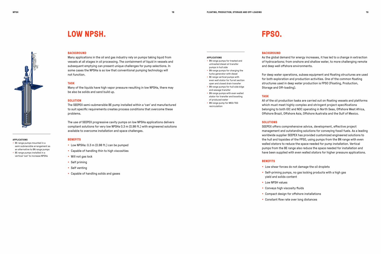
BACKGROUNDMany applications in the oil and gas industry rely on pumps taking liquid from vessels at all stages in oil processing. The containment of liquid in vessels and subsequent emptying can present unique challenges for pump selections. In some cases the NPSHa is so low that conventional pumping technology will not function.
TASKMany of the liquids have high vapor pressure resulting in low NPSHa, there may be also be solids and sand build up.
SOLUTIONThe SEEPEX semi-submersible BE pump installed within a ‘can' and manufactured to suit specific requirements creates process conditions that overcome these problems.
The use of SEEPEX progressive cavity pumps on low NPSHa applications delivers compliant solutions for very low NPSHa 0.3 m (0.98 ft.) with engineered solutions available to overcome installation and space challenges.
BENEFITS
y Low NPSHa: 0.3 m (0.98 ft.) can be pumped
y Capable of handling thin to high viscosities
y Will not gas lock
y Self priming
y Self venting
y Capable of handling solids and gases
LOW NPSH.
BACKGROUNDAs the global demand for energy increases, it has led to a change in extraction of hydrocarbons; from onshore and shallow water, to more challenging remote and deep well offshore environments.
For deep water operations, subsea equipment and floating structures are used for both exploration and production activities. One of the common floating structures used in deep water production is FPSO (Floating, Production, Storage and Off-loading).
TASKAll of the oil production tasks are carried out on floating vessels and platforms which must meet highly complex and stringent project specifications belonging to both IOC and NOC operating in North Seas, Offshore West Africa, Offshore Brazil, Offshore Asia, Offshore Australia and the Gulf of Mexico.
SOLUTIONSSEEPEX offers comprehensive advice, development, effective project management and outstanding solutions for conveying fossil fuels. As a leading worldwide supplier SEEPEX has provided customized engineered solutions to the hull and topsides of the FPSO, using pumps from the BN range with even walled stators to reduce the space needed for pump installation. Vertical pumps from the BE range also reduce the space needed for installation and have been supplied with even walled stators for higher pressure applications.
BENEFITS
y Low shear forces do not damage the oil droplets
y Self-priming pumps, no gas locking products with a high gas yield and solids content
y Low NPSH values
y Conveys high viscosity fluids
y Compact design for offshore installations
y Constant flow rate over long distances
FPSO.
APPLICATIONS y BE range pumps mounted in a
semi submersible arrangement as an alternative to BN range pumps
y BE range pumps installed in a vertical ‘can' to increase NPSHa
APPLICATIONS y BN range pumps for treated and
untreated diesel oil transfer pumps in hull side
y BN range pumps for charging the turbo generator with diesel
y BE range vertical pumps with even wall stator for Turret section open and closed drain transfer
y BN range pumps for hull side bilge and sewage transfer
y BN range pumps with even walled stator for transfer and boosting of produced water
y BN range pump for MEG / TEG recirculation

REFINERY WASTE WATER
BACKGROUNDThe treatment of effluent streams in refining and petrochemical processing plants is a necessary part of the process. Strict environmental legislation and advancing technologies present challenges for plant builders and operators.
TASKOily waste water and slop streams from oil-water (API) separators and skim tanks have to be transferred to treatment equipment. Operations are optimized with a pump that can handle varying and high viscosities and does not clog when exposed to waxy paraffinic oils.
SOLUTIONSEEPEX BN range pumps effectively handle abrasive sludges and slurries. Dosing of corrosion inhibitors and general chemicals is achieved with our MD range pumps. Accurate and repeatable flow rate is achievable that complies with API 675.
Non flowable products like oily sludge cake with dry solids contents of approximately 60% can be transported by our open hopper pumps of product group T.
BENEFITS
y Handling thin to high viscosity liquids with entrained solids
y Low shear
y Low NPSHr 0.3 m (0.98 ft.)
y Horizontal and vertical pump installation possible
y Accurate repeatable linear flow rates
y Flow control through variable speed drives
y Open hopper and auger feed design for high solids cake handling
REFINERY WASTE WATER AND SLUDGE APPLICATIONS.
20
CONVEYED PRODUCT y Oily waste water y Slop oil y Oily sludge cake
KEY SPECIFICATIONS
LOW SHEAR
FLEXIBLE INSTALLATION CONFIGURATION
NON FLOWABLE PRODUCTS PUMPED
APPLICATIONS y BE range pumps transport slop oil
from oil-water (API) separators to further processing
y MD range pumps for accurate chemical metering
y BN range pumps fitted with SCT for separation equipment feeding and transportation of wastewater for further processing
y BTHE / BTEI range pumps transport dewatered oily sludges for onward processing

YOUR PUMP SOLUTIONS AT A GLANCE.
SEEPEX pumps transport thin to highly viscous products with or without solids and low to high temperature products gently and with minimal pulsation. They also feature excellent metering accuracy and can easily pump media such as produced water and chemical additives. All pumps can be engineered to meet API 676 requirements.
Product group N pumps offer a variety of ranges for this industry. BNA range pumps come in a heavy duty design and are fully API 676 compliant. BN range pumps with direct flange-mounted drives can be used in almost all areas of industry to convey thin to high viscosity materials with or without solids. NS / N range pumps feature a drive casing with a free shaft end for universal configuration of drives through flexible couplings or V-belts.
y Conveying capacity: 0.05–500 m3/h (0.132–2,200 USGPM)
y Pressure: up to 96 bar (1400 psi)
BTHE range pumps feature a feed hopper with vertical hopper walls and a ribbon screw rotating centrically and on the edges. This guarantees optimum emptying of the feed hopper and optimized feed of the medium into the conveying elements of the pump. The length of the hopper opening is variable to suit the respective application conditions.
y Conveying capacity: 0.5–130 m3/h (2.2–572 USGPM)
y Pressure: up to 36 bar (525 psi)
BT range pumps have a rectangular inlet hopper with a cylindrical compression zone and auger feed screw. The hopper inlet length is customized according to customer needs. These pumps are used to convey highly viscous products.
y Conveying capacity: 0.1–300 m3/h (0.44–1,320 USGPM)
y Pressure: up to 36 bar (525 psi)
BTVE range pumps feature a sliding compression casing with an enlarged cross section to simplify service. A solid auger feed screw with a long pitch, enlarged diameter and increased blade thickness for durability enables longer operating times.
y Conveying capacity: up to 120 m³/h (530 USGPM)
y Pressure: up to 36 bar (525 psi)
MD range pumps are used for pumping and dosing small quantities. They are especially suited for low pulsation transport of low to highly viscous or adhesive media as well as media containing solids and chemically aggressive media with a high dosing accuracy.
y Conveying capacity: 0.2–1000 l/h (0.053–264 USGPH)
y Pressure: up to 24 bar (350 psi)
BTEI range pumps have a rectangular feed hoper with enlarged compression zone and an auger with enlarged diameter and pitch. The hopper length can be matched to the individual operating conditions.
y Conveying capacity: 0.5–100 m3/h (2.2–440 USGPM)
y Pressure: up to 36 bar (525 psi)
Semi-submersible pumps of the BE range are used to empty tanks, drums, reservoirs and pits when limited space is available or when the danger of cavitation is present.
y Conveying capacity: 30 l/h–300 m3/h (0.132–1,320 USGPM)
y Pressure: up to 12 bar (175 psi)
Can pumps are semi-submersible pumps of the BE range installed in a ‘can’ to improve NPSHa at the pump outlet.
y Conveying capacity: 30 l/h–300 m3/h (0.132–1,320 USGPM)
y Pressure: up to 12 bar (175 psi)
BNA RANGE
MD RANGE
BTHE RANGE
BT RANGE
BTVE RANGE
BTEI RANGE
BE RANGE
CAN PUMP
SOLUTIONS FOR EVERY INDUSTRYSOLUTIONS FOR EVERY INDUSTRY 2322

SEEPEX GmbHwww.seepex.com
BR.O
G.EN
_01.1
8