your formula for success
TRANSCRIPT

Product Catalog
Your Formula for Success

Thread Rolls & Knurls ..............................................................2-14
Ordering Information ........................................................................... 2
Thread Rolling Basics .......................................................................... 3
Thread Roll Styles ..........................................................................4-12
Knurls ............................................................................................. 13
Burnishing Rolls ............................................................................... 14
Thread Rolling Attachments ..................................................15-24
Thread Rolling Attachments ..........................................................16-20
Match Taper ..................................................................................... 21
Radial Infeed Pinch Type .................................................................... 22
NC41 Tangential Attachment .............................................................. 23
Detroit Style Attachments .................................................................. 24
Quick Change Tooling ............................................................25-36
Davenport Style Tool Holders, Slides, Accessories ............37-64
Davenport Style Tool Holders ........................................................38-56
108-109 Shave Tools ......................................................................... 57
111 Shave Tool ................................................................................. 58
Davenport Tool Slides ...................................................................59-60
ER Series End Rolling Attachments ................................................61-63
Bent Shank Taps ............................................................................... 64
Links & Link Blanks .......................................................................... 64
Thread Roll Troubleshooting Guide ......................................65-66
Notes ........................................................................................67-68
www.cjwinter.com
Table of Contents
Call: 1-800-288-ROLL (7655) • Fax: 1-585-429-5095

2 Your Formula for Success
CJWinter manufactures the premier line of thread rolling attachments, thread rolls and specialty dies and tooling for multi-spindle and CNC machines. Our higher quality threads, ease of attachment adjustments, and lower initial cost have been our competitive edge for over 50 years. Our team of dedicated engineers focuses daily on solving every customer’s thread rolling and metal forming challenge resulting in world-renowned customer service.
From CJWinter, you get: • Half a century of leading-edge service to the
machining industry • Individual attention • Superior service • Flexibility ... not just from us, but from our
adjustable, on-the-fly attachments • Meticulous attention to detail • Repeatable reliability, down to the micron • Innovation and quality • Every one of our sales staff is equipped with
intensive hands-on training and experience as an operator. They understand what you need, and are able to customize jobs to meet your exact specifications.
We don't have customers. We have partners.We know the secret to good business; from your smallest order to your largest project, our success depends on your success. We provide: • Innovation that makes your life a lot easier • Tools and attachments that can be up and running in
a snap and adjusted on the go • Instant access to engineers who will work with you
on part design and specifications • Value added to every step of your transaction, from
knowledgeable sales staff up front to after-sale support
• Customization of almost every product, down to the smallest thread roll, built specifically for you, to your specifications, to meet your needs
• Factory spare parts available with all of the quality and longevity you would expect from CJWinter
We Meet Your High-Precision Needs
How to Order Thread RollsWhen placing an order or requesting a quote, please have the following information available: 1. Make and model of thread rolling attachment 2. Style of thread roll (i.e. D-1, DR-1, C-1, etc.) 3. Size and pitch of thread to be rolled, including dimensional
tolerances if other than standard 4. Length of thread on part 5. Material to be rolled 6. Print of part to be rolledNote: 1. Special rolls may require a sample part or more detailed
specifications 2. Some rolls require a special calculation to figure the work
face on the roll. Please refer to page 3 of the catalog or call the factory directly.
Reliable Fast DeliveryNext-Day Delivery! As you know, a damaged thread roll or sudden change in lead time can be detrimental to your production schedule. That’s why we process orders for in stock items several times a day and excel at producing special rolls quickly. We can get you back up and running quickly with our superior products and reliable fast delivery. You can count on it.
Real People or the Internet – It’s Your ChoiceCJWinter maintains a network of highly qualified distributors who are able to work with you to solve problems, answer questions and assist in ordering.Or, if you prefer, log on to our web site www.cjwinter.com for the latest product and technical information.
NOTE: UNlEss OThErwisE sTaTEd, mEasUrEmENTs arE iN dECimal iNChEs.
© 2009 CJWinter. CJWinter is a registered trademark of the Brinkman International Group, Inc. Pages and product photography in this catalog may not be scanned, photocopied or transmitted for reproduction use without the express permission of CJWinter. Hydromat is a registered trademark of Hydromat, Inc. Brown & Sharpe, National Acme and New Britain are registered trademarks of DeVlieg-Bullard Services Group, Davenport is a registered trademark of Davenport Machine, Gildemeister is a registered trademark of Akiengesellshest, Germany Hardinge is a registered trademark of Tornos-Bechler, Wickman is a registered trademark of Wickman Coventry Ltd., Traub is a registered trademark of Traub Drehmaschinem GmbH,
Reed-Rico is a registered trademark of PCC Speciality Products, Inc. Warner & Swasey is a registered trademark of Gidding & Lewis Ltd., Landis is a registered trademark of Teledyne Landis Machine, Green Lee is a registered trademark of Green Lee Brothers Co., Cono-Matic is a registered trademark of Cone Blanchard Corporation, Mitsubishi is a registered trademark of Mitsubishi International Corp., Fette is a registered trademark of LMT Fette Ltd., Salvo is a registered trademark of Salvo Tool & Engineering Co., Schutte is a registered trademark of Alfred H. Schutte Werkzeuqmaschmenfabrik GmbH & Co.
Decimal Equivalents
3/16 = .1875/16 = .3127/16 = .437
1/8 = .125 3/8 = .3755/8 = .6257/8 = .875
1/4 = .2501/2 = .5003/4 = .750
�www.cjwinter.comCall: 1-800-288-ROLL (7655) • Fax: 1-585-429-5095
Thread Roll Basics
This section includes a complete listing of standard thread rolls for each thread roll holder. Although we have outlined general considerations for determining what style of thread roll to use, part configuration ultimately determines which thread roll style will be appropriate.Once a particular style has been selected, the next step is to choose the widest roll width that can be accommodated by the geometry of the part. If you are in doubt as to whether a particular thread roll width will produce the thread length required, refer to the “How To Determine Correct Working Face” portion of this section (below).Although we try to standardize as many thread roll styles as possible, there will still always be applications when a specially designed thread roll is required. Our sales and engineering staff are trained to assist you in determining the style of thread roll that will best suit your needs. Please see the “How To Order Thread Rolls” section on the preceding page to determine the information required.
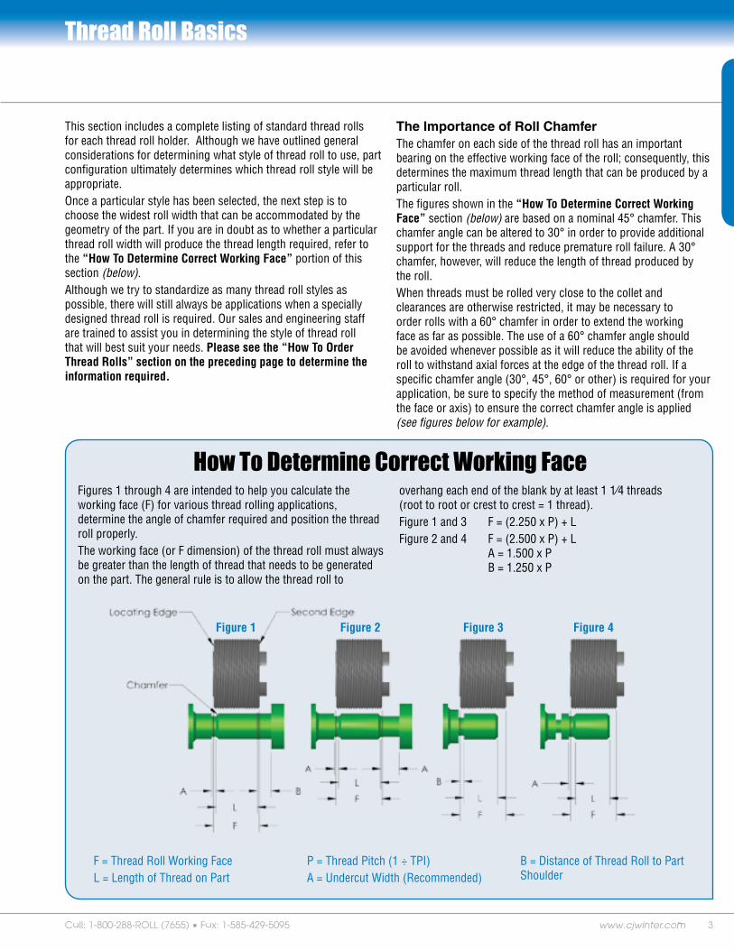
The Importance of Roll ChamferThe chamfer on each side of the thread roll has an important bearing on the effective working face of the roll; consequently, this determines the maximum thread length that can be produced by a particular roll.The figures shown in the “How To Determine Correct Working Face” section (below) are based on a nominal 45° chamfer. This chamfer angle can be altered to 30° in order to provide additional support for the threads and reduce premature roll failure. A 30° chamfer, however, will reduce the length of thread produced by the roll. When threads must be rolled very close to the collet and clearances are otherwise restricted, it may be necessary to order rolls with a 60° chamfer in order to extend the working face as far as possible. The use of a 60° chamfer angle should be avoided whenever possible as it will reduce the ability of the roll to withstand axial forces at the edge of the thread roll. If a specific chamfer angle (30°, 45°, 60° or other) is required for your application, be sure to specify the method of measurement (from the face or axis) to ensure the correct chamfer angle is applied (see figures below for example).
F = Thread Roll Working FaceL = Length of Thread on Part
P = Thread Pitch (1 ÷ TPI)A = Undercut Width (Recommended)
B = Distance of Thread Roll to Part Shoulder
Figures 1 through 4 are intended to help you calculate the working face (F) for various thread rolling applications, determine the angle of chamfer required and position the thread roll properly.The working face (or F dimension) of the thread roll must always be greater than the length of thread that needs to be generated on the part. The general rule is to allow the thread roll to
overhang each end of the blank by at least 1 1⁄4 threads (root to root or crest to crest = 1 thread).Figure 1 and 3 F = (2.250 x P) + LFigure 2 and 4 F = (2.500 x P) + L A = 1.500 x P B = 1.250 x P
How To Determine Correct Working Face
Figure 1 Figure 2 Figure 3 Figure 4

4 Your Formula for Success
Type WC-1 Thread Rolls for Straight Threads
USE WC-1 STYLE WHEN: 1) Rolling on outboard end of work. 2) Standard working face is satisfactory for length of thread
to be rolled. 3) Position of attachment in relation to collet is not important. 4) Sufficient clearance is available on either side of working face.
STANDARD: Working face as listed above.
OPTIONAL: Special bevels, machined breakouts, bronze bushings, left hand threads, multiple leads.
Type WCR-1 Thread Rolls For Straight Threads
USE WCR-1 STYLE WHEN: 1) Length of thread on part permits rolls to be reversed (doubling
production from each pair of rolls).
See instructions for determining correct working face located on page 3.
STANDARD: Double drive slots; working face as listed above.
OPTIONAL: Special bevels, machined breakouts, bronze bushings, left hand threads, multiple leads.
Thread Roll Styles Straight ThreadsUN–American Standard Unified Screw Threads–Classes 1A, 2A, 3A; N–American National Screw Threads–Classes 2 and 3; ISO Metric Screw Threads; NPSM and NPSL American Standard Straight Pipe Threads for Mechanical Joints
WC-1 Standard Workface
Model125-SA134-SA141-SA151-SA160-SA162/163-SA170-SA172/173-SA
Std. W.F.0.5520.6250.8750.8751.5301.2651.5301.265
Model14GA18GA20GA22GA24GA
Std. W.F.0.6250.8441.0001.3751.500
Model76000 (0-375)76100 (6-625)76200 (10-750)76300 (30-1000)76400 (25-1125)
Std. W.F.0.4680.6250.8120.8121.062
Model1421-SA1431-SA1448-SA
Std. W.F.0.6250.6250.625
ModelB-5B-8B-10 (500-G2A)B-13 (750-G2A)B-18 (1000-G2A)B-36
Std. W.F.0.5000.5000.6250.8751.1251.125
ModelCBLBBLDBL
Std. W.F.0.8121.0621.312
Winter Landis Detroit
Davenport
Reed
Salvo
WCR-1 Standard Workface
Model125-SA134-SA141-SA151-SA160-SA162/163-SA170-SA172/173-SA
Std. W.F.0.4800.5000.7500.7501.4171.1351.4171.135
Model14GA18GA20GA22GA24GA
Std. W.F.0.5000.7500.8131.0001.250
Model76000 (0-375)76100 (6-625)76200 (10-750)76300 (30-1000)76400 (25-1125)
Std. W.F.0.3440.5000.6880.6880.938
Model1421-SA1431-SA1448-SA
Std. W.F.0.5000.5000.500
ModelB-5B-8B-10 (500-G2A)B-13 (750-G2A)B-18 (1000-G2A)B-36
Std. W.F.---
0.4370.5000.7501.0001.000
ModelCBLBBLDBL
Std. W.F.0.7500.9371.187
Winter Landis Detroit
Davenport
Reed
Salvo

5www.cjwinter.comCall: 1-800-288-ROLL (7655) • Fax: 1-585-429-5095
Type WC-2 Thread Rolls for Straight ThreadsUSE WC-2 STYLE WHEN: 1) Rolling threads behind a shoulder at cut-off end. 2) Narrow width is required due to part
configuration. 3) Attachment will be positioned as close to collet
as possible.
OPTIONAL: Special bevels, machined breakouts, bronze bushings, double drive slots, left hand threads, multiple leads.
Type WC-3 Thread Rolls for Straight ThreadsUSE WC-3 STYLE WHEN: 1) Rolling threads away from the cut-off end. 2) There is a shoulder between the threaded portion
and the collet. 3) Attachment will be positioned as close to collet
as possible.
OPTIONAL: Special bevels, machined breakouts, bronze bushings, double drive slots, left hand threads, multiple leads.
Type WC-4 Thread Rolls for Straight ThreadsUSE WC-4 STYLE WHEN: 1) It is important to maintain position of attachment
on the cross slide. 2) It is necessary to maintain the position of the
cut-off end of the part relative to the collet.
OPTIONAL: Special bevels, machined breakouts, bronze bushings, double drive slots, left hand threads, multiple leads.
Working face must be specified when ordering WC-2 style.
See instructions for determining correct working face located on page 3.
Working face must be specified when ordering WC-3 style.
See instructions for determining correct working face located on page 3.
Working face must be specified when ordering WC-4 style as well as length of hub opposite the drive slot.
See instructions for determining correct working face located on page 3.
Thread Roll Styles Straight ThreadsUN–American Standard Unified Screw Threads-Classes 1A, 2A, 3A; N–American National Screw Threads–Classes 2 and 3; ISO Metric Screw Threads; NPSM and NPSL American Standard Straight Pipe Threads for Mechanical Joints

6 Your Formula for Success
Type WD-1 Thread Rolls for Straight Threads
USE WD-1 STYLE WHEN: 1) Working face or rolls with standard hubs are not sufficient
for length of thread required.
See instructions for determining correct working face located on page 3.
STANDARD: Recessed drive slot, extended standard ` working face as listed above.
OPTIONAL: Special bevels, machined breakouts, bronze bushings, left hand threads, multiple leads.
Type WDR-1 Thread Rolls For Straight Threads
USE WDR-1 STYLE WHEN: 1) Length of thread on part permits rolls to be reversed
(doubling production on 1 pair of rolls).
See instructions for determining correct working face located on page 3.
STANDARD: Recessed drive slot, extended standard working face as listed above.
OPTIONAL: Special bevels, machined breakouts, bronze bushings, left hand threads, multiple leads.
Thread Roll Styles Straight ThreadsUN–American Standard Unified Screw Threads-Classes 1A, 2A, 3A; N–American National Screw Threads–Classes 2 and 3; ISO Metric Screw Threads; NPSM and NPSL American Standard Straight Pipe Threads for Mechanical Joints
WDR-1 Standard Workface
Model125-SA134-SA141-SA151-SA160-SA162/163-SA170-SA172/173-SA
Std. W.F.0.636*0.750*1.000*1.000*1.656*1.395*1.656*1.395*
Model14GA18GA20GA22GA24GA
Std. W.F.---------------
Model76000 (0-375)76100 (6-625)76200 (10-750)76300 (30-1000)76400 (25-1125)
Std. W.F.0.5930.7500.9380.9381.188
Model1421-SA1431-SA1448-SA
Std. W.F.0.750*0.750*0.750*
ModelB-5B-8B-10 (500-G2A)B-13 (750-G2A)B-18 (1000-G2A)B-36
Std. W.F.---
0.5600.7501.0001.2501.250
ModelCBLBBLDBL
Std. W.F.0.9371.1871.437
Winter Landis Detroit
Davenport
Reed
Salvo
* Gear Guard must be removed when installing
WD-1 Standard Workface
Model125-SA134-SA141-SA151-SA160-SA162/163-SA170-SA172/173-SA
Std. W.F.0.636*0.750*1.000*1.000*1.656*1.395*1.656*1.395*
Model14GA18GA20GA22GA24GA
Std. W.F.---------------
Model76000 (0-375)76100 (6-625)76200 (10-750)76300 (30-1000)76400 (25-1125)
Std. W.F.0.5930.7500.9380.9381.188
Model1421-SA1431-SA1448-SA
Std. W.F.0.750*0.750*0.750*
ModelB-5B-8B-10 (500-G2A)B-13 (750-G2A)B-18 (1000-G2A)B-36
Std. W.F.---
0.5600.7501.0001.2501.250
ModelCBLBBLDBL
Std. W.F.0.9371.1871.437
Winter Landis Detroit
Davenport
Reed
Salvo
* Gear Guard must be removed when installing

7www.cjwinter.comCall: 1-800-288-ROLL (7655) • Fax: 1-585-429-5095
Type WDR-5 Thread Rolls for Straight ThreadsUSE WDR-5 STYLE WHEN: 1) Rolling two threads of the same diameter and
pitch which are separated by a shoulder. 2) Rolling behind a shoulder where length of
thread permits rolls to be reversed (doubling production of 1 pair of rolls).
Type WH-2 Thread Rolls for Straight ThreadsUSE WH-2 STYLE WHEN: 1) Using a Reed B-5 Attachment. 2) Project requires being within .125” of collet face.
OPTIONAL: Counterbore rather than hub at collet side, bronze bushings.
Working face must be specified when ordering WH-2 style.
See instructions for determining correct working face located on page 3.
Thread Roll Styles Straight ThreadsUN–American Standard Unified Screw Threads-Classes 1A, 2A, 3A; N–American National Screw Threads–Classes 2 and 3; ISO Metric Screw Threads; NPSM and NPSL American Standard Straight Pipe Threads for Mechanical Joints
STANDARD: Recessed double drive slots.
OPTIONAL: Special bevels, machined breakouts, bronze bushings, left hand threads, multiple leads.
Working face must be specified when ordering WDR-5 style as well as groove diameter and/or stock size.
See instructions for determining correct working face located on page 3.
Type WOBR-1 Quick Change Thread Rolls for Straight ThreadsUSE WOBR-1 STYLE WHEN: 1) Using an outboard style attachment. 2) Length of thread on part permits rolls to be
reversed (doubling production of 1 pair of rolls).
STANDARD: Working face as listed below.
WOBR-1 Standard Working Face
145-OB .625 165-OB .787

8 Your Formula for Success
Thread Roll Styles Taper Pipe ThreadsNPT – American Standard also used for: ANPT (MIL-P-7105 Air Force-Navy Aeronautical; NPTR American Standard for Railing Fittings;NPTF – (Dryseal) American Standard for Pressure Tight Joints
Type WK-2 Thread Rolls for Taper Pipe ThreadsUSE WK-2 STYLE WHEN: 1) Rolling taper pipe threads with small
end of work towards collet.
STANDARD: NPT or NPTF as specified, 45° chamfer, working face as listed below.
OPTIONAL: Special working face, bronze bushings.
Type WQ-2 Thread Rolls for Taper Pipe ThreadsUSE WQ-2 STYLE WHEN: 1) Rolling taper pipe threads with small
end of work away from collet.
STANDARD: NPT or NPTF as specified, 45° chamfer, working face as listed below.
OPTIONAL: Special working face, bronze bushings.
WK-2 Standard Working Face
1/16-27 .375 1/8-27 .375 1/4-18 .562 3/8-18 .562 1/2-14 .712
3/4-14 .724 1-11 1/2 .900 1 1/4-11 1/2 .924 1 1/2-11 1/2 .941
WQ-2 Standard Working Face
1/16-27 .375 1/8-27 .375 1/4-18 .562 3/8-18 .562 1/2-14 .712
3/4-14 .724 1-11 1/2 .900 1 1/4-11 1/2 .924 1 1/4-11 1/2 .941
Type WOBR-Q-2 Quick Change for Taper Pipe ThreadsUSE WOBR-Q-2 STYLE WHEN: 1) Using an outboard style attachment. 2) Rolling taper pipe threads with small end
of work away from collet.
STANDARD: NPT or NPTF as specified 45° chamfer, working face as listed below.
OPTIONAL: Special working face.
OB Standard Working Face
1/16-27 .375 1/8-27 .375 1/4-18 .562
3/8-18 .562 1/2-14 .712 3/4-14 .724
Rolls are also available for other manufacturers’ outboard style attachments.

9www.cjwinter.comCall: 1-800-288-ROLL (7655) • Fax: 1-585-429-5095
Thread Roll Styles Straight ThreadsUN–American Standard Unified Screw Threads-Classes 1A, 2A, 3A; N–American National Screw Threads–Classes 2 and 3; ISO Metric Screw Threads; NPSM and NPSL American Standard Straight Pipe Threads for Mechanical Joints
Type WF-1 Bump Type
Type WF-2 Style
Working face (F) must be specified when ordering WF-2 style.See instructions for determining correct working face located on page 3.
USE WF-1 STYLE WHEN: 1) Standard working face of roll is satisfactory
for length of thread to be rolled.
STANDARD: Dimensions as shown.
OPTIONAL: Bronze bushings, left hand threads.
USE WF-2 STYLE WHEN: 1) Narrow width is required due to part
configuration.
STANDARD: Dimensions as shown.
OPTIONAL: Bronze bushings, left hand threads, additional hub.
Model WF-1-44 WF-1-54 WF-1-66 WF-1-86 WF-1-88 WF-1-108 WF-1-1210
O.A.L. .250 .313 .375 .500 .500 .625 .750
ID .250 .250 .375 .375 .500 .500 .625
Model WF-2-44 WF-2-54 WF-2-66 WF-2-86 WF-2-88 WF-2-108 WF-2-1210
O.A.L. .250 .313 .375 .500 .500 .625 .750
ID .250 .250 .375 .375 .500 .500 .625
Use WF-1 and WF-2 in these holders:
B&S: 83-200Detroit: 309-5Reed: A00-54Salvo: SA-00
B&S: 83-120/84-100Detroit: 309-4Reed: A00-86/A0-86Salvo: SA-0/SB-00
B&S: 83-122/84-120Detroit: 309-6Reed: A0-108/A2-108Salvo: SA-2/SB-0
B&S: 84-122Reed: A2-1210Salvo: SB-2
STANDARD: Dimensions as shown.
Working face (F) must be specified when ordering this style.See instructions for determining correct working face located on page 3.
Type E-2727 Type E-2910 Type E-2903
.438
F F
.625.313
.3955
.3960
Ø .625
Ø
Ø .625.313Ø .875.438
F
Davenport Single Roll Holders Davenport Double Roll Holder

10 Your Formula for Success
Thread Roll Styles Straight ThreadsUN–American Standard Unified Screw Threads-Classes 1A, 2A, 3A; N–American National Screw Threads–Classes 2 and 3; ISO Metric Screw Threads; NPSM and NPSL American Standard Straight Pipe Threads for Mechanical Joints
Overhung Die Holders 3-Die Cylindrical Rolling MachineSTANDARD: 30° chamfer.OPTIONAL: 45° or 60° chamfer
machined breakout, left hand threads, multiple leads.
Width of holder must be specified when ordering.
Rolls are also available for other machine sizes not listed.
Double Support Die Holders 3-Die Cylindrical Rolling Machine
Rolls are also available for other machine sizes not listed.
STANDARD: 30° chamfer.OPTIONAL: 45° or 60° chamfer
machined breakout, left hand threads, multiple leads.
Width of holder must be specified when ordering.
Machine DiesQuality. Delivery. Selection.
When your thread rolling applications call for machine dies you can count on CJWinter. In fact, we can meet your exact thread roll specifications faster than our competition.
Due to the special nature of these machine dies, consult factory for price and delivery.
Overhung Die Holder for A22 and A23
10C20C30C50C90C120C220C
Double Support Die Holder for A22 and A23
1B2B3B9B

11www.cjwinter.comCall: 1-800-288-ROLL (7655) • Fax: 1-585-429-5095
Thread Roll Styles Taper Pipe ThreadsNPT-American Standard also used for: ANPT (MIL-P-7105 Air Force-Navy Aeronautical; NPTR American Standard for Railing Fittings;NPTF-(Dryseal) American Standard for Pressure Tight Joints.
Overhung Die Holders 3-Die Cylindrical Rolling Machine
Rolls are also available for other machine sizes not listed.
Double Support Die Holders 3-Die Cylindrical Rolling Machine
Rolls are also available for other machine sizes not listed.
STANDARD: 30° chamfer.OPTIONAL: 45° or 60° chamfer
machined breakout, left hand threads, multiple leads.
Width of holder must be specified when ordering.
STANDARD: 30° chamfer.OPTIONAL: 45° or 60° chamfer
machined breakout, left hand threads, multiple leads.
Width of holder must be specified when ordering.
Overhung Die Holder For A22 and A23
Die Holder Thread Size
10C20C30C50C90C120C220C
1/16-271/8-271/4-183/8-181/2-143/4-14
1-11 1/21 1/4-11 1/21 1/2-11 1/2
Double Support Die Holder For A22 and A23
Die Holder Thread Size
1B2B3B9B
1/16-271/8-271/4-183/8-181/2-143/4-14
1-11 1/21 1/4-11 1/21 1/2-11 1/2
Type WY-2 Bump Type
STANDARD: Working face as listed.OPTIONAL: Bronze bushings.
Pipe Size and TPI
F Working Face
1/8-271/4-18 3/8-18 1/2-14
.375
.562
.562
.712
WY-2-86 WY-2-108 WY-2-1210
.625 .750.500
.375 .500 .687 .875.625
F F F
.563
Working face (F) must be specified when ordering WY-2 style. See instructions for determining correct working face located on page 3.
Use WY-2 in these holders:
B&S: 84-100/83-120Detroit: 309-4Reed: A00-86/A0-86Salvo: SA-0/SB-00
B&S: 84-120/83-122Detroit: 309-6Reed: A0-108/A2-108Salvo: SA-2/SB-0
B&S: 84-122Reed: A2-1210Salvo: SA-4/SB-2

12 Your Formula for Success
ER Series End Rolling RollsAnything short of perfection wouldn’t be good enough for our ER-SERIES thread rolls. CJWinter’s world-renown thread roll manufacturing and design techniques provide longer thread life, higher repeatability and less run out. Standard size thread rolls are available for same day delivery and are interchangeable for use with competitive end rolling attachments.
Other features available with the ER-SERIES of end rolling attachments are high-performance coatings to increase product performance and tool life. Application/design review are at no charge when you provide a part print or specific roll geometry. Call us for information. You’ll appreciate the attention we provide our customers every day and see the difference in the quality of CJWinter products.
“T” Style Rolls
Fette-T Style Rolls: • T12, T18, T27, T42
Due to the special nature of these thread rolls, consult factory for price and delivery.
ER Series end rolls are available for the following holders: • Acme Fette, Fette, Geometric, and Landis
All others – please consult factory for further information.
“E” Style Rolls
Fette-E Style Rolls: • E08, E10, E13, E16, E23
Due to the special nature of these thread rolls, consult factory for price and delivery.
Thread Roll Styles Fette Style RollsUN–American Standard Unified Screw Threads-Classes 1A, 2A, 3A; N–American National Screw Threads–Classes 2 and 3; ISO Metric Screw Threads; NPSM and NPSL American Standard Straight Pipe Threads for Mechanical Joints
CJWinter Machine Technologies also manufactures Fette T Series Tangential and Fette E Series Radial thread rolls. These rolls are manufactured out of the highest grade tool steels with coating available to increase die life. Our delivery on these unique thread roll dies is the best in the industry.

1�www.cjwinter.comCall: 1-800-288-ROLL (7655) • Fax: 1-585-429-5095
A large variety of knurl blanks are regularly carried in stock, insuring fast delivery on special knurls made to customer’s specifications.
When ordering special knurls, please furnish a blueprint of the knurl desired or provide the specific information outlined below: 1) Outside diameter of knurl. 2) Overall width of knurl. 3) Size of hole in knurl. 4) Dimension of any shoulders desired, giving width and diameter
of each. 5) Blank diameter/finish diameter. 6) Knurl pattern: straight, diagonal, male or female diamond (Diagonal
or diamond teeth normally cut with 30° helix angle). 7) Number of teeth on knurl (an odd number of teeth is usually
preferred over an even number). 8) Tooth angle 70° or 90° for circular pitch and 80° for diametral pitch
(see chart for approximate increase in diameter). All tolerances, unless otherwise specified, will be the tolerances used on our stock knurls. We will be glad to quote price and delivery on special knurls upon receipt of the necessary information as outlined above.
Diametral Pitch KnurlsDiametral Pitch Knurls are made to American Standards (ASA B5.30 1958). Diametral Pitch Knurls produce the D.P. number of teeth per inch of diameter. Rolled Circular Pitch Knurls produce the T.P.I. number of teeth per inch of circumference measured normally to the teeth.
Knurls for Cross Slide Attachments
CJWinter designs straight and diagonal knurls to customer specifications for knurling on CJWinter, Davenport, Reed and other cross slide thread rolling attachments. Knurls can be supplied in various types, in either circular or diametral pitch, to suit individual requirements. The four diametral pitches available are 64, 96, 128 and 160.
Knurls
Custom-designed forms are available to meet your finish requirements.
Knurl Styles• Straight• Diagonal (30˚ and 45˚)• Diamond (male and female)• Square• Custom
Fits• Most knurl holders
Standard Knurls
Approximate Increase in Knurled Diameters
TPI Tooth Angle Straight Diagonal
Diamond
Male Female
12162025303540
90˚ .034.025.020.016.013.011.009
.034
.025
.020
.016
.013
.011
.009
.023
.018
.015
.014
.011
.009
354050607080
70˚ .013.010.007.006.005.004
.013
.010
.007
.006
.005
.004
.008 .005
Diametral Pitch
Tooth Angle Straight Diagonal
6496128160
80˚ .024.016.012.009
.021
.014
.010
.008
DPEquivalent Normal Circular TPI
Straight Teeth 30˚ Diagonal
6496128160
20.730.841.151.2
23.935.647.459.1

14 Your Formula for Success
Progressive Knurl HoldersThe CJWinter Progressive Knurl Holder uses a skiving principle. Because there is less side pressure required, slivering and flaking are minimal. The holder is ideal for producing straight knurls on thin wall tubing, hollow parts, and long sections. A carbide pin is standard and is adjustable for taper. Units are available for most tool holders on screw machines or lathes. Thrust washers are supplied at each end of the knurl for free rolling action.
Knurls for the Progressive Knurl Holders are approximately 1 inch in diameter with a 30° helix angle. In Figure 1, the overall length of the knurl is 3⁄4 inch and is used in the Davenport Tool Holder. The type of holder in Figure 2 is used in Acmes, Warner Swasey screw machines and other multiple or single spindle lathes with cross slides. The overall length of the knurl is 1 inch. Knurls can be made with any face length, within the overall capacity, and to suit individual requirements for both Figure 1 and Figure 2.
Burnishing Rolls
Knurl Holders & Burnishing Rolls
Figure 1
Figure 2
CJWinter offers a wide variety of burnishing rolls for all types of attachments and applications. These tools are manufactured holding extremely tight tolerances with polished surfaces to produce mirror-like finishes on your part.
When burnishing, the pressure generated by the rolls exceeds the yield point of the part surface at the point of contact, resulting in a slight deformation on the surface of the work piece. Since most machined surfaces consist of a series of peaks and valleys of inconsistent height, the deformation created by roller burnishing displaces the material from the peaks into the valleys creating a mirror like finish with a tough, work-hardened and wear resistant surface.
There are many factors that need to be reviewed prior to quote, including material ductility and tensile strength, surface finish prior to and after burnishing, and the diameter, length and shape of the part. Please contact our technical engineers and sales support to review your application.

15www.cjwinter.comCall: 1-800-288-ROLL (7655) • Fax: 1-585-429-5095
Made in the USA
The CJWinter Air Powered Type Thread Rolling Attachments are in a class by themselves! They combine simplicity of design and sturdy construction with high precision, easy set up and economical operation.
1) Ease of Installation. Install the attachment on most machines with five simple operations:
• Insert rolls in attachment and synchronize timing marks. • Install the correct mounting hardware. • Set attachment on slide and line up with thread blank. • Connect the control valve assembly to the attachment and install the tripping
valve and bracket. • Dial the correct pitch number.2) Equalized Thread Rolling Pressure. Our unique pinch type thread rolling principle
brings the rolls to the center of the part, and an air cylinder forces the wedge between the roll arms, providing the movement and force to the rolls that form the thread. The wedge then withdraws and the roll arms open, finishing one cycle of thread rolling. The equalized rolling pressure automatically supports the part. The pinch system allows threads to be rolled at a greater distance from the collet, ensuring outstanding thread concentricity. Side pressure on parts and machine spindles is eliminated.
3) Perfect Roll Synchronization. The patented roll compensator ensures perfect thread roll synchronization. Roll windup caused by one roll rotating counter to the other as the rolls penetrate the work is automatically compensated, without placing excessive strain on the rolls or attachments.
4) Flaking Eliminated. Our pinch type attachments virtually eliminate flaking problems caused by part deflection or synchronization commonly encountered when rolling extended, unsupported parts.
5) One Cam for Entire Size Range. Only our no lead dwell cam can handle the complete threading range of the attachment for all materials. This eliminates the need for special cam and installation and maintains cam inventory at an absolute minimum.
6) Pitch Diameter Quickly Adjusted. Pitch diameter is selected by turning an easily accessible adjusting knob. This minimizes machine down time for adjustment.
7) Penetration (Roll Feed) Rate Quickly Adjusted. Penetration rate is easily changed through the flow control valve. This allows rolling of the material to be as fast as it will flow, maximizing roll life.
8) Chip Purge Line Arrangement. Eliminates chip accumulation in roll arm and compensator gears.
9) Secondary Threading. Our pinch type attachments can be readily adapted to secondary thread rolling operations on many types of turning equipment.
10) Repeatability. A positive stop is built into each CJWinter attachment. This feature ensures that the set thread size will be reproduced time after time without variation.
1.
2.
3.
4.
5.
6.
7.
8.
9.
10.
Top 10 ReasonsTo use CJWinter AttachmentsTo Use CJWinter Attachments
Our Pinch Type Thread Rolling Attachment requires one cubic foot per minute of compressed air at 80 PSI. Threads per inch, length of thread and material
to be rolled are factors in determining air pressure required. In most cases, this will not exceed 80 PSI.
125-SA Series ............... pg. 16
126-SA Series ............... pg. 16
134-SA Series ............... pg. 17
141-SA-152-SA Series ...... pg. 18
160-SA-162-SA Series ...... pg. 19
170-SA-173-SA Series ...... pg. 20
Winter Pipe Thread ......... pg. 21
145-OB Series ............... pg. 22
165-OB Series ............... pg. 22
NC41 Series .................. pg. 23
Detroit Style ................. pg. 24
How to Order Attachments:When placing an order or requesting a quote, please have the following information.
1. Size, make, model, and serial number of your machine
2. Position for threading 3. End working operation,
if any 4. Thread size, length, and
material to be rolled 5. Cycle time and RPM 6. Distance from collet to
first thread 7. Part print and tooling layout
Consult factory for quotations on special applications.

16 Your Formula for Success
125-SA
Consult factory for specific application information
Model 125-SA – 126-SA Series Radial Infeed Pinch Type Attachment
125-SA, 126-SA Series Thread Roll Capacities:
0-80 to 1/2-32
1/16-27 NPT to 1/4-18 NPT
M1.4 x 0.3 to M12 x 1.75
1/16-28 BSPP to 1/4-19 BSPP
1/16-28 BSPT to 1/4-19 BSPT
1/8-27 NPSM to 1/4-18 NPSM
B
CD
E
F
G
Dimensions:
A B C D E F G
125-SA 3.120 (MAX) 1.000 2.250 NOM 1/4-20 T-BOLT 8.875 8.320 3.000
125-SA-1 3.120 (MAX) 1.180 2.750 NOM M8 x 1.25 T-BOLT 8.875 8.320 3.000
126-SA 3.120 (MAX) 1.000 2.250 NOM 1/4-20 T-BOLT 12.20 11.570 3.300
126-SA-1 2.740 (MAX) 1.180 2.750 NOM M8 x 1.25 T-BOLT 12.20 11.570 3.300
A
Brow
n &
Sha
rpe
Cono
-Mat
icEu
rotu
rnD
aven
port
Gild
emei
ster
Gre
en L
eeH
ardi
nge
Hyd
rom
atIn
dex
Mits
ubis
hiM
ori-S
ayN
atio
nal A
cme
New
Brit
ain
Schu
tteTr
aub
Torn
os B
echl
erW
arne
r Sw
asey
Wic
kman
ZPS
125-SA125-SA-1
126-SA126-SA-1
*
* Optional Position

17www.cjwinter.comCall: 1-800-288-ROLL (7655) • Fax: 1-585-429-5095
Also available in Tangential style. Fits most machines. Consult factory for specific application information.
Consult factory for specific application information
Model 134-SA Series Radial Infeed Pinch Type Attachment
134-SA Series Thread Roll Capacities:
0-80 to 3/4-32
1/16-27 NPT to 3/8-18 NPT
M1.4 x 0.3 to M18 x 2.5
1/16-28 BSPP to 3/8-19 BSPP
1/16-28 BSPT to 3/8-19 BSPT
1/8-27 NPSM to 3/8-18 NPSM
Brow
n &
Sha
rpe
Cono
-Mat
icEu
rotu
rnD
aven
port
Gild
emei
ster
Gre
en L
eeH
ardi
nge
Hyd
rom
atIn
dex
Mits
ubis
hiM
ori-S
ayN
atio
nal A
cme
New
Brit
ain
Schu
tteTr
aub
Torn
os B
echl
erW
arne
r Sw
asey
Wic
kman
ZPS
134-SA-3134-SA-4
Model 134-SA-3
Model 134-SA-4

18 Your Formula for Success
141-SA
Consult factory for specific application information
Model 141-SA – 152-SA Series Radial Infeed Pinch Type Attachment
141-SA, 142-SA Series Thread Roll Capacities:
0-80 to 3/4-27
1/16-27 NPT to 3/8-18 NPT
M1.4 x 0.3 to M18 x 2.5
1/16-28 BSPP to 3/8-19 BSPP
1/16-28 BSPT to 3/8-19 BSPT
1/8-27 NPSM to 3/8-18 NPSM
A
B
C
Dimensions:
A B C D E
141-SA 12.000 11.000 4.460 4.690 5.720
142-SA 15.230 14.310 4.880 4.690 5.720
151-SA 12.130 11.000 4.460 4.750 5.850
152-SA 15.200 14.070 4.460 4.750 5.850
151-SA, 152-SA Series Thread Roll Capacities:
0-80 to 7/8-32
1/16-27 NPT to 1/2-14 NPT
M1.4 x 0.3 to M22 x 2.5
1/16-28 BSPP to 1/2-14 BSPP
1/16-28 BSPT to 1/2-14 BSPT
1/8-27 NPSM to 1/2-14 NPSM
D
E
151-SA Brow
n &
Sha
rpe
Cono
-Mat
icEu
rotu
rnD
aven
port
Gild
emei
ster
Gre
en L
eeH
ardi
nge
Hyd
rom
atIn
dex
Mits
ubis
hiM
ori-S
ayN
atio
nal A
cme
New
Brit
ain
Schu
tteTr
aub
Torn
os B
echl
erW
arne
r Sw
asey
Wic
kman
ZPS
141-SA142-SA151-SA152-SA
*
* Optional Position

19www.cjwinter.comCall: 1-800-288-ROLL (7655) • Fax: 1-585-429-5095
Also available in Tangential style. Fits most machines. Consult factory for specific application information.
Consult factory for specific application information
Model 160-SA – 162-SA Series Radial Infeed Pinch Type Attachment
Brow
n &
Sha
rpe
Cono
-Mat
icEu
rotu
rnD
aven
port
Gild
emei
ster
Gre
en L
eeH
ardi
nge
Hyd
rom
atIn
dex
Mits
ubis
hiM
ori-S
ayN
atio
nal A
cme
New
Brit
ain
Schu
tteTr
aub
Torn
os B
echl
erW
arne
r Sw
asey
Wic
kman
ZPS
160-SA160-SA-1160-SA-2160-SA-3
162-SA162-SA-1162-SA-2162-SA-3
Dimensions:
A B C D E
160-SA 2.250 3.690 NOM 2.000 MIN 3.000 MAX
4.500 1.656
160-SA-1 2.125 3.690 NOM 2.500 4.940 1.656
160-SA-2 2.000 4.000 NOM 2.060 4.940 1.656
160-SA-3 2.000 4.000 NOM 2.300 4.940 1.656
A
B
C
D
Dimensions:
A B C D E
162-SA 2.250 3.690 NOM 2.000 MIN 3.000 MAX
4.500 1.395
162-SA-1 2.125 3.690 NOM 2.500 4.940 1.395
162-SA-2 2.000 4.000 NOM 2.060 4.940 1.395
162-SA-3 2.000 4.000 NOM 2.300 4.940 1.395
160-SA, 162-SA Series Thread Roll Capacities:
10-32 to 1 7/8-18
1/8-27 NPT to 1 1/2-11 1/2 NPT
M6 x 1.0 to M45 x 3.0
1/16-28 BSPP to1 1/2-11 BSPP
1/16-28 BSPT to 1 1/2-11 BSPT
1/8-27 NPSM to 1 1/2-11 1/2 NPSM
*
* Optional PositionE
20 Your Formula for Success
Also available in Tangential style. Fits most machines. Consult factory for specific application information.
Consult factory for specific application information
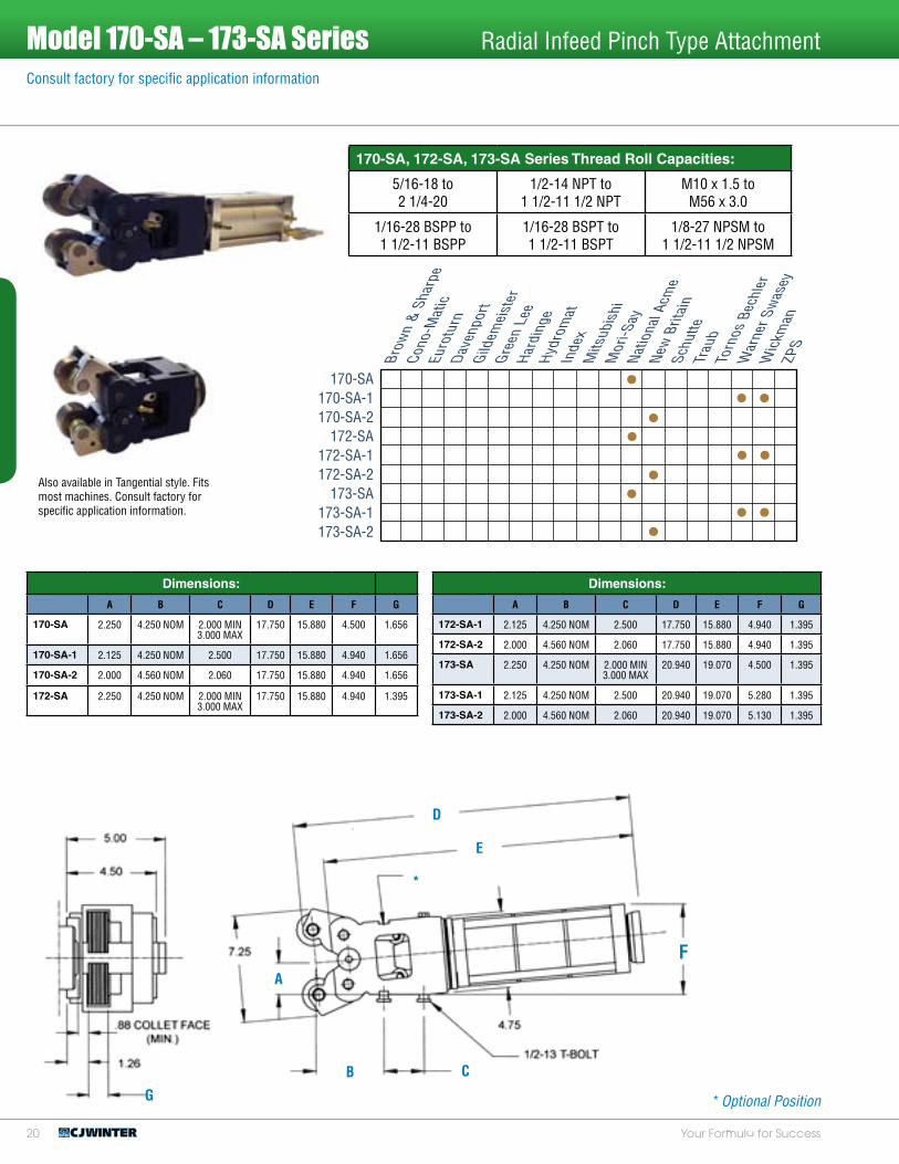
Model 170-SA – 173-SA Series Radial Infeed Pinch Type Attachment
170-SA, 172-SA, 173-SA Series Thread Roll Capacities:
5/16-18 to 2 1/4-20
1/2-14 NPT to 1 1/2-11 1/2 NPT
M10 x 1.5 to M56 x 3.0
1/16-28 BSPP to 1 1/2-11 BSPP
1/16-28 BSPT to 1 1/2-11 BSPT
1/8-27 NPSM to 1 1/2-11 1/2 NPSM
A
B C
F
D
E
Brow
n &
Sha
rpe
Cono
-Mat
icEu
rotu
rnD
aven
port
Gild
emei
ster
Gre
en L
eeH
ardi
nge
Hyd
rom
atIn
dex
Mits
ubis
hiM
ori-S
ayN
atio
nal A
cme
New
Brit
ain
Schu
tteTr
aub
Torn
os B
echl
erW
arne
r Sw
asey
Wic
kman
ZPS
170-SA170-SA-1170-SA-2
172-SA172-SA-1172-SA-2
173-SA173-SA-1173-SA-2
*
* Optional Position
Dimensions:
A B C D E F G
170-SA 2.250 4.250 NOM 2.000 MIN 3.000 MAX
17.750 15.880 4.500 1.656
170-SA-1 2.125 4.250 NOM 2.500 17.750 15.880 4.940 1.656
170-SA-2 2.000 4.560 NOM 2.060 17.750 15.880 4.940 1.656
172-SA 2.250 4.250 NOM 2.000 MIN 3.000 MAX
17.750 15.880 4.940 1.395
Dimensions:
A B C D E F G
172-SA-1 2.125 4.250 NOM 2.500 17.750 15.880 4.940 1.395
172-SA-2 2.000 4.560 NOM 2.060 17.750 15.880 4.940 1.395
173-SA 2.250 4.250 NOM 2.000 MIN 3.000 MAX
20.940 19.070 4.500 1.395
173-SA-1 2.125 4.250 NOM 2.500 20.940 19.070 5.280 1.395
173-SA-2 2.000 4.560 NOM 2.060 20.940 19.070 5.130 1.395
G

21www.cjwinter.comCall: 1-800-288-ROLL (7655) • Fax: 1-585-429-5095
This exclusive CJWinter process matches the large diameter of the thread roll to the large diameter of the blank to eliminate the mismatch of the thread rolls on the work piece, and the attachment “walking” on the part.
The patented “match taper” design helps eliminate flaking and slivering. The radial infeed and equalized thread rolling pressure eliminates part deflection to improve thread concentricity.
This system is available in the 134-SA, 151-SA and 162-SA models. A retrofit kit is also available for the 134-SA, 141-SA, 151-SA and 160-SA or larger attachments.
Consult factory for specific application information
Winter Pipe Thread Rolling System “Match Taper”
Match Taper Q2 Style Match Taper K2 Style

22 Your Formula for Success
The CJWinter Air Powered Outboard Radial Infeed Thread Rolling Attachment incorporates many of the same proven features currently found on the “Standard” and “Heavy Duty” CJWinter Thread Rolling Attachments.
The outboard type attachment is designed to roll threads on parts that are usually held where shoulder or stock clearances are critical.
Consult factory for specific application information
Model 145-OB &165-OB Outboard Series Radial Infeed Pinch Type Attachment
145-OB
165-OB
Dimensions:
A B C D E F G H
145-OB 1.312 6.09 NOM 3/8-16 T-BOLT 4.180 4.620 13.000 11.750 .625
165-OB 2.250 5.812 5/8 T-KEY 4.500 4.399 18.060 16.500 .750
165-OB-1 2.125 7.250 1/2-13 T-BOLT 4.940 5.060 18.060 16.500 .750
165-OB-2 2.000 7.062 1/2-13 T-BOLT 4.940 5.060 18.060 16.500 .750
A
B C
D
E
Brow
n &
Sha
rpe
Cono
-Mat
icEu
rotu
rnD
aven
port
Gild
emei
ster
Gre
en L
eeH
ardi
nge
Hyd
rom
atIn
dex
Mits
ubis
hiM
ori-S
ayN
atio
nal A
cme
New
Brit
ain
Schu
tteTr
aub
Torn
os B
echl
erW
arne
r Sw
asey
Wic
kman
ZPS
145-OB165-OB
165-OB-1165-OB-2
F
G
145-OB Series Thread Roll Capacities:
8-32 to 3/4-27
1/16-27 NPT to 3/8-18 NPT
M5 x 0.5 to M18 x 2.5
1/16-28 BSPP to 3/8-19 BSPP
1/16-28 BSPT to 3/8-19 BSPT
1/8-27 NPSM to 3/8-18 NPSM
165-OB Series Thread Roll Capacities:
5/16-20 to 1 5/16-32
1/16-27 NPT to 3/4-14 NPT
M6 x 1.0 to M33 x 1.5
1/16-28 BSPP to 3/4-14 BSPP
1/16-28 BSPT to 3/4-14 BSPT
1/8-27 NPSM to 3/4-14 NPSM
*
* Optional PositionH

2�www.cjwinter.comCall: 1-800-288-ROLL (7655) • Fax: 1-585-429-5095
NC41 Series Tangential Attachment for CNC ApplicationsConsult factory for specific application information
NC41
If you’re still cutting screw threads instead of rolling on a CNC machine, you should consider purchasing a CJWinter NC41 Tangential Attachment:
• Speed: Forms threads in a fraction of the time, part by part, job by job, adding up to significant time savings.
• Flexibility: Tool-free adjustment with our Pitch Diameter Knob, and Quick Release Mechanism for replacing rolls without tools.
• Reliability: Workhorse-tough construction and rapid service response that surpass your expectations.
• Strength: Roll threads for better quality and greater strength.
• Cost: We’re less expensive than our competitors. It’s as simple as that. Rolling eliminates chatter, and with the NC41, it also eliminates flaking, thanks to our patented Roll Compensator.
• Delivery: If you’re eager to get rolling, we’re the ones to call. You’ll find our delivery times impressive, even for customized orders.
• Options: Available with either a square or VDI shank configuration to adapt to most lathes.
• Durability: No universal mounts; our CNC attachments arrive with customized brackets for mounting on your specific machine.
• More Markets: Some customers (like aerospace) insist on rolled threads, because they’re stronger. Multiply your products’ potential market!
NC41 Series Range:
#0-80 to 3/4-32
1/16-27 NPT to 3/8-18 NPT
M1.4 x 0.3 to M18 x 2.5
Compatible Machine List
Mori-SeikiHardinge
GildemeisterCitizenTornosMiaynoOkumaMazakHaas
Call the factory for additional machines.
4.000 Bracket Height (101.600 mm)
3.435 (Max) To Turret Face (87.249 mm)
4.861 (Max) Across QR Levers (123.470 mm)
3.743 (95.072 mm) To Compensator
3.240 (82.296 mm) Bracket Width

24 Your Formula for Success
Consult factory for specific application information.
Detroit Style Attachments
Dimensions:
A B C D E F G H I
76200 .438 1.000 2.313 3.875 1.938 .625 2.500 1.563 1.500
76300 .438 1.000 2.313 4.500 2.250 .688 2.635 1.780 1.500
76400 .563 1.250 2.813 5.875 2.938 .875 2.813 2.063 2.500
77300 NA .875 4.375 5.875 2.938 .875 2.813 2.000 2.500
AB
C
D
Detroit (76200, 76300, 76400)
The Detroit Style Attachment offers an alternative to our customers who prefer the more traditional tangential rolling style. Completely re-engineered to the closest of manufacturing tolerances, our Detroit line is second to none in quality and reliability.
The 77300 Detroit Style Outboard Attachment has been re-engineered to provide the highest quality thread rolling when stock clearance is critical. Designed to roll threads close to the shoulder or parts that are being chucked, the Detroit Style Outboard Attachment is unsurpassed in thread quality and ease of set-up.
Brow
n &
Sha
rpe
Cono
-Mat
icEu
rotu
rnD
aven
port
Gild
emei
ster
Gre
en L
eeH
ardi
nge
Hyd
rom
atIn
dex
Mits
ubis
hiM
ori-S
ayN
atio
nal A
cme
New
Brit
ain
Schu
tteTr
aub
Torn
os B
echl
erW
arne
r Sw
asey
Wic
kman
ZPS
76200763007640077300
E
F G
H
I
BC
D
E
F G
H
I
Call factory for size capacity.
Detroit Outboard (77300)Detroit (76200, 76300, 76400)
Detroit Outboard (77300)

25www.cjwinter.comCall: 1-800-288-ROLL (7655) • Fax: 1-585-429-5095
High Speed Changeover on a Davenport!• Tool Spindles• Slides & Adapter
Plates • Form Tools• Shave Tools • Pre-Set Fixtures• Drill & Tap Holders
CJWinter. Your Formula for Success.CJWinter manufactures the premier line of thread rolling attachments, thread rolls
and specialty dies and tooling for multi-spindle and CNC machines. Our higher quality rolls, easily adjusted attachments and lower initial cost have been
our competitive edge for over 50 years. Our team of highly dedicated engineers focuses on solving every customer’s thread rolling and metal forming challenge,
resulting in world renowned customer service.
2714-QCT ..................... pg. 26
2714-ER-QCT................. pg. 26
2715-ER-QCT................. pg. 27
2716-ER-QCT................. pg. 27
111-14-QCT .................. pg. 28-29
111-15-QCT .................. pg. 30
111-16-DAV .................. pg. 31
3060-5-QCT .................. pg. 31
3060-10-QCT ................. pg. 32
3092-5-QCT .................. pg. 32
3092-10-QCT ................. pg. 33
335-U-SA-1125 .............. pg. 33
335-U-SA-1375 .............. pg. 34
335-U-SA-1656 .............. pg. 34
2717-QCT ..................... pg. 35
5080-99-2-QCT .............. pg. 35
132-A-QCT.................... pg. 36
132-B-QCT.................... pg. 36
Made in the USA
Quick Change Tooling
Tool Changeover in MinutesTool Changeover in Minutes

26 Your Formula for Success
2714-QCT Drill Holder
2714-ER-QCT ER 25 Drill Holder
1
2
3
1
2
Qty. Part Number Description1 1 2714-11 QCT Drill Holder 2 1 2714-9 SSS 3/8-24 x .375 Cup Pt.3 1 2714-8 SSS 3/8-24 x .500 Flat Pt.
Qty. Part Number Description1 1 2714-14 ER 25 Series Drill Holder2 1 2714-15 QCT ER 25 Collet Nut3 1 2714-8 SSS 3/8-24 x .500 Flat Pt.
Quick Change Tooling
3

27www.cjwinter.comCall: 1-800-288-ROLL (7655) • Fax: 1-585-429-5095
2715-ER-QCT ER 20 Drill Holder
2716-ER-QCT ER 16 Drill Holder
1
2
1
2
Qty. Part Number Description1 1 2715-14 QCT ER 20 Drill Holder2 1 2715-15 QCT ER 20 Collet Nut3 1 2714-8 SSS 3/8-24 x .500 Flat Pt.
Qty. Part Number Description1 1 2716-14 QCT ER 16 Drill Holder2 1 2716-15 QCT ER 16 Collet Nut3 1 2714-8 SSS 3/8-24 x .500 Flat Pt.
Quick Change Tooling
3
3

28 Your Formula for Success
111-14-QCT Shave Tool and 2nd Position Block
111-11-QCT 2nd Position Tool Block Assembly
Qty. Part Number Description1 1 111-01 Center Shave Tool Assembly2 1 111-11-QCT 2nd Pos. Tool Block Assembly
Qty. Part Number Description1 1 111006 Taper Arm - 2nd Pos.2 1 111008 Taper Pin (Arm)3 1 111009 Threaded Taper Adjust Pin (Block)4 1 111010 Taper Adjustment Screw5 1 111029 SSS #10-32 x 1.250 Cup Pt.6 1 111205 Tool Block7 1 111207 Expansion Locking Gib-Angled-(1st 2nd 3rd)8 2 125043 SSS #8-32 x .188 Cup Pt.9 1 130047 SHCS 5/16-24 x 1.00010 1 NC41029 Spring Plunger #8-32 Short, Heavy Force
1
5
4
8
2
7
6
9
bk
2
3
1
Quick Change Tooling

29www.cjwinter.comCall: 1-800-288-ROLL (7655) • Fax: 1-585-429-5095
111-01 Shave Tool Assembly
Qty. Part Number Description1 1 Setup Specific See *111-20 or *111-21 Below2 1 111000 Matched Assembly3 1 111014 Body Pin4 1 111015 Adjusting Screw5 1 111058 Running Expansion Gib Assembly6 2 111062 .125 Stainless Steel Ball7 1 108046 Dovetail Clamp - 1/2 & 5/8 Reversible8 1 108011 Spring: Compression, .300 OD x 1.0009 1 108017 SSS, 7/16-20 x .50010 1 108018 Stop Adjusting Screw11 1 108019 Nut: Jam 1/4-2012 2 108023 SHCS 1/4-28 x .62513 2 141368 SSS #8-32 x .250 Cup Pt.14 1 Shave Tool Insert Setup Specific – Not Included
7
5
111-20 Center Roll Holder Assembly
111-21 Inboard Roll Bracket Assembly
Qty. Part Number Description1 1 111120 Roll Holder - Center2 1 108047 Roller Pin, Centered3 1 108009 Roller - .750 Dia.4 2 108054 Shaft Collar5 1 108024 SSS #6-40 x .125 Long6 2 108055 SSS #6-32 x .188 Long
1
5
bm
1 2
4
bk
bl
3
bn6
8
9
bo
6
34
2
1
5
6
4
3
2
Qty. Part Number Description1 1 111121 Roller Holder - Inboard2 1 108015 Roller Pin, Centered3 1 108054 Shaft Collar4 1 108009 Roller - .750 Dia.5 2 108024 SSS #6-40 x .125 Long6 1 108055 SSS #6-32 x .188 Long
Quick Change Tooling

�0 Your Formula for Success
Quick Change Tooling
111-15 QCT Shave Tool and 3rd Position Block
111-12 3rd Position Tool Block Assembly
Qty. Part Number Description1 1 111-01 Center Shave Tool Assembly2 1 111-12 3rd Pos. Tool Block Assembly
Qty. Part Number Description1 1 111007 Taper Arm - 3rd Pos.2 1 111008 Taper Pin (Arm)3 1 111009 Threaded Taper Adjust Pin (Block)4 1 111010 Taper Adjustment Screw5 3 111026 FHCS #10-32 x .7506 1 111028 Pin: Dowel .250 x .6257 1 111201 Tool Block8 1 111202 Dovetail Adapter Plate (3rd)9 1 111207 Expansion Locking Gib-Angled (1st 2nd 3rd)10 2 125043 SSS #8-32 x .188 Cup Pt.11 1 111023 SSS #10-32 x .500 Cup Pt.12 1 111024 SSS #8-32 x .250 Flat Pt.13 2 130046 SHCS 5/16-24 x .62514 1 130047 SHCS 5/16-24 x 1.00015 1 NC41029 Spring Plunger #8-32 Short Heavy Force
1
2
bo
6
5080-1-111 Swing Arm (Sold separately)
bm
bk 1 2
3
5
bp
7
bl
4
9
bn
8

�1www.cjwinter.comCall: 1-800-288-ROLL (7655) • Fax: 1-585-429-5095
This Dovetail Tool Holder is used with 132-A-QCT 1st Position Cross Slide. It is designed for heavier cuts with a face angle of 5°. This holder uses an American Standard Dovetail Blank Group 2.
Quick Change Tooling
3060-5-QCT 1st Position Dovetail Tool Holder 5°
Qty. Part Number Description1 1 3060-3 Clamp2 1 3060-32 QCT Form Tool Base Block3 1 3060-33 QCT Dovetail Tool Block (5°)4 1 3060-43 Taper Adjustment Screw (Hex)5 4 3060-44 Bolt: Hex 1/4-28 x 1.7506 1 3060-46 Locking Gib7 4 108026 Washer: Flat .250 Dia.8 1 5080-99-45 SSS #10-32 x 1.000 Flat Pt.9 2 834-A-4 SHCS 5/16-24 x .62510 1 838-19 Pin: Spring .188 Dia. x .50011 1 838-92 Pin: Dowel .250 Dia. x .438
7
5
3
4
8
9
1
blbk
2
6
111-16-DAV Shave Tool and 3rd/4th Position Block
Qty. Part Number Description1 1 111-01 Center Shave Tool Assembly2 1 108203A Adapter Block Assembly
6
4
3
108203A 3rd and 4th Position Tool Block
51
2
1644-SA 3rd Pos. Cross Slide or 5080-281-29-SA 4th Pos. Cross Slide
Qty. Part Number Description3 1 108203 Adapter Block4 2 140294 SSS 1/4-28 x .7505 1 7999400 SSS 3/8-24 x 1.5006 1 140311 SHCS 3/8-16 x 1.000
�2 Your Formula for Success
Quick Change Tooling
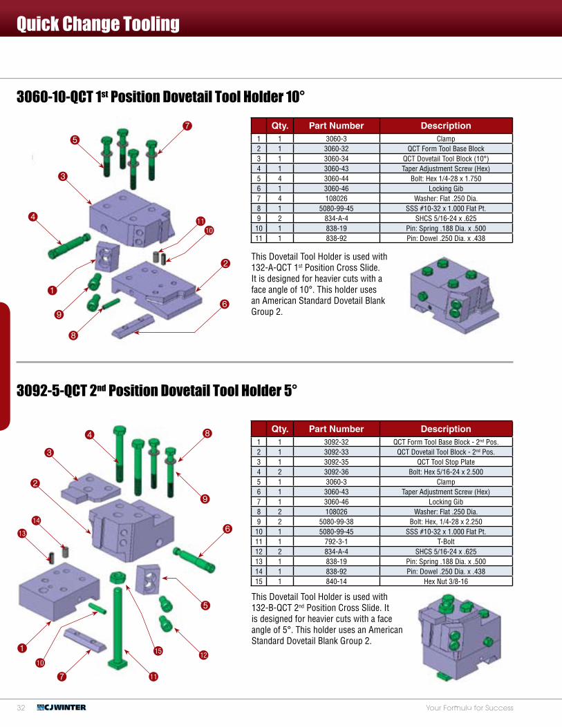
3060-10-QCT 1st Position Dovetail Tool Holder 10°
3092-5-QCT 2nd Position Dovetail Tool Holder 5°
Qty. Part Number Description1 1 3092-32 QCT Form Tool Base Block - 2nd Pos.2 1 3092-33 QCT Dovetail Tool Block - 2nd Pos.3 1 3092-35 QCT Tool Stop Plate4 2 3092-36 Bolt: Hex 5/16-24 x 2.5005 1 3060-3 Clamp6 1 3060-43 Taper Adjustment Screw (Hex)7 1 3060-46 Locking Gib8 2 108026 Washer: Flat .250 Dia.9 2 5080-99-38 Bolt: Hex, 1/4-28 x 2.25010 1 5080-99-45 SSS #10-32 x 1.000 Flat Pt.11 1 792-3-1 T-Bolt12 2 834-A-4 SHCS 5/16-24 x .62513 1 838-19 Pin: Spring .188 Dia. x .50014 1 838-92 Pin: Dowel .250 Dia. x .43815 1 840-14 Hex Nut 3/8-16
Qty. Part Number Description1 1 3060-3 Clamp2 1 3060-32 QCT Form Tool Base Block3 1 3060-34 QCT Dovetail Tool Block (10°)4 1 3060-43 Taper Adjustment Screw (Hex)5 4 3060-44 Bolt: Hex 1/4-28 x 1.7506 1 3060-46 Locking Gib7 4 108026 Washer: Flat .250 Dia.8 1 5080-99-45 SSS #10-32 x 1.000 Flat Pt.9 2 834-A-4 SHCS 5/16-24 x .62510 1 838-19 Pin: Spring .188 Dia. x .50011 1 838-92 Pin: Dowel .250 Dia. x .438
This Dovetail Tool Holder is used with 132-A-QCT 1st Position Cross Slide. It is designed for heavier cuts with a face angle of 10°. This holder uses an American Standard Dovetail Blank Group 2.
7
5
3
4
8
9
1
blbk
2
6
This Dovetail Tool Holder is used with 132-B-QCT 2nd Position Cross Slide. It is designed for heavier cuts with a face angle of 5°. This holder uses an American Standard Dovetail Blank Group 2.
4
3
bo
bn
1
7
bk
bl
bp bm
5
9
8
6
2
13
14
1
23
4
5
10
6
7
8
9
11
12
15
This Dovetail Tool Holder is used with 132-B-QCT 2nd Position Cross Slide. It is designed for heavier cuts witha face angle of 5 and is used for free cutting materials, some grades of aluminum or brass. This holder uses an American Standard Dovetail Blank Group 2.
ITEM NO. QTY. PART NO. DESCRIPTION
1 1 3092-32 Form Tool Base Block - 2nd Pos. (QCT)
2 1 3092-33 QCT Dovetail Tool Block - 2nd Pos
3 1 3092-35 Tool Stop Plate (QCT)
4 2 3092-36 Bolt: Hex, 5/16-24 x 2.50
5 1 3060-3 Clamp
6 1 3060-43 Taper Adjustment Screw (Hex)
7 1 3060-46 Locking Gib
8 2 108026 Washer: Flat, .250 dia. (1/4")
9 2 5080-99-38 Bolt: Hex, 1/4-28 x 2.25
10 1 5080-99-45 Screw: SSS, #10-32 x 1.00 Flat Pt.
11 1 792-3-1 T-Bolt
12 2 834-A-4 Screw: SHCS, 5/16 - 24 x .625
13 1 838-19 Pin: Spring, .188 dia x .500
14 1 838-92 Pin: Dowel, .250 Dia x .4375
15 1 840-1 Nut: Hex, 3/8-16 x 1/4 Lg x 5/8 Hex
8
9
10
1
2
3
4
5
6
7
11
ITEM NO. QTY. PART NO. DESCRIPTION
1 1 3060-3 Clamp
2 1 3060-32 Form Tool Base block (QCT)
3 1 3060-34 QCT Dovetail Tool Block (10 Deg)
4 1 3060-43 Taper Adjustment Screw (Hex)
5 4 3060-44 Bolt: Hex, 1/4-28 x 1.75
6 1 3060-46 Locking Gib
7 4 108026 Washer: Flat, .250 dia. (1/4")
8 1 5080-99-45 Screw: SSS, #10-32 x 1.00 Flat Pt.
9 2 834-A-4 Screw: SHCS, 5/16 - 24 x .625
10 1 838-19 Pin: Spring, .188 dia x .500
11 1 838-92 Pin: Dowel, .250 Dia x .4375
This Dovetail Tool Holder is used with 132-A-QCT 1st Position Cross Slide.It is designed for heavier cuts with a face angle of 10 and is used for cutting steel materials. This holder uses an American Standard Dovetail Blank Group 2.

��www.cjwinter.comCall: 1-800-288-ROLL (7655) • Fax: 1-585-429-5095
Quick Change Tooling
335-U-SA-1125 Universal Tool Spindle Front Box
Qty. Part Number Description1 1 335-U Front Box Sleeve2 1 335-UB-1125 Drill/Threading Spin Bearing3 1 639-1 Spin Thrust Brg. Nut4 1 834-A-4-2 SHCS #4-40 x .125 Long5 1 834-A-5.40-6 SHCS #6-40 x .375 Long
3092-10-QCT 2nd Position Dovetail Tool Holder 10° Qty. Part Number Description
1 1 3092-32 QCT Form Tool Base Block - 2nd Pos.2 1 3092-34 QCT Dovetail Tool Block - 2nd Pos.3 1 3092-37 QCT Tool Stop Plate4 2 3092-36 Bolt: Hex 5/16-24 x 2.5005 1 3060-3 Clamp6 1 3060-43 Taper Adjustment Screw (Hex)7 1 3060-46 Locking Gib8 2 108026 Washer: Flat .250 Dia.9 2 5080-99-38 Bolt: Hex 1/4-28 x 2.25010 1 5080-99-45 SSS #10-32 x 1.00 Flat Pt.11 1 792-3-1 T-Bolt12 2 834-A-4 SHCS 5/16-24 x .62513 1 838-19 Pin: Spring .188 Dia. x .50014 1 838-92 Pin: Dowel .250 Dia. x .43815 1 840-14 Hex Nut 3/8-16
The Universal Tool Spindle Front Box for the stationary head is primarily used for drill or threading spindles. Once the outer sleeve is properly fitted in the front bore of the stationary head, the inner bearing can be changed to accommodate other spindle diameters without disturbing spindle alignment. This feature can reduce time when switching from 1.125, 1.375 and 1.656 diameter spindles.
This Dovetail Tool Holder is used with 132-B-QCT 2nd Position Cross Slide. It is designed for heavier cuts with a face angle of 10°. This holder uses an American Standard Dovetail Blank Group 2.
4
3
bo
bn
1
7
bk
bl
bp bm
5
9
8
6
2
3
4
5
2
This Dovetail Tool Holder is used with 132-B-QCT 2nd Position Cross Slide. It is designed for heavier cuts with a face angle of 10 and is used for cutting steel materials. This holder uses an American Standard Dovetail Blank Group 2.
4
8
13
11
5
9
146
23
1
7
10
12
15
ITEM NO. QTY. PART NO. DESCRIPTION
1 1 3092-32 Form Tool Base Block - 2nd Pos. (QCT)
2 1 3092-33 QCT Dovetail Tool Block - 2nd Pos
3 1 3092-35 Tool Stop Plate (QCT)
4 2 3092-36 Bolt: Hex, 5/16-24 x 2.50
5 1 3060-3 Clamp
6 1 3060-43 Taper Adjustment Screw (Hex)
7 1 3060-46 Locking Gib
8 2 108026 Washer: Flat, .250 dia. (1/4")
9 2 5080-99-38 Bolt: Hex, 1/4-28 x 2.25
10 1 5080-99-45 Screw: SSS, #10-32 x 1.00 Flat Pt.
11 1 792-3-1 T-Bolt
12 2 834-A-4 Screw: SHCS, 5/16 - 24 x .625
13 1 838-19 Pin: Spring, .188 dia x .500
14 1 838-92 Pin: Dowel, .250 Dia x .4375
15 1 840-1 Nut: Hex, 3/8-16 x 1/4 Lg x 5/8 Hex
1

�4 Your Formula for Success
Quick Change Tooling
335-U-SA-1656 Universal Tool Spindle Front Box
Qty. Part Number Description1 1 335-U Front Box Sleeve2 1 335-UB-1656 O/S Tool Spin Bearing3 1 639-1 Spin Thrust Bearing Nut4 1 834-A-4-2 SHCS #4-40 x .250 Long5 1 840-RE-42 Retaining Ring
This Universal Tool Spindle Front Box for the stationary head is primarily used for 1.656 diameter tool spindles or attachment spindles of the same diameters. Once the outer sleeve is properly fitted in the front bore of the stationary head, the inner bearing can be changed to accommodate other spindle diameters without disturbing spindle alignment. This feature can reduce time when switching from 1.125, 1.375 and 1.656 diameter spindles.
335-U-SA-1375 Universal Tool Spindle Front Box
Qty. Part Number Description1 1 335-U Front Box Sleeve2 1 335-UB-1375 Std. Tool Spin Bearing3 1 639-1 Spin Thrust Bearing Nut4 1 834-A-4-2 SHCS #4-40 x .125 Long5 1 834-A-5.40-6 SHCS #6-40 x .375 Long
This Universal Tool Spindle Front Box for the stationary head is primarily used for 1.375 diameter tool spindles or attachment spindles of the same diameter. Once the outer sleeve is properly fitted in the front bore of the stationary head, the inner bearing can be changed to accommodate other spindle diameters without disturbing spindle alignment. This feature can reduce time when switching from 1.125, 1.375 and 1.656 diameter spindles.
2
3
5
2
3
4
4
1
1
5
�5www.cjwinter.comCall: 1-800-288-ROLL (7655) • Fax: 1-585-429-5095
Quick Change Tooling
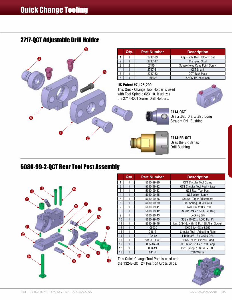
5080-99-2-QCT Rear Tool Post AssemblyQty. Part Number Description
1 1 5080-99-30 QCT Circular Tool Clamp2 1 5080-99-32 QCT Circular Tool Post - Base3 1 5080-99-33 QCT Rear Tool Post4 1 5080-99-35 QCT Worm Screw5 1 5080-99-36 Screw - Taper Adjustment6 1 5080-99-39 Pin: Spring, .094 x .5007 1 5080-99-41 Dowel Pin .250 x .7508 1 5080-99-42 SSS 3/8-24 x 1.500 Half Dog9 1 5080-99-43 Locking Gib10 1 5080-99-45 SSS #10-32 x 1.000 Flat Pt.11 1 5080-99-46 Nut: 3/8-16, with 12 Pt .188 Allen Socket12 1 109030 SHCS 1/4-28 x 1.75013 1 716-2 Circular Tool - Adjusting Plate14 1 792-12 T-Bolt: 3/8-16 x 3.000 OAL15 1 834-A-11-36 SHCS 1/4-28 x 2.250 Long16 1 835-16-28 HHCS 7/16-14 x 1.750 Long17 1 838-19 Pin: Spring .188 Dia. x .50018 1 841-7 7/16 Washer
bp
3
5
7
8
6
bm4
bl
br
2
bo9
bk bn1
bq
bs
This Quick Change Tool Post is used with the 132-B-QCT 2nd Position Cross Slide.
1
This quick Change Tool Post is used with the 132-B-QCT 2nd Position Cross Slide.
4
3
2
5
17
7
6
8
9
10
11
13
14
15
1618
12
ITEM NO. QTY. PART NO. DESCRIPTION
1 1 5080-99-30 Circular Tool Clamp (QCT)
2 1 5080-99-32 Circular Tool Post - Base (QCT)
3 1 5080-99-33 Rear Tool Post (QCT)
4 1 5080-99-35 Worm Screw (QCT)
5 1 5080-99-36 Screw - Taper Adjustment
6 1 5080-99-39 Pin: Spring, .094 x .500
7 1 5080-99-41 Dowel Pin .250 x .750
8 1 5080-99-42 Screw: SSS, 3/8-24 x 1.500, Half Dog
9 1 5080-99-43 Locking Gib
10 1 5080-99-45-1 Screw: SSS, #10-32 x 1.00 Flat Pt.
11 1 5080-99-46 Nut: 3/8-16, w/12PT .188 Allen Socket
12 1 109030 Screw: SHCS, 1/4-28 x 1.750
13 1 716-2 Circular Tool - Adjusting Plate
14 1 792-12 T-Bolt: 3/8-16 x 3.00 OAL
15 1 834-A-11-36 SHCS #1/4-28 X 2-1/4 LONG
16 1 835-16-28 HHCS 7/16-14 X 1-3/4"LG.
17 1 838-19 Pin: Spring, .188 dia x .500
18 1 841-7 7/16 WASHER
2717-QCT Adjustable Drill Holder
Qty. Part Number Description1 1 2717-33 Adjustable Drill Holder Front2 2 2717-17 Clamping Stud3 2 2486-1 Square Head Cone Point Screw4 1 2717-31 QCT Shank5 1 2717-32 QCT Back Plate6 1 160022 SHCS 1/4-28 x .875
4
1
5
3
6
2
2714-QCT Use a .625 Dia. x .875 Long Straight Drill Bushing
2714-ER-QCT Uses the ER Series Drill Bushing
US Patent #7,125,209 This Quick Change Tool Holder is used with Tool Spindle 623-10. It utilizes the 2714-QCT Series Drill Holders.

�6 Your Formula for Success
132-A-QCT Slide 1st Position Qty. Part Number Description1 1 132-A-QCT QCT Slide - 1st Pos. - Modified 1322 1 111204-A Quick Change Dovetail Adapter - 1st Pos.3 1 132004 Spring Screw for 132EG4 1 132005 Spring: Compression .588 OD x 1.2505 12 132006 FHCS, #6-32 x .2506 2 132007 BHCS #10-32 x .2507 1 132008 Base Endcap for 132EG8 1 132009 Spring Retainer for 132EG9 1 132010 Chip Guard 132 A Pos.10 1 132012 Drive Pin 132 A Pos.11 1 132013 Drive Pin 132 B Pos.12 1 132014 Nut: Hex, #10-32 with Nylon Insert13 2 132015 SSS 5/16-24 x .500 Cup Pt14 2 132024 SSS 5/16-24 x 1.000 Full Dog15 1 132058 Gib - Expansion Style16 1 132066 T-Slot Cover17 1 140280 SSS 1/4-28 x .250 Half Dog18 4 140366 LHCS 3/8-16 x .75019 4 3060-45 LHCS 1/4-28 x .75020 1 5080-91-G-1 Front Cross Slide Guard21 1 5080-99-44 Stop Pin
bt
bk 5
9
1
bq
5
clbr6
bn
ck
bo
5
78
bm 4
bl3
bp bs
2
2
3
5
7
8
9
10
11
12
13
14
20
21
16
1
4
5
1518
5
6
17 19
ITEM NO. QTY. PART NO. DESCRIPTION1 1 132-A-QCT QCT Slide - 1st Pos - Modified 1322 1 111204-A Quick Change Dovetail Adapter - 1st Pos.3 1 132004 Spring Screw for 132 EG4 1 132005 Spring: Compression, .588 OD x 1.255 14 132006 Screw: FHCS, #6-32 x .2506 2 132007 Screw: BHCS, #10-32 x .2507 1 132008 Base Endcap for 132 EG8 1 132009 Spring Retainer for 132 EG9 1 132010 Chip Guard 132 -A- Position
10 1 132012 Drive Pin 132 -A- Position11 1 132013 Drive Pin 132 -B- Position12 1 132014 Nut: Hex, #10-32 w/Nylon Insert13 2 132015 Screw: SSS, 5/16-24 x .50 Cup Pt.14 2 132024 Screw: SSS, 5/16-24 x 1.00 Full Dog15 1 132058 Gib - Expansion Style16 2 132066 T-Slot Cover17 1 140280 Screw: SSS, 1/4-28 x .250 Half Dog18 4 140366 Screw: LHCS, 3/8-16 x .75019 4 3060-45 Screw: LHCS, 1/4-28 x .75020 1 5080-91-G-1 FRONT CROSS SLIDE GUARD21 1 5080-99-44 STOP PIN
132-B-QCT Slide 2nd Position Qty. Part Number Description1 1 132-B-QCT QCT Slide - 2nd Pos. - Modified 1322 1 111204-B Quick Change Dovetail Adapter – 2nd Pos.3 1 132004 Spring Screw for 132EG4 1 132005 Spring: Compression .588 OD x 1.2505 12 132006 FHCS #6-32 x .2506 2 132007 BHCS #10-32 x .2507 1 132008 Base Endcap for 132EG8 1 132009 Spring Retainer for 132EG9 1 132011 Chip Guard 132 B Pos.10 1 132012 Drive Pin 132 A Pos.11 1 132013 Drive Pin 132 B Pos.12 1 132014 Nut: Hex #10-32 with Nylon Insert13 2 132015 SSS 5/16-24 x .500 Cup Pt. 14 2 132024 SSS 5/16-24 x 1.000 Full Dog 15 1 132058 Gib - Expansion Style 16 1 132066 T-Slot Cover17 1 140280 SSS 1/4-28 x .250 Half Dog 18 4 140366 LHCS 3/8-16 x .75019 4 3060-45 LHCS 1/4-28 x .75020 1 5080-99-44 Stop Pin
ck
bs
5
1
9
2bl
bt
6br
bp
bq
34bk
bm
85
bobn
Quick Change Tooling
7

�7www.cjwinter.comCall: 1-800-288-ROLL (7655) • Fax: 1-585-429-5095
2717-SA ..................... pg. 382763-10-SA ................. pg. 382720-SA ..................... pg. 392527-SA ..................... pg. 392768-SA ..................... pg. 402904-10-SA ................. pg. 402994-SA ..................... pg. 413089-1-SA ................... pg. 413092-5-SA ................... pg. 423060-5-SA ................... pg. 423060-10-SA ................. pg. 432714-SA ..................... pg. 432716-SA ..................... pg. 443264-20-SA ................. pg. 442729-SA ..................... pg. 45
2730-SA ..................... pg. 452730-23-SA ................. pg. 462791-SA ..................... pg. 462736-SA ..................... pg. 472737-SA ..................... pg. 473289-SA ..................... pg. 482801-SA ..................... pg. 483096-SA ..................... pg. 492726-O-SA .................. pg. 492726-R-SA .................. pg. 502810-SA ..................... pg. 502726-29-1500-O-SA .......pg. 512726-29-1500-R-SA .......pg. 512747-116-SA ................ pg. 522910-5-SA ................... pg. 52
2738-1-SA ................... pg. 532744-1-SA ................... pg. 533119-SA ..................... pg. 542785-1-SA ................... pg. 542800-SA ..................... pg. 552700-4-SA ................... pg. 552794-2-SA ................... pg. 563154-8-SA ................... pg. 56108 Shave Tool .............pg. 57109 Shave Tool .............pg. 57111 Shave Tool .............pg. 58131-EG Series .............. pg. 59132-EG Series .............. pg. 60
CJWinter Machine Technologies provides a full-line of American-made slides and tool holders for CNC turning centers, Swiss, multi-spindle and many other machines.
Our Slides and Tool Holders Feature Innovative Design That Provides:
Maximum life and reliability
Maximum compatibility with multiple manufacturers
Maximum usability from apprentice to journeyman
Get the high-quality product you expect from CJWinter with performance you can rely on. You just can’t find a more versatile line of products that provide quick mounting, easy adjustment, and solid, hardened steel construction. Our tough products make CJWinter an easy choice.
Made in the USA
Tool Holders Slides
Accessories
�8 Your Formula for Success
Davenport Tool Holders
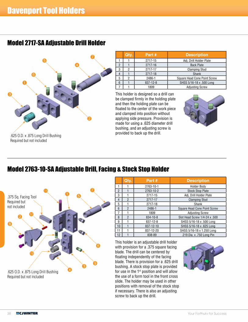
This holder is designed so a drill can be clamped firmly in the holding plate and then the holding plate can be floated to the center of the work piece and clamped into position without applying side pressure. Provision is made for using a .625 diameter drill bushing, and an adjusting screw is provided to back up the drill.
Model 2717-SA Adjustable Drill Holder
Qty. Part # Description1 1 2717-15 Adj. Drill Holder Plate2 1 2717-16 Back Plate3 2 2717-17 Clamping Stud4 1 2717-18 Shank5 2 2486-1 Square Head Cone Point Screw6 1 837-12-8 SHSS 5/16-18 x .500 Long7 1 1809 Adjusting Screw
Model 2763-10-SA Adjustable Drill, Facing & Stock Stop Holder
This holder is an adjustable drill holder with provision for a .375 square facing blade. The drill can be centered by floating independently of the facing blade. There is provision for a .625 drill bushing. A stock stop plate is provided for use in the 1st position and will allow the use of a form tool in the front cross slide. The holder may be used in other positions with removal of the stock stop if necessary. There is also an adjusting screw to back up the drill.
Qty. Part # Description1 1 2763-10-1 Holder Body2 1 2763-10-2 Stock Stop Plate3 1 2717-15 Adj. Drill Holder Plate4 2 2717-17 Clamping Stud5 1 2717-18 Shank6 2 2486-1 Square Head Cone Point Screw7 1 1809 Adjusting Screw8 2 834-10-8 Slot Head Screw 1/4-24 x .5009 1 837-12-8 SHSS 5/16-18 x .500 Long10 1 837-12-10 SHSS 5/16-18 x .625 Long11 1 837-12-20 SHSS 5/16-18 x 1.250 Long12 1 838-89 .219 Dia. x .750 Long Pin
1
3
6
4
7
8
2bm
bl
5
71
bk
43
9
6
.625 O.D. x .875 Long Drill Bushing Required but not included
.375 Sq. Facing Tool Required but not included
5
2
.625 O.D. x .875 Long Drill Bushing Required but not included

�9www.cjwinter.comCall: 1-800-288-ROLL (7655) • Fax: 1-585-429-5095
43
1
2
3
1
Selected Yoke to Fit Die Head Size
Davenport Tool Holders
Model 2720-SA Centering and Facing Tool Holder
A non-floating drill holder with provision for a .375 square facing blade and a .625 diameter drill bushing. A stock stop plate is provided for use in the 1st position and will allow the use of a form tool in the front cross slide. The holder has an adjusting screw in the shank to back up the drill.
Qty. Part # Description1 1 2720-1 Holder Body2 1 2720-4 Stock Stop Plate3 1 1803 Bushing Screw4 1 1809 Adjusting Screw5 2 834-L-9-8 LHCS 1/4-20 x .500 Long6 1 837-12-10 SHSS 5/16-18 x .625 Long7 1 837-12-12 SHSS 5/16-18 x .750 Long8 1 838-89 .219 Dia. x .750 Long Pin
Model 2527-SA Die Opening & Closing Stud Assembly
This attachment is used for the opening and closing of rotating die heads. For yoke required, specify make and model of die head to be used.
Qty. Part # Description1 2 2527-4-1 Stop Collar2 1 2527-16 Yoke Stud3 2 837-12-7 SHSS 5/16-18 x .437 Long4 1 840-18-1 Hex Nut 1/2-13 (Thin)
2
3
74
1
58
6
.375 Sq. Tool Required but not included
.525 O.D. x .875 Long Drill Bushing Required but not included

40 Your Formula for Success
Davenport Tool Holders
Model 2768-SA Rectangular Cutoff Tool Holder
A general purpose cutoff tool holder for the 5th position. Cutoff blades for this holder are available in the following widths: .031, .046, .062, .093, and .125.
Model 2904-10-SA Stationary Stock Stop Assembly
This stock stop fastens directly into the 3/4-16 tapped hole on the face of the stationary head. This allows for the use of an adjustable drill holder in the 1st position or other tooling such as a revolving drill.
Qty. Part # Description1 1 2768-1 Bottom Plate2 1 2768-2 Top Plate3 2 834-L-9-10 LHCS 1/4-20 x .625 Long4 1 838-35 Pin .140 Dia. x .375 Long5 1 841-S-4 .250 Soft Washer
41
52
3
.062 x .500 HSS cutoff blade
.5° taper per side (4.5 Long) (not included)
Qty. Part # Description1 1 2904-10 Stock Stop Body2 1 2904-11 Stock Stop Shank3 1 2904-12 Stock Stop Plate4 2 834-2-8 FHCS H-32 x .500 Long5 2 837-12-8 SHSS 5/16-18 x .500 Long6 2 840-1-24 Hex Nut 3/4-16
2
1
3
4
5
6

41www.cjwinter.comCall: 1-800-288-ROLL (7655) • Fax: 1-585-429-5095
Model 3089-1-SA Broach Tool Holder
Davenport Tool Holders
Model 2994-SA Front Tool Arm Stop Assembly
This is an independent stop for use in conjunction with the burring attachment when forming the left end of the work piece at the cutoff operation. A hardened stop is mounted on the revolving head cap and the other block is mounted onto the cutoff arm 459. Use the adjusting screw located on the swing arm block for setting adequate pressure to eliminate backlash.
Qty. Part # Description1 1 2994-1 Stop Plate2 1 2994-2 Front Tool Arm Plate3 1 835-14-24 HHCS 3/8-16 x 1.500 Long4 2 836-B-12-16 BHCS 5/16-18 x 1.000 Long5 1 837-12-16 SHSS 5/16-18 x .875 Long6 1 838-SP-6-24 .187 Dia. x 1.500 Long Roll Pin7 1 840-12 Hex Nut 5/16-18
The broach holder is used in conjunction with the 1381-38-SA REV-N-LOC Attachment. There are four adjusting screws to center the broach and a backup screw to take the thrust of the broaching operation. The holder uses a broach with a circular shank .375 diameter. The 3089-2-SA is the same as this holder except it uses a broach with a .250 diameter shank and (4) 10-32 screws.
Qty. Part # Description1 1 3089-1 Broach Holder2 1 1809 Adjusting Screw3 4 836-A-11-6 HSSS 1/4-28 x .375 Long
16
2
4
5
7
1
3
2
3

42 Your Formula for Success
Davenport Tool Holders
Model 3092-5-SA 2nd Position Dovetail Tool Holder
The 2nd Position Dovetail Tool Holder is designed for heavier forming operations. The dovetail form tool is ground for a 5° face angle and a desired rake angle. The tool is set approximately 10% above center at the cutting edge of the smallest diameter being worked. The holder uses an American Standard Dovetail Blank Group 2. The tool may be fitted with a set screw (1/4-28) for setting adjustment and to take the thrust of the cutting force.
Qty. Part # Description1 1 3092-5 5˚ Dovetail Body2 1 3092-5-1 Tool Stop Plate3 1 3092-10-2 Rising Block4 1 3060-3 Clamp5 1 3060-7 Taper Adjusting Screw6 2 792-3-1 Tool Post Bolt7 2 834-A-12-10 SHCS 5/16-18 x .625 Long8 1 837-10-18 SHSS 1/4-24 x 1.125 Long9 1 838-73 Pin .250 Dia. x .625 Long10 1 838-SP-6-12 Spring Pin .187 Dia. x .750 Long11 2 840-14 Hex Nut 3/8-16
Model 3060-5-SA 1st Position Dovetail Tool Holder
The 1st Position Dovetail Tool Holder is designed for heavier forming operations. It is used for free cutting grades of aluminum, brass and steel. The dovetail form tool is ground for a 5° face angle and a desired rake angle. The tool is set approximately 10% above center at the cutting edge of the smallest diameter being worked. The holder uses an American Standard Dovetail Blank Group 2. The tool may be fitted with a set screw (1/4-28) for setting adjustment and to take the thrust of the cutting force.
Qty. Part # Description1 1 3060-5 5° Dovetail Body2 1 3060-3 Tool Clamp3 1 3060-6 Rising Block4 1 3060-7 Taper Adjusting Screw5 2 792-4 Tool Post Bolt6 2 834-A-13-10 SHCS 5/16-24 x .625 Long7 1 837-9-20 SHSS 1/4-24 x 1.250 Long8 1 838-SP-6-8 Spring Pin .187 Dia. x .500 Long9 1 838-72 Pin .250 Dia. x .500 Long10 2 840-14 Hex Nut 3/8-1611 2 841-6 .375 Washer
3
6
bk
1
5
82
bl
4
7
4
1
7
bl
bk
2
65
3
9
This holder is also available for a 10° face angle form tool 3092-10-SA. Used for steel materials requiring more face clearance.
8
Group #2 American Dovetail Tool Blank 1.56 Length (not included)
9

4�www.cjwinter.comCall: 1-800-288-ROLL (7655) • Fax: 1-585-429-5095
Davenport Tool Holders
Model 2714-SA Drill Holder
Model 3060-10-SA 1st Position Dovetail Tool Holder
The 1st Position Dovetail Tool Holder is designed for heavier forming operations. The dovetail form tool is ground for a 10° face angle and a desired rake angle. The tool is set approximately 10% above center at the cutting edge of the smallest diameter being worked. The holder uses an American Standard Dovetail Blank Group 2. The tool may be fitted with a set screw (1/4-28) for setting adjustment and to take the thrust of the cutting force.
Qty. Part # Description1 1 3060-10 10˚ Dovetail Body2 1 3060-3 Clamp3 1 3060-6 Rising Block4 1 3060-7 Taper Adjusting Screw5 2 792-4 Tool Post Bolt6 2 834-A-13-10 SHCS 5/16-24 x .625 Long7 1 837-9-20 SHSS 1/4-24 x 1.250 Long8 1 838-SP-6-8 Spring Pin .187 Dia. x .375 Long9 1 838-72 Pin .250 Dia. x .500 Long10 2 840-14 Hex Nut 3/8-1611 2 841-6 .375 Washer
4
1
7bk
2
6
5
3
bl
8Group #2 American Std. Dovetail Blank 1.62 Length (not included)
9
This drill holder can be used in rotating or non-rotating tool spindles. Provision is made for a .625 diameter drill bushing .875 long. An adjusting screw is provided to back up the drill.
Qty. Part # Description1 1 2714 Drill Holder2 1 1809 Adjusting Screw3 1 836-A-14-6 HSSS 3/8-16 x .375 Long2
3
3

44 Your Formula for Success
Davenport Tool Holders
Model 2716-SA Drill Holder with Stock Stop
This holder is designed for the 1st position with a hardened stock stop plate and has provision for a .625 inch drill bushing. An adjusting screw is provided to back up the drill.
Qty. Part # Description1 1 2716-1 Drill Holder2 1 2716-2-10 Stock Stop for Drill Holder3 2 834-L-9-8 LHCS 1/4-20 x .500 Long4 1 837-12-12 SHSS 5/16-18 x .750 Long5 1 1809 Adjusting Screw
Model 3264-20-SA Dovetail Skive Tool Holder
4
5
2
1
3
Qty. Part # Description1 1 3264-20-1 Body2 1 3264-20-2 Skive Dovetail Mount3 1 3264-20-3 Adjusting Screw4 1 3264-20-4 Adjusting Plug5 1 3264-20-5 Spring6 1 3264-20-6 Tool Clamp7 1 3264-20-7 Brass Guide Bushing8 1 3154-4 Stat. Tool Clamp Segment9 1 3154-5 Tool Clamp10 2 834-A-11-8 SHCS 1/4-28 x .500 Long11 2 834-A-11-10 SHCS 1/4-28 x .625 Long12 1 836-A-8-6 HSSS #10-32 x .375 Long13 2 836-B-11-8 BHSS 1/4-28 x .500 Long
4bm27
5
1bn
8
3bk
bl
6
9
The Dovetail Skive Tool Holder is used for forming a long part while exerting the least amount of force from a cross slide position. Its purpose is to perform a wide forming operation without bending or breaking off the work piece. This is accomplished by the tool having an angular cutting face thereby gaining the benefit of full stock size at the exact point of the machining operation. The tool feeds across the work piece tangentially to center and doesn’t require any corrective tool step calculations.
.625 O.D. x .875 Long Drill BushingRequired but not included

45www.cjwinter.comCall: 1-800-288-ROLL (7655) • Fax: 1-585-429-5095
Davenport Tool Holders
Model 2729-SA Knurl Holder
The Single Knurl Roll Holder is used for bump knurling in the 2nd, 3rd, or 4th position.
Qty. Part # Description1 1 2729 Body2 1 773-4-13 .250 x 1.187 Long Tool Stl. Pin3 1 836-A-8-6 HSSS #10-32 x .375 Long4 1 838-35 Pin .140 Dia. x .375 Long
Model 2730-SA Double Knurl Tool Holder
This holder uses two knurls for diamond or straight knurling. The knurl rolls for this holder are .625 O.D. by .250 I.D. by .250 wide. This holder can be used for straightening. Optional carbide roll pins are available.
4
13
2
Used with .625 or .750 Dia. Knurl .250 Wide x .250 I.D.
(not included)
Qty. Part # Description1 1 2730-1 Clamp Plate2 1 2730-2 Top Knurl Arm3 1 2730-3 Bottom Knurl Arm4 2 2730-5 Carbide Pin .250 Dia. (Optional)5 2 2730-6 Knurl Arm Bushing6 1 2730-7 Rocker - Knurl Arm7 1 2730-8 Nut - Knurl Arm8 1 2730-9 Spring9 2 773-4-11 .250 x .687 Long Tool Stl. Pin10 1 835-14-40 HHCS 3/8-16 x 2.500 Long11 2 836-A-8-4 HSSS #10-32 x .250 Long12 2 836-A-8-3 HSSS #10-32 x .187 Long13 1 838-35 Pin .140 x .375 Long14 2 838-77 Soft Pin .250 x 1.250 Long
1
bk
bn
bm
5
bo
7
3
bl
8
6
2
9
bl
9
4()
4()

46 Your Formula for Success
Model 2791-SA Letter Roll Holder
Bump style letter roll holder with self returning spring. Driving dots added to the letter roll start its rotation. Once the tool is released the roll returns to start position.
Qty. Part # Description1 1 2791-1 Letter Roll Holder2 1 2791-2 Letter Roll Pin3 1 2791-3 Spring Sleeve4 1 2791-4 Stop Pin5 1 2791-7 Latch Spring6 1 838-35 Pin .140 Dia. x .375 Long7 1 836-A-10-4 HSSS 1/4-24 x .250 Long
Model 2730-23-SA Knurl Tool Holder Wide, Oversize
6
1
4
5
2
37
Davenport Tool Holders
This holder uses two knurls for diamond or straight knurling. The knurl rolls for this holder are .750 O.D. by .250 I.D. The knurl width can be .250 using spacers or .375 without spacers. This holder can also be used for bar straightening.
Qty. Part # Description1 1 2730-23-1 Top Knurl Arm2 1 2730-23-2 Bottom Knurl Arm3 2 2730-23-3 Spacer .125 Wide4 1 2730-1 Clamp Plate5 2 2730-6 Knurl Arm Bushing6 1 2730-7 Rocker - Knurl Arm7 1 2730-8 Nut - Knurl Arm8 1 2730-9-1 Compression Spring9 2 773-4-13 .250 x 1.187 Long Tool Stl. Pin10 1 835-12-40 Hex Bolt 5/16-18 x 2.500 Long11 2 836-A-8-3 HSSS #10-32 x .187 Long12 2 836-A-8-4 HSSS #10-32 x .250 Long13 1 838-35 Pin .140 Dia. x .375 Long14 2 838-77 .250 x 1.250 Soft Pin
4
bk
1bl
5
bo
7
2
8
6
bm
3
9
bn
Letter Roll & Set Screw Special Per S.U..625 O.D. x .250 I.D. .249 Wide
bm

47www.cjwinter.comCall: 1-800-288-ROLL (7655) • Fax: 1-585-429-5095
Model 2736-SA Pointing Tool Holder with Support Rolls
This holder is used to form the end face of a part. Provision is made for a circular form tool up to 1.125 diameter. Roller back rests are provided for a part diameter of .175 to .500.
Qty. Part # Description1 1 2736 Holder Body2 1 2736-1 Cutter Stud3 1 2737-4 Clamp Shoe4 2 2503 Roll .406 Dia.5 2 2503-2 Roll Pin6 2 2522 Roll Holder7 1 836-A-8-4 HSSS #10-32 x .250 Long8 1 836-A-8-10 HSSS, #10-32 x .625 Cup Pt.9 1 836-A-16-8 HSSS 7/16-14 x .500 Long10 1 838-B-4-4 Brass Pin .125 Dia. x .250 Long11 2 2183-12-14 Sq. Hd. Collar Scr. 5/16-18 x .875 Long
Model 2737-SA Pointing Tool Holder with V Support
This holder is used to form the end face of a part. Provision is made for a form tool up to 1.250 diameter. A “V” back rest is provided for support.
Qty. Part # Description1 1 2737 Holder Body2 1 2737-1 Cutter Stud3 2 2737-2 Back Rest4 1 2737-4 Clamp Shoe5 1 836-A-10-6 HSSS 1/4-24 x .312 Long6 1 836-A-10-16 HSSS 1/4-24 x .312 Long7 1 836-A-16-8 HSSS 7/16-14 x .500 Long8 1 837-10-6 SHSS 1/4-24 x .3759 1 838-B-6-12 Long Brass Pin
7
3
1
7
8
2
5
9
Davenport Tool Holders
bk
bl
8
2
9
3
4
6
5
6
4
1
Not Supplied
Not Supplied

48 Your Formula for Success
Model 2801-SA Recess Tool Holder & Pusher
This holder is mounted in any position with the pusher being mounted in the corresponding side working tool position. The holder has a .313 hole for mounting a recess tool shank. The recess tool sets .015 above center of the work piece. There is an adjustable stop built in the swing tool body for positioning of recess tool.
Qty. Part # Description1 1 2801-2 Recess Tool Pusher Seat2 1 2801-3 Recess Tool Pusher3 1 2801-5 Body4 1 2801-6 Swing Arm5 1 2801-7 Swing Arm Stud6 1 2801-9 Tool Clamp Bushing7 1 2801-11 Spring Plunger8 2 834-10-6 FHCS 1/4-24 x .375 Long9 1 837-10-6 SHSS 1/4-24 x .375 Long10 1 837-10-14 SHSS 1/4-24 x .750 Long11 1 838-26 Pin .187 Rd x .437 Long12 1 840-14 Hex Nut 3/8-1613 1 842-29 Spring14 1 2183-2-6 Sq. Hd. Collar Scr. 3/8-16 x .375 Long15 2 2183-10-14 Sq. Hd. Collar Scr. 3/8-16 x .875 Long
Model 3289-SA Recess Tool Holder with Roller Support
This Recess Tool Holder is mounted in any position with the pusher being mounted in the corresponding side working tool position. The hole for the tool shank is .375 diameter and the tool set .030 above the center of the work piece. Tool movement to cam rise is 1:1 ratio.
Qty. Part # Description1 1 3289-1 Holder Body2 1 3289-2 Side Plate3 1 3289-3 Guide Pin4 1 3289-4 Tool Holder Slide5 1 3289-5 Support Roll Block6 1 3289-6 Slide Stop7 1 3289-7 Lock Screw8 1 3289-8 Pusher Plate9 1 3289-9 Guide Pin Plug10 2 3289-11 Roll Pin11 1 3289-12 Compression Spring12 1 2801-3 Recess Tool Pusher13 2 2784-8-1 .406 Support Roll 14 2 834-L-11-6 LHCS 1/4-28 x .375 Long 15 2 836-A-5-4 HSSS #6-32 x .250 Long16 1 836-A-11-8 HSSS 1/4-28 x .500 Long17 1 836-A-12-12 HSSS 5/16-18 x .625 Long 18 1 836-A-16-6 HSSS 7/16-14 x .375 Long19 4 836-B-8-8 BHCS #10-32 x .500 Long20 1 836-B-11-12 BHCS 1/4-28 x .750 Long21 1 837-10-16 SHSS 1/4-24 x 1.000 Long
bo
7
Davenport Tool Holders
bq
4bl
13
bs 29 bt br
6
7cl
bpbk
bn5
8
bm
bp
bm
9bl bp
6
bk
4 bo5
12
8bn
3
ck

49www.cjwinter.comCall: 1-800-288-ROLL (7655) • Fax: 1-585-429-5095
Model 3096 Self-Centering Tool Holder – Floating
The Self-Centering Tool Holder is used for reaming to correct slight misalignment between spindles. The steel balls float under spring pressure for self centering. The holder uses a standard .625 diameter drill bushing.
Qty. Part # Description1 1 3096-1 Housing2 1 3096-2 Holder Body3 2 3096-3 Retainer Pin4 6 3096-4 Ball Spring5 2 3096-5 Retainer Spring6 6 14-3 .187 Steel Ball7 1 836-A-12-5 HSSS 5/16-18 x .312 Long
Model 2726-O-SA Oversize Sizing Tool Holder
The Oversize Sizing Tool Holder is used to insure same diametrical size parts from all spindles. As the tool swings into the work piece the size roll lifts the tool to meet the part. The capacity of this size tool holder is .262 to .812 diameter by .750 wide.
13
4
2
6
7
Davenport Tool Holders
5
Qty. Part # Description1 1 2726-O-1 Roll Holder2 1 2726-O-2 Cutter Shank Holder3 1 2726-R-3-4 Spacer Plate4 1 2726-R-4-4 Fulcrum Plate5 1 2726-R-5 Fulcrum6 1 2726-R-6 Tool Holder Body7 1 2726-5 Roll Pin8 1 2726-7 Shoe9 1 2726-9 Spring Plunger10 1 2726-11 Shank, Tool (L.H.)11 1 2726-13 Plunger Spring12 1 2726-14 Fulcrum Screw13 2 2183-12-14 Sq. Hd. Collar Scr. 5/16-18 x .875 Long14 1 2183-12-28 Sq. Hd. Collar Scr. 5/16-18 x 1.750 Long15 1 836-A-6-3 HSSS #8-32 x .187 Long16 1 836-A-6-12 HSSS #8-32 x .750 Long17 2 836-A-11-4 HSSS 1/4-28 x .250 Long18 1 836-A-12-5 HSSS 5/16-18 x .312 Long19 1 836-A-16-6 HSSS 7/16-14 x .375 Long20 1 838-35 Pin .140 Dia. x .375 Long21 2 838-72 Pin .250 Dia. x .500 Long22 2 838-73 Pin .250 Dia. x .625 Long23 1 838-76 Pin .250 Dia. x 1.000 Long
cl
ck
bo
cn
bm
7bl9
bn bs
5
1
br
bk
bp
bt
3
6
82
bq
cm
4
cl

50 Your Formula for Success
Model 2810-SA Stock Stop
This Stock Stop attaches directly onto a standard 1.375 diameter tool spindle. It allows the use of a hollow mill or other tooling in the spindle bore. The shank for the stock stop is 4.562 long and needs to be turned to length per set-up requirements.
Qty. Part # Description1 1 2810-1 Holder Block2 1 2810-2 Stock Stop Plate3 1 2810-3-B Stop Stud (Blank)4 2 834-L-9-10 LHCS 1/4-28 x .625 Long5 1 2183-14-32 Sq. Hd. Collar Scr. 3/8-16 x 2.000 Long6 1 5080-470 Cone Point Set Screw
6
Davenport Tool Holders
Model 2726-R-SA Sizing Tool Holder – Regular
The Regular Circular Size Tool is used to insure same diametrical size parts from all spindles. As the tool swings into the work piece the size roll lifts the tool to meet the part. The capacity of this size tool holder is .075 to .500 diameter by .750 wide.
Qty. Part # Description1 1 2726-R-1 Roll Holder2 1 2726-R-2 Cutter Shank Holder3 1 2726-R-3-4 Spacer Plate4 1 2726-R-4-4 Fulcrum Plate5 1 2726-R-5 Fulcrum6 1 2726-R-6 Tool Holder Body7 1 2726-5 Roll Pin8 1 2726-7 Shoe9 1 2726-9 Spring Plunger10 1 2726-11 Shank, Tool (L.H.)11 1 2726-13 Plunger Spring12 1 2726-14 Fulcrum Screw13 2 2183-12-14 Sq. Hd. Collar Scr. 5/16-18 x .875 Long14 1 2183-12-28 Sq. Hd. Collar Scr. 5/16-18 x 1.750 Long15 1 836-A-6-3 HSSS #8-32 x .187 Long16 1 836-A-6-12 HSSS #8-32 x .750 Long17 2 836-A-11-4 HSSS 1/4-28 x .250 Long18 1 836-A-12-6 HSSS 5/16-18 x .375 Long19 1 836-A-16-6 HSSS 7/16-14 x .375 Long20 1 838-35 Pin .140 Dia. x .375 Long21 2 838-72 Pin .250 Dia. x .500 Long22 2 838-73 Pin .250 Dia. x .625 Long23 1 838-76 Pin .250 Dia. x 1.000 Long
cl
ck
bo
cn
bm
7bl9
bn bs
5
1
bk
bpbt
3
6
82
bq
cm
1
3
2
45
Std. Tool Spin Clamp Items (Not Included)
4
br
cl

51www.cjwinter.comCall: 1-800-288-ROLL (7655) • Fax: 1-585-429-5095
Model 2726-29-1500-O-SA 1.5 Size Tool Holder – Oversize
The Wide Oversize Circular Size Tool Holder is used for size tools of extended length. The most common size is for a 1.5 wide tool. One inch and two inch versions are available. The tool and roll float through the body on the swing stud which is supported on both sides by the housing assembly to give greater stability to the wider tool size. The sizing capacity is .262 through .812 diameter, same as the standard oversize holder. The tool and roll diameter are figured in the same manner.
Qty. Part # Description1 1 2726-29-1-1500 Body, Top2 1 2726-29-2-1500 Body, Bottom3 1 2726-29-4 Clamp Plate4 1 2726-29-6 Clamp Seat5 1 2726-29-8 Swivel6 1 2726-29-9-1500 Tool Shank7 2 2726-29-10-1500 Swivel Pin8 3 2726-29-11-1500 Clamp Plate Pin9 1 2726-29-12-1500 Roll Pin10 1 2726-R-7 Compression Spring11 1 2726-7 Shoe12 1 2726-9 Plunger13 1 739-6 Cir. Tool Clamp Adj. Screw14 1 835-16-64 HHCS 7/16-14 x 4.000 Long15 1 836-A-16-8 HSSS 7/16-14 x .500 Long16 1 837-12-7 SHSS 5/16-18 x .437 Long17 2 837-12-24 SHSS 5/16-18 x 1.500 Long18 1 838-35 Pin .140 Dia. x .375 Long19 1 2183-14-34 Sq. Hd. Collar Scr. 3/8-16 x 2.125 Long
bs
48
5
bn
bmbk
br
bo bt
1
bp
bl
6
9
7bq
Model 2726-29-1500-R-SA 1.5 Size Tool Holder – Regular
The Wide Regular Circular Size Tool Holder is used for size tools of extended length. The most common size is for a 1.5 wide tool. One inch and two inch versions are available. The tool and roll float through the body on the swing stud which is supported on both sides by the housing assembly to give greater stability to the wider tool size. The sizing capacity is .075 through .500 diameter, same as the standard regular holder. The tool and roll diameter are figured in the same manner.
Qty. Part # Description1 1 2726-29-1-1500 Body, Top2 1 2726-29-2-1500 Body, Bottom3 1 2726-29-3 Clamp Plate4 1 2726-29-5 Clamp Seat5 1 2726-29-7 Swivel6 1 2726-29-9-1500 Tool Shank7 2 2726-29-10-1500 Swivel Pin8 3 2726-29-11-1500 Clamp Plate Pin9 1 2726-29-12-1500 Roll Pin10 1 2726-R-7 Compression Spring11 1 2726-7 Shoe12 1 2726-9 Plunger13 1 739-6 Cir. Tool Clamp Adj. Screw14 1 835-16-64 HHCS 7/16-14 x 4 Long15 1 836-A-16-8 HSSS 7/16-14 x .500 Long16 1 837-12-7 SHSS 5/16-18 x .437 Long17 2 837-12-20 SHSS 5/16-18 x 1.250 Long18 1 838-35 Pin .140 Dia. x .375 Long19 1 2183-14-34 Sq. Hd. Collar Scr. 3/8-16 x 2.125 Long
bs
48
5
bn
bmbk
br
bobt
1
bp
bl
6
9
7bq
Davenport Tool Holders
2
3
3
2

52 Your Formula for Success
Model 2910-5-SA 5th Pos. Thread Roll Holder
This Thread Roll Holder is mounted on the face of the 5th position cutoff arm. It is used for rolling a short threaded work piece having a medium to fine pitch thread. It also can be used for knurling. The work piece is supported by the burring spindle when the roll or knurl passes over the work piece ahead of the cutoff tool. To install the holder, it should be first clamped onto the arm to locate the approximate position, then drill and tap in place. Once attached, there are adjustments to set final position.
Qty. Part # Description1 1 2910-5 Thread Roll Holder2 1 2910-5-P Roll Pin3 1 2910-6 Adjusting Plate4 2 834-A-12-16 SHCS 5/16-18 x 1.000 Long5 2 834-A-12-20 SHCS 5/16-18 x 1.250 Long6 1 836-A-8-4 HSSS #10-32 x .250 Long7 1 836-A-10-8 HSSS 1/4-24 x .500 Long8 1 837-12-18 SHSS 5/16-18 x 1.125 Long9 1 837-12-20 SHSS 5/16-18 x 1.250 Long10 2 838-5 Pin: .250 Dia. x .750 Long11 1 843-9-40 Rocker Key
Model 2747-116-SA Tap Holder
This is an axial compensation style Tap Holder for use with the Threading Attachment. There is .125 inch of float to compensate for error of feed stroke. The tap is clamped in a .625 diameter bushing.
Qty. Part # Description1 1 2747-116-001 Spindle Head2 1 2747-116-002 Shank3 1 2747-116-003 Spring4 1 2747-116-004 SHSS .375 Dia. x 1.750 Long5 1 836-A-14-4 HSSS 3/8-16 x .250 Long6 2 843-W-61 Woodruff Key (605)
3
2
4
5
6
Davenport Tool Holders
5
14
9
8
bk
6
bl
7
2
3
1

5�www.cjwinter.comCall: 1-800-288-ROLL (7655) • Fax: 1-585-429-5095
Model 2744-1-SA 2nd Pos. Square /Rect. Tool Holder
This 2nd Position Tool Holder is used for a flat form tool, .500 inch square standard tool bit. A collar screw and wedge adjusts the tool to the proper cutting position. Two set screws clamp the tool in place. The holder can be adjusted to remove taper in the same manner as the standard tool post.
Qty. Part # Description1 1 2744-1-1 Body2 1 2744-1-2 Eccentric3 1 2744-1-3 Wedge4 1 2738-3 Adjusting Screw5 1 5080-101 Rear Rising Block6 1 792-2 Front Tool Post Bolt7 1 837-2-12 SHSS H-32 x .750 Long8 1 838-B-6-8 Long Brass Pin9 2 837-14-10 SHSS 3/8-16 x .625 Long10 1 838-27 Pin .187 Dia. x .500 Long11 1 840-14 Hex Nut 3/8-1612 1 841-6 .375 Washer
Model 2738-1-SA 1st Pos. Square / Rect. Tool Holder
This 1st Position Tool Holder is used for a flat form tool, .500 inch square standard tool bit. A collar screw and wedge adjusts the tool to the proper cutting position. Two set screws clamp the tool in place. The holder can be adjusted to remove taper in the same manner as the standard tool post.
Qty. Part # Description1 1 2738-1 Tool Post2 1 2738-2 Adjusting Wedge3 1 2738-3 Adjusting Screw4 1 715 Tool Post Eccentric5 1 792-1 Front Tool Post Bolt6 1 5080-100 Front Rising Block7 1 837-2-12 SHSS H-32 x .750 Long8 2 837-14-14 SHSS 3/8-16 x .875 Long9 1 838-67 Pin .187 Dia. x .625 Long10 1 838-B-6-8 Long Brass Pin11 1 840-14 Hex Nut 3/8-1612 1 841-6 .375 Washer
4
7
bk3
8
2
9
6
1
5
bm
bl
bl
bm
6
9 2
4
3
1
5
bk
7
8
Davenport Tool Holders
Not Supplied
Not Supplied

54 Your Formula for Success
Model 3119-SA Tool Spindle Extension
The Tool Spindle Extension fits into the .750 diameter hole of the standard tool spindle. It extends the spindle 2.063 making it possible for endworking on short parts when using regular length spindles on extended bed machines.
Qty. Part # Description1 1 3119 Tool Spindle Extension 2 1 836-A-14-6 HSSS 3/4-16 x .375
Model 2785-1-SA Box Tool Holder
The turning capacity of this Box Tool Holder is .140 to .344 diameter by 2.500 long or .344 to .500 diameter by 1.500 long. Provision is made for a .375 square turning tool which can be mounted .015 ahead of rolls or .110 behind the rolls. The holder is equipped with a stock stop plate for use in the first position but may be used in any position. Two sets of rolls are furnished for the roller supports. Provision is made for a .375 diameter shank drill or center.
Qty. Part # Description1 1 2785-1 Box Tool Body2 1 2785-2 Slide Block3 1 2785-2P Stock Stop Plate4 1 2785-3 Slide Adj. Screw5 1 2785-4 Clamping Bolt6 1 2785-6 Fill Piece7 2 2785-8 Shoe8 2 2784-5 Roll Arm9 2 2784-6-1 Roll (.500)10 2 2784-7-1 Roll Pin11 2 2784-8-1 Roll (.406)12 1 2784-9 Roll Arm Bolt13 2 2784-10 Roll Arm Adj. Screw14 1 1809 Adjusting Screw15 2 836-A-8-8 HSSS #10-32 x .500 Long16 2 836-H-1-10 Set Screw J-40 x .625 Long17 2 836-4-8-10 FHCS #10-32 x .625 Long18 1 837-12-12 SHSS 5/16-18 x .750 Long19 1 837-12-18 SHSS 5/16-18 x 1.125 Long20 1 837-12-20 SHSS 5/16-18 x 1.250 Long21 1 838-69 Pin .187 Dia. x .750 Long22 1 838-91 Pin .187 Dia. x 1.000 Long23 1 841-6 .375 Washer24 1 843-2-32 Key .187 Sq. x 2.000 Long
2
1
cl
Davenport Tool Holders
1
co
4
bo
2
bp
bt
7
bnbm
8bq
9bl
bk
bs
br
cm
3
6
5cn
ck
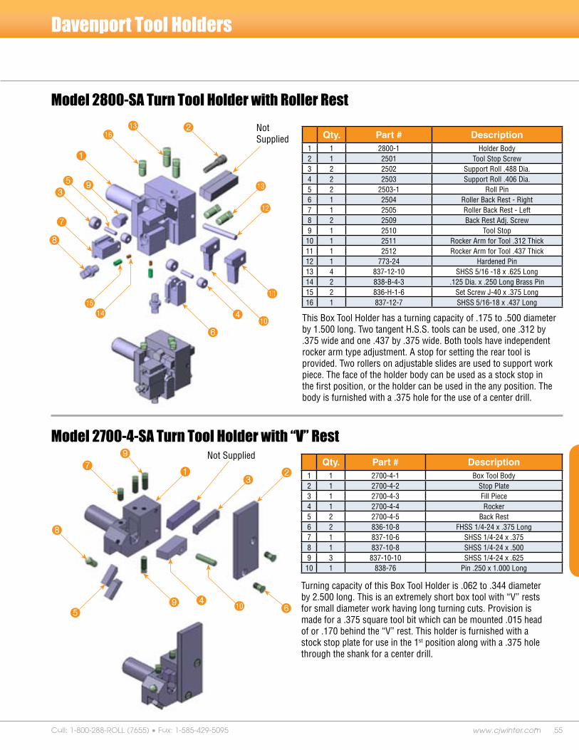
55www.cjwinter.comCall: 1-800-288-ROLL (7655) • Fax: 1-585-429-5095
Model 2700-4-SA Turn Tool Holder with “V” Rest
Turning capacity of this Box Tool Holder is .062 to .344 diameter by 2.500 long. This is an extremely short box tool with “V” rests for small diameter work having long turning cuts. Provision is made for a .375 square tool bit which can be mounted .015 head of or .170 behind the “V” rest. This holder is furnished with a stock stop plate for use in the 1st position along with a .375 hole through the shank for a center drill.
Qty. Part # Description1 1 2700-4-1 Box Tool Body2 1 2700-4-2 Stop Plate3 1 2700-4-3 Fill Piece4 1 2700-4-4 Rocker5 2 2700-4-5 Back Rest6 2 836-10-8 FHSS 1/4-24 x .375 Long7 1 837-10-6 SHSS 1/4-24 x .3758 1 837-10-8 SHSS 1/4-24 x .5009 3 837-10-10 SHSS 1/4-24 x .62510 1 838-76 Pin .250 x 1.000 Long
Model 2800-SA Turn Tool Holder with Roller Rest
This Box Tool Holder has a turning capacity of .175 to .500 diameter by 1.500 long. Two tangent H.S.S. tools can be used, one .312 by .375 wide and one .437 by .375 wide. Both tools have independent rocker arm type adjustment. A stop for setting the rear tool is provided. Two rollers on adjustable slides are used to support work piece. The face of the holder body can be used as a stock stop in the first position, or the holder can be used in the any position. The body is furnished with a .375 hole for the use of a center drill.
Qty. Part # Description1 1 2800-1 Holder Body2 1 2501 Tool Stop Screw3 2 2502 Support Roll .488 Dia.4 2 2503 Support Roll .406 Dia.5 2 2503-1 Roll Pin6 1 2504 Roller Back Rest - Right7 1 2505 Roller Back Rest - Left8 2 2509 Back Rest Adj. Screw9 1 2510 Tool Stop10 1 2511 Rocker Arm for Tool .312 Thick11 1 2512 Rocker Arm for Tool .437 Thick12 1 773-24 Hardened Pin13 4 837-12-10 SHSS 5/16 -18 x .625 Long14 2 838-B-4-3 .125 Dia. x .250 Long Brass Pin15 2 836-H-1-6 Set Screw J-40 x .375 Long16 1 837-12-7 SHSS 5/16-18 x .437 Long
9
bn
Davenport Tool Holders
bq
1
2
935
7
8
bpbo
6
4
bl
bk
bn
bm
79
8
5 6bk4
13
2
Not Supplied
Not Supplied

56 Your Formula for Success
Model 2794-2-SA Tool Setting Gage
Setting Gage is used to get tools in position. Gage dimensions are ground special per machine.
Qty. Part # Description1 1 2794-2 Gage Body, Long2 1 2794-2-1 Setting Gage Block3 1 834-10-8 Slot Head Screw 1/4-24 x .500
2
1
3
Davenport Tool Holders
Model 3154-8-SA 2nd & 3rd Pos. Mounting Block Assembly
This mounting block is used in the 2nd and 3rd positions for the 3264-20-SA Dovetail Skive Tool Holder and earlier models of the Davenport Dovetail Size Tool Holder. The mounting block is ported to bring coolant directly to the tool’s cutting edge.
Qty. Part # Description1 1 3154-8 2nd & 3rd Pos. Mounting Block2 1 3154-10 T Bolt, Short3 2 3154-11 Flat Key4 1 3154-13 Short Hex Nut 3/8-165 1 3154-14 Tool Adj. Screw6 2 3154-16 Nylon Plug7 1 P-89 Flex Hose8 1 P-89-1 Adapter9 1 682-3-A Clamp Ring10 1 682-3-B Threaded Clamp11 1 792-2 Front Tool Post Bolt12 2 834-A-14-12 SHCS 3/8-16 x .750 Long13 1 835-14-32 HHCS 3/8-16 x 2.000 Long14 4 836-4-6-4 FHCS #8-32 x .250 Long15 2 836-A-11-10 HSSS 1/4-28 x .625 Long16 1 840-14 Hex Nut 3/8-1617 1 MBLA-196-15-6 .250 Street Elbow
9
bkbq
bm
bl
bo2
4
35
8
bn
1 bp
br 7
6
6

57www.cjwinter.comCall: 1-800-288-ROLL (7655) • Fax: 1-585-429-5095
Shave Tool Holders
The high quality construction is consistent with the quality of our other Davenport tooling. Close tolerances allow for easy adjustments and reduce chatter on the work piece. The operator friendly design is constructed to be more versatile than other shave tools that are now available.
This tool contains solid carbide roll pins and high-speed steel rollers. Special brackets for the rollers are available to allow for positioning directly over the diameter you wish to shave.
Model 108 Shave Tool HolderThe premium quality hardened match ground 109 Dovetail Shave Tool Holder has superior rigidity and size control up to 1.058 diameter range, substantially reducing chatter in the work piece.
Model 109 Shave Tool Holder

58 Your Formula for Success
Features• .500 or .625 dovetail tooling can be accommodated with
our reversible clamp mechanism.• Reduced height by at least .500 over the Model 108 and
other shave tools. - Increased clearance between 2nd and 3rd positions
• Clamping dovetail on roll holder brackets. - Increased rigidity over boxway slide on 108
• Running dovetail with expansion gib. - Increased rigidity reduces chatter
• “High-performance coatings” Same as CJWinter 132 Reversible Slide. - Increased wear life for running surfaces.
• Micro Taper Adjust Mechanism – Patent Pending .0001-inch change in diameter for every “click” on taper adjust screw.
• Quick-Change Adapter Plate. - Full width adapter plate never needs to be removed - Locking expansion gib - Fine “In/Out” adjustment - Repeatability of location
• Modular mounting configurations are designed specifically for a Davenport Machine. Mounts to 1st, 2nd, 3rd, and 4th positions.
• Standard size 1-inch shank fits .75 diameter machines such as lathes, mills, Davenports, and many others.
• Two roll holder brackets accommodate entire range of diameters for shave tool and dovetail locking clamp allows added rigidity over boxway slides.
Micro Taper Adjust Mechanism – Patent Pending
Davenport Model 111 Shave Tool
• 2 roll brackets versus 6 on 108
• Pins and Rollers same as 108
• 111 Shave Tool will fit any 108 Tool Blocks
• Gives benefits of increased rigidity, reduced chatter, and longer wear life
• 108 Shave Tool will fit any 111 Tool Blocks
• Gives benefits of micro taper adjust and quick change
Comparison for model 108 Users:
The Model 111 Shave Tool has been engineered by CJWinter for a single purpose: to assure outstanding quality in every piece you shave. With a new lower profile than its predecessor, the Model 108 Shave Tool, the Model 111 allows for increased clearance between the 2nd and 3rd positions. It is also far superior to competitive shave tools in rigidity and tool life.
.375 S.C.to Body
.435 S.C.to Roll Pin
Recomended 'H':H = .812 - (D/2)
'H'(Shave Tool Height)
.812Tooling Constant
(1/2" or 5/8")'W'
.750Roller
BRACKET
.625 &
1.00"SHANK
'D'(WORK PIECE DIA.)RANGE -.060 to .843

59www.cjwinter.comCall: 1-800-288-ROLL (7655) • Fax: 1-585-429-5095
This slide is made of the same quality and has all the features of our 130-EG Series Tool Slide, except the 131-EG comes with an independent stop feature.
With independent stop for Davenport Automatics
131-EG Series 4th Position Adjustable Tool Slide
Item Part # Qty. Description
1 131EG 1 Adjustable Tool Slide
2 130052 1 Adj. Tool Block for Independent Stop
3 130000EG 1 Slide/Base (Match Assy.)
4 130005 2 Spring Anchor
5 130008 1 Segment Plate
6 130009 1 Segment Worm
7 130058 1 Expansion Gib
8 130904 1 Link Assy. (Components: 130013/014&015)
9 130013 1 Link Nut
10 130014 1 Link L.H.
11 130015 1 Link R.H.
12 130016 1 Stop Block
13 130017 1 Link Pin
14 130018 1 Stop Pin
15 130019 1 Brass Tip
16 130021 2 SHCS 5/16-18 x .750
17 130022 1 SQHSS 5/16-18 x 1.500 Cup Pt.
18 130023 1 SSS 1/4-20 x .375 Cup Pt.
19 130024 1 SSS 1/4-20 x .750 Cup Pt.
20 130025 2 SSS 1/4- 20 x .250 Cup Pt.
21 130028 1 FHCS #10-32 x .375
22 130060 2 SHCS #4-40 x 1.000
23 130062 1 Insert: Threaded (thinwall) 9/16-12 x 7/16-14
24 130031 2 Pin, Segment Plate
25 130039 1 Adjustment Screw
26 838-6 1 Pin: Dowel .250 x .625
27 836-A-3 1 SSS 5/16-18 x .625 Cup Pt.
28 130046 2 SHCS 5/16-24 x .625
29 130047 2 SHCS 5/16-24 x 1.000
30 834-14-16 4 FHCS 3/8-16 x 1.000
31 130053 1 Independent Stop
32 130054 1 SSS 1/4-20-x .500
33 740-3 1 Adj. Slide Stop Screw 1 5/8
co
cqclcn cr 6 ct
4
br
bp
bmbs
btck4ckcs
dn dl
cp
2bn bl 9bk
8
bq
bo7cm
3
bp
dm
5
1
* Item FHCS 3/8-16 x 1.000 Not Shown.dk
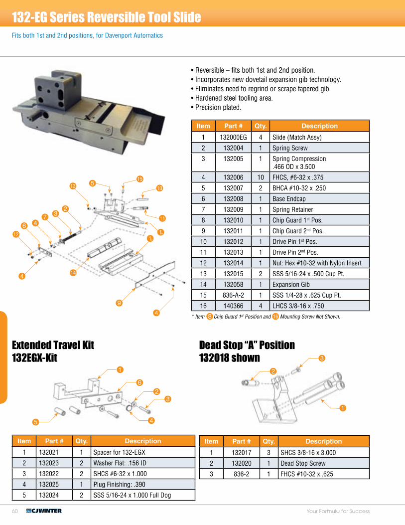
60 Your Formula for Success
• Reversible – fits both 1st and 2nd position. • Incorporates new dovetail expansion gib technology. • Eliminates need to regrind or scrape tapered gib. • Hardened steel tooling area. • Precision plated.
Extended Travel Kit132EGX-Kit
Fits both 1st and 2nd positions, for Davenport Automatics
132-EG Series Reversible Tool Slide
Item Part # Qty. Description
1 132000EG 4 Slide (Match Assy)
2 132004 1 Spring Screw
3 132005 1 Spring Compression .466 OD x 3.500
4 132006 10 FHCS, #6-32 x .375
5 132007 2 BHCA #10-32 x .250
6 132008 1 Base Endcap
7 132009 1 Spring Retainer
8 132010 1 Chip Guard 1st Pos.
9 132011 1 Chip Guard 2nd Pos.
10 132012 1 Drive Pin 1st Pos.
11 132013 1 Drive Pin 2nd Pos.
12 132014 1 Nut: Hex #10-32 with Nylon Insert
13 132015 2 SSS 5/16-24 x .500 Cup Pt.
14 132058 1 Expansion Gib
15 836-A-2 1 SSS 1/4-28 x .625 Cup Pt.
16 140366 4 LHCS 3/8-16 x .750
Item Part # Qty. Description
1 132021 1 Spacer for 132-EGX
2 132023 2 Washer Flat: .156 ID
3 132022 2 SHCS #6-32 x 1.000
4 132025 1 Plug Finishing: .390
5 132024 2 SSS 5/16-24 x 1.000 Full Dog
* Item Chip Guard 1st Position and Mounting Screw Not Shown.
9
4
bm6 4
73
2
bo
1b
1a
bn 5bp
bk
bl
23
45
1
6
Item Part # Qty. Description
1 132017 3 SHCS 3/8-16 x 3.000
2 132020 1 Dead Stop Screw
3 836-2 1 FHCS #10-32 x .625
2
3
1
Dead Stop “A” Position132018 shown
48 bq

61www.cjwinter.comCall: 1-800-288-ROLL (7655) • Fax: 1-585-429-5095
CJWinter® Machine Technologies introduces a new series of American-made end rolling attachments for thread rolling applications. The CJWinter ER-SERIES end rolling attachments features innovative design that provides high rigidity for longer tool life and better quality threads, as well as superior thread roll protection.
The CJWinter ER-SERIES Features One piece front plate enclosures:- Provides superior roll protection from debris- Have fewer parts and increased rigidity
Carbide bushings are standard equipment on all attachments.
Engraved scale allows thread pitch diameter adjustments on the machine.
High-strength construction for longer tool life. - Extensive use of tool steel and custom heat treat on wear surfaces- Special coating on all wear surfaces for smoother operation and extended life- Cheaper operating costs = More profits for you at no extra charge - Carbide Bushings replace cumbersome needle bearings
Compact sizes fit virtually any type of machine including CNC turning centers, Swiss, Multi-Spindle and many others.
Shank Sizes (custom shank sizes are also available). - ER 189: .625” & .750” Standard Shank- ER 190: .750” Standard Shank- ER 191: 1” Standard Shank
End Rolling Attachments
For CNC Threading ApplicationsFor CNC Threading Applications
Made in the USA

62 Your Formula for Success
Model 189
#.## #.##Standard (in)
Metric (mm)
1.79 47.47
2.95 74.93
3.15 80.01
0.625 15.88Ø
1.58 40.13Ø
0.47 11.94Ø
0.75 19.05
1.50 38.10
4.56 115.82
4.88 123.95
Ø
2.50 63.50Ø0.67 17.02Ø
1.00 25.40
2.15 54.61
5.93 150.62
6.35 161.29
Ø
Model 191
3.47 88.14Ø0.95 24.13Ø
ER Series End Rolling Attachments for CNC & Other Threading Applications
Model 190
Fits Swiss Style Machines!

6�www.cjwinter.comCall: 1-800-288-ROLL (7655) • Fax: 1-585-429-5095
Key: Roll Type Delivery Stock Shipsameday Standard 1-5days
*Callforspecialnon-standardthreadrolldeliverytimes
MetricISOThreads
SizeInStock(Y/N)
.6L1L2LM3.5x0.6M4x0.75M4x0.7M4x0.5M4.5x0.75M4.5x0.5M5x0.9M5x0.8M5x0.75M5.5x0.9M5.5x0.75M6x1
UnifiedThreads
SizeInStock(Y/N)
.6L1L2L#6-40#8-32#8-36#10-24#10-32#12-24#12-28#12-321/4-201/4-281/4-32
UnifiedThreads
SizeInStock(Y/N)
.6L1L2L1/4-201/4-241/4-271/4-281/4-325/16-185/16-205/16-245/16-283/8-163/8-183/8-203/8-247/16-147/16-167/16-187/16-207/16-27
MetricISOThreads
SizeInStock(Y/N)
.6L1L2LM6x1M6x0.75M7x1M7x0.75M8x1.25M8x1M9x1.25M9x1M10x1.5M10x1.25M10x1
MetricISOThreads
SizeInStock(Y/N)
.6L1L2LM8x1.25M8x1M8x0.75M9x1.25M9x1M10x1.5M10x1.25M11x1.5M12x1.75M12x1.5M12x1.25M13x1.5M14x2M14x1.5M15x1.5M16x2M16x1.25
UnifiedThreads
SizeInStock(Y/N)
.6L1L2L5/16-185/16-245/16-283/8-163/8-247/16-147/16-167/16-201/2-131/2-161/2-181/2-209/16-129/16-149/16-169/16-185/8-115/8-125/8-165/8-18
ER Series & 234-SA Series Consult factory for specific application information
189 ER Series Thread Rolls
190 ER Series Thread Rolls
191 ER Series Thread Rolls
Model 234-SA Series Rotary Radial Attachment
• Fast and easy set up; this compact 4.0 height from spindle to nose attachment has close to shoulder rolling within .125 depending on the application.
• In most cases the Model 234 can roll threads behind a shoulder or on both sides of a shoulder at the same time.
• Complete control over roll infeed and RPM.
• Timing compensator reduces or eliminates most threading problems.
Model 234-SA for Hydromat® Machines
234-SA Series Thread Roll Capacities:
#0-80 to 3/4-32
1/16-27 NPT to 3/8-18 NPT
M1.4 x 0.3 to M18 x 2.5
5.000

64 Your Formula for Success
Bent Shank Taps For Davenport Automatics
Tolerance ranges are as follows:• H1 Basic to Basic plus .0005”• H2 Basic plus .0005” to Basic plus .001”• H3 Basic plus .0001” to Basic plus .0015”• H4 Basic plus .0015” to Basic plus .002”• H5 Basic plus .002” to Basic plus .0025”• H6 Basic plus .0025” to Basic plus .003”• H7 Basic plus .003” to Basic plus .0035”
Please supply print of bent shank tap required.
Ground thread taps above basic pitch diameter tolerance are identified by letter “H”.
Refer to factory for special thread sizes, pitch diameters not listed and taps or nibs supplied by customer. If shank diameter is different than shown, please specify size required.
ISO Metric Bent Shank Taps – consult factory when ordering.
* 3.5 available for special applications.** 32 available for extended bed machines.
Consult factory for specific application information
A full range of links, from 31/32 to 1 9/16 are available in 1/64 increments. These will accommodate most thread sizes and number of starts for Davenport attachments.
Links & Link Blanks For Davenport Scissors Type Attachments
Nominal Size
Threads Per InchPitch Diameter
No. Flutes
Approx. Shank DiameterNC NF
#2#2#2
5656
-------
----------64
H2H1H2
222
0.0580.058-----
----------
0.058
#3 #3 #3
48----------
-----5656
H2H2H1
222
0.066----------
-----0.0690.069
#4 #4 #4
4040
-----
----------48
H2H1H2
222
0.0780.078-----
----------
0.078
#5 #5 #5
4040
-----
----------44
H2H1H2
222
0.0890.089-----
----------
0.089
#6 #6 #6
3232
-----
----------40
H2, H3H1, H7
H2
222
0.0930.093-----
----------
0.100
#8 #8 #8
3232
-----
----------36
H2, H3H1, H7
H2
222
0.1200.120-----
----------
0.125
#10 #10 #10 #10 #10
242424
----------
---------------3232
H3H2
H1, H7H2, H3
H7
22222
0.1350.1350.135----------
---------------
0.1390.139
#12 24 28 H3 2 0.166 0.166
1/4 1/4 1/4 1/4
2020
----------
----------2828
H1, H2, H5H3
H1, H2, H3, H4H2, H4
2223
0.1840.184----------
----------
0.1970.197
5/16 5/16 5/16 5/16 5/16 5/16 5/16
18181818
---------------
--------------------242424
H3H2, H5
H1H3, H5
H3H1, H2, H4
H4
2223223
0.2420.2420.2420.242---------------
--------------------
0.2500.2500.250
3/8 3/8 3/8 3/8 3/8
161616
----------
---------------2424
H3H2
H1, H5H3
H1, H2, H4
33333
0.2810.2810.281----------
---------------
0.3120.312
Custom Link Sizes
Thread Size Link Size Thread Size Link Size Thread Size Link Size
4-40 1 13/32 1/4-28 1 3/8 5/8-18 1 3/16
4-48 1 7/16 1/4-32 1 11/32 5/8-24 1 1/8
5-40 1 3/8 5/16-18 1 23/64 5/8-32 1 3/32
5-44 1 11/32 5/16-24 1 1/4 3/4-20 1 15/32
6-32 1 13/32 5/16-32 1 15/32 M3.5 x 0.6 1 3/8
6-40 1 13/32 3/8-16 1 11/32 M4.0 x 0.7 1 29/64
8-32 1 7/16 3/8-24 1 13/64 M5.0 x 0.8 1 13/32
8-36 1 3/8 3/8-32 1 9/64 M6.0 x 1.0 1 5/16
10-24 1 13/32 7/16-20 1 11/32 M8.0 x 1.25 1 9/32
10-28 1 1/2 1/2-13 1 7/32 M10.0 x 1.5 1 17/64
10-32 1 29/64 1/2-20 1 3/32 M12.0 x 1.75 1 19/64
12-24 1 1/2 1/2-24 1 1/32 1/16-27NPT/NPTF 1 1/4
12-28 1 7/16 1/2-28 1 1/64 1/8-27 NPT/NPTF 1 1/16
12-32 1 13/32 9/16-12 1 15/32 1/4-18 NPT/NPTF 31/32
12-36 1 3/8 9/18-18 1 3/8 3/8-18 NPT/NPTF 1 1/32
1/4-20 1 1/2 9/16-24 1 5/16 1/2-14 NPT/NPTF 1 13/32
1/4-24 1 7/16 5/8-11 1 5/16

65www.cjwinter.comCall: 1-800-288-ROLL (7655) • Fax: 1-585-429-5095
Thread Roll Trouble Shooting Guide
Problem Cause Solution
Poor Thread Form
1. Work bending during rolling.2. Rolls not in match.3. Too many work revolutions. 4. Centerline of rolls not parallel with center
line of work.
1. Support part during rolling. 2. Re-synchronize rolls.3. Increase rate of roll penetration. 4. Check slide for alignment.
Thread Filled Out in Center, But Not Towards Ends, or Vice Versa
1. Blank with varying diameter from end to end.
2. Center line of rolls not parallel with center line of work.
1. Check blank for taper or shave tool not reaching center.
2. Check slide for alignment.
Poor Finish on Threads
1. Overfilling rolls.2. Rolls not synchronized. 3. Material accumulated in threads on rolls.
4. Material not ductile enough for cold-working.
5. Chips, from other operations, between rolls and work.
6. Correspondingly poor finish on rolls.7. Rolls that are worn or broken.
1. Check blank diameter oversize. 2. Re-synchronize thread rolls.3. Replace rolls if material cannot be
removed.4. Change material.
5. Make sure a good jet of clean oil is reaching rolling position.
6. Replace rolls.7. Replace rolls.
Split Thread-Axially 1. Seamy stock.2. Mark from shave tool or hollow mill.
1. Change Stock. 2. Regrind tooling.
Crests Not Filled Out (Many users do not consider this a serious objection and by allowing their threads to pass with crests not filled out, overloading of rolls is avoided and roll life is prolonged.)
1. Blank too small.2. Thread on roll too deep.
1. Increase blank diameter. 2. Replace rolls with rolls of correct depth
for job. Note: Special truncated rolls are available from CJWinter.
Scuffed Crests
1. Attachment not retracting fast enough. 2. Rolls and gear train binding.
3. Rolling not on center line of work. 4. Material accumulated in threads on rolls.
1. Increase speed of roll retraction. 2. Check gear train, remove any foreign
matter.3. Reset slide with gauge. 4. Check oil jet flowing on rolling position.
Hollow Work, Hole Closed In
1. Insufficient wall thickness. 2. Improper supporting mandrel.3. Feed rate too high, causing too rapid
penetration.
1. Drill later in cycle. 2. Use proper supporting mandrel.3. Slow down penetration rate.
Hollow Work, Hole Enlarged
1. Material extruding due to insufficient wall thickness.
2. Supporting mandrel too tight. 3. Blank too large on major diameter. 4. Feed rate too high causing too rapid
penetration.
1. Use smaller drill before rolling.
2. Reduce mandrel diameter. 3. Reduce blank diameter. 4. Slow down rate of penetration.
Hollow Work, Out of Round
1. Material deforming due to insufficient wall thickness.
2. Feed rate too high causing too rapid penetration.
3. Too few work revolutions.
1. Drill later in cycle.
2. Slow down rate of penetration.
3. Slow down rate of penetration.
Hollow Work, Tapered Threads
1. Uneven and insufficient wall thickness. 2. Improper mandrel not giving support
where needed. 3. Feed rate too high causing too rapid
penetration. 4. Taper of rolls not great enough to
compensate for tendency of work to taper.
1. Drill later in cycle. 2. Check mandrel for size with hole.
3. Slow down rate of penetration.
4. Use correct rolls for job.

66 Your Formula for Success
Thread Roll Trouble Shooting GuideProblem Cause Solution
Slivers or Flakes on Threads
1. Rolls not in match. 2. Center line of rolls not parallel with center
line of work. 3. Loose or worn cross slide or adapter.
4. Overfilling rolls. 5. Material not adaptable to cold-working.
6. Rough finish on blank. 7. Seamy stock.8. Feed rate too slow, causing rolls to slip on
work.9. Incorrect roll diameter.
1. Re-synchronize rolls. 2. Check slide for alignment.
3. Check slide gib and spring. Tighten adapter if used.
4. Reduce blank diameter. 5. Change material. Check with material
supplier. 6. Regrind tooling. 7. Not suitable for roll threading.8. Increase rate of penetration.
9. Use correct rolls for job.
Drunken Threads
1. Rolls not in match. 2. Center line of rolls not parallel with center
line of work. 3. Inaccurate rolls.4. Work bending during rolling.
1. Re-synchronize rolls. 2. Check slide for alignment.
3. Replace rolls. 4. Support part during rolling operation or
slow down penetration rate if possible.
Offsize Threads:1. Pitch diameter and major diameter, both
oversize. 2. Pitch diameter oversize, major diameter
correct size. 3. Pitch diameter oversize, major diameter
undersize. 4. Pitch diameter correct size, major
diameter oversize.5. Pitch diameter correct size, major
diameter undersize.6. Pitch diameter undersize, major diameter
oversize. 7. Pitch diameter undersize, major diameter
correct size. 8. Pitch diameter and major diameter both
undersize.
1. Oversize blanks.
2. Oversize blanks. If finished thread is full, thread on roll is too shallow.
3. Insufficient penetration on rolls. If finished thread is full, thread on rolls is too shallow.
4. Blank too large. Thread on roll deeper than necessary.
5. Blank too small. If finished thread is full, thread on roll is too shallow.
6. Excessive penetration. Thread on roll deeper than necessary.
7. Blank too small. Thread on roll deeper than necessary.
8. Blank too small.
1. Reduce blank diameter.
2. Use correct rolls for job.
3. Increase roll penetration.
4. Reduce blank diameter.
5. Increase blank diameter. Use correct rolls for job.
6. Reduce roll penetration. Use correct rolls for job.
7. Increase blank diameter. Use correct rolls for job.
8. Increase blank diameter.
Out of Round Threads
1. Out of round blank.
2. Center line of rolls not parallel with center line of work.
3. Feed rate too high. 4. Insufficient work revolutions. 5. Material not ductile enough for cold
working. 6. Attachment not on center line of work.
1. Shave tool not reaching center or not cleaning up rough form diameter.
2. Check slide for alignment
3. Reduce rate of penetration 4. Reduce rate of penetration 5. Change material. Check with supplier.
6. Reset cross slide with gauge.
Tapered Threads:1. Pitch diameter straight. Major diameter
tapered and not filled out on small end. 2. Pitch diameter and major diameter both
tapered same way.3. Pitch diameter and major diameter tapered
in opposite directions and thread not filled out on end with small major diameter.
1. Tapered blank.
2. Tapered blank.
3. Rolls not penetrating deep enough on edge with large pitch diameter and small major diameter, or work bending during rolling.
1. Straighten blank.
2. Straighten blank.
3. Support part during rolling. Part deflecting out of contact with center of rolls.
Thread with Expanded Lead1. Expanded lead in rolls.2. Material extruding on short length of
blank.
1. Use correct rolls. 2. Use longer blank and remove excess in
another position.
Thread with Contracted Lead 1. Contracted lead in rolls. 1. Use correct rolls for job.

67www.cjwinter.comCall: 1-800-288-ROLL (7655) • Fax: 1-585-429-5095
Notes

68 Your Formula for Success
Notes

ENDROLLING PNEUMATIC THREAD
ROLLS TANGENTIAL TOOL HOLDERS AND SLIDES
167 Ames Street • Rochester, NY 14611 USA1-800-288-ROLL (7655) • Phone (585) 429-5000 • FAX (585) 429-5095
E-mail: [email protected] • www.cjwinter.com
Mission StatementCJWinter Machine Technologies manufactures the premier line of thread rolling attachments, thread rolls, specialty dies and tooling for Davenport and CNC machines. CJWinter has proven that speedy delivery,
flawless quality and competitive prices can all be delivered simultaneously. Our team of dedicated engineers focuses on solving every customer’s thread rolling and metal forming challenges. Our
specialty is providing superior products in the industries shortest lead time.
Corporate Headquarters:Rochester, NY
CJWINTER0209/2500