your expert for vibration insulation · dynamic forces (injection moulding machines, stamping...
TRANSCRIPT

GeneralCatalogue
Your Expert forVibration Insulation and Machine Leveling Technology

Bilz Vibration Technology AG is based in Leonberg, Germany. Bilz has specialized in machine mounting technology with a focus on vibration isolation. Bilz is Europe‘s leading anti-vibration specialists supplying products and services to machine and equipment manufacturers as well as automobile industry worldwide. Vibration isolation is always an issue when it comes to precision machining or measurement. 45 years of experience in the field of vibration technology enables Bilz to offer a wide range of solutions. These solutions include: simple isolation pads, rubber & membrane air springs, mechanical & electro-pneumatic level control systems & active vibration cancellation systems, special machine foundations and vibration measurement and analysis
Machine House (India) Pvt Ltd, based in Nashik India, is associated with Bilz for more than 2 decades, mainly for manufacturing (exports to Bilz, Germany) and marketing & sales in India. Extensive technical support from Bilz combined with rich manufacturing and marketing experience has established Machine House as a pioneer in the field of high quality anti vibration solutions. Powered by a highly trained sales and design team in Nashik along with an established dealer network in all major industrial cities in India, Machine House is equipped to undertake critical vibration isolation projects dealing with precision machining and measurements.'Effective and cost efficient solutions for nearly every problem caused by vibration', A claim that Bilz Vibration Technology and Machine House (India) Pvt Ltd meet very successfully every day worldwide !
When solutions are requiredquality makes the difference.
Your benefits from Bilz technology and know-how
n Optimum vibration and structure-borne noise isolationn Effective protection of people, environment and buildingsn Quality improvements through reduced manufacturing
tolerances and increased manufacturing precisionn Increased production throughput by shortening cycle
times in productionn Cost reductions through simplified and flexible machine
installationn Quality and safety through compliance with the latest
standards, directives and guidelinesn DIN ISO 9001n EC Machinery Directiven EC Low Voltage Directiven EC EMC Directive
Content
General
Insulation pads
Leveling Mounts
Precision Leveling Wedges
®FAEBI Rubber Air Springs
®BiAir Membrane Air Springs
Level Control
Vibration Isolation Tables
Indirect Isolation
Vibration Measurement
1 - 2
3 - 8
9 - 13
14 - 20
21 - 27
28 - 30
31 - 32
33 - 37
38 - 48
49 - 50

1

Vibration control matching
Insulation of periodically excited vibrationsThe effect of vibration insulation depends mainly on the ratio of the disturbance frequency or excitation frequency to the natural frequency of the insulator (matching ratio), and its damping.With source insulation the excitation frequency is the machinespeed or stroke rates, with receiver insulation disturbing ground vibrations. Generally it can be said that the lower the natural frequency of the insulator the better the efficiency of the insulator, i.e., the larger the ratio of disturbing frequency is compared to the natural frequency. The resulting graph showsthat an isolating effect only occurs when the value of the harmo- nizing ratio is greater than � 2 At smaller values an amplification(resonance magnification) of the disturbing force may also occur.
Transmission factor V sof the vibration insulationwithout damping:
The transmission factortaking into account thedamping ratio D is:
VP
Disturbing or exciting frequency
Natural frequency of the insulator
Matching ratio
Usually a matching ratio of between 3 and 4 is striven for, whereby 3 is considered the technical lower limit and 4 the economic upper limit. A matching ratio larger than 4 cannot normally be justified from the economic perspective because the material expense would increase above average compared to the degree of insulation
2
IMPACT INSULATION
Matching ratio Ƞ
Impact insulationThe physical properties of impacts are their duration, direction and magnitude. The object of impact insulation is to change the forcing frequency consisting of a high kick into an impulse of longer duration accompanied by small residual forces. Different from periodically excited vibrations, the system provided with springs vibrates in the excited natural frequency of the insulated system, not according to its number of strokes. The residual forces transferred via the insulators become increasingly smaller, the longer the natural vibration period lasts and therefore the smaller the natural frequency of the system sitting on a foundation equipped with springs.So, the efficiency factor of an impact insulation is:
= natural frequency of the system rigidly secured to the ground= natural frequency of the system when placed on insulators containing springs.
be

3
Insulation padsBilz insulation pads have been used successfully for many years in a variety of indu-stries as an economical solution in the fight against problems caused by vibration andstructure-borne noise.Made from a precisely defined combination of nitrile rubber and cork particlesembedded in a composite of cotton fibres, the physical and mechanical properties ofthis high-quality composite material meet all of the current requirements for variousindustrial applications depending on type of pad. Very good damping properties ensureoptimum deflection and level consistency both under static and under dynamicloading.The material composition used ensures secure anti-slip protection on conventionalindustrial floors. It has high resistance properties particularly to modern coolinglubricants.

4
FOUR POSSIBLE OPTIONS FOR THE USE OF INSULATION PADS FOR MACHINE INSTALLATION
Avoiding vibration and structure-borne noise problems has alwaysbeen in our focus during the development of Bilz insulating pads.As, depending on the type of machine, the requirements can bevery different because of the dynamic particularities, there arenumerous different types of pads available for almost any vibra-tion problem. Especially noteworthy are the excellent compre-ssion set values of our insulation pads. This property is particularlyimportant in vibration-isolated mounting of modern machinesbecause the geometric accuracy must remain unchanged andstable for years.
Structure-borne noiseEffective noise insulation
Virtually unlimited service life with adherence to load values. Nopermanent changes in shape.
Aging resistant
Chemical resistanceExceptionally good resistance to oils, grease, acids and coolingemulsions used in industry.
Temperature resistance-20 °C to +120 °C
Damping propertiesVery high degree of damping of up to 30 %
Stable connection to themachine bed using bolt-oninstallation fittings thatremain in place when themachine is lifted. Specificallyfor machines with highdynamic forces (injectionmoulding machines,stamping equipment, etc.).
Free-standing machinefoundations using Bilz insula-tion pads with low demandson alignment. The unevenfloor is compensated for withpads, etc. The arrangementof the pads is usually apattern of points, not overthe full surface. Number andsize of the required insula-tion pads is given by theweight of the machine andthe existing support surface.
Bolt-through groundanchoring using insulationpads and insulation washers.The use of insulationwashers prevents vibrationsbeing transmitted throughthe bolt.
Highly effective shock andvibration insulation by Bilzinsulation pad sets.Different Bilz pads arecombined into pad setsoffering significantlyimproved insulation.
Bilz insulation pads are resistant to the following substances:
Lubricants
Greases for plain and roller bearings, gear greases
Synthetic lubricantsPolyalkylene, carboxylic acid esters, antifreezeCombustibles and fuelsPetrol, diesel fuel, heating oil, aviation fuel, special fuels
Mineral oils
Fire resistant hydraulic fluidsOil-in-water emulsions, water-in-oil emulsions, aqueous polymersolutions
Common water-miscible cooling lubricants, ATF (Automatic Trans-mission Fluid), cooling lubricants, water-miscible anti corrosiveoils, slideway oils, compressed air oils, lubricating oils, heattransfer oils, filter oils, rolling oils, automotive gear oils, brakefluids based on mineral oil
Cleaning agentsHydro-chlorofluorocarbons, benzene, cold cleanerCleaning agent (aqueous solutions)Washing and cleaning agents, wetting agents, dilute acids, dilutealkalis, salt solutions
1 2 3 4

5

Type Heightmm
Coefficientof friction
0.8B5 5-16 25
(3)
Type Heightmm
Coefficientof friction
0.8B50 5-20 25
(3)
Type Heightmm
Coefficientof friction
0.8B32 2-8 25
(3)
PAD TYPE B50
PAD TYPE B32
For machines subject to veryhighly dynamic disturbingforce, such as presses,punches, shears, etc.With a profile for compen-sating uneven floors.
For machines subject tovery highly dynamicdisturbing force, such aspresses, punches, shears,etc.
Soft variant without aprofile.Excellent insulation effectfor mid-sized presses,punches, etc.
6
PAD TYPE B5 DYNAMIC NATURAL FREQUENCY
DYNAMIC NATURAL FREQUENCY
DYNAMIC NATURAL FREQUENCY
Load2Kg/cm
Load2Kg/cm
Load2Kg/cm
2Load [Kg/cm ]
2Load [Kg/cm ]
2Load [Kg/cm ]
0 5 10 15 20
0 5 10 15 20 25
0 2 4 6 8 10

Type Heightmm
Coefficientof friction
0.8B32W 3.5-7 25
(3)
PAD TYPE B30W DYNAMIC NATURAL FREQUENCY
Soft variant without aprofile. Particularly suitablefor effective insulationwhen installing on upperfloors.
Type Heightmm
Coefficientof friction
0.8B30 2-8 18
(3)
Very soft variant for optimuminsulation through low-frequency matching, such asfor measuring machines andinspection machines, scalesand microscopes
Type Heightmm
Coefficientof friction
0.8B30W 0.5-4 18
(3)
7
Right to make technical changes is reserved.
Very soft variant, compa-rable with B30, but withimproved insulation effect.
PAD TYPE B32W DYNAMIC NATURAL FREQUENCY
PAD TYPE B30 DYNAMIC NATURAL FREQUENCY
(2)
Load2Kg/cm
Load2Kg/cm
Load2Kg/cm
2Load [Kg/cm ]
2Load [Kg/cm ]
2Load [Kg/cm ]
0 2 4 6 8 10
0 2 4 6 8 10
0 1 2 3 4 5

8

Levelling elementsBilz levelling elements are used for vibration and structure-borne noise insulatedmachine installation. The maintenance-free machine feet guarantee the simple andprecise levelling of machines and are available in many versatile designs.The sizes and insulation pads are selected according to the application and load. The range of levelling can be adapted depending on the selected bolt length and theindividual requirements.
General information
The type of insulation pads used can be found in the type description,e.g. BNSH 80/50 is equipped with B50, BNVS 50/30W with B30W etc.
The specified maximum load is composed of static and dynamic loading of the machine.The best insulation effect is achieved at approximately 80-90 % of the specified maximum load.
Details on the properties of the insulation pads used can be found on pages
Permissible temperature range: -20 °C bis +120 °C
Please contact us if the size, colour, insulation pad mounting, or bolts that you are looking for are not listed. In addition to our standard solutions and colours we also carry numerous special solutions.We are always happy to offer our advice.
9

H
G
D
H
G
Ø D
G
Ø D
dH
C
EB
A
AL
BNSH BNSHA
10Right to make technical changes is reserved.
Series BNSH/BNSHARound, without/with bolt-on floor attachment.
Application : Specifically developed for the mounting of injection mouldingmachines, presses, punches etc. Optimum load distribution due to our provenpressure plate design. Very high horizontal stability over the entire levelling range.The BNSHA elements with bolt-on floor plate are particularly suitable for allmachines that tend to wander. The floor anchor is not used as a safeguard againsttipping.
BNSH / BNSHA
BNSHA BASE PLATE DIMENSION
Type
BNSHA 70BNSHA 80BNSHA 100BNSHA 120BNSHA 140BNSHA 160BNSHA 175BNSHA 200BNSHA 250
125140160180200220260300330
Lmm
TypeBNSH /BNSHA
70/480/4 100/4120/4140/4160/4175/4200/4250/4
Load Kg/pc
TypeBNSH /BNSHA
Load Kg/pc
HBNSH With B4 and B0
mm
HBNSHA With B4 and B0
mm
TypeBNSH /BNSHA
Load Kg/pc
TypeBNSH /BNSHA
Load Kg/pc
HBNSH WithB32 and B5
mm
HBNSHA WithB32 and B5
mm
O D
mm
AdjustmentRange
mm300450700100013751800215031004400
70/080/0 100/0120/0140/0160/0175/0200/0250/0
720940
1,4702,1002,8803,7504,5005,8009,000
25.0040.0045.0045.0045.0045.0050.0055.0055.00
29.0044.0049.0049.0049.0049.0054.0059.0059.00
70/3280/32 100/32120/32140/32160/32175/32200/32250/32
275425625900
1,2251,6001,9002,5003,900
70 / 580 /5 100/5120/5140/5160/5175/5200/5250/5
500800
1,1751,6502,3003,0003,6005,1007,300
40.0044.0049.0049.0049.0049.0056.0062.0064.00
44.0048.0053.0053.0053.0053.0060.0066.0068.00
8096
113133153175193229270
61212121212121212
Amm151515151515202020
Bmm7590110125150170185225265
Cmm105120140160180200230270300
Emm
88
11131616202020
dmm
555555888
BOLT DIMENSION
Type
BNSH / A 70BNSH / A 80BNSH / A 100BNSH / A 120BNSH / A 140BNSH / A 160BNSH / A 175BNSH / A 200BNSH / A 250
M10M12M16M16M16M20M20M24M30
ThreadG
Pitch
1.251.501.501.501.501.501.502.002.00

BNVSL
B
H
L
±3°
Type BNV / BNVS50/480/4 110/4115/4150/4200/4
Load Kg/pc
2004701200114018003700
Type BNV / BNVS50/080/0 110/0115/0150/0200/0
Load Kg/pc
4009502400228036007400
Type BNV / BNVS
50/30W80/30W 110/30W115/30W150/30W200/30W
Load Kg/pc
952305004507301500
Lmm
6085124163147264
Bmm
608512488147165
Hmm
With B4/B0212228293035
Hmm
With B30W242531323338
BNRS
H
Ø D
Ø D
±3°
BNV
BNVS
11
BNV / BNVS (SQUARE)
Series BNV / BNVS
Application: Proven and very effective plate element, preferably for lightto medium heavy machines with matching locating holes in the machinefeet. The BNV/BNVS elements are used where a rigid joint is required be-tween the machine and the fitting. Any unevenness or angular differencesin the floor up to ± 3° can be compensated for using the movable level-ling bolt.
Square, without/with flexible levelling bolt
BNRS
BNR
BNR / BNRSRound, without/with flexible levelling bolt
Application, Properties and bolts:See type BNR/BNRS
Right to make technical changes is reserved.
Type BNR / BNRS50/465/470/4 80/495/4110/4150/4175/4200/4250/4
Load Kg/pc
1703003604207009101700215031004400
Type BNR / BNRS50/065/070/0 80/095/0110/0150/0175/0200/0250/0
Load Kg/pc
340630720840120018203400410062008200
Type BNR / BNRS
50/30W65/30W70/30W 80/30W95/30W110/30W150/30W175/30W200/30W250/30W
Load Kg/pc
6012014016027535069085012001700
Dmm
60748587105121163190215253
Hmm
With B4/B021212525232932303037
Hmm
With B30W24242828263235333340
BNR / BNRS (ROUND)
BNR/BNRS are used in cases where a firm connection of the element to the machine is desirable. Angle difference are equalized by means of the movable leveling screw.

12
BNRV
BNRSV
Application: Food, luxury food, packaging, chemical and pharmaceuticalindustries as well as clean room applications.
Insulation pad properties: B4: Medium hard pad with good vibration and structure-borne noise insulation. Universal application.
B30W: Soft matching for a very good insulation effect, e.g. for grinding machines, test equipment, measuring machines, etc.
BR7: Anti-slip plate without vibration insulation.
BNRV / BNRSV
Series BNRV / BNRSV stainless-steel designRound, stainless-steel design, without/with flexible levelling bolt
BNRSV
Ø D
H
Ø D
±3°
Type BNRVBNRSV50/470/4110/4150/4
Load Kg/pc
1703609101700
Type BNRVBNRSV50/070/0110/0150/0
Load Kg/pc
34072018203400
Type BNRVBNRSV
50/30W 70/30W110/30W150/30W
Load Kg/pc
70140350690
Dmm
5476116156
Hmm
With B4/B023252729
Hmm
With B30W26283032
SERIES amt MM (round, steel with threaded rod)
Application: Cost-effective leveling mount for machines with high vertical and horizontal dynamic forces, adequatevibration and structure-borne noise isolation, pressure plate that can be precisely leveled for optimum weight distribution.The rubber mount is resistant to commercial acids, alkalis and lubricating oils.Threaded rods: Appropriate threaded rod each with a nut and washer included.
Type
MM 1MM 2MM 3MM 4
Max LoadKg/pc.
5001,1002,1004,000
ODmm
80120160200
Hmm
39475458
AdjustmentRange
+11+15+15+15
G
M12 x 1.5M16 x 1.5M20 x 1.5M20 x 1.5
Lengthmm
110110160160
Application
Advantages • Precise and accurate machine positioning and leveling. • No horizontal machine movement.
• Considerable reduction in machine maintenance cost. • No special foundation required.
• Machine accuracy maintained for longer duration. • Sufficient adjustment height.
• Reduced installation time thanks to effortless and precise leveling.
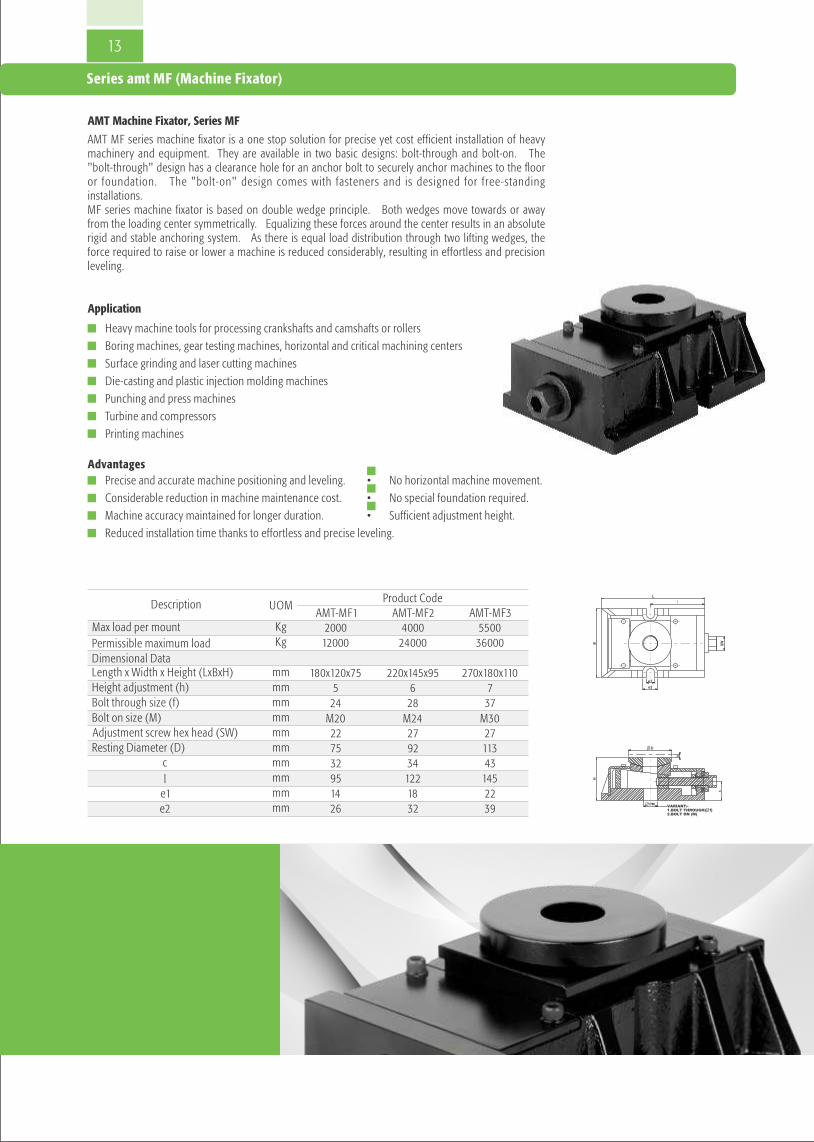
AMT Machine Fixator, Series MF
AMT MF series machine fixator is a one stop solution for precise yet cost efficient installation of heavy machinery and equipment. They are available in two basic designs: bolt-through and bolt-on. The "bolt-through" design has a clearance hole for an anchor bolt to securely anchor machines to the floor or foundation. The "bolt-on" design comes with fasteners and is designed for free-standing installations. MF series machine fixator is based on double wedge principle. Both wedges move towards or away from the loading center symmetrically. Equalizing these forces around the center results in an absolute rigid and stable anchoring system. As there is equal load distribution through two lifting wedges, the force required to raise or lower a machine is reduced considerably, resulting in effortless and precision leveling.
• Heavy machine tools for processing crankshafts and camshafts or rollers
• Boring machines, gear testing machines, horizontal and critical machining centers
• Surface grinding and laser cutting machines• Die-casting and plastic injection molding machines• Punching and press machines• Turbine and compressors• Printing machines
Series amt MF (Machine Fixator)
Product CodeAMT-MF3
550036000
270x180x110737
M3027113
Max load per mountPermissible maximum loadDimensional DataLength x Width x Height (LxBxH)Height adjustment (h)Bolt through size (f)Bolt on size (M)Adjustment screw hex head (SW)Resting Diameter (D)
cl
e1e2
Description UOMAMT-MF1 AMT-MF2
2000 400012000 24000
180x120x75 220x145x955 6
KgKg
mmmm
24 28mmM20 M24mm22 27mm75 92mm
mm 32 34 43mm 95 122 145mm 14 18 22mm 26 32 39
13

14
Precision levelling wedgesDue to their large contact area Bilz precision levelling wedges (PK) for vibration and structure-borne noise insulation offer optimum support and stiffening of the machine bed.They are available in a wide range of sizes and dimensions as free-standing, bolt-on to the machine or bolt-through to the foundation design.
The proven design principle enables the machine to be quickly leveled to a degree of leveling in the 1/100 mm (0.0004”) range even at loads of 100 tons per wedge.The powerful self-locking effect of the leveling bolt prevents self-loosening under the effects of vibration. Depending on the application, their use in conjunction with Bilz isolation pads creates the perfect rigidity with very effective vibration isolation.
On request we supply special solutions in terms of color, isolation pad mounting and dimension.
Allowable temperature range: -20 °C to +120 °C (-5 to +250 °F)
To simplify handling the upper or lower wedge can be secured with a tension spring.
The general tolerances in accordance with ISO 2768 vL apply to the specified lengths and widths. The specified height at the center position is subject to a tolerance of ± 1mm (±0.04").
General information
15
B
L
H
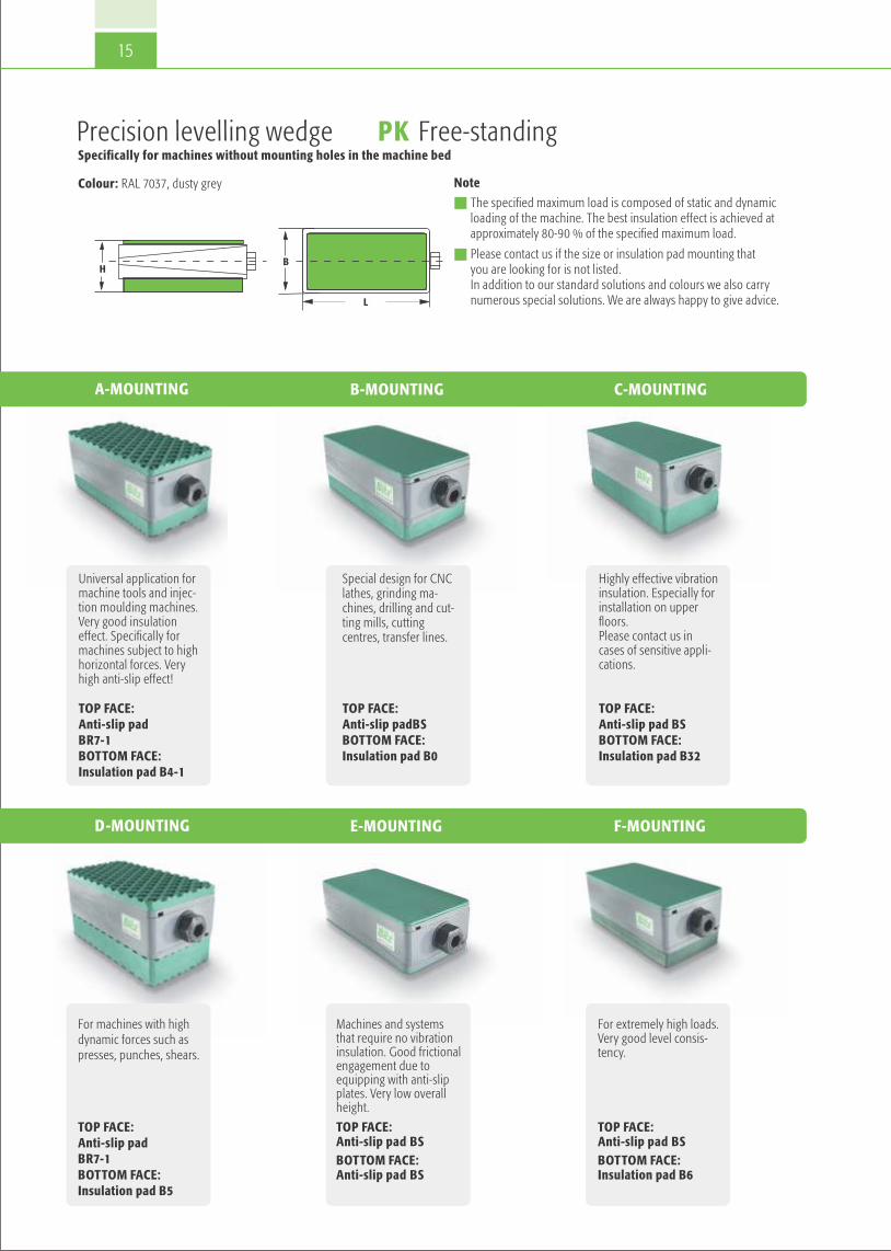
Precision levelling wedge PK Free-standingSpecifically for machines without mounting holes in the machine bed
A-MOUNTING
Note
n The specified maximum load is composed of static and dynamicloading of the machine. The best insulation effect is achieved atapproximately 80-90 % of the specified maximum load.
n Please contact us if the size or insulation pad mounting thatyou are looking for is not listed. In addition to our standard solutions and colours we also carrynumerous special solutions. We are always happy to give advice.
Colour: RAL 7037, dusty grey
Highly effective vibrationinsulation. Especially forinstallation on upperfloors.Please contact us incases of sensitive appli-cations.
TOP FACE:Anti-slip pad BSBOTTOM FACE:Insulation pad B32
Universal application formachine tools and injec-tion moulding machines. Very good insulation effect. Specifically formachines subject to highhorizontal forces. Very high anti-slip effect!
TOP FACE: Anti-slip padBR7-1BOTTOM FACE: Insulation pad B4-1
Special design for CNClathes, grinding ma-chines, drilling and cut-ting mills, cuttingcentres, transfer lines.
TOP FACE:Anti-slip padBSBOTTOM FACE:Insulation pad B0
B-MOUNTING C-MOUNTING
D-MOUNTING E-MOUNTING F-MOUNTING
For extremely high loads.Very good level consis-tency.
TOP FACE:Anti-slip pad BSBOTTOM FACE:Insulation pad B6
Machines and systemsthat require no vibrationinsulation. Good frictionalengagement due toequipping with anti-slipplates. Very low overallheight.
TOP FACE:Anti-slip pad BSBOTTOM FACE:Anti-slip pad BS
For machines with highdynamic forces such aspresses, punches, shears.
TOP FACE:Anti-slip padBR7-1BOTTOM FACE:Insulation pad B5

16Right to make technical changes is reserved.
PK 1PK 2PK 2.5PK 3PK 3/72PK 3.2PK 3.5PK 3.8PK 4PK 4/72PK 4.5PK 5PK 5.5PK 6PK 7PK 8PK 9
Type Overall Dimensions
Lmm
Bmm
105150115200200150115170200200180200300250300400500
5575
1159595
150250170200200230250250330400500600
5401,0001,2001,8001,8002,0002,6002,6003,8003,8003,9004,8007,3008,000
11,75019,55029,450
A-Mounting
Load Kg/Pc
H Center Position mm
596367679468927670948494
106949595
137
B-Mounting
Load Kg/Pc
H Center Position mm
1,0002,1002,5003,6003,6004,3005,5005,5007,7007,7007,9509,700
14,40016,100
23,60039,30059,100
545862628963877165897989
101899090
132
C-Mounting
Load Kg/Pc
H Center Position mm
460870
1,0001,4601,4601,7002,2002,2003,1003,1003,2003,9005,8006,4509,450
15,70023,600
646872729973978175998999
11199
100100142
Adjustment Range mm
+4/-5 +5/-6 +4/-5 +5/-5 +5/-4 +5/-6 +4/-8 +6/-8 +5/-7 +5/-7 +9/-9 +10/-7 +10/-8 +7/-10 +8/-12 +8/-14 +12/-15
PK 1PK 2PK 2.5PK 3PK 3/72PK 3.2PK 3.5PK 3.8PK 4PK 4/72PK 4.5PK 5PK 5.5PK 6PK 7PK 8PK 9
Type Overall Dimensions
Lmm
Bmm
105150115200200150115170200200180200300250300400500
5575
1159595
150250170200200230250250330400500600
8701,7002,0002,9002,9003,4504,4504,4506,2006,2006,4007,700
11,60012,90018,90031,40047,000
D-Mounting
Load Kg/Pc
H Center Position mm
69737777
10478
1028680
10494
104116104105105147
E-Mounting
Load Kg/Pc
H Center Position mm
1,6003,2503,8005,4905,4906,5008,3508,350
11,64011,64012,00014,55021,80024,20035,50058,95088,700
41454949765074585276667688767777
119
F-Mounting
Load Kg/Pc
H Center Position mm
1,9003,8004,4506,4006,4007,5809,7009,700
13,50013,50013,95017,00025,30028,20041,40068,000
1,03,500
545862628963877165798989
101899090
132
Adjustment Range mm
+4/-5 +5/-6 +4/-5 +5/-5 +5/-4 +5/-6 +4/-8 +6/-8 +5/-7 +5/-7 +9/-9 +10/-7 +10/-8 +7/-10 +8/-12 +8/-14 +12/-15
Ld
Bee
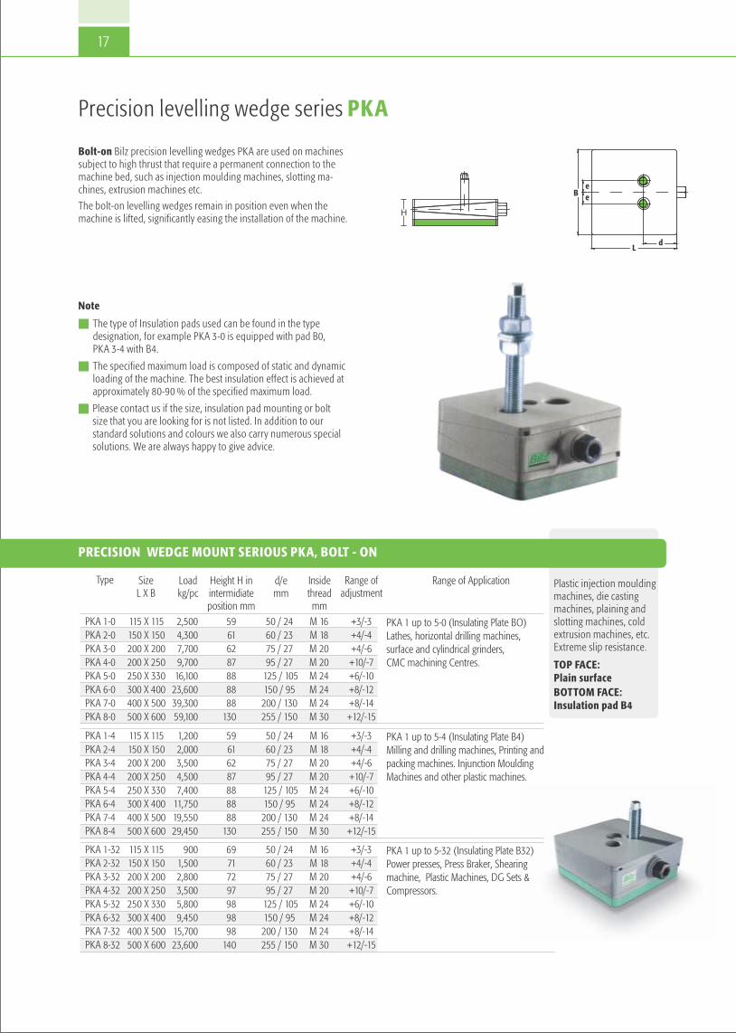
Precision levelling wedge series PKA
Note
n The type of Insulation pads used can be found in the type designation, for example PKA 3-0 is equipped with pad B0, PKA 3-4 with B4.
n The specified maximum load is composed of static and dynamicloading of the machine. The best insulation effect is achieved atapproximately 80-90 % of the specified maximum load.
n Please contact us if the size, insulation pad mounting or boltsize that you are looking for is not listed. In addition to ourstandard solutions and colours we also carry numerous specialsolutions. We are always happy to give advice.
Bolt-on Bilz precision levelling wedges PKA are used on machinessubject to high thrust that require a permanent connection to themachine bed, such as injection moulding machines, slotting ma-chines, extrusion machines etc.
The bolt-on levelling wedges remain in position even when themachine is lifted, significantly easing the installation of the machine.
PRECISION WEDGE MOUNT SERIOUS PKA, BOLT - ON
Range of Application
PKA 1-32PKA 2-32PKA 3-32PKA 4-32PKA 5-32PKA 6-32PKA 7-32PKA 8-32
Type
PKA 1-0 PKA 2-0 PKA 3-0PKA 4-0PKA 5-0PKA 6-0PKA 7-0PKA 8-0
PKA 1-4PKA 2-4 PKA 3-4PKA 4-4PKA 5-4PKA 6-4PKA 7-4PKA 8-4
115 X 115 150 X 150 200 X 200200 X 250250 X 330300 X 400400 X 500500 X 600
Size L X B
115 X 115 150 X 150 200 X 200200 X 250250 X 330300 X 400400 X 500500 X 600
115 X 115 150 X 150 200 X 200200 X 250250 X 330300 X 400400 X 500500 X 600
9001,5002,8003,5005,8009,450
15,70023,600
Load kg/pc
2,5004,3007,7009,70016,100
23,60039,30059,100
1,2002,0003,5004,5007,400
11,75019,55029,450
69717297989898
140
Height H in intermidiate position mm
59616287888888
130
59616287888888
130
50 / 2460 / 2375 / 2795 / 27
125 / 105150 / 95200 / 130255 / 150
d/e mm
50 / 2460 / 2375 / 2795 / 27
125 / 105150 / 95200 / 130255 / 150
50 / 2460 / 2375 / 2795 / 27
125 / 105150 / 95200 / 130255 / 150
M 16M 18M 20M 20M 24M 24M 24M 30
Inside thread mmM 16M 18M 20M 20M 24M 24M 24M 30
M 16M 18M 20M 20M 24M 24M 24M 30
+3/-3+4/-4+4/-6+10/-7+6/-10+8/-12+8/-14+12/-15
Range of adjustment
+3/-3+4/-4+4/-6+10/-7+6/-10+8/-12+8/-14+12/-15
+3/-3+4/-4+4/-6+10/-7+6/-10+8/-12+8/-14+12/-15
PKA 1 up to 5-32 (Insulating Plate B32)Power presses, Press Braker, Shearing machine, Plastic Machines, DG Sets &Compressors.
PKA 1 up to 5-0 (Insulating Plate BO) Lathes, horizontal drilling machines, surface and cylindrical grinders, CMC machining Centres.
PKA 1 up to 5-4 (Insulating Plate B4)Milling and drilling machines, Printing andpacking machines. Injunction Moulding Machines and other plastic machines.
Plastic injection mouldingmachines, die casting machines, plaining andslotting machines, coldextrusion machines, etc.Extreme slip resistance.
TOP FACE:Plain surfaceBOTTOM FACE:Insulation pad B4
H
17

Ld
Bee
Bolts: Not supplied as a standard scope can be supplied on request
Note
n The type of insulation pads used can be found in the type designation, for example PKD 3-0 is equipped with pad B0,PKD 3-4 with B4.
n The specified maximum load is composed of static and dynamicloading of the machine. The best insulation effect is achieved atapproximately 80-90 % of the specified maximum load.
n Please contact us if the size, insulation pad mounting or boltsize that you are looking for is not listed. In addition to ourstandard solutions and colours we also carry numerous specialsolutions. We are always happy to give advice.
Bolt-through Bilz precision levelling wedge PKD are used on machines that necessarily need to be anchored due to un-favourable centre of gravity proportions. Also for machines thatmust be pushed or pulled when levelling – and for machines with low intrinsic rigidity.
PKD 1-0 TO PKD 8-0
Boring and cutting mills,machining centres, special machines, longbed lathers, long bedplaining machines.
TOP FACE:Plain surfaceBOTTOM FACE: Insulation pad B0
Type
PKD 1-0PKD 2-0PKD 3-0PKD 3/72-0PKD 4-0PKD 5-0PKD 6-0PKD 7-0PKD 8-0
Precision levelling wedge series PKD
max. loadKg/pc.
2,5004,3007,7007,7009,700
16,10023,60039,30059,100
HCentre position
mm6061638787878888
130
Drill hole
222326262630303535
Adjustment range
mm+4/-5+5/-6+3/-7+4/-7
+10/-7+6/-10+8/-12+8/-14
+12/-15
115150200200200250300400500
L
mm115150200200250330400500600
B
mm5058767695
125150200255
d
mm2423272727
10595
130150
e
mm
H
18

19
B
Ø D±3°
e
e
dL
Note
n The type of insulation pads used can be found in the type designation, for example PKDK 3-0 is equipped with B0, PKDK 3-4 with B4.
n The specified maximum load is composed of static and dynamicloading of the machine. The best insulation effect is achieved atapproximately 80-90 % of the specified maximum load.
n Please contact us if the size, insulation pad mounting or boltsize that you are looking for is not listed. In addition to ourstandard solutions and colours we also carry numerous specialsolutions. We are always happy to give advice.
Precision levelling wedge with spherical seat Series PKAK / PKDK
Bilz precision levelling wedge PKAK (bolt-on)/ PKDK (bolt-through) with spherical seat to compensate for angle differencesbetween machines and foundations, e.g. non processed machinemounts or uneven floors. Specifically for machines with a longbed and higher demands on geometry.
PKAK / PKDK 1-0 TO PKAK / PKDK 4-0 WITH SPHERICAL SEAT
TOP FACE SPHERICALSEAT: PaintedBOTTOM FACE:Insulation pad B0
Type
PKAK 1-0PKAK 2-0PKAK 3-0PKAK 4-0
PKDK 1-0PKDK 2-0PKDK 3-0PKDK 4-0
Adjustment rangemm
+3/-3+4/-4+4/-6
+10/-7
+4/-5+5/-6+3/-7
+10/-7
Right to make technical changes is reserved.
max. load
Kg/pc
25,0043,0077,0097,00
25,0043,0077,0097,00
HCentre position
mm707779
103
707779
103
115150200200
115150200200
L
mm
115150200250
115150200250
B
mm
110150150150
110150150150
O/D
mm50587695
50587695
d
mm
24232627
24232727
e
mm
22232626
M16 M18 M20 M20
InternalThread
Drill Holemm

Size 1
Size 2
Type
Size 1 Size 2
max. load Kg/pc.
1,650 1,650
a
mm 140 160
b
mm 125 180
c
mm 45 55
d
mm 60 -115 60 -140
e
mm 50 48
f
mm 25 43
g
mm 35 37
i
mm17.522
Size 1Steel angle, Levelling element Type BNVS 115/5, 3 bolts M16 x 150, 2 anchors M16
Size 2Steel angle, Levelling elementType BNVS 115/5, 4 bolts M20 x 150, 3 anchors M20
20
Structure bornenoise insulation inrigidly anchoredmachines andpipe suspensions.
INSULATION WASHERS TO INSULATE THE BOLT HEAD
Accessories
Our insulation washers for bolt heads offer adequate vibration and structure bornenoise insulation in rigidly anchored machines and components.
They can be used at temperatures between -20 and +120 °C and are distinguishedby their high resistance to oils, greases, acids and coolants used in industry.
HORIZONTAL ELEMENTS
Right to make technical changes is reserved.
for bolts
Øto M12to M20to M30
outer Ø
mm355070
inner Ø
mm132131
Installation heightmm 202225
max. preload force
kg 79150290
max. tightening torque
Nm51645

FAEBIRubber air spring insulator
®
Highly effective insulation of vibrations, shocks and structure borne noise for machines, apparatus and aggregates.
21

Load [Kg]
0 15 30 45 60
Load [Kg]
25 50 75 100 125 150
Load [Kg] Load [Kg]
50 100 150 200 250 300 20 25 30 35 40 45
Load [Kg] Load [Kg]
200 350 500 650 800 450 700 950 1200 1450
Load [Kg] Load [Kg]
1000 1500 2000 2500 3000 2500 3500 4500 5500 6500
Load [Kg]
5000 6500 8000 9500 11000 12500
FAEBI rubber air springs are used for thehighly effective insulation of machines, apparatus and aggregates from shocks, vibrations and structure borne noise. Theelement comprises of a bell-shaped rubberform made from high-grade elastomer witha reinforced side wall. The constructive design does not only achieve excellent insulation properties, but also very high mechanical stability. Damage due to over-load or a sudden pressure drop is virtuallyimpossible. The air spring element has avery low degree of deflection in the horizontal direction. The inclusion of anti-slip pads on the spring element baseplate means that additional floor anchoringis not usually required.
®
Note:
n FAEBI elements can also be suppliedin stainless steel designs and fromEDPM elastomer for outdoor use (suchas air conditioning).
®
n To reduce the movement amplitude inthe vertical direction the FAEBI- HDvariant is supplied with additionaldamping.
®
Applications
Perfectly suited for source insulation offast running presses, forging hammers andother machines and aggregates with highlydynamic disturbance forces. Passive insula-tion of measuring and test equipment aswell as highly accurate machine tools. Canalso be combined with mechanical levelcontrol on request.
SHOCK AND VIBRATION INSULATION
The natural frequency of the rubber airspring in the vertical direction is between3 and 14 Hz depending on the allowablestatic load and variant. The maximumspring deflection in response to a pulseload is up to 15mm depending on thetype and size of the air spring.
FAEBI® RUBBER AIR SPRING INSULATOR
Right to make technical changes is reserved.
22

A
G
23
SERIES TYPE FAEBI®
Note
n Ensure that the element is selected so that the maximum load (static and dynamic load) is not exceeded! For applications with higher dynamics harder variants of the FAEBIreduce the deflection of the element. However, the softer the element is, the better the achievable insulation effect is. Please contact us, we are happy to assist with selecting a suitable element.
®
n If the bottom edge of the machine does not completely cover ØD,we recommend the use of our special protective cover
n Permissible temperature range: -20 °C to +80 °C
n The elements are attached to the holes provided on the machine using the bolts supplied (see Accessories). Anchoring to the floor is usually not necessary.
n Bolt in the bolt by hand only, do not use a wrench. Also only tighten the nut with low torque.
n The machine is placed on the deflated element, which is then inflated in stages using the standard valve until dimension H(= working height) is reached. The maximum specified air pressure must also not be exceeded!
n Inflation and deflation may only take place under load (observe the maximum permissible pressure).
n Up to +/- 5 mm are available for levelling.
Right to make technical changes is reserved.
®FAEBI 50
®FAEBI 75
®FAEBI 100
®FAEBI 125
®FAEBI 150
®FAEBI 200
®FAEBI 300
®FAEBI 430
®FAEBI 580
Type
StandardStandard + BR7-1SoftSoft + BR7-1StandardStandard + BR7-1SoftSoft + BR7-1Super SoftSuper Soft + BR7-1StandardStandard + BR7-1SoftSoft + BR7-1Super SoftSuper Soft + BR7-1StandardStandard + BR7-1SoftSoft + BR7-1Super SoftSuper Soft + BR7-1HartStandardSoftSuper SoftHartStandardSoftSuper SoftHartStandardSoftHartStandardSuper HartHartStandard
Variant
20–6020–5010–5010–45
40–15040–13535–13035–12030–105 30–105 75–300 75–300 60–260 60–260 55–240 55–240
260–460260–460240–405240–405220–350220–350260–850250–800240–700230–650
700–1,500625–1,500600–1,300550–1,150
1,200–2,8001,150–2,7001,050–2,5003,000–6,6002,750–6,5005,400–12,0005,200–11,5005,150–11,000
LoadKg/pc.
32.52.52.33
2.72.62.42.12.155
4.44.444
5.55.54.94.94.24.26.46
5.34.966
5.24.66.56
5.66.16
6.66.36
max. Pressurebar
110110110110115115115115115115135135135135135135165165165165165165200200200200260260260260370370370500500680680680
Amm
80808080979797979797118118118118118118140140140140140140170170170170236236236236340340340480480650650650
ØDmm
6062606263656365636562646264626493959395939591919191919191918989898989898989
H approx. mm = Working height
6168616867746774677465726572657298105981059810596969696959595959393939494919191
H (deflated)
mm
3535353543434343434360606060606066666666666680808080130130130130200200200315 315 380380380
Ødmm
5555555555555555555555888888888881212141414
hmm
M10M10M10M10M12M12M12M12M12M12M12M12M12M12M12M12M16M16M16M16M16M16M16M16M16M16M16M16M16M16M20M20M20M20M20M24M24M24
Gmm
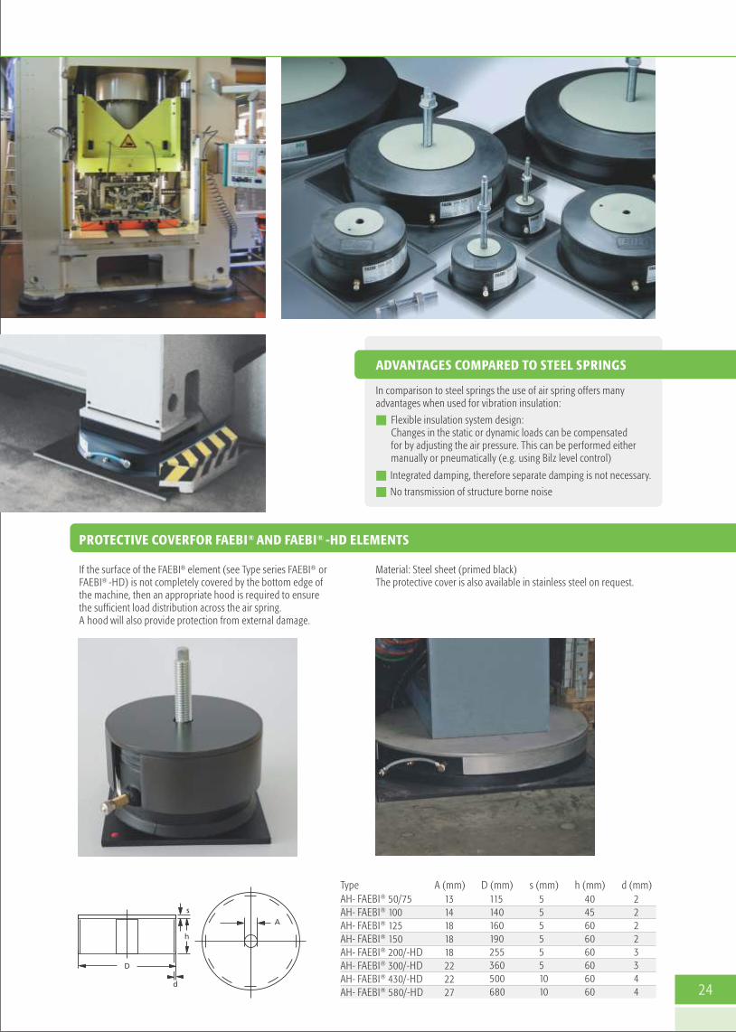
ADVANTAGES COMPARED TO STEEL SPRINGS
In comparison to steel springs the use of air spring offers manyadvantages when used for vibration insulation:
n Flexible insulation system design: Changes in the static or dynamic loads can be compensatedfor by adjusting the air pressure. This can be performed eithermanually or pneumatically (e.g. using Bilz level control)
n Integrated damping, therefore separate damping is not necessary.
n No transmission of structure borne noise
Material: Steel sheet (primed black) The protective cover is also available in stainless steel on request.
® ®PROTECTIVE COVERFOR FAEBI AND FAEBI -HD ELEMENTS
® ®If the surface of the FAEBI element (see Type series FAEBI or ® FAEBI -HD) is not completely covered by the bottom edge of
the machine, then an appropriate hood is required to ensure the sufficient load distribution across the air spring.A hood will also provide protection from external damage.
d (mm)22223344
Type ®AH- FAEBI 50/75®AH- FAEBI 100®AH- FAEBI 125®AH- FAEBI 150®AH- FAEBI 200/-HD®AH- FAEBI 300/-HD®AH- FAEBI 430/-HD®AH- FAEBI 580/-HD
A (mm) 1314181818222227
D (mm) 115140160190255360500680
s (mm) 5555551010
h (mm) 4045606060606060 24

Type series FAEBI® -HD with adjustable damping
The combined rubber-air spring insulator FAEBI -HD with adjustable damping comprises of an elastomer metal bonding with reinforced side wall and a two-chamber system. To achieve the greatest possible damping effect the interior of theair spring is divided into two air chambers connected by an airhose (load and damping volume). An adjustable throttle valve isused to set the flow cross section to the desired damping effectfrom the outside. The significantly higher damping effect compared to a single chamber system (FAEBI ) reduces the resonance amplification substantially and the machine movementsfade noticeably faster. The increased energy substancially absorp-tion also has a positive effect on the manufactured goods and onmachine and tool wear.
®
®
Benefits:In comparison to viscous damping air damping is absolutely free of wear and maintenance-free and the damping factor can be easily adjusted from outside.
Note
n Ensure that the element is selected so that the maximum load(static and dynamic load) is not exceeded! For applicationswith higher dynamics harder variants of the FAEBI reduce thedeflection of the element. However, the softer the element is,the better the achievable insulation effect is. Please contactus, we are happy to assist with selecting a suitable element.
®
n If the bottom edge of the machine does not completely coverØD, we recommend the use of our special protective cover
n Permissible temperature range: -20 °C to +80 °C
n The elements are attached to the holes provided on the machine using the bolts supplied Anchoring tothe floor is usually not necessary.
n Bolt in the bolt by hand only, do not use an open-endwrench. Also only tighten the nut with low torque.
n The machine is placed on the deflated element, which is theninflated in stages using the standard valve until dimension H(= working height) is reached. The maximum specified airpressure must also not be exceeded!
n Inflation and deflation may only take place under load, observe the maximum permissible pressure.
n Up to +/- 5 mm are available for levelling.
SETTLING BEHAVIOUR FAEBI®
Without adjustable damping (single chamber system) With adjustable damping (twin chamber system)
Time in seconds
FAEBI® without adjustable damping
Vibr
atio
n ac
cele
ratio
n in
G
0.1
0.08
0.06
0.04
0.02
0
-0.02
-0.04
-0.06
-0.08
-0.1
0.5 1 1.5 2
SETTLING BEHAVIOUR FAEBI® -HD
Time in seconds
FAEBI® with adjustable damping
Vibr
atio
n ac
cele
ratio
n in
G
0.1
0.08
0.06
0.04
0.02
0
-0.02
-0.04
-0.06
-0.08
-0.1
0.5 1 1.5 2
25

FAEBI® 200-HD
FAEBI-HD
Super Hart Hart Standard
FAEBI® 300-HD FAEBI® 430-HD FAEBI® 580-HD
FAEBI® -HD
NATURAL FREQUENCIES FAEBI® 200-HD TO 580-HD
Right to make technical changes is reserved.
Bypass for adjustabledamping
Fillingvalve Top chamber
Bottom chamber
Variant
HartStandardHartStandardHartStandardSuper HartHartStandard
H approx. mm = Working height
898989899191
126126126
®FAEBI 200-HD
® FAEBI 300-HD
® FAEBI 430-HD
® FAEBI 580-HD
Type
700–1,500625–1,500
1,400–2,9501,150–2,7003,000–6,6002,750–6,5006,000–11,5005,600–10,8004,700–10,000
LoadKg/pc
66
6.56
6.16
6.96.56
max.Pressure bar
260260370370500500680680680
Amm
236236340340480480650650650
/O Dmm
H (deflated)
909094939796135133130
mm130130200200315 315 380380380
/O dmm
88881212141414
hmm
M16M16M20M20M20M20M24M24M24
Gmm
FAEBI-HD
02468
1012141618
F - HDAEBI 200
Vert
ical
nat
ural
freq
uenc
y [H
z]
Load [Kg]500 700 900 1100 1300 1500 1700
0
2
4
6
8
10
12
14
16
Vert
ical
nat
ural
freq
uenc
y [H
z]
Load [Kg]1000 1500 2000 2500 3000
0
2
4
6
8
10
12
14
16
Vert
ical
nat
ural
freq
uenc
y [H
z]
Load [Kg]2500 3500 4500 5500 6500
0
1
2
3
4
5
6
7
8
FFAEBI 580AEBI 580--HHD
Vert
ical
nat
ural
freq
uenc
y [H
z]
Load [Kg]4500 6000 7500 9000 10500 12000
26
F 3 - HDAEBI 00 F 43 - HDAEBI 0

27
FAEBI ® MPN-LCV
The mechanical-pneumatic level control (MPN) with our robustproportional valve LVC represents a simple but effective solutionfor preventing skew positions resulting from load changes. A plunger continuously probes the level and the position of theplunger is transmitted to a slide valve. The air spring is eitherpressurized or the internal pressure is vented in accordance withthe position of the plunger. The adjustable target level is maintained within an accuracy of ± 1/10 mm. In principle three control valves are used, that optionally have anupstream air maintenance unit for conditioning the pneumatic airsupply, limiting the system pressure to 6 bar, removing accumu-lated condensate and filtering out solid particles (rust and dust).
® ®FAEBI AND FAEBI -HDwith mechanical-pneumaticlevel control (MPN-LCV)
Air maintenance unit Compressed air supply(max. 10 bar)
Control valve
Air spring

BiAirMembrane air spring insulator
®
®Low-frequency Bilz BiAir membrane air spring with precisely adjustable damping for effective vibration insulation of sensitive measurement and testing equipment, precisefinishing machines, laser equipment and optical and electronic instruments as well as vehicle, engine and gearbox test beds, etc.
28

29
Without insulation
With insulation
n Highly effective vibration insulation of
n sensitive measurement and testing equipment,
n precise finishing machines,
n laser equipment as well as optical and electronic instruments.
n Vibration insulated bearings for vehicle, engine and gearbox test beds
n Foundation insulation
Advantages compared to conventional steel springs®The use of Bilz BiAir air spring insulators with active level
control constantly maintains the correct level of machines orfoundations. The level control and adjustment is completelyautomatic! The pressure in the air springs is appropriately adjusted by in-or deflating in response to load changes. This keeps the insulating effect constant in every case. Unlike steel springs air springs do not transmit structure-bornesound.
®The BiAir membrane air spring insulator is made of turned orcast aluminium. The air space is enclosed by a thin-walled flexibleand pressure-resistant rolling membrane. A piston sits on top ofthe membrane and is pressed into the air space.
This design allows a highly-effective insulation against vibration. In order to simultaneously achieve a high degree of damping, the air space within the insulator is divided into two chambers connectedwith an air tube (load/damping volume). An adjustable throttlevalve is used to set the flow cross section to the desired dampingeffect from the outside. The friction in the air flow generated bythe throttle valve can create a damping effect of up to 15 %.
Damage to the rolling membrane due to overpressure is virtuallyexcluded through the use of additional safety valves or a mechan-ical piston stroke limit.
With/without insulation
®BiAir MEMBRANE AIR SPRING INSULATOR WITH ADJUSTABLE DAMPING
Frequency [Hz]
a in [m
m/s
2]
CMM Mounted on BiAir
30
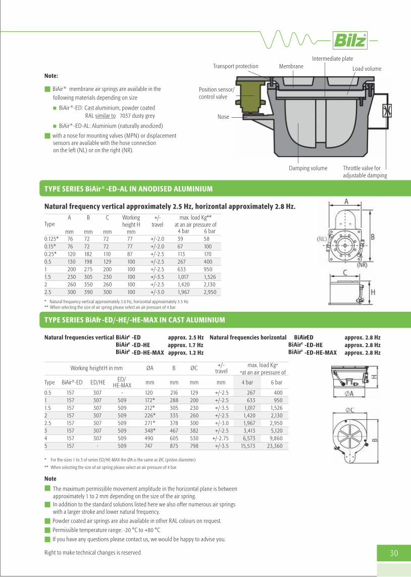
Note:
n BiAir® membrane air springs are available in the following materials depending on size
n BiAir ®-ED: Cast aluminium, powder coatedRAL similar to 7037 dusty grey
n BiAir® -ED-AL: Aluminium (naturally anodized)
n with a nose for mounting valves (MPN) or displacement sensors are available with the hose connection on the left (NL) or on the right (NR).
®TYPE SERIES BiAir -ED-AL IN ANODISED ALUMINIUM
TYPE SERIES BiAir® -ED/-HE/-HE-MAX IN CAST ALUMINIUM
* Natural frequency vertical approximately 3.0 Hz, horizontal approximately 3.5 Hz** When selecting the size of air spring please select an air pressure of 4 bar.
* For the sizes 1 to 3 of series ED/HE-MAX the ØA is the same as ØC (piston diameter)
** When selecting the size of air spring please select an air pressure of 4 bar.
Intermediate plate
Load volume
Damping volume
Membrane
Nose
Transport protection
Position sensor/control valve
Throttle valve for adjustable damping
Natural frequency vertical approximately 2.5 Hz, horizontal approximately 2.8 Hz.
Natural frequencies vertical ® -ED-ED-HE-ED-HE-MAX
approx. 2.5 Hzapprox. 1.7 Hzapprox. 1.2 Hz
BiAir®
BiAir®
Natural frequencies horizontal BiAir® -ED-ED-HE-ED-HE-MAX
BiAir®
BiAir®
Note
n The maximum permissible movement amplitude in the horizontal plane is between approximately 1 to 2 mm depending on the size of the air spring.
n In addition to the standard solutions listed here we also offer numerous air springs with a larger stroke and lower natural frequency.
n Powder coated air springs are also available in other RAL colours on request.
n Permissible temperature range: -20 °C to +80 °C
n If you have any questions please contact us, we would be happy to advise you.
Right to make technical changes is reserved.
approx. 2.8 Hzapprox. 2.8 Hzapprox. 2.8 Hz
max. load Kg*
*at an air pressure of
4 bar 6 barType
0.511.522.5345
ØA
mm
120172*212*226*271*348*490747
B
mm
216288305335378467605875
ØC
mm
129200230260300382530798
Working height H in mm
BiAir®-ED ED/HE ED/HE-MAX
157157157157157157157157
307307307307307307307
-
-509509509509509509509
+/-travel
mm
+/-2.5+/-2.5+/-3.5+/-2.5+/-3.0+/-2.5
+/-2.75+/-3.5
267633
1,0171,4201,9673,4136,573
15,573
400950
1,526 2,1302,9505,1209,860
23,360
Type
0.125*0.15*0.25*0.511.522.5
A
mm7676120130200230260300
B
mm7272182198275305350390
Workingheight H
mm777787100100100100100
+/-travel
+/-2.0+/-2.0+/-2.5+/-2.5+/-2.5+/-3.5+/-2.5+/-3.0
max. load Kg**at an air pressure of
39671132676331,0171,4201,967
4 bar581001704009501,5262,1302,950
6 bar
C
mm7272110129200230260300
BiAir

31
MPN Mechanical pneumatic levelcontrol for Bilz air springs
Bilz mechanical pneumatic level control for air spring systems ® ® ®with FAEBI and FAEBI -HD rubber or BiAir membrane air springs.
Powerful vibration insulation at very high level consistency.

32
MPN-LCV MPN-PVM
Mechanical pneumatic level control MPNBilz level control systems are significant components in the
®optimum function of vibration insulation using FAEBI and® ®FAEBI -HD rubber or BiAir membrane air springs. They prevent
impermissible and undesired deflection of the insulators or an out-of-level condition of the machine that can be caused by load changes on an air spring mounted machine or system.Rapidly adding or venting air enables the air pressure within the air spring to be matched to the respective load, automati-cally controlling the height of the individual air springs. This enables the highest degree of stability and effective insulationeven with changes in the centre of gravity.
Valve functions
The level is continuously sensed using the plunger. The position of the plunger is directly applied to the slide valveand the air spring is either pressurized or vented. The target levelis adjusted by turning the knurled adjustment ring. The heightand level of the machine is adjusted using three valves.
Design
At least three air springs are controlled (Fig. 1). If more insulators are required due to reasons of design or load, the systemmust still be worked in three controlled groups, as otherwisethe system is statically overdetermined. This is achieved byusing multiple insulators in parallel as a group (Fig.2). An additional air maintenance unit is installed upstream of the control valves to prepare the compressed air.
Fig. 1
Group
Fig. 2
Air maintenanceunit Air maintenance unit
Air spring
Very robust galvanised proportional valve. Level accuracy is ap-® ®proximately ± 1/10 mm. Suitable for Bilz FAEBI , FAEBI -HD
®and BiAir air spring insulators.
Available in the following versions:- MPN-LCV: Standard version of the LCV with hard metal discs
- MPN-LCV-KURZ-Pad-A: Shortened version of the LCV with plunger insulation pad
High-precision yellow chromed proportional valve.®Level accuracy is ± 1/100 mm. Suitable for Bilz BiAir air
spring insulators.
Available in the following versions:- MPN-PVM: Standard version of the PVM with carbide washers
- MPN-PVM-KURZ-Pad-A: Shortened version of the PVM with stem insulation pad
Note
n Supplied as a complete set which includes the 3 control valves and all necessary hose lines and connectors. All components are also individually available as spare parts.
n In addition to the standard solutions listed here we also hold special versions with regard to material, flow, accuracy and restoring force.
n On the LCV variant the air flow can be reduced using the throttle valve should the control system tend to overshoot.The PVM variant can also be fitted with a throttle valve as an option.
n If you have any questions please contact us, we would be happy to advise you.
Controlvalve

33
Vibration insulated tablesIndividually tailored to your requirements.

34
Dimensions
Applications
n Vibration-sensitive measuring and testing equipment
n Laser equipment
n Optical and electronic instruments
n Scales
n Medical instruments
Technology
The Bilz laboratory table LTH is a vibration insulated work placeand can be used for all applications where vibrations and/orchanges in level cause sustained disturbances to the experiment or work.Disturbing vibrations from the environment are isolated by meansof highly effective membrane air spring insulators and the solidhard stone plate.At the same time the mechanical-pneumatic level control automati-cally ensures that the level is retained to an accuracy of up to±1/100 mm even with load changes.The maintenance unit for compressed-air conditioning is included.
LTH laboratory tableParticularly robust and resistant, dynamic applications
Product properties
n Adjustable table feet
n Rigid, welded steel subframe
n ®BiAir membrane air spring (vertical natural frequencya pproximately 3 Hz) between the subframe and table top
n Mechanical-pneumatic level control (level accuracy ± 1/100 mm or ± 1/10 mm, depending on the valve used)
n Table top made from hard stone with a ground finish
n Painting as desired by the customer
n Working height 76 cm
LTH LABORATORY TABLE STANDARD SIZES
Further dimensions are available on request Right to make technical changes is reserved.
Width [mm]Depth [mm]Thickness [mm]Working Height [mm]max load [Kg]
LTH 60-50600500100760250
800600120760250
LTH 80-601,000
630100760300
LTH 100-63900750100760360
LTH 90-751,000
800140760700
LTH 100-801,0001.000
160760700
LTH 100-1001,200
800160700700
LTH 120-801,5001.000
190760
1, 800
LTH 150-1002,0001.000
220760
2,800
LTH 200-100

35
Applications
n Construction of laser optical systems and interferometers
n Special microscopes
Technology
Work places from Bilz are distinguished by their excellent qualityand functionality. Optical work places should offer optimum rigidity and damping with low density. Bilz LTO honeycomb tops are optimised in regard to their damping response so that the usual high resonance amplitude inthe higher frequency range are attenuated by the tables in the HDseries by their natural damping.
LTO optical table Excellent quality and functionality, dynamic applications
Product properties
n As LTH
n Optical table tops:– HD steel honeycomb core with high natural damping, cover plate without thread insert– HDT as HD, but with thread inserts
n Variants: Standard, clean room (base plate in stainless steel)
n ® ®Also available with BiAir OC or BiAir PAS as an option n Working height 76 cm
LTO OPTICAL TABLE STANDARD SIZES
Description of the table tops:
Cover plate: Stainless steel 3 mm, magnetic or non-magnetic, anti-reflective.
Base plate: Steel sheet 3 mm
Clamping hole grid: 25 mm (standard)
Core: HD/HDT: Steel honeycomb made of galvanised 0.5 mm steel sheet, precision formed, bonded with specifically matched resinThread inserts (HDT): Floating mounted threaded inserts M6,
closed sleeves prevent any contact withthe table core. Capability to displace the clamping bolts by 0.5 mm whilst simultaneously inclining by ±3°. Maximum depth of thread 30 mm.
DimensionsWidth [mm]Depth [mm]Thickness [mm]Working Height [mm]max load [Kg]
LTO 60-50600500100760150
900600100760200
LTO 90-601,200
600100760300
LTO 120-601,500
900150760500
LTO 150-902,0001.000
200760500
LTO 200-1002,4001.200
200760750
LTO - 240-1203,0001.500
300760750
LTO 500-150
Further dimensions are available on request Right to make technical changes is reserved.

36
Individual design
Compile the equipment features for the optimuml aboratory table for your application:
n Additional holes/threads in the table top and the subframe
n Special sizes on request
n Can be equipped with metal guide rails on request
Subframe
Levelling elements and rollers are available in various different designs and sizes.
Options
Different frames in standard or special sizes
Cover hood
Holders for
Profiles and bracketsfor additional components
Powder coating in RAL colors
Levelling elements
Set of rolls
Wooden plate:
• Differents sizes
• Cutout
• Rounded corners
Differents materials (wood,metal) and colors for:• Doors• Base plates/inserted plates• Housing
monitor, keyboard,mouse
Arm rest
Insulatorsn Level control (mechanical or electronic)n Accessories (e.g. compressed-air control)n Insulators perfectly integrated in the subframe
FAEBI®BiAir®

37
Right to make technical changes is reserved.
®BILZ-VITAP Vibration insulating table platformProduct properties
n Portable, robust, powder coated metal housing with integrated®Bilz rubber air springs FAEBI or optionally with Bilz
®membrane air springs BiAir
n Equipped with very simple through to very convenient Bilzlevel control systems
n A ground-finished hard stone plate lies on the insulators as a support base and solid base mass
n Available with and without a connection to an external compressed air supply
Applications
n For very light and very small measuring or test equipment
n Weight range up to 200 kg
n Optical devices, optical microscopes, microscopes with a CCDcamera, inspection microscopes, small surface roughness androundness measuring equipment, hardness testers, analyticalbalances, applications in industrial production environments,laboratories and measuring rooms up to clean rooms. Alsosuitable for the portable use of these measuring devices.
VITAP® -F VITAP® -FP VITAP® -BM
With long-term tried and tested®Bilz FAEBI rubber air springs
with non-return valve. Integrated hand pump, no compressed air supplyn ecessary.
With long-term tried and®tested Bilz FAEBI rubber air
springs with precision pressurecontrol for convenient heightadjustment. Connection to an external compressed airsupply.
®With highly efficient Bilz BiAirmembrane air springs and withmechanical-pneumatic levelcontrol (MPN) with automaticlevel compensation in responseto load changes. Connection toan external compressed airsupply.
Item No. Dimensions mmPlatform box
Dimensions mmInstallation surface
Height mm
Load capacitykg
Natural frequencyHz
Compressed air supply
TECHNICAL DATA VITAP® -F, VITAP® -FP, VITAP® -BM
®VITAP -F 50-40®VITAP -F 60-50®VITAP -FP 50-40®VITAP -FP 60-50®VITAP -BM 50-40a®VITAP -BM 50-40b®VITAP -BM 60-50a®VITAP -BM 60-50b
autonomous/air pumpautonomous/air pump
4 bar/air pressure network4 bar/air pressure network6 bar/air pressure network6 bar/air pressure network6 bar/air pressure network6 bar/air pressure network
56-000856-000956-0010 56-0011 56-000656-000556-000256-0003
540 x 440640 x 540540 x 440640 x 540540 x 440540 x 440640 x 540640 x 540
500 x 400600 x 500500 x 400600 x 500500 x 400500 x 400600 x 500600 x 500
99 +/-1.599 +/-1.599 +/-1.599 +/-1.599 +/-1.599 +/-1.599 +/-1.599 +/-1.5
6013060
13075
150150200
4.5–64.5–64.5–64.5–62.5–32.5–32.5–32.5–3

38
Isolated Machine Foundations • Vibration foundation with Insulations Pad sets • Vibration foundation with Rubber Air Spring FAEBI & Level Control • Vibration foundation with BiAir Membrane Air Spring & Level Control

39
FOUNDATION INSULATION
Your benefits from Bilz foundation insulations:
Indirect vibration insulation of a machine or system enhances thenatural rigidity and leads to a significant improvement of the dynamic behaviour in response to large changes in load and traveldistances. The exact design of the foundation according to the machine properties ensures an economic solution for the long-term and trouble-free operation of the system.
We have many years and a wide range of experience in the design and projecting of machine foundations. We therefore offer all of thenecessary services from single source:
n The increased machine rigidity enables effective vibra-tion insulation even with large machines and systems.This results in increased precision, receiver insulationand protects the machine surroundings.
n Reduction of the vibration amplitude by adding additional mass or moment of inertia and lowering ofthe centre of gravity. This results in electronic compo-nents, control, bearings, etc., enduring less stress andthe quality of the results are significantly improved, in particular for applications where the level is critical.
n Smaller relative movements of individual machine components or attachments (such as robots, materialfeeds, etc.)
n Reduction of the size of the foundation compared to thefoundation design without vibration insulation.
n All-round service from one single source; fewer interfaces and contacts.
Direct insulation means that vibrationinsulators are fitted directly under orin the machine, usually at the same locations as the available installationpoints. Direct insulation requires that the machine bed or base frame has sufficient intrinsic rigidity and that itwill not warp or twist due to elasticmounting. In addition the machinegeometry must allow the suitablearrangement of the insulators.
Depending onn Machine dimensions, n Machine centre of gravity, n Dynamic forces acting on the machine,n Permissible machine movement,n Requirements on the insulation,n Mobility (flexible installation site),n Attachment parts or feeds,n Type of installation site
(for example permissible floor loading, installation in above groundfloors of a building),
This is achieved either by providing ablock foundation made of concrete a steel platform or a cast plate. In this case the insulation isreferred to as indirect insulation.
n Vibration analysis on site
n Simulation
n Vibration insulation design
n Design and calculation of the foundation block
n Creation of the complete documentation(such as tender documents, formwork and reinforcement plans)
n Construction supervision
n Installation and commissioning of the vibration insulators
Cast foundation block
DIRECT INSULATION INDIRECT INSULATION
Machines whose intrinsic rigidity is notsufficient for direct insulation require arigidly designed intermediate construc-tion to be fitted between the insulatorsand the machine. This method also allows the positioning of the insulators to be optimised for the application.

Vibration foundation with insulations pad sets Multiple layering of Bilz insulation pads can achieve significantly reduced naturalfrequencies and therefore considerably increase the insulation effect compared with asingle layer of insulation pads.
These pad sets are particularly suitable for large machines and sprung foundations.The vibration insulation and damping properties of these insulation pads remainunchanged even after years of dynamic loading.
Bilz insulation pads are resistant against the most common greases, oils, coolants,cleaning agents as well as acids and alkalis.
40

41
Right to make technical changes is reserved.
Insulation pad sets
Effective insulation pads for highly dynamic machines andfoundations.
The permissible load capacity of a pad lies between 5 and240 Kg/cm depending on the application. The number and size
of the insulating layers and the required distribution of thepad sets is determined specifically for the application by Bilz.
Foundation pit with Bilz insulation pads laid outFor further information contact us to arrange a personal consultation.
Application
NATURAL FREQUENCY
(Pre) load [Kg/cm2]
(Pre) load [Kg/cm2]
1 2 3 4
1 2 3 4

42
1 2
3 4
5 6
7 8
APPLICATION
Installation of a vibration foundation in an automotive plantfor receiver isolation of a milling machine located oppositethe press shop. Total mass of the foundation block 1,200 t.
Image 1, 2, 3: Design with Bilz isolation pads (black) andintermediate spaces with mineral fiber isolation board.
Image 4: Covering of the entire surface with constructionfoil, then with hard fiber boards. Bonding the overlappingareas. Image 5, 6: Installation of the reinforcement. Image 7, 8: Pouring the concrete.

43
Vibration foundationwith FAEBI®
Bilz scope of supply and services
8 x Bilz FAEBI® 580 HD with mechanical-pneumatic level controlMPN-LCV
Planning services
n Creation of the foundation
n Static calculations
n Formwork and reinforcement plans
n Steel and steel bending schedule
Requirements
n A maximum of 3 weeks loss of production.
n Special shape 5 corner
n Tight space conditions and entry to the inspection channelthrough the foundation block
n Extremely small allowable horizontal movements of the machine
n Reliable source isolation for suppressing the disturbing vibrations in the adjacent building, 2. floor, from 10 Hz.
Application example:
Foundation isolation with FAEBI® rubber air springs and level control.Implementation with pre-cast concrete slabs.

APPLICATION
Punching machine, machine weight including the tool andaccessories approximately 23 t, dynamic forces vertical approx. 60 kN, horizontal approx. 30 kN, foundation blockapprox. 5.1 x 3.5 x 1.0 m, weight approx. 40 t.
44

®The foundation insulation using low-frequency BiAir membraneair springs enables an optimum insulation effect. Unlike with the use of pad sets or steel springs the adjustablelevel of the foundation block automatically resets itself in response to load changes through the level control.
Bilz scope of supply and services®8 x Bilz membrane air springs BiAir 4-ED with mechanical-
pneumatic level control MPN-LCV.
Particular general conditions
The processing accuracy required of the roller grinding machinecannot be met due to disturbing influences from adjacent machines and an overhead crane rail. Large travel distances andtools weighing up to 10t cause large load changes that necessitatethe use of a fast, mechanical-pneumatic level control with a levelaccuracy of ± 0.1 mm.
Vibration foundation®with BiAir
Application example:
Foundation insulation with BiAir® membrane air springs and level control. Implementation with pre-cast concrete slab.
45

46
APPLICATION
Gear grinding machine GLEASON PFAUTER P 1200 G, machine weight incl. tool up to 25 t, foundation block approx. 5.2 x 1.9 x 0.7 m, approx. 20 t

47
n Frequency analysis and vibration measurement
n Simulations
n Design, manufacture, delivery, assembly andc ommissioning of total vibration insulation systems
n Manufacture, supply and installation of cast platforms
n Manufacture, delivery and installation of cast plates
Vibration Insulation Platforms & Test Beds
Basic platform Platform for minimum installation heightand for systems with a very high centre of gravity
Platform for low installation height and forsystems with a high centre of gravity
Many applications require indirect insulation due to the require-ments for effective insulation and level control or due to insuffi-cient intrinsic rigidity. If foundation insulation is not possible ase.g.
n installation is on the elevated floors of a building,
n the site of installation is of restricted space,
n the site of installation should be flexible (mobility),
then mounting the machine to a vibration insulated platform is a proven solution.
Usually either welded steel constructions or cast plates are used.Depending on the design of the platform the base of the machineis additionally extended and the centre of gravity is lowered byadding mass or the position of the insulators, which significantlyenhances the stability of the overall system. In this way machineswith a high centre of gravity and/or small base area can also bemounted to very low frequency and therefore soft insulators.
DESIGN EXAMPLES
SERVICES
Platform for integration in double/clean room floors with additional mass for the reduction of vibration peaks

Vibration insulation of test beds Parallel to the ever increasing demands on test beds and test systems for the automotive industry over recent years, the systems for vibration insulation have also been developing at the same pace.
Vibration foundations for special test beds
n Engine test beds
n Articulated test beds
n Formula-1-test beds (BMW, Mercedes, Ferrari, Toyota, Renault)
n Gearbox test beds
n Acoustic test beds
n Rolling road test beds
n Shaker
n Sliding table
n Cylinder test beds
n Special test beds
n Hydropulser
n Road simulation test beds
n Frequency analysis and vibrationmeasurement
n Design, manufacture, delivery, assembly and commissioning of vibration insulation systems
n Production of static and reinforce-ment plans for foundation pits and–blocks
n Preparation of tender documents,price comparison, cost estimation
APPLICATION EXAMPLES
SERVICES
Convenient and powerful air spring systems with level controlhave proven themselves ideal for very advantageous solution concepts. For the vibration insulation of test beds and aggregateswith particularly high dynamic forces an additional seismic massin the form of a concrete foundation is also needed.
Vibration insulation caststeel platform
Vibration insulation concrete block or steel platform
For further information contact us to arrange a personal consultation.
48

49
Measurement and Vibration AnalysisMeasurement of vibrations and shocks using state of the art instruments –FFT Analyser and analysis software
Due to our decades of experience in the fieldof vibration technology and isolation, weguarantee you technically and economicallyreliable problem solutions. The on site measurement and analysis of vibration emissions and immissions is an essential partof our consulting services with regard to vibration and vibration insulation. Based onthe measurement results, we develop vibration technical measures to comply withlegally prescribed limits.
The assessment of periodic and non-periodicvibrations in the frequency range from 1 Hzto 80 Hz is e.g. based on the DIN 4150 “Vibrations in buildings; Effects on persons inbuildings”. Requirements and reference values are stated herein, in general the considerable disturbance of people in domestic properties and similar premises isto be avoided in order to comply with theseregulations.
Procedure
In the first step the maximum value of the vibration levels for the three directional components x, y and z are determined.The largest of these three values KBF maxis compared with the reference values A uand Ao according to Table 1
n If KBFmax is less than or equal to the(lower) reference value of A u, then the requirements of this standard are met.
n If KBFmax is more than the (upper) refer-ence value of A u, then the requirements of this standard are not met.
n For short-term impacts and those that donot occur often, the requirement of thestandard is met if KBF max is less than orequal to Ao.
Another current example of the requirementfor a vibration analysis is the storage of high-precision 3D-measurement machines, as wellas other testing, measuring or grinding machines. Typically measurements must becarried out by such machines at the plannedsite, to ensure that existing ground vibrationsdo not exceed the permitted values (see Chart1). To do this, the vibration acceleration is
determined within a given frequency spectrum (1–100 Hz), as a simple sum valuemeasurement would provide insufficient information about the exact environmentalconditions. The analysis of the accelerationtime signals is carried out using a fast-fourier-analyser, which indicates the correspondingmeasurement value (vibration acceleration ing) for each frequency of the spectrum. If thedisturbances (vibration interference) are outof the permissible range, the appropriate insulation can be determined with the help of our PC calculation program.
Very accurate vibration analysis in the lowerfrequency range are carried out with highlysensitive Geophones. Vibration speeds frombelow 0.01 µm/s in the range from 0.2 to30 Hz can be recorded with the Geophones.Extremely precise measurements of vibrationare necessary for an optimal and customer-specific design, particularly in the semicon-ductor and Nanotech industry as well as forhigh-precision 3D-measurement machines.
Assignment

50
daytime nightime
Line Impact site 1 Impact sites, in whose vicinity only commercial facilities and where appropriate are housed
with the exception of where the owner and manager of operations, as well as supervisory and stand-by persons are housed (see Industrial estates § 9 BauNVO))
2 Impact sites, in whose vicinity mainly commercial facilities are housed (see Industrial estates § 8 BauNVO)
3 Impact sites, where neither predominantly commercial facilities nor predominantly domestic property are housed (see Core areas § 7 BauNVO, mixed areas § 6 BauNVO, village areas § 5 BauNVO) Impact sites, in whose vicinity predominantly or exclusively domestic property is housed (see Pure residential areas § 3 BauNVO, General residential areas § 4 BauNVO, Small housing estates § 2 BauNVO)
4
5 Particularly vulnerable impact sites, for example in hospitals, sanatoriums, in so far as the are situated in those areas specially designated for them.
In brackets the areas of the Federal Land Utilisation Ordinance = BauNVO are specified, usually represented by the designations under line 1 to 4.A schematic equation is not possible because the designations under line 1 to 4 are only made after the grounds have been established to protect against exposure to vibration, the zoning of the area in the BauNVO takes into account however also other planning requirements.
in domestic property and similar premises
REFERENCE VALUES A FOR THE ASSESSMENT OF VIBRATION EMISSIONS
Chart 1: Example CMM limit curve Chart 2: Vibration Criteria VC
FFT Analyser
Vibration acceleration in m/s -2 Frequency (Hz)
Acceleration values in this range require vibration insulation
0.4
0.3
0.2
0.15
0.1
Au Ao Ar Au Ao Ar
6
6
5
3
3
0.2
0.15
0.1
0.07
0.05
0.3
0.2
0.1
0.1
0.1
0.6
0.4
0.2
0.2
0.15
0.15
0.1
0.15
0.3
0.07
Vibration acceleration in g

Corp. Off. Works PhoneMobileE-mailWeb
::::::
D/1/18, W-82(A), +91 253 2370662, 2382255+91 98223 95213, 99229 94859, 90110 [email protected] [email protected] www.antivibrations.com
MIDC, Ambad, Nashik - 422 010. INDIAMIDC, Ambad, Nashik - 422 010. INDIA
Rev.:00 | Jan 2019
Des
ign
@ O
m S
yndi
cate
, Nas
hik
+91
937
0245
990
In Technical Tie up with Bilz Vibration Technology AG, Germany