york yaep pc145gb(50hz)-0304.1126592716
DESCRIPTION
YORK Air-cooled chiller product catalogueTRANSCRIPT

YAEPHIGH AMBIENTAIR COOLED LIQUID CHILLER
STYLE A
REFRIGERANT TYPE:MODELS:
Cooling Capacities: toto
R22, R407C50 Hz
294 1566 kW84 446 Tons
YORK
EMEA
PRODUCT CATALOGUE

CONTENTSAvailable Models and Nominal Cooling Capacities . . . . . . . . . . . . . . . . . . . . . . . . . . . . . 1
Specification . . . . . . . . . . . . . . . . . . . . . . . . . . . . . . . . . . . . . . . . . . . . . . . . . . . . 1
Accessories and Options . . . . . . . . . . . . . . . . . . . . . . . . . . . . . . . . . . . . . . . . . . . . . . 3
Operating Limitations. . . . . . . . . . . . . . . . . . . . . . . . . . . . . . . . . . . . . . . . . . . . . . . . 4
Refrigerant Flow Diagram . . . . . . . . . . . . . . . . . . . . . . . . . . . . . . . . . . . . . . . . . . . . . 4
Selection Guide . . . . . . . . . . . . . . . . . . . . . . . . . . . . . . . . . . . . . . . . . . . . . . . . . . 5
YAEP R22 Cooling Capacities - Metric Data (°C kW/kW) . . . . . . . . . . . . . . . . . . . . . . . . . . . . . 6
YAEP R22 Cooling Capacities - Imperial Data (°F Tons/kW) . . . . . . . . . . . . . . . . . . . . . . . . . . . 7
YAEP R407C Cooling Capacities - Metric Data (°C kW/kW) . . . . . . . . . . . . . . . . . . . . . . . . . . . . 8
YAEP R407C Cooling Capacities - Imperial Data (°F Tons/kW) . . . . . . . . . . . . . . . . . . . . . . . . . . 9
Physical Data - R22 Units. . . . . . . . . . . . . . . . . . . . . . . . . . . . . . . . . . . . . . . . . . . . . 10
Physical Data - R407C Units . . . . . . . . . . . . . . . . . . . . . . . . . . . . . . . . . . . . . . . . . . . 11
Electrical Data - R22 Units . . . . . . . . . . . . . . . . . . . . . . . . . . . . . . . . . . . . . . . . . . . . 12
Electrical Data - R407C Units . . . . . . . . . . . . . . . . . . . . . . . . . . . . . . . . . . . . . . . . . . . 12
Power Supply Connections (Main Panel and Auxiliary Panel) . . . . . . . . . . . . . . . . . . . . . . . . . . 13
Control Connections (Main Panel and Auxiliary Panel) . . . . . . . . . . . . . . . . . . . . . . . . . . . . . . 14
Dimensions YAEP 08L and 09L. . . . . . . . . . . . . . . . . . . . . . . . . . . . . . . . . . . . . . . . . . 15
Dimensions YAEP 44M - 77XC . . . . . . . . . . . . . . . . . . . . . . . . . . . . . . . . . . . . . . . . . . 16
Dimensions YAEP 77XF . . . . . . . . . . . . . . . . . . . . . . . . . . . . . . . . . . . . . . . . . . . . . 17
Dimensions YAEP 88X - 99X . . . . . . . . . . . . . . . . . . . . . . . . . . . . . . . . . . . . . . . . . . . 18
Dimensions YAEP 5555S - 7777XC . . . . . . . . . . . . . . . . . . . . . . . . . . . . . . . . . . . . . . . 19
Dimensions YAEP 7777XF . . . . . . . . . . . . . . . . . . . . . . . . . . . . . . . . . . . . . . . . . . . . 20
Dimensions YAEP 8888X - 9999X . . . . . . . . . . . . . . . . . . . . . . . . . . . . . . . . . . . . . . . . 21
YAEP99XD9B50PA1 2 3 4 5 6 7 8 9 10 11 12 13
BASE PRODUCT TYPE COMPRESSOR SIZE COOLER CONDENSER FAN CODE REFRIGERANT POWER SUPPLY STARTING DESIGN LEVEL
Y : York 6 : Comp. 1/3 S C 1 B 50 P A : Engineering
A : Air Cooled 6 : Comp. 2/4 L, M, S, X A, B, C, D, F 7, 9 B : R407C 50 : 380/400/415 V P : Part Wind Change
E : Export Series 4, 5, C : R22 3 phase, 50 Hz C : Star Delta Closed or PIN Level
P : P Series 6, 7, O : Star Delta Open
Compressor 8, 9
Nomenclature

YAEPAIR COOLEDCHILLERS
R22 and R407CRefrigerants50 Hertz Power Supply
Cooling Capacities294 to 1566 kW84 to 446 TonsThe YAEP range of chillers are designedfor water cooling. Units are available withone, two or four refrigerant circuits.
All units are designed to be locatedoutside on the roof of a building or atground level.
One and two refrigerant circuit units haveone or two compressors and a coolermounted on a single base with a singlepower and control panel mounted at theend of the unit.
Four refrigerant circuit units areconstructed and shipped in two sections,each having two compressors with acooler and a power and control panelmounted at the end of the section.
Four circuit units require the installation ofa two wire communication link betweencontrol panels and a mixed leaving liquidtemperature sensor.
SPECIFICATIONGeneralUnits are completely assembled with allinterconnecting refrigerant piping andinternal wiring, ready for field installation.The unit is pressure-tested, evacuatedand fully charged with refrigerant andincludes an initial oil charge. Afterassembly, a full run test is performed, withwater flowing through the cooler, to verifythat each refrigeration circuit operatescorrectly.
The unit base and frame is ofheavy-gauge, galvanised steel, with abaked-on enamel coloured Desert Sand(RAL 1019).
CompressorsThe unit has accessible, semi-hermetic,reciprocating compressors. All rotatingparts are statically and dynamicallybalanced.
Motor - The compressor motors arerefrigerant gas cooled, with integraltemperature-sensing solid state overloadprotection in each phase. The terminalboxes are to IP55 weather protection.Part Winding starting is fitted as standard.
Housing - The compressor housing iscast iron, and contains: removablecylinder heads with internal muffling,discharge service valve, optional suctionservice valve, crankcase sight glass andheater, oil and suction strainers, andinternal relief valves.
Page 1Doc. No. PCYAEP-50/03.04/GB
Model YAEP 08LA7C 09LC9CCapacity (kW) 298 365Capacity (Tons) 85 104
Model YAEP 44MA7C 55SC7C 66SC9C 77XC9C 88XB7C 99XB7C 99XD9CCapacity (kW) 312 403 438 537 610 717 778Capacity (Tons) 89 115 125 153 175 205 223
Model YAEP 5555SC7C 6666SC9C 7777XC9C 8888XB7C 8899XB7C 9999XD9CCapacity (kW) 805 877 1074 1221 1328 1566Capacity (Tons) 231 251 307 349 380 446
Model YAEP 08LC7B 09LC9BCapacity (kW) 294 349Capacity (Tons) 84 100
Model YAEP 44MC7B 55SC9B 66SC9B 77XC9B 77XF7B 88XD7B 99XD9BCapacity (kW) 325 393 430 492 532 629 733Capacity (Tons) 93 112 123 141 152 180 210
Model YAEP 5555SC9B 6666SC9B 7777XC9B 7777XF7B 8888XD7B 8899XD7B 9999XD9BCapacity (kW) 785 859 984 1065 1258 1344 1465Capacity (Tons) 225 246 281 305 360 385 419
Cooling capacities (kW) at 7°C leaving liquid temperature and 35°C ambient.Cooling capacities (Tons) at 45°F leaving liquid temperature and 95°F ambient.
R22 Models - 50 Hertz
R407C Models - 50 Hertz
4 Circuit Units
4 Circuit Units
2 Circuit Units
2 Circuit Units
1 Circuit Units
1 Circuit Units
AVAILABLE MODELS & NOMINAL COOLING CAPACITIES
FEATURES BENEFITSManufactured to ISO 9001/EN 29001. High standard of quality control.
Full factory run test. Operating quality control.
2 or 4 Refrigerant circuit models with asingle compressor per circuit.
System stand-by security.
Thermostatic Expansion Valves Reliable operation at high ambienttemperatures without sacrificingefficiency.
Constructed from heavy gauge paintedgalvanised steel.
Long life durability and weatherprotection.
Industrial type serviceable semi-hermeticreciprocating compressor with replaceablecylinder liners.
Long life, reliable compressorwhich can be repaired on site.
Separate power and control compartmentswith lockable doors.
Operator safety.
Residual current circuit breaker. Operator safety.

Crankshaft - The crankshaft is ductile(nodular) iron, drilled for positive oildistribution, with integral counterweightsfor balancing. The main bearings areinsert type, steel-backed babbitt. Thethrust bearing is bronze.
Cylinder Assemblies - Suction anddischarge valves are high-quality,non-flexing, stainless steel. The pistonsare aluminium alloy with two piston rings.The connecting rods are aluminium alloywith integral bearing surfaces on bothends. Cylinder liners are removable.
Lubrication - The lubrication is force-fedby a reversible oil pump to all crankshaftand bearing surfaces and filtered througha fine mesh stainless steel oil strainer.
Capacity Control - Capacity control isprovided by, solenoid-actuated, capacitycontrol valves which are controlled by themicroprocessor centre. These inject highpressure oil to lift pins that close thecylinder suction valves when a loadrequirement exists. Gas flow is sufficientat all times to cool the motor.
Isolation - Each compressor is mountedon isolator pads to reduce vibrationtransmission to the structure.
Cooler(s)The single/multi-circuit cooler is thedirect- expansion type, with therefrigerant in the tubes and chilled liquidflowing through the baffled shell.
The design working pressure of the shellis 10.3 bar (150 psi), and 16.2 bar (235psi) for the tube side. The refrigerant sideis constructed and tested in accordancewith CE/PED pressure vessel coderequirements. ASME pressure vesselsare available on two and four refrigerantcircuit models.
The water baffles are constructed ofgalvanised steel to resist corrosion. Theremovable heads allow access to theinternally enhanced, seamless, coppertubes. Vent and drain connections areincluded. Standard cooler connectionsare Victaulic nozzles.
The cooler is covered with 19 mm (3/4inch) flexible, closed-cell, UV stable,colour co-ordinated foam insulation. Eachcircuit is protected by a relief valve.
An optional cooler heater mat, controlledby a separate thermostat, provides freezeprotection for the cooler down to -29°Cambient.
CondenserCoils - The condenser coils are seamlesscopper tubes, arranged in staggeredrows, mechanically expanded into rippleprofile aluminium fins. Integral subcoolingis included. The design working pressureof the coil is 31 bar (450 psi).
Fans - The condenser fans are U.V.stable polypropylene, high efficiency,airfoil-type fan blades directly driven byindependent motors, and positioned forvertical air discharge.
The fan guards are constructed ofheavy-gauge wire hot dipped galvanizedcoated steel. After construction the fandeck and cowl are hot dipped galvanizedprior to assembly. (Colour co-ordinatedpaint finish is available as an extra). Allblades are dynamically and staticallybalanced for vibration-free operation.
Motors - The fan motors are TotallyEnclosed Air-Over, squirrel-cage type,current protected. They feature ballbearings that are double sealed andpermanently lubricated.
Refrigerant CircuitsUnit piping is ACR copper with brazed joints.The liquid line includes: a shut off valve withcharging port, sightglass withmoisture-indicator, thermal expansion valve(direct acting, max-operating pressure),solenoid valve, and filter drier. The entiresuction line, the liquid line between theexpansion valve and the cooler, areinsulated with flexible, UV stable colourcoordinated closed-cell, foam insulation.
Compressor low, high and oil pressuretransducers plus manual high pressurecut-outs are located on the compressorand system pipework with Econoseal allweather electrical connectors.
Power And Control Panel(s)All controls and motor starting equipmentnecessary for full unit operation arefactory wired and functionally tested. Oneand two refrigerant circuit units have asigle power and control panel and fourcircuit units have a two power and controlpanels (main and auxiliary).
Each panel is divided into sections; withseperate power sections serving eachrefrigerant ciruit, a conrol section and acommon input section.
Components are mounted on galvanisedsteel back plates, and enclosed in therelevant section of the galvanised steelenclosure.
Separate doors are provided for eachsection. All doors are hinged, lockablewith door stays and are designed to IP55weather protection. Enclosure and doorsare finished in zinc phosphate pre-treatedbaked enamel coloured Desert Sand.
Each Power Section Contains:Partwind compressor starting contactors,system fuses, fan contactors, fan manualmotor starters and control interface relays(CE Compliant).
The Common Input Section Contains:Non-fused disconnect switch forcustomer single point power supplyconnection. Transformer and wiring toallow control voltage to be internallyderived (CE Compliant).
The Control Section Contains:microprocessor board, power supplyboard and relay board. The relay boardcontains the control circuit servingcompressor solenoids, crankcaseheaters and compressor and fancontactor coils.
ControlsThe microprocessor based controlsystem is capable of multi-circuit controlto maintain chilled liquid temperature.Compressor starting/stopping andloading/ unloading decisions areperformed by the microprocessor tomaintain leaving water temperature.These decisions are a function oftemperature deviation from setpoint andrate of change of temperature.
Control System Keypad and Display(main power and control panel only)The backlit 40 character display (LCD, 2lines of 20 characters) allows the operatorto view system operating parameters aswell as access programmed informationalready in memory.
The keypad is provided for programmingand accessing setpoints, pressures,temperatures, motor current, cut-outs,daily schedule, options and faultinformation.
The standard controls shall include:automatic pump down at shutdown andrecycling pumpdown, run signal contacts,demand load limit from external buildingautomation system input, remote resetliquid temperature reset input, unit alarmcontacts, chilled liquid pump control,automatic or manual reset after powerfailure, automatic system optimisation tomatch operating conditions, softwarestored in non-volatile memory (EPROM)to eliminate chiller failure due to AC powerfailure. Programmed Setpoint shall beretained in a lithium battery backed RTCmemory for a minimum of 5 years.
For each circuit, the following items shallbe displayed in Metric (°C and Bar) orImperial (°F and psi) units :
• Return and leaving chilled liquid, andambient temperature.
• Day, date and time. Daily start/stoptimes. Holiday and Manual Overridestatus.
• Compressor operating hours andstarts. Automatic or manual lead/lag.Lead compressor identification.
• Run permissive status. No cooling loadcondition. Compressor run status.
• Anti-recycle timer and anti-coincidentstart timer status per compressor.
• System suction (and suctionsuperheat), discharge, and oilpressures and temperatures.
• Percent full load compressor motorcurrent. Compressor capacity controlvalve input steps.
• Cut-out status and set-points for:supply fluid temperature, low suctionpressure, high discharge pressure andtemperature, high oil temperature, lowand high ambient, high and low current,and low leaving liquid temperature.
• Unloading limit setpoints for highdischarge pressure and compressormotor current.
• Liquid pull-down rate sensitivity (0.3°Cto 3°C/minute in 0.05°C increments).
Page 2Doc. No. PCYAEP-50/03.04/GB

• Status of: evaporator heater,condenser fans, chilled liquid pump.
• “Out of range” message.• Up to 6 fault shut down conditions.
The following settings can beprogrammed by the operator: highdischarge pressure cut-out, highdischarge pressure unload, suctionpressure cut-out, high ambient cut-out,low ambient cut-out, leaving liquid
temperature cut-out, high motor currentunload, anti-recycle time (300 - 600seconds), local remote control, lead lagcontrol, power failure reset and averagemotor current cut-out.
Settings for liquid temperature set-pointreset signal from YORK ISN or buildingautomation system.
Remote cycling, unloading and chilledwater temperature reset can beaccomplished by voltage free customercontacts.
Page 3Doc. No. PCYAEP-50/03.04/GB
ACCESSORIES AND OPTIONSSingle Point Power Supply Option -Per PanelCustomer single point power supplyconnection to factory fitted terminal block(in lieu of standard non fused disconnectswicth). Internal wiring to fuses in eachpower section (Not CE Compliant).
Multi Point Power Supply TerminalBlock Option - Per CircuitCustomer supply connection to terminalblock in power section. A separate controlsupply is required to the control circuitswitch disconnect (Not CE Compliant).
Multi Point Power Supply Fuse BlockOption - Per CircuitCustomer supply connection to fuse blockin power section. A separate controlsupply is required to the control circuitswitch disconnect (Not CE Compliant).
Cable Spreader BoxTo separate cores of large multi-corecable before connection to non-fuseddisconnect switch/terminal block whenSingle Point Power Supply is specified.
Multi-unit Sequence ControlA separate sequencing control centre tomanage sequencing control of up to eightchillers in parallel based on mixed leavingliquid temperature (mounting andinterconnection/wiring by others).(Cannot be fitted when a (BAS) Interfaceis fitted). See separate Yorkdocumentation.
Building Automation System (BAS) /Energy Management System (EMS)InterfaceProvides a means to reset the leaving chilledliquid temperature from a BAS/EMS.
Consists of a factory mounted PCB toaccept 4 to 20 mA, 0 to 10 Vdc, or drycontact closure input from the BAS/EMS.(Cannot be fitted when a Multi-unitSequence Control is fitted).
Micro GatewayInterface to enable communication withbuilding control systems using BACnet orMODBUS protocols. See separate Yorkdocumentation.
York Talk TranslatorProvides central communication with thirdparty BMS for monitoring and control of allchillers in the system. See separate Yorkdocumentation.
Condenser Coil Fin ProtectionGold Epoxy Coated Aluminium FinsOffers corrosion resistance in mild coastallocations (ASTM 287* Test, after 1500 hours7% weight loss).
Copper FinsCondenser coils are constructed with copperfins (ASTM 287* Test, after 1500 hours 17%weight loss).
* ASTM 287 tests are based on Industrial /Coastal locations.
Wire Panel EnclosureConsists of welded-wire-mesh guardsmounted on the exterior of the unit.Prevents unauthorized access, yetprovides free air flow.
Fan Deck Paint FinishPaint finish for fan cowl and fan deck inDesert Sand (RAL1019).
CoolerCoolers constructed in accordance withASME pressure code requirements areavailable. This option includes a singlereleif valve. Not available for singlerefrigerant circuit models.
Handed EvaporatorSimplifies unit layout and waterconnection enabling the chillers to beplaced in the best orientation to suite thesite compound.
Double Thickness InsulationThe cooler is covered with 38 mm (1 1/2inch) flexible, UV-stable colourco-ordinated closed-cell, foam insulationfor added frost protection.
Cooler Flange KitFactory fitted flanges on cooler waterconnections to I.S.O. R2084-NP10.Available in Weld or Victaulic Adaptor.
Companion Flange KitWeld/Victaulic Adaptor flanges to matchcooler flange kit ISO 7005-1 PN10supplied loose for field installation bycontractor. Includes all necessary nuts,bolts, gaskets, etc.
Flow SwitchSwitch with 1 inch IPS thread suitable for10 bar (145 psi) DWP and having goldcontacts for low voltage/ current, toprotect unit from loss of water flow. A flowswitch must be furnished with each unitfor field installation by contractor.
Added Compressor Capacity Step(Units with 6 and 8 cylinder compressorsonly)The compressor control system is fittedwith an additional capacity step toimprove part load performance. Thisoption includes compressor liquidinjection cooling.
Low Ambient KitThis accessory is factory fitted andincludes all necessary components toallow chiller operation down to -18°Ccondenser intake air.
Sun Shield KitSun shield kit to provide shade / air gaparound the power and control panels toprevent overheating due to solar gain.
Unit Aesthetic PanelsNon acoustically lined infill panelsmanufactured from powder paintedgalvanised steel to cover the ends of thecondenser coil on the opposite end to thecontrol panel.
Acoustic EnclosureA four sided acoustically treatedenclosure fitted around the compressorsand refrigerant pipework below thecondenser coils to reduce soundemissions.
Suction Service ValvesOne ball valve per compressor in the lowpressure (suction) pipework.
Mechanical Gauge KitFactory fitted mechanical dial gauges fordischarge, suction and oil pressureindication in addition to transducerpressure display.
Anti-Vibration MountsOpen spring isolator mounts with levellingscrews and fixing down holes, suppliedloose for field installation by contractor.
Lifting Lug KitOne set of ISO Mk5 cam locs to enablesafe and easy unit handling.

REFRIGERANT FLOW DIAGRAM
Page 4Doc. No. PC010HA/02.02/GB
Min. °C (°F) Max. °C (°F)Leaving Chilled Liquid Temperature - R22 Units 4 (39) 12 (54)Leaving Chilled Liquid Temperature - R407C Units 6 (43) 12 (54)Chilled Liquid Temperature Difference 3.3 (6) 8 (15)
Standard Units -4 (25) 52 (125)Units with Low Ambient Kit -18*(0) 52 (125)
Electrical Power Supply 380/400/415 V, 3Ø, 50 Hz V 342 440
All YAEP Models
Air EnteringCondenser
TABLE 1 OPERATING LIMITATIONS
Model YAEP 08L 09L 44M 55S 66S 77X 88X 99XMinimum Cooler Flow l/s (gpm) 6.0 (95) 6.0 (95) 7.5 (120) 9.4 (150) 9.4 (150) 15.8 (250) 15.8 (250) 15.8 (250)Maximum Cooler Flow l/s (gpm) 19 (300) 19 (300) 36.5 (580) 40.5 (640) 40.5 (640) 50.7 (805) 50.7 (805) 50.7 (805)Minimum System Volume l (Usg) 1310 (375) 1600 (455) 1330 (380) 1620 (460) 1870 (530) 2170 (615) 2570 (730) 3130 (890)
Model YAEP 5555S 6666S 7777X 8888X 8899X 9999XMinimum Cooler Flow l/s (gpm) 9.4 (150) 9.4 (150) 15.8 (250) 15.8 (250) 15.8 (250) 15.8 (250)Maximum Cooler Flow l/s (gpm) 40.5 (640) 40.5 (640) 50.7 (805) 50.7 (805) 50.7 (805) 50.7 (805)Minimum Unit Flow l/s (gpm) 18.8 (300) 18.8 (300) 31.6 (500) 31.6 (500) 31.6 (500) 31.6 (500)Maximum Unit Flow l/s (gpm) 81 (1280) 81 (1280) 101.4 (1610) 101.4 (1610) 101.4 (1610) 101.4 (1610)Minimum System Volume l (Usg) 3235 (920) 3735 (1065) 4335 (1235) 5140 (1465) 5910 (1680) 6265 (1785)
4 circuit units are fitted with 2 coolers. The table details flow rate for each cooler and total flow rate for the unit.
4 Circuit Units
2 Circuit Units1 Circuit Units
TABLE 2 FOULING FACTORS
m²°C/kW ft²°F hr/Btu
0.018 0.00012 1.000 1.000
0.044 0.00025 0.994 0.998
0.088 0.00050 0.981 0.993
0.176 0.00100 0.958 0.983
0.352 0.00200 0.910 0.960
Fouling Factor
COOLERComp.Input
Factor
CapacityFactor
TABLE 3 ALTITUDE FACTORS
Metres Feet
0 0 1.000 1.000
600 1970 0.987 1.010
1200 3940 0.973 1.020
1800 5905 0.958 1.029
2400 7075 0.943 1.038
Altitude CapacityFactor
Comp.Input
Factor
Condenser CoilRefrigerantCircuit No 2
Refrigerant Circuit No 2
TEV
Cooler
Compressor
Low pressure superheated vapour
High Pressuresuperheated vapour
High pressuresub-cooled liquid
Low pressuresub-cooledliquid/vapour
OptionalSuctionServiceValve
FilterDrier
SightGlass
FusiblePlug
Condenser CoilRefrigerantCircuit No 1
Low pressure liquid refrigerant enters the cooler and isevaporated and superheated by the heat energy absorbed fromthe chilled water passing through the cooler shell. Low pressurevapour enters the compressor where pressure and superheatare increased. Heat is rejected via the air cooled condenser coiland fans. The fully condensed and subcooled liquid refrigerantthen enters the expansion valve where pressure reduction andfurther cooling takes place before returning to the cooler.

SELECTION GUIDEDATA REQUIREDTo select a YORK YAEP chiller the following information isrequired:
1. Required cooling capacity.2. Required refrigerant.3. Design chilled water entering and leaving temperatures.4. Design water flow rate if one of the temperatures in item 3 are
unknown.5. Design condenser entering air temperature. This will normally
be the design summer ambient air temperature unlesslocation or other factors have an influence.
6. Altitude above sea level.7. Design cooler fouling factor.Note: Items 1, 3 and 4 must be linked by the following formulae:Cooling Capacity (kW) = Range (°C) x Flow (litre/sec) x 4.18Where Range = Entering liquid temperature - Leaving liquidtemperature.
SELECTION METHOD1. Determine the correct size of chiller by selecting the model
which most closely matches the required capacity at thedesign conditions of leaving water temperature and enteringair temperature.
2. Apply correction factors for fouling factor (Table 2) andaltitude (Table 3) to the capacity and power values from thecapacity tables. Ensure the corrected capacity is stillsufficient for requirements.
3. Using the corrected capacity of the selected chiller adjust thedesign temperature range, or flow rate, to balance theformulae shown in "Data Required".
4. Physical and electrical data can now be determined fromTables 5 and 6.
5. Always re-check that selections fall within the designlimitations specified in Table 1.
CHILLER SAMPLE SELECTIONA 50 hertz R22 chiller is required to cool water from 12 to 7 °C(53 to 44 °F) having a cooling capacity of 525 kW (149 Tons) ata design flow rate of 25 l/s (396 gpm). Other design conditionsapplying are:
Ambient air entering condenser: 35°C (95°F)Fouling Factor: 0.044m² °C/kW
(0.00025 ft²°F hr/Btu)Altitude: Sea level
From a cursory examination of capacity Table 4, a modelYAEP77XC9C gives approximately the required capacity:
No correction factors apply therefore, after calculating the flowrate, the conditions will be as follows:
Cooling Capacity: 537 kW (153 Tons)Water temperature: 12 to 7°C (Range = 5 °C)
53 to 44 °F (Range = 9 °F)Water flow rate: 25.7 l/s (410 gpm)Compressor Power: 173 kW
All values are within the operating limits in Table 1.
From Pressure Drop Graph (Figure 2). YAEP77XC9C coolerwater pressure drop = 30.5 kPa (4.4 psi) at the calculated flow of25.7 l/s. (410 gpm)
Page 5Doc. No. PCYAEP-50/03.04/GB
140
120
100
80
60
50
40
30
20
10
8
5
5 6 8 10
Flow Rate (l/S)
55S66S
44M
77X88X99X
Pre
ssu
reD
rop
(kP
a)
20 30 40 50 604
608L09L
FIGURE 2 COOLER WATER PRESSURE DROP
Note: Pressure drop applies to each cooler on 4 Circuit Models(i.e. the total unit flow should be divided by 2 to obtain the flowrate through each cooler).
Model Pressure Drop Calculation
55S,
66S
77X,
88X, 99X
Pressure Drop [kPa] = 0.2101 x (Flow Rate [l/s]1.6914)
Pressure Drop [kPa] = 0.1103 x (Flow Rate [l/s]1.7282)
08L,09L
Pressure Drop [kPa] = 0.2133 x (Flow Rate [l/s]1.7018)
44M Pressure Drop [kPa] = 0.2920 x (Flow Rate [l/s]1.6730)

YAEP R22 COOLING CAPACITIES - METRIC DATA (°C KW/KW) TABLE 4a
Page 6Doc. No. PCYAEP-50/03.04/GB
LeavingChilledLiquid Cool Power Cool Power Cool Power Cool Power Cool Power Cool Power
°C kW kW kW kW kW kW kW kW kW kW kW kW5 293 84 281 89 268 94 255 98 252 98 239 1026 303 85 289 90 277 95 264 100 260 100 248 1047 311 87 298 92 285 97 272 102 269 102 256 106
10 340 91 327 97 313 102 300 107 297 108 285 11212 357 94 343 100 328 106 314 111 311 112 298 1165 357 99 345 105 332 111 319 116 315 117 302 1226 364 100 355 107 343 113 329 118 325 119 311 1237 376 102 365 108 352 115 338 120 335 121 320 126
10 413 106 400 113 385 120 372 127 368 128 354 13312 436 110 422 117 408 124 392 131 388 132 373 138
5 307 92 296 97 283 102 270 106 267 106 254 1106 316 93 304 99 292 104 278 108 274 109 261 1127 325 95 312 101 300 106 285 110 282 111 267 115
10 353 100 339 106 325 111 310 116 307 117 292 12112 374 103 361 110 348 116 335 122 332 123 318 1285 390 110 373 117 364 124 350 130 347 131 332 1366 404 112 388 119 376 126 361 132 357 134 342 1397 417 113 403 121 388 128 372 135 368 136 352 142
10 454 119 440 127 424 134 406 143 402 144 384 15112 483 123 468 131 451 138 434 145 430 147 413 1525 435 123 415 130 399 136 376 141 371 142 349 1466 445 125 427 132 409 138 387 143 382 144 361 1487 455 127 438 134 418 140 398 145 393 146 373 151
10 497 134 478 142 459 148 437 155 431 156 409 16112 526 139 504 147 485 154 460 160 454 161 430 1665 533 160 499 167 481 174 458 180 453 181 430 1866 545 162 518 170 498 177 476 184 470 185 447 1917 558 164 537 173 515 180 493 188 487 190 465 196
10 607 173 581 182 561 190 540 198 535 200 514 20612 640 181 617 190 594 199 571 208 565 210 541 2175 609 176 581 185 550 194 519 204 511 205 481 2136 624 179 596 189 566 198 536 207 529 209 500 2167 638 182 610 192 582 202 553 211 546 212 518 219
10 697 192 666 204 635 214 602 224 594 226 563 23412 731 200 700 212 669 224 635 236 627 238 595 2485 698 219 675 231 643 240 614 248 607 250 578 2566 723 223 696 235 664 245 635 254 628 256 599 2637 748 227 717 239 686 250 657 260 650 262 621 270
10 805 240 780 253 750 264 718 275 710 277 678 28612 851 248 826 262 796 274 765 286 757 288 725 2985 748 200 724 213 694 227 658 240 649 243 615 2536 776 204 751 217 720 231 683 244 674 247 639 2577 805 208 778 221 745 235 708 248 699 251 662 261
10 876 217 847 232 816 246 776 261 766 264 728 27612 921 225 891 239 857 253 821 267 812 270 777 281
5 781 220 747 235 728 248 700 260 693 262 665 2726 807 223 776 238 752 252 722 265 714 267 684 2787 834 227 805 242 775 256 744 270 736 272 704 283
10 909 238 881 254 847 269 813 285 804 288 769 30212 966 246 935 262 903 276 869 290 860 293 825 3055 869 247 830 260 798 272 752 282 741 284 697 2926 890 250 854 264 818 276 774 286 763 288 721 2977 911 254 877 268 837 280 795 291 785 293 745 302
10 993 268 956 283 918 296 873 309 862 312 819 32212 1051 277 1009 294 971 308 921 320 909 322 860 3325 1066 320 998 334 962 348 916 360 905 362 860 3726 1090 324 1036 340 997 354 951 368 940 371 895 3827 1115 328 1074 346 1031 360 986 376 974 379 930 392
10 1214 346 1162 364 1122 380 1081 396 1070 399 1027 41212 1280 361 1233 380 1188 398 1141 416 1129 420 1082 4345 1218 352 1162 370 1101 388 1037 407 1022 411 962 4266 1247 358 1191 377 1133 396 1072 414 1057 418 999 4327 1276 364 1221 384 1165 404 1107 421 1093 424 1036 438
10 1394 384 1332 408 1269 428 1204 448 1188 452 1125 46812 1462 400 1401 424 1337 448 1271 472 1255 477 1190 4965 1307 395 1256 416 1193 434 1133 452 1118 455 1059 4696 1346 402 1292 424 1231 443 1171 461 1157 465 1099 4797 1386 409 1328 431 1268 452 1210 471 1196 474 1139 489
10 1502 432 1446 457 1384 478 1320 499 1304 503 1240 52012 1582 448 1527 474 1465 498 1401 522 1385 527 1321 5465 1495 400 1447 426 1388 454 1316 480 1299 485 1229 5066 1553 408 1502 434 1439 462 1366 488 1348 493 1277 5147 1611 416 1556 442 1491 470 1416 496 1398 501 1325 522
10 1751 434 1695 464 1631 492 1552 522 1533 528 1455 55212 1842 450 1783 478 1714 506 1643 534 1625 540 1553 562
88X, 99XB, 5555S = 17.6 kW; 99XD, 6666S, 7777X =30.4 kW; 8888X, 9999XB = 35.2 kW; 9999XD = 60.8 kW.
Model
Condenser Air Entering Temperature °C30 35 40 45 46 50
YAEP08LA7C
YAEP09LC9C
YAEP44MA7C
YAEP55SC7C
YAEP66SC9C
YAEP77XC9C
YAEP88XB7C
YAEP99XB7C
YAEP99XD9C
YAEP5555SC7C
YAEP6666SC9C
YAEP7777XC9C
YAEP8888XB7C
YAEP8899XB7C
YAEP9999XD9C
Power (kW) is for compressors only, Power consumption of all fans running: 08L, 44M, 55S = 8.8 kW; 09L, 66S, 77X = 15.2 kW;

TABLE 4b YAEP R22 COOLING CAPACITIES - IMPERIAL DATA (°F TONS/KW)
Page 7Doc. No. PCYAEP-50/03.04/GB
LeavingChilledLiquid Cool Power Cool Power Cool Power Cool Power Cool Power Cool Power
°F Tons kW Tons kW Tons kW Tons kW Tons kW Tons kW41 84 83 80 89 76 94 72 97 72 98 66 10343 86 84 82 90 79 95 75 99 74 100 69 10545 89 86 85 92 82 98 78 102 77 103 72 10850 97 91 93 97 89 103 85 107 84 108 79 11453 99 91 94 98 90 104 87 108 86 109 80 11541 102 98 98 105 94 111 91 116 90 117 84 12343 104 99 101 107 97 113 93 117 92 119 87 12445 108 101 104 108 101 115 97 120 96 122 90 12850 118 105 114 113 110 121 106 126 105 128 99 13553 120 106 115 114 111 122 107 128 106 129 100 136
41 88 91 84 97 81 102 77 106 76 106 71 11143 90 93 86 99 83 104 79 108 78 109 72 11445 94 95 89 101 86 106 81 111 80 112 74 11750 101 99 96 106 92 112 88 116 87 117 81 12253 103 100 98 107 94 113 90 118 89 119 84 12441 112 109 106 117 104 125 99 130 98 131 93 13843 115 111 110 119 107 127 103 132 101 134 95 14145 120 113 115 122 111 129 107 135 105 137 99 14450 130 118 125 127 120 135 115 142 114 144 107 15353 132 119 128 128 123 136 118 143 117 145 110 15441 124 123 118 130 114 137 107 141 105 142 96 14843 127 124 121 132 116 139 110 143 108 144 100 15045 131 127 125 134 120 141 114 146 112 147 104 15450 142 133 136 142 130 149 124 154 122 156 114 16353 144 135 138 143 133 150 126 156 124 157 115 16441 152 159 142 167 137 175 130 180 129 181 120 18843 156 161 147 170 142 178 135 184 133 185 124 19345 160 164 153 174 147 181 141 188 140 190 131 19950 174 172 165 182 160 191 153 198 152 200 143 20953 176 174 168 184 162 194 156 201 155 203 146 21241 174 175 165 185 157 195 147 203 145 205 133 21643 178 178 169 189 161 199 152 207 150 209 138 21945 184 182 175 193 167 204 158 211 156 213 145 22350 199 191 189 204 180 215 171 224 169 226 156 23753 202 193 192 206 183 218 174 227 172 230 159 24241 199 218 192 231 183 241 174 248 172 250 161 25943 206 222 198 235 189 246 181 254 178 256 167 26645 215 227 205 240 196 252 188 261 186 263 174 27550 230 239 222 253 213 265 204 275 202 277 189 29053 234 241 226 256 217 268 208 278 206 281 193 29341 214 199 206 213 197 228 187 240 184 243 171 25743 222 203 213 217 205 232 194 244 191 247 177 26145 232 207 223 222 213 237 203 249 200 252 185 26750 250 216 241 232 232 248 221 261 218 264 202 28153 254 218 245 234 235 250 224 263 222 266 206 282
41 223 218 212 235 207 249 199 260 197 262 185 27643 231 222 221 238 214 253 205 265 203 267 191 28245 240 226 231 243 222 258 213 270 211 273 198 28950 260 236 250 254 241 270 231 285 228 288 214 30753 265 238 255 256 246 273 236 286 233 290 219 30841 248 245 236 260 227 273 214 282 211 284 193 29543 254 249 243 264 232 277 220 286 217 288 200 30045 262 254 251 269 240 282 228 292 225 295 208 30750 284 266 272 283 261 297 248 309 245 312 227 32653 289 269 276 286 265 301 252 312 249 315 231 32941 305 318 284 334 274 349 260 360 257 362 239 37643 312 322 295 340 283 355 270 368 267 371 249 38645 321 328 307 347 295 363 282 376 279 380 262 39750 347 344 330 364 319 382 307 396 304 399 287 41753 353 349 336 369 325 387 312 402 309 405 291 42441 348 350 330 370 313 390 295 407 290 411 266 43243 357 356 339 377 322 398 305 414 300 418 277 43845 367 363 349 386 333 407 316 422 312 426 290 44650 399 382 379 408 361 430 342 448 338 452 312 47453 404 386 385 413 367 436 348 455 343 459 318 48341 374 392 357 416 339 436 322 451 318 455 294 47543 385 400 367 424 350 445 333 461 329 465 305 48545 399 408 380 433 363 456 346 472 342 477 319 49850 429 429 411 457 394 480 375 499 370 503 345 52753 436 434 418 462 400 486 382 505 377 510 352 53541 427 398 411 426 395 457 374 479 369 485 341 51443 444 406 427 434 409 465 388 487 383 493 354 52245 463 415 446 444 427 475 405 498 400 504 370 53350 500 431 482 464 464 495 441 521 435 528 404 56253 508 436 489 468 471 499 449 525 443 531 413 564
88X, 99XB, 5555S = 17.6 kW; 99XD, 6666S, 7777X =30.4 kW; 8888X, 9999XB = 35.2 kW; 9999XD = 60.8 kW.
YAEP08LA7C
YAEP09LC9C
YAEP9999XD9C
YAEP8899XB7C
YAEP8888XB7C
YAEP7777XC9C
YAEP6666SC9C
YAEP5555SC7C
YAEP99XD9C
YAEP99XB7C
YAEP44MA7C
YAEP55SC7C
YAEP66SC9C
YAEP77XC9C
Power (kW) is for compressors only, Power consumption of all fans running: 08L, 44M, 55S = 8.8 kW; 09L, 66S, 77X = 15.2 kW;
YAEP88XB7C
113Condenser Air Entering Temperature °F
Model85 95 105 115 125

YAEP R407C COOLING CAPACITIES - METRIC DATA (°C KW/KW) TABLE 4c
Page 8Doc. No. PCYAEP-50/03.04/GB
LeavingChilledLiquid Cool Power Cool Power Cool Power Cool Power Cool Power Cool Power
°C kW kW kW kW kW kW kW kW kW kW kW kW6 299 83 284 87 268 92 252 96 248 97 192 757 309 84 294 88 278 94 260 98 256 99 199 778 319 86 303 90 287 96 270 100 266 101 207 79
10 339 89 323 94 307 100 289 105 285 106 221 8212 359 92 343 98 326 104 307 109 303 110 235 866 355 100 340 106 324 112 307 117 303 118 237 917 364 102 349 108 333 114 317 119 313 120 245 938 375 104 360 110 343 116 326 122 322 123 253 95
10 394 108 379 115 362 121 345 127 341 128 268 10012 414 112 398 119 381 126 364 133 360 131 284 104
6 330 88 315 94 298 98 281 103 276 104 159 557 341 90 325 95 308 100 291 105 286 106 165 568 352 92 336 97 319 102 301 107 296 109 171 57
10 374 95 357 101 339 106 321 112 317 111 183 6012 396 98 377 105 360 110 342 116 337 115 195 626 398 112 380 118 362 124 344 130 340 131 196 697 411 115 393 121 375 127 356 133 352 134 203 718 424 117 405 124 388 130 368 136 363 135 210 73
10 451 122 431 129 413 136 394 143 230 71 226 7612 478 127 457 134 439 142 419 149 245 74 241 806 438 125 415 131 394 137 372 143 367 144 250 1017 453 128 430 134 407 141 385 147 379 149 259 1048 467 131 444 137 421 144 398 150 392 152 268 107
10 497 137 472 144 448 151 424 158 293 100 286 11212 527 143 501 150 475 158 450 165 310 111 304 1176 500 160 476 167 451 174 321 118 316 119 157 567 515 164 492 172 465 179 332 122 327 124 162 578 531 169 508 176 483 169 343 125 338 127 168 59
10 563 177 539 186 514 177 365 132 360 134 178 6212 595 186 570 195 382 137 376 139 371 141 184 636 537 152 514 159 490 166 458 174 452 176 305 1247 556 156 532 163 507 170 476 178 469 180 317 1278 576 159 551 167 524 174 493 183 485 181 330 130
10 614 166 588 174 559 183 527 191 520 190 354 13612 653 173 625 182 594 191 562 200 388 135 379 1426 638 168 608 179 579 189 549 200 541 202 424 1587 657 171 629 182 599 193 568 204 560 206 440 1628 677 174 649 186 617 197 588 208 580 210 457 165
10 721 180 689 192 659 204 628 217 620 219 488 17212 762 186 731 199 701 212 668 225 660 223 520 1796 739 205 711 217 681 230 648 242 640 244 503 1917 762 209 733 222 703 235 670 247 661 249 521 1958 785 213 754 226 724 239 692 252 682 254 539 199
10 830 222 798 236 767 249 735 262 727 259 575 20712 871 230 841 245 809 258 776 271 768 268 608 213
6 795 224 759 237 724 248 687 260 679 262 392 1397 822 229 785 242 750 254 712 266 703 268 407 1428 849 234 811 248 775 260 736 272 727 270 421 145
10 902 244 862 258 826 272 788 285 460 142 453 15212 956 254 914 269 877 283 839 298 489 148 483 1596 876 250 830 262 788 274 744 286 733 288 500 2037 907 256 859 268 815 281 769 293 759 298 518 2088 935 262 888 275 841 288 795 301 784 304 536 213
10 994 274 945 287 896 302 847 315 585 212 572 22312 1053 286 1002 300 950 316 899 330 621 222 607 2346 1000 320 952 334 903 348 642 237 633 238 313 1117 1031 329 984 343 930 358 664 243 655 248 324 1148 1063 337 1015 352 965 337 686 250 676 254 335 117
10 1126 355 1078 371 1028 355 730 264 720 268 357 12412 1189 372 1141 390 763 274 752 278 742 282 368 1276 1074 304 1028 318 979 332 916 348 904 351 610 2487 1112 311 1065 326 1014 340 951 357 939 360 635 2548 1151 318 1102 333 1049 348 986 365 971 362 660 260
10 1228 332 1176 349 1119 365 1055 383 1040 379 709 27212 1305 346 1250 364 1188 382 1124 400 776 270 758 2846 1276 336 1216 358 1158 378 1098 400 1082 404 848 3177 1313 342 1258 364 1199 386 1137 408 1121 412 879 3238 1355 348 1298 371 1235 393 1176 417 1160 421 913 330
10 1441 360 1378 384 1318 408 1256 434 1240 438 976 34412 1524 372 1462 398 1401 424 1336 450 1320 445 1039 3586 1363 378 1302 401 1244 423 1182 445 1168 449 917 3507 1402 385 1344 409 1285 432 1223 454 1207 459 950 3588 1444 393 1385 417 1324 441 1262 464 1246 468 981 365
10 1530 408 1467 433 1409 458 1345 483 1329 482 1049 38012 1613 422 1551 449 1493 476 1464 492 1455 489 1175 3816 1479 410 1422 434 1363 460 1297 484 1281 488 1007 3817 1524 418 1465 443 1405 469 1340 494 1322 498 1043 3898 1569 426 1508 452 1448 478 1383 504 1364 509 1079 397
10 1660 443 1595 471 1533 497 1470 524 1454 519 1150 41312 1743 460 1682 490 1618 516 1552 542 1535 537 1215 426
77XF = 13.2 kW; 88X =17.6 kW; 99XD, 5555S, 6666S, 7777XC =30.4 kW; 7777XF = 26.4 kW; 8888X, 8899X = 35.2 kW; 9999XD = 60.8 kW.Power (kW) is for compressors only, Power consumption of all fans running: 08L, 44M = 8.8 kW; 09L, 55S, 66S, 77XC = 15.2 kW;
YAEP88XD7B
YAEP99XD9B
YAEP55SC9B
YAEP77XF7B
YAEP8888XD7B
YAEP5555SC9B
YAEP6666SC9B
YAEP7777XC9B
YAEP7777XF7B
Model
YAEP66SC9B
YAEP77XC9B
YAEP08LC7B
YAEP09LC9B
YAEP44MC7B
Condenser Air Entering Temperature °C30 35 40 45 46 50
YEAP8899XD7B
YAEP9999XD9B
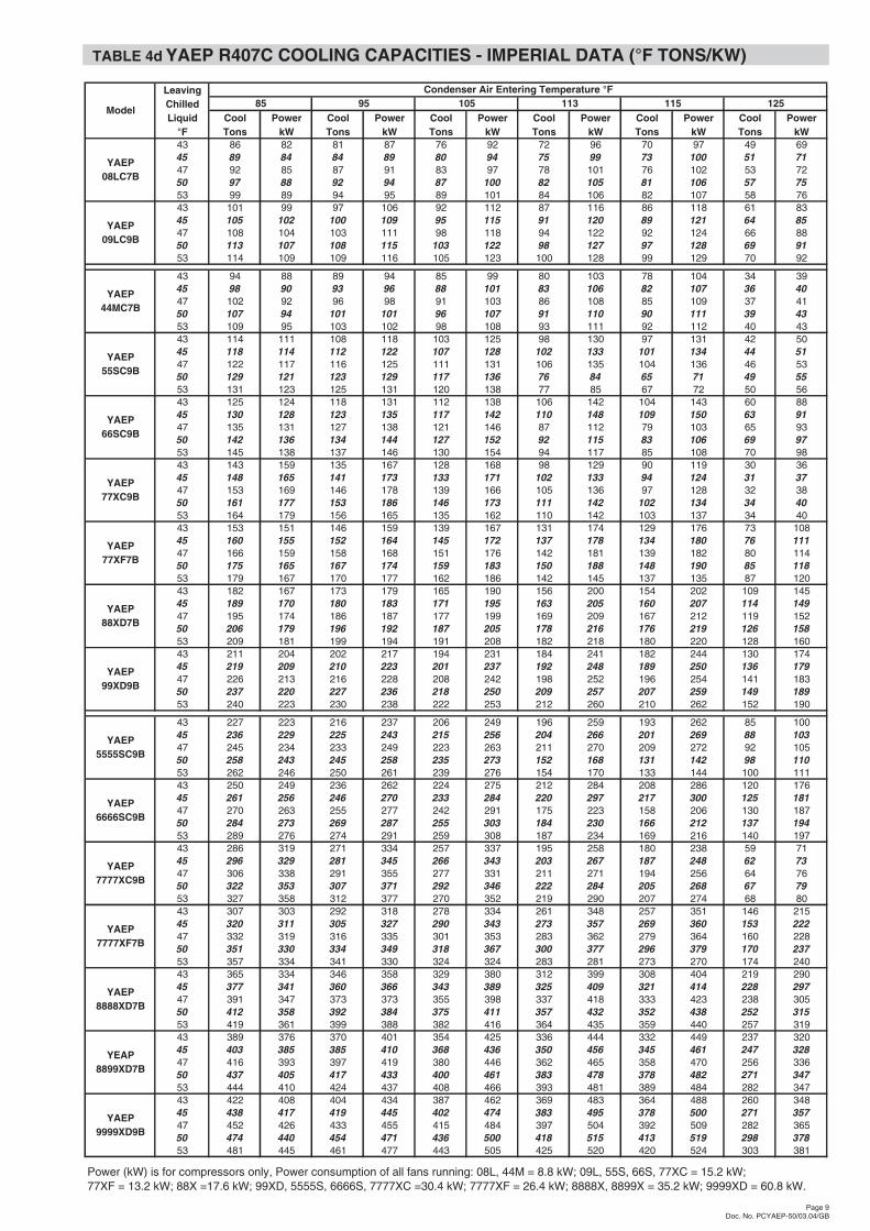
TABLE 4d YAEP R407C COOLING CAPACITIES - IMPERIAL DATA (°F TONS/KW)
Page 9Doc. No. PCYAEP-50/03.04/GB
LeavingChilledLiquid Cool Power Cool Power Cool Power Cool Power Cool Power Cool Power
°F Tons kW Tons kW Tons kW Tons kW Tons kW Tons kW43 86 82 81 87 76 92 72 96 70 97 49 6945 89 84 84 89 80 94 75 99 73 100 51 7147 92 85 87 91 83 97 78 101 76 102 53 7250 97 88 92 94 87 100 82 105 81 106 57 7553 99 89 94 95 89 101 84 106 82 107 58 7643 101 99 97 106 92 112 87 116 86 118 61 8345 105 102 100 109 95 115 91 120 89 121 64 8547 108 104 103 111 98 118 94 122 92 124 66 8850 113 107 108 115 103 122 98 127 97 128 69 9153 114 109 109 116 105 123 100 128 99 129 70 92
43 94 88 89 94 85 99 80 103 78 104 34 3945 98 90 93 96 88 101 83 106 82 107 36 4047 102 92 96 98 91 103 86 108 85 109 37 4150 107 94 101 101 96 107 91 110 90 111 39 4353 109 95 103 102 98 108 93 111 92 112 40 4343 114 111 108 118 103 125 98 130 97 131 42 5045 118 114 112 122 107 128 102 133 101 134 44 5147 122 117 116 125 111 131 106 135 104 136 46 5350 129 121 123 129 117 136 76 84 65 71 49 5553 131 123 125 131 120 138 77 85 67 72 50 5643 125 124 118 131 112 138 106 142 104 143 60 8845 130 128 123 135 117 142 110 148 109 150 63 9147 135 131 127 138 121 146 87 112 79 103 65 9350 142 136 134 144 127 152 92 115 83 106 69 9753 145 138 137 146 130 154 94 117 85 108 70 9843 143 159 135 167 128 168 98 129 90 119 30 3645 148 165 141 173 133 171 102 133 94 124 31 3747 153 169 146 178 139 166 105 136 97 128 32 3850 161 177 153 186 146 173 111 142 102 134 34 4053 164 179 156 165 135 162 110 142 103 137 34 4043 153 151 146 159 139 167 131 174 129 176 73 10845 160 155 152 164 145 172 137 178 134 180 76 11147 166 159 158 168 151 176 142 181 139 182 80 11450 175 165 167 174 159 183 150 188 148 190 85 11853 179 167 170 177 162 186 142 145 137 135 87 12043 182 167 173 179 165 190 156 200 154 202 109 14545 189 170 180 183 171 195 163 205 160 207 114 14947 195 174 186 187 177 199 169 209 167 212 119 15250 206 179 196 192 187 205 178 216 176 219 126 15853 209 181 199 194 191 208 182 218 180 220 128 16043 211 204 202 217 194 231 184 241 182 244 130 17445 219 209 210 223 201 237 192 248 189 250 136 17947 226 213 216 228 208 242 198 252 196 254 141 18350 237 220 227 236 218 250 209 257 207 259 149 18953 240 223 230 238 222 253 212 260 210 262 152 190
43 227 223 216 237 206 249 196 259 193 262 85 10045 236 229 225 243 215 256 204 266 201 269 88 10347 245 234 233 249 223 263 211 270 209 272 92 10550 258 243 245 258 235 273 152 168 131 142 98 11053 262 246 250 261 239 276 154 170 133 144 100 11143 250 249 236 262 224 275 212 284 208 286 120 17645 261 256 246 270 233 284 220 297 217 300 125 18147 270 263 255 277 242 291 175 223 158 206 130 18750 284 273 269 287 255 303 184 230 166 212 137 19453 289 276 274 291 259 308 187 234 169 216 140 19743 286 319 271 334 257 337 195 258 180 238 59 7145 296 329 281 345 266 343 203 267 187 248 62 7347 306 338 291 355 277 331 211 271 194 256 64 7650 322 353 307 371 292 346 222 284 205 268 67 7953 327 358 312 377 270 352 219 290 207 274 68 8043 307 303 292 318 278 334 261 348 257 351 146 21545 320 311 305 327 290 343 273 357 269 360 153 22247 332 319 316 335 301 353 283 362 279 364 160 22850 351 330 334 349 318 367 300 377 296 379 170 23753 357 334 341 330 324 324 283 281 273 270 174 24043 365 334 346 358 329 380 312 399 308 404 219 29045 377 341 360 366 343 389 325 409 321 414 228 29747 391 347 373 373 355 398 337 418 333 423 238 30550 412 358 392 384 375 411 357 432 352 438 252 31553 419 361 399 388 382 416 364 435 359 440 257 31943 389 376 370 401 354 425 336 444 332 449 237 32045 403 385 385 410 368 436 350 456 345 461 247 32847 416 393 397 419 380 446 362 465 358 470 256 33650 437 405 417 433 400 461 383 478 378 482 271 34753 444 410 424 437 408 466 393 481 389 484 282 34743 422 408 404 434 387 462 369 483 364 488 260 34845 438 417 419 445 402 474 383 495 378 500 271 35747 452 426 433 455 415 484 397 504 392 509 282 36550 474 440 454 471 436 500 418 515 413 519 298 37853 481 445 461 477 443 505 425 520 420 524 303 381
77XF = 13.2 kW; 88X =17.6 kW; 99XD, 5555S, 6666S, 7777XC =30.4 kW; 7777XF = 26.4 kW; 8888X, 8899X = 35.2 kW; 9999XD = 60.8 kW.
YAEP66SC9B
YAEP77XC9B
YAEP77XF7B
YAEP88XD7B
YAEP08LC7B
YAEP09LC9B
YAEP44MC7B
YAEP55SC9B
115 125113Condenser Air Entering Temperature °F
Model85 95 105
YAEP99XD9B
YAEP5555SC9B
YAEP6666SC9B
YAEP7777XC9B
Power (kW) is for compressors only, Power consumption of all fans running: 08L, 44M = 8.8 kW; 09L, 55S, 66S, 77XC = 15.2 kW;
YAEP7777XF7B
YAEP8888XD7B
YEAP8899XD7B
YAEP9999XD9B

PHYSICAL DATA - YAEP R22 UNITS TABLE 5a
Page 10Doc. No. PCYAEP-50/03.04/GB
5555SC7C 6666SC9C 7777XC9C 8888XB7C 8899XB7C 9999XD9CUnit Number of Capacity Steps 8 8 8 12 12 12
Number of Compressors 4 4 4 4 4 4
Cylinders per Compressor 4 6 6 8 8 8
Oil Capacity per Compressor l 11 11 11 11 11 11
Coolers per Unit 2 2 2 2 2 2
Cooler Refrigerant Circuits per Cooler 2 2 2 2 2 2
Water Capacity per Cooler l 150 150 205 205 205 205
Condenser Face Area m2 23.8 23.8 23.8 47.6 47.6 47.6
Quantity 8 8 8 16 16 16
Power (each) kW 2.2 3.8 3.8 2.2 2.2 3.8
Total Airflow m3/s 60.8 69.6 69.6 121.6 121.6 139.2
Systems 1/2 kg 49.0 49.0 49.0 57.0 57.0 64.0
Systems 3/4 kg 49.0 49.0 49.0 57.0 57.0 64.0
Ship (Main) kg 4200 4350 4495 5222 5222 5422
Ship (Aux.) kg 4200 4350 4495 5222 5222 5422
Operating kg 8700 9000 9400 10854 10854 11254
Ship (Main) kg 4490 4640 4785 5797 5797 5997
Ship (Aux.) kg 4490 4640 4785 5797 5797 5997
Operating kg 9280 9580 9980 12004 12004 12404
Length mm 6128 6128 6128 11705 11705 11705Width mm 2241 2241 2241 2241 2241 2241Height mm 2466 2466 2466 2466 2466 2466
Weight
Compressor
4 Circuit UnitsYAEP
Refrigerant Charge
Fans
Aluminium Fins
Copper Fins
Dimensions
08LA7C 09LC9C 44MA7C 55SC7C 66SC9C 77XC9C 88XB7C 99XB7C 99XD9CUnit Number of Capacity Steps 3 3 4 4 4 4 6 6 6
Number of Compressors 1 1 2 2 2 2 2 2 2
Cylinders per Compressor 8 8 4 4 6 6 8 8 8
Oil Capacity per Compressor l 11 11 11 11 11 11 11 11 11
Coolers per Unit 1 1 1 1 1 1 1 1 1
Cooler Refrigerant Circuits per Cooler 1 1 2 2 2 2 2 2 2
Water Capacity per Cooler l 90 90 135 150 150 205 205 205 205
Condenser Face Area m2 11.9 11.9 11.9 11.9 11.9 11.9 23.8 23.8 23.8
Quantity 4 4 4 4 4 4 8 8 8
Power (each) kW 2.2 3.8 2.2 2.2 3.8 3.8 2.2 2.2 3.8
Total Airflow m3/s 30.4 34.8 30.4 30.4 34.8 34.8 60.8 60.8 69.6
Systems 1 kg 39.0 42.0 42.0 49.0 49.0 49.0 57.0 57.0 64.0
Systems 2 kg 42.0 49.0 49.0 49.0 57.0 57.0 64.0
Shipping kg 3550 3665 4000 4200 4350 4495 5222 5222 5422
Operating kg 3640 3640 4135 4350 4500 4700 5427 5427 5627
Shipping kg 3740 3955 4190 4490 4640 4785 5797 5797 5997
Operating kg 3830 4045 4325 4640 4790 4990 6002 6002 6202
Length mm 2969 2969 2969 2969 2969 2969 5703 5703 5703
Width mm 2241 2241 2241 2241 2241 2241 2241 2241 2241
Height mm 2466 2466 2466 2466 2466 2466 2466 2466 2466
Refrigerant Charge
Fans
Compressor
1 Circuit UnitsYAEP
2 Circuit Units
Copper Fins
Dimensions
WeightAluminium Fins
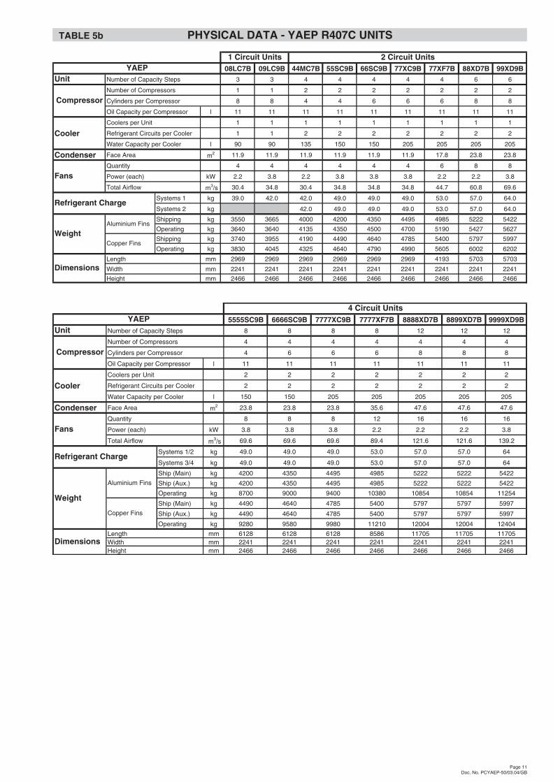
TABLE 5b PHYSICAL DATA - YAEP R407C UNITS
Page 11Doc. No. PCYAEP-50/03.04/GB
5555SC9B 6666SC9B 7777XC9B 7777XF7B 8888XD7B 8899XD7B 9999XD9BUnit Number of Capacity Steps 8 8 8 8 12 12 12
Number of Compressors 4 4 4 4 4 4 4
Cylinders per Compressor 4 6 6 6 8 8 8
Oil Capacity per Compressor l 11 11 11 11 11 11 11
Coolers per Unit 2 2 2 2 2 2 2
Cooler Refrigerant Circuits per Cooler 2 2 2 2 2 2 2
Water Capacity per Cooler l 150 150 205 205 205 205 205
Condenser Face Area m2 23.8 23.8 23.8 35.6 47.6 47.6 47.6
Quantity 8 8 8 12 16 16 16
Power (each) kW 3.8 3.8 3.8 2.2 2.2 2.2 3.8
Total Airflow m3/s 69.6 69.6 69.6 89.4 121.6 121.6 139.2
Systems 1/2 kg 49.0 49.0 49.0 53.0 57.0 57.0 64
Systems 3/4 kg 49.0 49.0 49.0 53.0 57.0 57.0 64
Ship (Main) kg 4200 4350 4495 4985 5222 5222 5422
Ship (Aux.) kg 4200 4350 4495 4985 5222 5222 5422
Operating kg 8700 9000 9400 10380 10854 10854 11254
Ship (Main) kg 4490 4640 4785 5400 5797 5797 5997
Ship (Aux.) kg 4490 4640 4785 5400 5797 5797 5997
Operating kg 9280 9580 9980 11210 12004 12004 12404
Length mm 6128 6128 6128 8586 11705 11705 11705Width mm 2241 2241 2241 2241 2241 2241 2241Height mm 2466 2466 2466 2466 2466 2466 2466
4 Circuit Units
Weight
Aluminium Fins
Copper Fins
Dimensions
Fans
Refrigerant Charge
Compressor
YAEP
08LC7B 09LC9B 44MC7B 55SC9B 66SC9B 77XC9B 77XF7B 88XD7B 99XD9BUnit Number of Capacity Steps 3 3 4 4 4 4 4 6 6
Number of Compressors 1 1 2 2 2 2 2 2 2
Cylinders per Compressor 8 8 4 4 6 6 6 8 8
Oil Capacity per Compressor l 11 11 11 11 11 11 11 11 11
Coolers per Unit 1 1 1 1 1 1 1 1 1
Cooler Refrigerant Circuits per Cooler 1 1 2 2 2 2 2 2 2
Water Capacity per Cooler l 90 90 135 150 150 205 205 205 205
Condenser Face Area m2 11.9 11.9 11.9 11.9 11.9 11.9 17.8 23.8 23.8
Quantity 4 4 4 4 4 4 6 8 8
Power (each) kW 2.2 3.8 2.2 3.8 3.8 3.8 2.2 2.2 3.8
Total Airflow m3/s 30.4 34.8 30.4 34.8 34.8 34.8 44.7 60.8 69.6
Systems 1 kg 39.0 42.0 42.0 49.0 49.0 49.0 53.0 57.0 64.0
Systems 2 kg 42.0 49.0 49.0 49.0 53.0 57.0 64.0
Shipping kg 3550 3665 4000 4200 4350 4495 4985 5222 5422
Operating kg 3640 3640 4135 4350 4500 4700 5190 5427 5627
Shipping kg 3740 3955 4190 4490 4640 4785 5400 5797 5997
Operating kg 3830 4045 4325 4640 4790 4990 5605 6002 6202
Length mm 2969 2969 2969 2969 2969 2969 4193 5703 5703
Width mm 2241 2241 2241 2241 2241 2241 2241 2241 2241
Height mm 2466 2466 2466 2466 2466 2466 2466 2466 2466
Fans
Dimensions
WeightAluminium Fins
Copper Fins
Refrigerant Charge
Compressor
1 Circuit Units 2 Circuit UnitsYAEP

ELECTRICAL DATA - YAEP R22 UNITS TABLE 6a
ELECTRICAL DATA - YAEP R407C UNITS TABLE 6b
Page 12Doc. No. PCYAEP-50/03.04/GB
YAEP Model 35°C/7°CNom. kW Max. kW 380 V 400 V 415 V 342 V 380 V 400 V 415 V 380 V 400 V 415 V
08LA7C 1 101 144 195 194 193 293 268 266 264 689 725 75209LC9C 1 122 150 228 226 224 293 268 266 264 689 725 75244MC7C 2 107 125 197 195 193 275 231 225 221 398 409 420
(55)55SC7C 2/4 137 163 239 237 235 315 289 285 279 500 518 532(66)66SC9C 2/4 149 185 278 276 274 356 336 332 328 626 648 674(77)77XC9C 2/4 189 227 348 344 342 422 408 404 400 753 780 802(88)88XB7C 2/4 228 300 410 408 406 580 530 526 522 954 988 1015
99XB7C 2 270 300 480 470 466 580 530 526 522 954 988 1015228 300 410 408 406 580 530 526 522 954 988 1015270 300 480 470 466 580 530 526 522 954 988 1015
(99)99XD9C 2/4 250 300 469 463 461 595 545 541 537 961 995 1020
YAEP Model 35°C/7°CNom. kW Max. kW 380 V 400 V 415 V 342 V 380 V 400 V 415 V 380 V 400 V 415 V
44MC7C 2 53 62 98 97 96 137 115 112 110 283 297 30855SC7C 2 69 82 119 118 117 157 144 142 139 356 376 39066SC9C 2 75 93 139 138 137 178 168 166 164 458 482 50877XC9C 2 95 114 174 172 171 211 204 202 200 549 578 60088XB7C 2 114 150 205 204 203 290 265 263 261 689 725 75299XB7C 2 135 150 240 235 233 290 265 263 261 689 725 75299XD9C 2 125 150 234 231 230 297 272 270 268 689 725 752
5555SC7C 4 65 82 119 118 117 157 144 142 139 356 376 3906666SC9C 4 71 93 139 138 137 178 168 166 164 458 482 5087777XC9C 4 91 114 174 172 171 211 204 202 200 549 578 6008888XB7C 4 114 150 205 204 203 290 265 263 261 689 725 752
8899XB7C Main 2 114 150 205 204 203 290 265 263 261 689 725 7528899XB7C Aux 2 135 150 240 235 233 290 265 263 261 689 725 752
9999XD9C 4 125 150 234 227 230 297 272 270 268 689 725 752
Power Requirement per Panel - 1, 2 and 4 Refrigerant Circuit Units with Single Point Power Supply - Disconnect Switch (CE) or Terminal Block Option (Non CE)(Data includes one/both compressors and associated fans)
Note: To obtain the total unit power requirements on four circuit models 5555SC7C / 6666SC9C / 7777XC9C / 8888XB7C / 9999XD9C multiply the panel values by 2.
Note: To obtain the total unit power requirements on four circuit model 8899XB7C the panel values should be added together.
Nominal. Amps Maximum. Amp Part Wind Inrush
Nominal. Amps Maximum. Amp Part Wind Inrush
Power Requirement per Refrigeration Circuit - 2 and 4 Refrigerant Circuit Units with Multi Point Power Supply Option (Non CE)(Data includes each circuit compressor and associated fans)
Circuits
Circuits
8899XB7C 2+2
YAEP Model 35°C/7°CNom. kW Max. kW 380 V 400 V 415 V 342 V 380 V 400 V 415 V 380 V 400 V 415 V
08LC7B 1 97 144 190 189 188 293 268 266 264 689 725 75209LC9B 1 123 150 228 226 224 293 268 266 264 689 725 75244MC7B 2 105 125 197 195 193 275 231 225 221 398 409 418
(55)55SC9B 2/4 137 163 246 244 242 322 296 292 286 504 522 533(66)66SC9B 2/4 149 185 280 278 276 356 336 332 328 626 648 672(77)77XC9B 2/4 187 227 348 346 342 422 412 406 400 755 781 800(77)77XF7B 2/4 177 225 331 329 327 427 417 411 405 758 784 803(88)88XB7B 2/4 200 288 386 380 374 580 530 526 522 954 988 1013
200 288 386 380 446 580 530 526 522 954 988 1013244 288 450 448 446 580 530 526 522 954 988 1013
(99)99XD9B 2/4 250 300 457 455 453 595 545 541 537 961 995 1020
YAEP Model 35°C/7°CNom. kW Max. kW 380 V 400 V 415 V 342 V 380 V 400 V 415 V 380 V 400 V 415 V
44MC7B 2 52 62 98 97 96 137 115 112 110 283 297 30855SC9B 2 69 82 123 122 121 161 148 146 143 356 376 39066SC9B 2 75 93 140 139 138 178 168 166 164 458 482 50877XC9B 2 94 114 174 173 171 211 206 203 200 549 578 60077XF7B 2 89 113 166 165 164 214 209 206 203 549 578 60088XB7B 2 100 144 193 190 187 290 265 263 261 689 725 75299XD9B 2 125 150 228 227 226 297 272 270 268 689 725 752
5555SC9B 4 65 82 123 122 121 161 148 146 143 356 376 3906666SC9B 4 71 93 140 139 138 178 168 166 164 458 482 5087777XC9B 4 90 114 174 173 171 211 206 203 200 549 578 6007777XF7B 4 91 113 166 165 164 214 209 206 203 549 578 6008888XB7B 4 100 144 193 190 187 290 265 263 261 689 725 752
8899XB7B Main 2 100 144 193 190 187 290 265 263 261 689 725 7528899XB7B Aux 2 122 144 225 224 223 290 265 263 261 689 725 752
9999XD9B 4 125 150 228 227 226 297 272 270 268 689 725 752
Power Requirement per Panel - 1, 2 and 4 Refrigerant Circuit Units with Single Point Power Supply - Disconnect Switch (CE) or Terminal Block Option (Non CE)(Data includes one/both compressors and associated fans)
Note: To obtain the total unit power requirements on four circuit models 5555SC9B / 6666SC9B / 7777XC9B / 7777XF7B / 8888XB7B / 9999XD9B multiply the panel values by 2.
Note: To obtain the total unit power requirements on four circuit model 8899XB7B the panel values should be added together.
Nominal. Amps Maximum. Amp Part Wind Inrush
Nominal. Amps Maximum. Amp Part Wind Inrush
Power Requirement per Refrigeration Circuit - 2 and 4 Refrigerant Circuit Units with Multi Point Power Supply Option (Non CE)(Data includes each circuit compressor and associated fans)
Circuits
(88)99XB7B
Circuits
2+2

Page 13Doc. No. PCYAEP-50/03.04/GB
POWER SUPPLY CONNECTIONS
(Main Panel and Auxiliary Panel when fitted)
1 PS 2 PS
QCSITB
3 50 Hz 380/400 V
PE
PE
U V W
L1 L2 L3
3 4
QRESB
Single Point Power Supply (Non CE) Optionommon terminal block (QCSITB) with
internal power distribution to fuses,One supply per panel to a c
control supply to non-fuseddisconnect switch (QCSD/ESD) derived internally.
CIS
1 PS 2 PS
QCSISD
3 50 Hz 380/400 V
PE
PE
U V W
L1 L2 L3
3 4
QRESB
Standard Single Point Power Supply (CE)
fuses,One supply per panel to master non-fused disconnect switch(XCSISD) with internal power distribution to control supplyto non-fused disconnect switch (QCSD/ESD) derived internally.
CIS COMMON INPUT SECTION
PE PROTECTIVE EARTHF FUSE
PS POWER SECTIONQCSD/ESD CONTROL CIRCUIT SWITCH DISCONNECT
/ EMERGENCY STOP DEVICEQCSISD COMMON SUPPLY INPUT SWITCH DISCONNECTQCSITB COMMON SUPPLY INPUT TERMINAL BLOCKQRESB REMOTE EMERGENCY STOP BUTTON
ARB RELAY BOARD
CIS
AMB MICROPROCESSOR BOARD
CS CONTROL SECTION
1 PS 2 PS
3 50Hz380/400V
PE
PE
U V W
L1 L2 L3
3 50Hz380/400V
U
PE
PE
V W
L3L2L1
CompressorContactor
PE
380/400V2 50Hz
PEL3L1
QCSD/ESD
34
QRESB
Multi Point Power Supply (Non CE) OptionsOne supply per refrigerant circuit to fuse/terminal blockwith separate control supply to non-fused disconnectswitch (QCSD/ESD).
CIS
CS
AMB ARB
AP
B
APB POWER SUPPLY BOARD
CompressorContactor
F F F F F F
F F F F F F
Common InputSection
Non-FusedDisconnect Switchor Terminal Block
ProtectiveEarth
Control Circuit SwitchDisconnect / Emergency
Stop Device
DESIGNATION DESCRIPTION
System Fuses,or Terminal Block
Power Section
ProtectiveEarth
ControlSection
PowerSection 2
CommonInput
Section
PowerSection 1
YAEP 44M-77X & 5555S-7777X
PowerSection 2
ControlSection
CommonInput
Section
PowerSection 1
YAEP 88X-99X & 8888X-9999X
YAEP 08L-09L
PowerSection 1
ControlSection
CommonInput
Section

CONTROL CONNECTIONS(Main Panel and Auxiliary Panel when fitted)
Page 14Doc. No. PCYAEP-50/03.04/GB
AMB
APB
ARB
13 10 11 14 12 15 16 13 17 18 1310
Unit Run Signal
32
31
30
39
37
35
38
Chilled Liquid Pump Start
Close on Alarm
SystemNo. 1 / 3
Open on Alarm }
}}
}}}
}
36
33
34
Close on Alarm
SystemNo. 2 / 4
Open on Alarm }
Note 1
Note 1: Fit link between terminals 14 and 15 and connect a voltage free contact to terminals 11 and 14for combined Remote Start/Stop of systems 1 / 2 (2 circuit units) and systems 3 / 4 (4 circuit units).
System No. 1 / 3 Remote Start/Stop
System No. 2 / 4 Remote Start/Stop
Remote Setpoint Reset (Main Panel only)
Remote Unload
Chilled Liquid Flow Switch
Remote Print (Main Panel only)
Remote Lead/Lag
Mixed WaterTemperature
(4 Circuit Units Only)
BLA
CK
WH
ITE
MAINPANEL
AUXILIARYPANEL
Communication Link(4 Circuit Units Only)
Communications Link Cableto be field run andconnected to Main Panel TB7during installation
CIS COMMON INPUT SECTIONPS POWER SECTION
ARB RELAY BOARD
AMB MICROPROCESSOR BOARD
CS CONTROL SECTION
APB POWER SUPPLY BOARD
DESIGNATION DESCRIPTION
Control Section
ControlSection
PowerSection 2
CommonInput
Section
PowerSection 1
YAEP 44M-77X & 5555S-7777X
PowerSection 2
ControlSection
CommonInput
Section
PowerSection 1
YAEP 88X-99X & 8888X-9999XYAEP 08L-09L
PowerSection 1
ControlSection
CommonInput
Section

DIMENSIONS YAEP 08L & 09L
Page 15Doc. No. PCYAEP-50/03.04/GB
2969
2172
AV
MP
OS
ITIO
NS
148
446
520
8401990
2241
946
2897
1778
500
1911
AV
MC L
493
AV
M335
24666"
(150
mm
)O
utle
t6"
(150
mm
)In
let

DIMENSIONS YAEP 44M - 77XC
Page 16Doc. No. PCYAEP-50/03.04/GB
2466.4
493
2241
449
1911
2108
(216
0on
44M
)
2897
407(382on44Mand446on77XC)
2172
AV
MP
OS
ITIO
NS
702
2969
340
(314
on44
M)
8"(2
00m
m)
(6"
(150
mm
)on
44M
)O
utle
t
8"(2
00m
m)
(6"
(150
mm
)on
44M
)In
let

DIMENSIONS YAEP 77XF
Page 17Doc. No. PCYAEP-50/03.04/GB
2241
493
702
2166
AV
MP
OS
NS
.
446
1707
AV
MP
OS
NS
.16
76A
VM
PO
SN
S.
2108
1631
4187
4250
2467 312
8"(2
00m
m)
Out
let
8"(2
00m
m)
Inle
t

DIMENSIONS YAEP 88X - 99X
Page 18Doc. No. PCYAEP-50/03.04/GB
2426
199
AV
M24
38A
VM
PO
SIT
ION
S
40 446
2108
634
5407
1220
AV
M12
57A
VM
292
AV
M
8381153
124
221
5700
1800
702
2241C
OM
PR
ES
SO
RS
YS
TE
M2
SY
ST
EM
1C
OM
PR
ES
SO
RR
EM
OV
ED
FO
R D
RA
WIN
GC
LAR
ITY
2166
AV
MP
OS
ITIO
NS
8"(2
00m
m)
Out
let
8"(2
00m
m)
Inle
t

DIMENSIONS YAEP 5555S - 7777XC
Page 19Doc. No. PCYAEP-50/03.04/GB
1911
AV
MP
OS
.
2466
2897
2108
1911
AV
MP
OS
.
2897
2108
493
340
300
493
340
2172
AV
MP
OS
ITIO
NS
406(446on7777XC)
2241
6232
8401150
8"(2
00m
m)
Out
let
8"(2
00m
m)
Inle
t8"
(200
mm
)In
let
8"(2
00m
m)
Out
let

DIMENSIONS YAEP 7777XF
Page 20Doc. No. PCYAEP-50/03.04/GB
2241
702
2172
2108
1631
1676
4187
1707
312
8675
1631
2108
312
1676
1707
4187
493
2467
446
8812
300
8"(2
00m
m)
Inle
t8"
(200
mm
)O
utle
t8"
(200
mm
)O
utle
t8"
(200
mm
)In
let

DIMENSIONS YAEP 8888X - 9999X
Page 21Doc. No. PCYAEP-50/03.04/GB
2426 29229
240 446
1257
AV
M12
20A
VM
2664
5407
2108
2438
AV
MP
OS
ITIO
NS
699
1568
RE
F.
1257
AV
M
292
292
1153 838
702
2241CO
MP
RE
SS
OR
SY
ST
EM
2,3
1800 221
MU
LTIP
OIN
TC
AB
LEE
NT
RY
SY
ST
EM
3
SIN
GL
PO
INT
CA
BLE
EN
TR
YS
YS
TE
MS
3&
4
MU
LTI P
OIN
TC
AB
LEE
NT
RY
SY
ST
EM
4
1170
0
MU
LTI P
OIN
TC
AB
LEE
NT
RY
SY
ST
EM
2
SIN
GL
PO
INT
CA
BLE
EN
TR
YS
YS
TE
MS
1&
2
MU
LTI P
OIN
TC
AB
LEE
NT
RY
SY
ST
EM
1
300
Not
e:D
IME
NS
ION
SA
ND
AV
MP
OS
ITIO
NS
AR
EID
EN
TIC
AL
FO
R B
OT
H S
EC
TIO
NS
-R
EF
ER
TOO
TH
ER
SE
CT
ION
FO
R D
ETA
ILS
5407
SY
ST
EM
1an
d4
CO
MP
RE
SS
OR
SR
EM
OV
ED
FO
R D
RA
WIN
GC
LAR
ITY
2166
AV
MP
OS
ITIO
NS
8"(2
00m
m)
Inle
t8"
(200
mm
)O
utle
t

Subject to change without notice. ALL RIGHTS RESERVED
YORK
EMEAYORK INTERNATIONALGardiners Lane South, Basildon, Essex SS14 3HE, England
GB