york retail system specific wiring diagrams - … retail diagrams 2012 w...york retail system...
TRANSCRIPT

York Retail System SpecificWiring Diagrams
January 2012
Using Honeywell Thermostats

IndoorYZH AVG or MVYZH AVG or MVYZH YP9CYZH YP9CYZH TM9X or 8XYZH TM9X & 8XYZF 1.5-4 Ton AVG or MVYZF 1.5-4 Ton AVG or MVYZF 1.5-4 Ton AHE YZF 1.5-4 Ton MXYZF 1.5-4 Ton TM9V or 8VYZF 5-Ton AVG or MVYZF 5-Ton AVG or MVYZF 5-Ton AHE YZF 5-Ton MXYZF 5 Ton TM9V or 8VYZF 1.5-4 Ton TM9X or 8XYZF 1.5-4 Ton TM9X & 8XYZF 5- Ton TM9X or 8XYZF 5 Ton TM9X & 8XYZF 1.5-4 Ton TG9S or 8SYZF 1.5-4 Ton TG9S or 8SCZH AVG or MVCZH AVG or MVCZH YP9CCZH YP9CCZH TM9V or 8VCZH TM9V or 8VCZH TM9X or 8XCZH TG9S or 8SCZF AVG or MVCZF AVG or MVCZF AHE CZF MXCZF TM9V or 8VCZF TM9V or 8VCZF TM9X or 8XCZF TG9S or 8SCZF TG9S or 8S
WD20
1 Stage HP 95% & 80% Single Stage X13 Gas Furnace HW VP 9000 WD182 Stage HP 95% & 80%Single Stage X13 Gas Furnace HW VP 8000 WD192 Stage HP
1 Stage HP1 Stage HP WD7
2 Stage HP Variable Speed Air Handler X13 Motor Honeywell VP 8000
Variable Speed Air Handler Honeywell VP 8000
WD11
WD14
Index for Low Voltage Wiring Affinity Units
Outdoor System Description Page
2 Stage HP 95% Modulating VS Gas Furnace - Honeywell VP 8000
WD5
WD3
2 Stage HP Variable Speed Air Handler - Honeywell VP 8000 WD1
WD4
2 Stage HP 95% & 80% 1 Stage Multi-Tap Gas Furnace HW VP 9000
2 Stage HP Variable Speed Air Handler - Honeywell VP 9000 WD2
2 Stage HPWD6
2 Stage HP 95% Modulating VS Gas Furnace - Honeywell VP 900095% & 80% 1 Stage Multi-Tap Gas Furnace HW VP 8000
WD32
Variable Speed Air Handler Honeywell VP 9000
1 Stage HP 95% & 80%Single Stage X13 Gas Furnace HW VP 8000 WD17
WD8
95% & 80% 2 Stage Variable Speed Gas Furnace HW VP 8000
2 Stage HP 95% & 80% 2 Stage Variable Speed Gas Furnace HW VP 8000 WD16
2 Stage AC Variable Speed Air Handler Honeywell VP8000
1 Stage AC
1 Stage AC 95% & 80% 1Stage Multi-Tap Gas Furnace HW VP 8000 WD38
2 Stage AC
1 Stage AC Variable Speed Air Handler Honeywell VP 8000
2 Stage AC
95% & 80% 1 Stage Multi-Tap Gas Furnace HW FP 5000 WD21
95% & 80%Single Stage X13 Gas Furnace HW VP 8000 WD30
95% & 80% 1Stage Multi-Tap Gas Furnace HW VP 8000 WD3795% & 80% 2 Stage Variable Speed Gas Furnace HW VP 9000
Variable Speed Air Handler X13 Motor Honeywell VP 80001 Stage AC Variable Speed Air Handler Honeywell VP 9000
95% & 80% 1 Stage Multi-Tap Gas Furnace HW VP 90001 Stage AC WD39
1 Stage AC1 Stage AC
1 Stage ACWD33
HONEYWELL ZONING CONTROLS
WD36
WD23
WD3595% & 80% 2 Stage Variable Speed Gas Furnace HW VP 80001 Stage AC
2 Stage ACWD29
WD31
Variable Speed Air Handler X13 Motor Honeywell VP 80001 Stage HP
To be determined
2 Stage AC 95% Modulating Variable Speed Gas Furnace HW VP8000 WD25
95% & 80% Single Stage X13 Gas Furnace HW VP 9000
95% & 80% 1Stage Multi-Tap Gas Furnace HW VP 8000
1 Stage HP Variable Speed Air Handler X13 Motor Honeywell VP 8000 WD9
2 Stage HP Variable Speed Air Handler Honeywell VP 9000 WD13
1 Stage HPWD10
95% & 80% 2 Stage Variable Speed Gas Furnace HW VP 8000 WD27
Variable Speed Air Handler Honeywell VP9000 WD24
1 Stage HP
2 Stage HP Variable Speed Air Handler Honeywell VP 8000 WD12
1 Stage HP WD22
2 Stage AC2 Stage AC 95% & 80% 2 Stage Variable Speed Gas Furnace HW VP 9000 WD28
95% & 80%Single Stage X13 Gas Furnace HW VP 8000
Variable Speed Air Handler X13 Motor Honeywell VP 8000 WD34
2 Stage HP Variable Speed Air Handler X13 Motor Honeywell VP 8000 WD15
2 Stage AC 95% Modulating Variable Speed Gas Furnace HW VP9000 WD26

YHJF 1.5-4 Ton AHEYHJF 1.5-4 Ton MXYHJF 1.5-4 Ton TM9V or 8VYHJF 1.5-4 Ton TM9X or 8XYHJF 5 Ton TM9V or 8VYHJF 5 Ton TM9X or 8XYHJD AHEYHJD MXYHJD TM9X or 8XYHJR TG9S or 8SYCJF TM9X or 8XYCJD TM9X or 8X
R - Hot side of 24 volt transformerC - Common side of 24 volt transformerY - Cooling or heating call on single stage unitsY1 - 1st stage cooling or heating call Y2 - 2nd stage cooling or heating callY/Y2 - Used to get full indoor unit CFMW - Heating call on single stage furnacesO - Energize the reversing valve to get coolingG - Energize the blowerW1 - 1st stage heating callW2 - 2nd stage heating callY2 Out - Used to energize the indoor cfm to high speedW1 Out - Output to energize 1st stage heat when in defrostW2 Out - Output to energize 2nd stage heat when in defrostW1/66 - Used to energize 1st stage heat when in defrostBSG & BS - Terminals on the defrost control to connect bonnet sensor in the duel fuel modeHum - Humidistat inputDHUM - Used to slow the indoor blower in high humidity applicationsLo Comp - Used on modulating furnaces when there is a single stage thermostat for coolingHi Comp - Used on modulating furnaces when there is a single stage thermostat for cooling
WD50WD51
Variable Speed Air Handler X13 Motor Honeywell VP 8000
2 Stage HP
1 Stage HP WD49
1 Stage HP Variable Speed Air Handler X13 Motor Honeywell VP 8000
1 Stage HP Variable Speed Air Handler X13 Motor Honeywell VP 8000 WD47
1 Stage HP 95% & 80% 2 Stage Variable Speed Gas Furnace HW VP 80001 Stage HP
1 Stage AC 95% & 80% 1 Stage Multi-Tap Gas Furnace HW VP 8000
WD46
WD48
1 Stage AC
1 Stage HP 95% & 80% 1 Stage Multi-Tap Gas Furnace HW VP 8000
95% & 80% 1 Stage Multi-Tap Gas Furnace HW VP 8000
WD40WD41
Index for Low Voltage Wiring LX Units
WD442 Stage HP 95% & 80% 1 Stage Multi-Tap Gas Furnace HW VP 8000 WD45
Variable Speed Air Handler X13 Motor Honeywell VP 8000
95% & 80% 1 Stage Multi-Tap Gas Furnace HW VP 8000
WD42WD43
95% & 80% 2 Stage Variable Speed Gas Furnace HW VP 8000
A Brief Description of Low Voltage Terminals used on York units.
95% & 80% 1 Stage Multi-Tap Gas Furnace HW VP 8000
1 Stage HP
1 Stage HP
York SystemWiring Diagram
WD 1
Optional
Optional
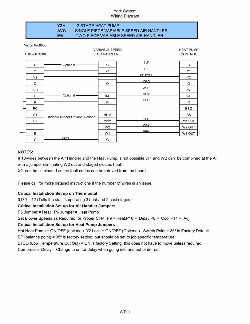
NOTES:If 10-wires between the Air Handler and the Heat Pump is not possible W1 and W2 can be combined at the AHwith a jumper eliminating W2 out and staged electric heat. X/L can be eliminated as the fault codes can be retrived from the board.
Please call for more detailed instructions if the number of wires is an issue.
Critical Installation Set up on Thermostat0170 = 12 (Tells the stat its operating 3 heat and 2 cool stages)Critical Installation Set up for Air Handler JumpersP5 Jumper = Heat P6 Jumper = Heat Pump Set Blower Speeds as Required for Proper CFM. P9 = Heat,P10 = Delay,P8 = Cool,P11 = Adj.Critical Installation Set up for Heat Pump JumpersHot Heat Pump = ON/OFF (optional) Y2 Lock = ON/OFF (Optional) Switch Point = 35º is Factory DefaultBP (balance point) = 35º is factory setting, but should be set to job specific temperature LTCO (Low Temperature Cut Out) = ON is factory Setting, this does not have to move unless requiredCompressor Delay = Change to on for delay when going into and out of defrost
G G
W2 W2 OUT
E W1 W1 OUT
S1 Indoor/Outdoor Optional Sensor HUM BS
S2 Y2/Y Y2 OUT
R R R
RC BSG
Aux W
L X/L X/L
Y2 Y2
O O O
C C C
Y Y1 Y1
YZH 2-STAGE HEAT PUMPAVG SINGLE PIECE VARIABLE SPEED AIR HANDLERMV TWO PIECE VARIABLE SPEED AIR HANDLER
Vision Pro8000
TH8321U1006VARIABLE SPEED HEAT PUMP
AIR HANDLER CONTROL
BLK
YEL
BLU/YEL
ORG
WHT
PUR
RED
BLU
GRY
BRN
GRN

York SystemWiring Diagrams
WD 2
IAQ 9000
NOTES:If 10-wires between the Air Handler and the Heat Pump is not possible W1 and W2 can be combined at the AHwith a jumper eliminating W2 out and staged electric heat. X/L can be eliminated as the fault codes can be retrived from the board.
Please call for more detailed instructions if the number of wires is an issue.
Critical Installation Set up on Thermostat#172, CHANGE TO 2 (tells stat the system in a Heat Pump)#174, CHANGE TO 2 (tells stat number of cooling stages)#176, CHANGE TO 3 (tells stat number of heating stages)#200, CHANGE TO 0 (tells stat back up heat is electric)Critical Installation Set up for Air Handler JumpersP5 Jumper = Heat P6 Jumper = Heat Pump Set Blower Speeds as Required for Proper CFM. P9 = Heat,P10 = Delay,P8 = Cool,P11 = Adj.Critical Installation Set up for Heat Pump JumpersHot Heat Pump = ON/OFF (optional) Y2 Lock = ON/OFF (Optional) Switch Point = 35º is Factory DefaultBP (balance point) = 35º is factory setting, but should be set to job specific temperature LTCO (Low Temperature Cut Out) = ON is factory Setting, this does not have to move unless requiredCompressor Delay = Change to on for delay when going into and out of defrost
Aux 2 W1 W1 OUT
G G
Y2/Y Y2 OUT
W2 W2 OUT
RC BSG
RH HUM BS
L X/L X/L
R R R
O O O
AUX W
Y Y1 Y1
Y2 Y2
1
2
3
C C C
YZH 2-STAGE HEAT PUMPAVG SINGLE PIECE VARIABLE SPEED AIR HANDLERMV TWO PIECE VARIABLE SPEED AIR HANDLERHONEYWELL 9000 IAQ THERMOSTAT
TO THERMOSTAT
YTH9421C1002VARIABLE SPEED HEAT PUMP
AIR HANDLER CONTROL
BLK
YEL
BLU/YEL
ORG
WHT
PUR
RED
BLU
GRY
BRN
GRN
York SystemWiring Diagrams
WD 3
Optional
Optional
*
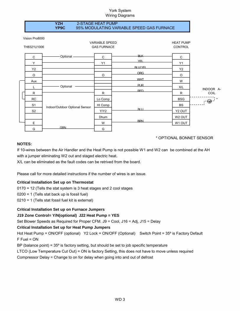
* OPTIONAL BONNET SENSORNOTES:If 10-wires between the Air Handler and the Heat Pump is not possible W1 and W2 can be combined at the AHwith a jumper eliminating W2 out and staged electric heat. X/L can be eliminated as the fault codes can be retrived from the board.
Please call for more detailed instructions if the number of wires is an issue.
Critical Installation Set up on Thermostat0170 = 12 (Tells the stat system is 3 heat stages and 2 cool stages0200 = 1 (Tells stat back up is fossil fuel)0210 = 1 (Tells stat fossil fuel kit is external)
Critical Installation Set up on Furnace JumpersJ19 Zone Control= Y/N(optional) J22 Heat Pump = YESSet Blower Speeds as Required for Proper CFM. J9 = Cool, J16 = Adj, J15 = DelayCritical Installation Set up for Heat Pump JumpersHot Heat Pump = ON/OFF (optional) Y2 Lock = ON/OFF (Optional) Switch Point = 35º is Factory DefaultF Fuel = ON BP (balance point) = 35º is factory setting, but should be set to job specific temperature LTCO (Low Temperature Cut Out) = ON is factory Setting, this does not have to move unless requiredCompressor Delay = Change to on for delay when going into and out of defrost
G G
Dhum W2 OUT
E W W1 OUT
S1 Indoor/Outdoor Optional Sensor HI Comp BS
S2 Y/Y2 Y2 OUT
INDOOR A-COILR R R
RC Lo Comp BSG
Aux W
L X/L
Y2 Y2
O O O
C C C
Y Y1 Y1
YZH 2-STAGE HEAT PUMPYP9C 95% MODULATING VARIABLE SPEED GAS FURNACE
Vision Pro8000
TH8321U1006VARIABLE SPEED HEAT PUMP
GAS FURNACE CONTROL
BLK
YEL
BLU/YEL
ORG
WHT
PUR
RED
BLU
BRN
GRN

York SystemWiring Diagrams
WD 4
Optional
Optional
*
* OPTIONAL BONNET SENSORNOTES:If 10-wires between the Air Handler and the Heat Pump is not possible W1 and W2 can be combined at the AHwith a jumper eliminating W2 out and staged electric heat. X/L can be eliminated as the fault codes can be retrived from the board.
Please call for more detailed instructions if the number of wires is an issue.
Critical Installation Set up on Thermostat#172, CHANGE TO 2 (tells stat the system in a Heat Pump)#174, CHANGE TO 2 (tells stat number of cooling stages)#176, CHANGE TO 3 (tells stat number of heating stages)#200, CHANGE TO 1 (tells stat back up heat is electric)#210, CHANGE TO 1 (tells stat external fossil fuel kit)Critical Installation Set up on Furnace JumpersJ9=Zone Control = Y/N (optional) J22=Heat Pump = YES Set Blower Speeds as Required for Proper CFM. J9 = Cool, J16 = Adj, J15 = DelayCritical Installation Set up for Heat Pump JumpersHot Heat Pump = ON/OFF (optional) Y2 Lock = ON/OFF (Optional) Switch Point = 35º is Factory DefaultF Fuel = ON BP (balance point) = 35º is factory setting, but should be set to job specific temperature LTCO (Low Temperature Cut Out) = ON is factory Setting, this does not have to move unless requiredCompressor Delay = Change to on for delay when going into and out of defrost
G G
HI Comp
Y2
S1
TO THERMOSTAT
Dhum
Aux
C C
W2 OUT
E W W1 OUT
BS
S2 Y/Y2 Y2 OUT
INDOOR A-COILR R R
RC Lo Comp BSG
W
L X/L
Y2
O O O
YZH 2-STAGE HEAT PUMPYP9C 95% MODULATING VARIABLE SPEED GAS FURNACE
YTH9421C1002VARIABLE SPEED HEAT PUMP
GAS FURNACE CONTROL
Honeywell 9000 IAQ Thermostat
IAQ 9000
C
Y Y1 Y1
1
2
3BLK
YEL
BLU/YEL
ORG
WHT
PUR
RED
BLU
BRN
GRN

York SystemWiring Diagrams
WD 5
* OPTIONAL BONNET SENSOR
NOTES:If 10-wires between the Air Handler and the Heat Pump is not possible W1 and W2 can be combined at the AHwith a jumper eliminating W2 out and staged electric heat. X/L can be eliminated as the fault codes can be retrived from the board.
Please call for more detailed instructions if the number of wires is an issue.
Critical Installation Set up on Thermostat0170 = 12 (Tells the stat system is 3 heat stages and 2 cool stages0200 = 1 (Tells stat back up is fossil fuel)0210 = 1 (Tells stat fossil fuel kit is external)
Critical Installation Set up on Furnace JumpersP4 Jumper = Blower Off Delay P7 Jumper = Fan Speed Contionus FanSet motor speeds as required for proper air flow
Critical Installation Set up for Heat Pump JumpersHot Heat Pump = ON/OFF (optional) Y2 Lock = ON/OFF (Optional) Switch Point = 35º is Factory DefaultBP (balance point) = 35º is factory setting, but should be set to job specific temperature LTCO (Low Temperature Cut Out) = ON is factory Setting, this does not have to move unless requiredCompressor Delay = Change to on for delay when going into and out of defrost
E W W1 OUT
G G
S2 Y2/Y Y2 OUT
R R R
W2 OUT
RC BSG
S1 BS
AUX W
L X/L
Y2 Y2
O O
Gas Furnace CONTROL
C C C
Y Y1 Y1
Vision Pro8000
INDOOR A-COIL
Indoor/Outdoor Optional Sensor
YZH 2-STAGE HEAT PUMPTM9X Gas Furnace
TM8X Gas Furnace
TH8321U1006TM9X HEAT PUMP
BLK
YEL
BLU/YEL
ORG
WHTPUR - Optional
RED
BLU
GRY
BRN
GRN

York SystemWiring Disgrams
WD 6
IAQ 9000
NOTES:If 10-wires between the Air Handler and the Heat Pump is not possible W1 and W2 can be combined at the AHwith a jumper eliminating W2 out and staged electric heat. X/L can be eliminated as the fault codes can be retrived from the board.
Please call for more detailed instructions if the number of wires is an issue.
Critical Installation Set up on Thermostat#172, CHANGE TO 2 (tells stat the system in a Heat Pump)#174, CHANGE TO 2 (tells stat number of cooling stages)#176, CHANGE TO 3 (tells stat number of heating stages)#200, CHANGE TO 1 (tells stat back up heat is fossil fuel)#210, CHANGE TO 1 (tells stat fossil fuel is controlled external)Critical Installation Set up for Furnace JumpersP4 Jumper = Blower Off Delay P7 Jumper = Fan Speed Contionus FanSet motor speeds as required for proper air flowCritical Installation Set up for Heat Pump JumpersHot Heat Pump = ON/OFF (optional) Y2 Lock = ON/OFF (Optional) Switch Point = 35º is Factory DefaultBP (balance point) = 35º is factory setting, but should be set to job specific temperature LTCO (Low Temperature Cut Out) = ON is factory Setting, this does not have to move unless requiredCompressor Delay = Change to on for delay when going into and out of defrost
Aux 2 W W1 OUT
G G
TM8X Gas Furnace
Y2/Y Y2 OUT
W2 OUT
RC BSG
RH BS
L X/L
R R R
O O
AUX W
Y Y1 Y1
Y2 Y2
CONTROL
1
2
3
C C C
INDOOR A-COIL
YZH 2-STAGE HEAT PUMPTM9X Gas Furnace
HONEYWELL 9000 IAQ THERMOSTAT
TO THERMOSTAT
YTH9421C1002TM9X HEAT PUMP
Gas Furnace
BLK
YEL
BLU/YEL
ORG
WHTPUR - Optional
RED
BLU
BRN
GRN

York SystemWiring Diagrams
WD 7
Optional
Optional
NOTES:If 10-wires between the Air Handler and the Heat Pump is not possible W1 and W2 can be combined at the AHwith a jumper eliminating W2 out and staged electric heat. X/L can be eliminated as the fault codes can be retrived from the board.
Please call for more detailed instructions if the number of wires is an issue.
Critical Installation Set up on Thermostat0170 = 7 (tells the stat it's operating at 2 heat and 1 cool stage as a heat pump)
Critical Installation Set up for Air Handler JumpersP5 Jumper = Heat P6 Jumper = Heat Pump Set Blower Speeds as Required for Proper CFMSet Blower Speeds as Required for Proper CFM. P9 = Heat,P10 = Delay,P8 = Cool,P11 = Adj.Critical Installation Set up for Heat Pump JumpersHot Heat Pump = ON/OFF (optional) Y2 Lock = ON/OFF (Optional)BP (balance point) = 35º is factory setting, but should be set to job specific temperature LTCO (Low Temperature Cut Out) = ON is factory Setting, this does not have to move unless requiredCompressor Delay = Change to on for delay when going into and out of defrost
YZF 1-STAGE HEAT PUMP - 1.5 - 4 TonAVG SINGLE PIECE VARIABLE SPEED AIR HANDLERMV TWO PIECE VARIABLE SPEED AIR HANDLER
Vision Pro8000
TH8321U1006VARIABLE SPEED HEAT PUMP
AIR HANDLER CONTROL
C C C
Y Y1 Y1
Y2 Y2
O O O
Aux W
L X/L X/L
R R R
RC BSG
S1 Indoor/Outdoor Optional Sensor HUM BS
S2 Y/Y2 Y2 OUT
G G
W2 W2 OUT
E W1 W1 OUT
BLK
ORG
WHT
PUR
RED
GRY
BRN
GRN
BLU
YEL

York SystemWiring Diagrams
WD 8
IAQ 9000
NOTES:If 10-wires between the Air Handler and the Heat Pump is not possible W1 and W2 can be combined at the AHwith a jumper eliminating W2 out and staged electric heat. X/L can be eliminated as the fault codes can be retrived from the board.
Please call for more detailed instructions if the number of wires is an issue.
Critical Installation Set up on Thermostat#172, CHANGE TO 2 (tells stat the system in a Heat Pump)#174, CHANGE TO 1 (tells stat number of cooling stages)#176, CHANGE TO 2 (tells stat number of heating stages)#200, CHANGE TO 0 (tells stat back up heat is electric)Critical Installation Set up for Air Handler JumpersP5 Jumper = Heat P6 Jumper = Heat Pump Set Blower Speeds as Required for Proper CFMSet Blower Speeds as Required for Proper CFM. P9 = Heat,P10 = Delay,P8 = Cool,P11 = Adj.Critical Installation Set up for Heat Pump JumpersHot Heat Pump = ON/OFF (optional) Y2 Lock = ON/OFF (Optional) Switch Point = 35º is Factory DefaultBP (balance point) = 35º is factory setting, but should be set to job specific temperature LTCO (Low Temperature Cut Out) = ON is factory Setting, this does not have to move unless requiredCompressor Delay = Change to on for delay when going into and out of defrost
YZF !-STAGE HEAT PUMP 1.5 - 4 TonAVG SINGLE PIECE VARIABLE SPEED AIR HANDLERMV TWO PIECE VARIABLE SPEED AIR HANDLERHONEYWELL 9000 IAQ THERMOSTAT
TO THERMOSTAT
YTH9421C1002VARIABLE SPEED HEAT PUMP
AIR HANDLER CONTROL
1
2
3
C C C
Y Y1 Y1
Y2 Y2
O O O
AUX W
L X/L X/L
R R R
W2 OUT
RC BSG
RH HUM BS
Aux 2 W1 W1 OUT
G G
Y2/Y Y2 OUT
W2
BLK
YEL
BLU/YEL
ORG
WHT
PUR
RED
BLU
GRY
BRN
GRN

York SystemWiring Diagrams
WD 9
MULTI -TAP
Optional
Optional
Critical Installation Set up on Thermostat0170 = 7 (tells the stat it's operating at 2 heat and 1 cool stage as a heat pump)
Critical Installation Set up for Air Handler JumpersSet Blower Speeds as Required for Proper CFMNote: W2 only required if 13 KW and above.Critical Installation Set up for Heat Pump JumpersHot Heat Pump = OFF Y2 Lock = ON/OFF (Optional as a consumer choice) BP (balance point) = 35º is factory setting, but can be set to job specific temperature LTCO (Low Temperature Cut Out) = ON is factory Setting, this does not have to move unless requiredCompressor Delay = Change to on for delay when going into and out of defrost
YZF 1-STAGE HEAT PUMP - 1.5 - 4 TonAHE SINGLE PIECE X13 AIR HANDLER
Vision Pro8000 X13
TH8321U1006HEAT PUMP
AIR HANDLER CONTROL
C C C
Y Y1 Y1
Y2 Y2
O O
Aux W
L X/L
R R R
RC BSG
S1 Indoor/Outdoor Optional Sensor BS
S2 Y2 OUT
G G
W2 W2 OUT
E W1 W1 OUT
BLK
ORG
WHT
PUR
RED
BRN
GRN
YEL

York SystemWiring Diagrams
WD 10
MULTI -TAP
Optional
Optional
Critical Installation Set up on Thermostat0170 = 7 (tells the stat it's operating at 2 heat and 1 cool stage as a heat pump)0180 = 1 (Fan is controlled by thermostat)
Critical Installation Set up for Air Handler JumpersP5 Jumper = Heat P6 Jumper = Heat Pump Set Blower Speeds as Required for Proper CFM
Critical Installation Set up for Heat Pump JumpersHot Heat Pump = OFF Y2 Lock = ON/OFF (Optional as a consumer choice) BP (balance point) = 35º is factory setting, but can be set to job specific temperature LTCO (Low Temperature Cut Out) = ON is factory Setting, this does not have to move unless requiredCompressor Delay = Change to on for delay when going into and out of defrost
YZF 1-STAGE HEAT PUMP - 1.5 - 4 TonMX TWO PIECE X13 AIR HANDLER
Vision Pro8000 X13
TH8321U1006HEAT PUMP
AIR HANDLER CONTROL
C C C
Y Y1 Y1
Y2 Y/Y2 Y2
O O O
Aux W
L X/L X/L
R R R
RC BSG
S1 Indoor/Outdoor Optional Sensor HUM BS
S2 Y2 OUT
G G
W2 W2 OUT
E W1 W1 OUT
BLK
ORG
WHT
PUR
RED
GRY
BRN
GRN
YEL

York SystemWiring Diagrams
WD 11
Optional
Optional
*
* OPTIONAL BONNET SENSORNOTES:If 10-wires between the Air Handler and the Heat Pump is not possible W1 and W2 can be combined at the AHwith a jumper eliminating W2 out and staged electric heat. X/L can be eliminated as the fault codes can be retrived from the board.
Please call for more detailed instructions if the number of wires is an issue.Critical Installation Set up on Thermostat0170 = 7 (Tells the stat iis operating at 2 heat and 1 cool stage as a heat pump)0200 = 1 (Tells stat back up is fossil fuel)0210 = 1 (Tells stat fossil fuel kit is external)
Critical Installation Set up on Furnace JumpersHeat Pump = YSet Blower Speeds as Required for Proper CFM. Heat, Cool, Delay, AdjustSet Staging Jumper for 10,15,or 20 minutes
Critical Installation Set up for Heat Pump JumpersHot Heat Pump = ON/OFF (optional) Y2 Lock = ON/OFF (Optional) Switch Point = 35º is Factory DefaultF Fuel = ON BP (balance point) = 35º is factory setting, but should be set to job specific temperature LTCO (Low Temperature Cut Out) = ON is factory Setting, this does not have to move unless requiredCompressor Delay = Change to on for delay when going into and out of defrost
GAS FURNACE CONTROL
C C C
O
Y2 Y2
O
YZF 1-STAGE HEAT PUMP - 1.5 - 4 TonTM9V 95% 2 Stage Variable Speed Gas FurnaceTM8V 80% 2 Stage Vairable SpeedGas Furnace
Y Y1 Y1
HEAT PUMP
TH8321U1006
Vision Pro8000 Variable Speed
Aux W
L X/L INDOOR A-COILR R R
O
W2 OUT
RC BSG
S1 BS
XL
S2
E W W1 OUT
G G
Y2 OUTY/Y2Indoor/Outdoor Optional Sensor
W2
BLK
YEL
ORG
WHT
PUR
RED
BRN
BLK
YEL
BLU/YEL
ORG
WHT
PUR
RED
BLU
BRN
GRN

York SystemWiring Diagrams
WD 12
Optional
Optional
NOTES:If 10-wires between the Air Handler and the Heat Pump is not possible W1 and W2 can be combined at the AHwith a jumper eliminating W2 out and staged electric heat. X/L can be eliminated as the fault codes can be retrived from the board.
Please call for more detailed instructions if the number of wires is an issue.
Critical Installation Set up on Thermostat0170 = 12 (Tells the stat its operating 3 heat and 2 cool stages)Critical Installation Set up for Air Handler JumpersP5 Jumper = Heat P6 Jumper = Heat Pump Set Blower Speeds as Required for Proper CFM. P9 = Heat,P10 = Delay,P8 = Cool,P11 = Adj.
Critical Installation Set up for Heat Pump JumpersHot Heat Pump = ON/OFF (optional) Y2 Lock = ON/OFF (Optional) Switch Point = 35º is Factory DefaultBP (balance point) = 35º is factory setting, but should be set to job specific temperature LTCO (Low Temperature Cut Out) = ON is factory Setting, this does not have to move unless requiredCompressor Delay = Change to on for delay when going into and out of defrost
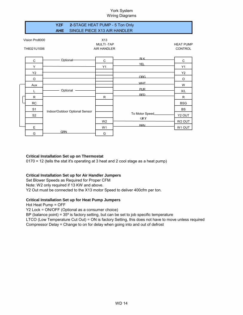
YZF 2-STAGE HEAT PUMP 5 TON ONLYAVG SINGLE PIECE VARIABLE SPEED AIR HANDLERMV TWO PIECE VARIABLE SPEED AIR HANDLER
Vision Pro8000
TH8321U1006VARIABLE SPEED HEAT PUMP
AIR HANDLER CONTROL
C C C
Y Y1 Y1
Y2 Y2
O O O
Aux W
L X/L X/L
R R R
RC BSG
S1 Indoor/Outdoor Optional Sensor HUM BS
S2 Y2/Y Y2 OUT
G G
W2 W2 OUT
E W1 W1 OUT
BLK
YEL
BLU/YEL
ORG
WHT
PUR
RED
BLU
GRY
BRN
GRN

York SystemWiring Diagrams
WD 13
IAQ 9000
NOTES:If 10-wires between the Air Handler and the Heat Pump is not possible W1 and W2 can be combined at the AHwith a jumper eliminating W2 out and staged electric heat. X/L can be eliminated as the fault codes can be retrived from the board.
Please call for more detailed instructions if the number of wires is an issue.
Critical Installation Set up on Thermostat#172, CHANGE TO 2 (tells stat the system in a Heat Pump)#174, CHANGE TO 2 (tells stat number of cooling stages)#176, CHANGE TO 3 (tells stat number of heating stages)#200, CHANGE TO 0 (tells stat back up heat is electric)
Critical Installation Set up for Air Handler JumpersP5 Jumper = Heat P6 Jumper = Heat Pump Set Blower Speeds as Required for Proper CFM. P9 = Heat,P10 = Delay,P8 = Cool,P11 = Adj.
Critical Installation Set up for Heat Pump JumpersHot Heat Pump = ON/OFF (optional) Y2 Lock = ON/OFF (Optional) Switch Point = 35º is Factory DefaultBP (balance point) = 35º is factory setting, but should be set to job specific temperature LTCO (Low Temperature Cut Out) = ON is factory Setting, this does not have to move unless requiredCompressor Delay = Change to on for delay when going into and out of defrost
YZF 2-STAGE HEAT PUMP 5 TON ONLYAVG SINGLE PIECE VARIABLE SPEED AIR HANDLERMV TWO PIECE VARIABLE SPEED AIR HANDLERHONEYWELL 9000 IAQ THERMOSTAT
TO THERMOSTAT
YTH9421C1002VARIABLE SPEED HEAT PUMP
AIR HANDLER CONTROL
1
2
3
C C C
Y Y1 Y1
Y2 Y2
O O O
AUX W
L X/L X/L
R R R
W2 OUT
RC BSG
RH HUM BS
Aux 2 W1 W1 OUT
G G
Y2/Y Y2 OUT
W2
BLK
YEL
BLU/YEL
ORG
WHT
PUR
RED
BLU
GRY
BRN
GRN
York System Wiring Diagrams
WD 14
MULTI -TAP
Optional
Optional
Critical Installation Set up on Thermostat0170 = 12 (tells the stat it's operating at 3 heat and 2 cool stage as a heat pump)
Critical Installation Set up for Air Handler JumpersSet Blower Speeds as Required for Proper CFMNote: W2 only required if 13 KW and above.Y2 Out must be connected to the X13 motor Speed to deliver 400cfm per ton.
Critical Installation Set up for Heat Pump JumpersHot Heat Pump = OFF Y2 Lock = ON/OFF (Optional as a consumer choice) BP (balance point) = 35º is factory setting, but can be set to job specific temperature LTCO (Low Temperature Cut Out) = ON is factory Setting, this does not have to move unless requiredCompressor Delay = Change to on for delay when going into and out of defrost
YZF 2-STAGE HEAT PUMP - 5 Ton OnlyAHE SINGLE PIECE X13 AIR HANDLER
Vision Pro8000 X13
TH8321U1006HEAT PUMP
AIR HANDLER CONTROL
C C C
Y Y1 Y1
Y2 Y2
O O
Aux W
L X/L
Y2 OUT
R R R
RC BSG
W2 OUT
E W1 W1 OUT
S1 Indoor/Outdoor Optional Sensor BS
S2
G G
To Motor Speed
W2
BLK
ORG
WHT
PUR
RED
BRN
GRN
YEL

York SystemWiring Diagrams
WD 15
MULTI -TAP
Optional
Optional
Critical Installation Set up on Thermostat0170 = 12 (tells the stat it's operating at 3 heat and 2 cool stage as a heat pump)
Critical Installation Set up for Air Handler JumpersP5 Jumper = Heat P6 Jumper = Heat Pump Set Blower Speeds as Required for Proper CFM
Critical Installation Set up for Heat Pump JumpersHot Heat Pump = OFF Y2 Lock = ON/OFF (Optional as a consumer choice) BP (balance point) = 35º is factory setting, but can be set to job specific temperature LTCO (Low Temperature Cut Out) = ON is factory Setting, this does not have to move unless requiredCompressor Delay = Change to on for delay when going into and out of defrost
YZF 1-STAGE HEAT PUMP - 5 Ton OnlyMX TWO PIECE X13 AIR HANDLER
Vision Pro8000 X13
TH8321U1006HEAT PUMP
AIR HANDLER CONTROL
C C C
Y Y1 Y1
Y2 Y/Y2 Y2
O O O
Aux W
L X/L X/L
R R R
RC BSG
S1 Indoor/Outdoor Optional Sensor HUM BS
S2 Y2 OUT
G G
W2 W2 OUT
E W1 W1 OUT
BLK
ORG
WHT
PUR
RED
GRY
BRN
GRN
YEL
BLU/YEL

York System Wiring Diagrams
WD 16
Optional
Optional
*
* OPTIONAL BONNET SENSOR
Critical Installation Set up on Thermostat0170 = 12 (Tells the stat iis operating at 3 heat and 2 cool stage as a heat pump)0200 = 1 (Tells stat back up is fossil fuel)0210 = 1 (Tells stat fossil fuel kit is external)
Critical Installation Set up on Furnace JumpersHeat Pump = YSet Blower Speeds as Required for Proper CFM. Heat, Cool, Delay, AdjustSet Staging Jumper for 10,15,or 20 minutes
Critical Installation Set up for Heat Pump JumpersF Fuel (Fossil Fuel) = ON (Factory Default is off, however it MUST be changed to ON) BP (balance point) = 35º is factory setting, but should be set to job specific temperature Compressor Delay = Change to on for delay when going into and out of defrost
YZF 2-STAGE HEAT PUMP - 5 Ton OnlyTM9V 95% 2 Stage Variable Speed Gas FurnaceTM8V 80% 2 Stage Vairable SpeedGas Furnace
Variable SpeedVision Pro8000 HEAT PUMP
TH8321U1006
GAS FURNACE CONTROL
C C C
Y Y1 Y1
Y2 Y/Y2 Y2
O O O
Aux W
L XL X/L INDOOR A-COILR R R
RC BSG
S1 Indoor/Outdoor Optional Sensor Dhum BS
S2 Y2 OUT
G G
W2 W2 OUT
E W1 W1 OUT
BLK
YEL
ORG
WHT
PUR
RED
BRN

York SystemWiring Diagrams
WD 17
* OPTIONAL BONNET SENSOR
Critical Installation Set up on Thermostat0170 = 7 (Tells the stat system is 2 heat stages and 1 cool stages0200 = 1 (Tells stat back up is fossil fuel)0210 = 1 (Tells stat fossil fuel kit is external)
Critical Installation Set up on Furnace JumpersP4 Jumper = Blower Off Delay P7 Jumper = Fan Speed Contionus FanSet motor speeds as required for proper air flow
Critical Installation Set up for Heat Pump JumpersHot Heat Pump = ON/OFF (optional) Y2 Lock = ON/OFF (Optional) Switch Point = 35º is Factory DefaultBP (balance point) = 35º is factory setting, but should be set to job specific temperature LTCO (Low Temperature Cut Out) = ON is factory Setting, this does not have to move unless requiredCompressor Delay = Change to on for delay when going into and out of defrost
YZF 1-STAGE HEAT PUMP 1.5 - 4 TonTM9X Gas Furnace
TM8X Gas Furnace
Vision Pro8000
TH8321U1006TM9X HEAT PUMP
Gas Furnace CONTROL
C C C
Y Y1 Y1
W
L X/L
Y2 Y2
O O
INDOOR A-COILR R R
RC BSG
S1 Indoor/Outdoor Optional Sensor BS
S2
Y2/Y
Y2 OUT
W2 OUT
AUX
E W W1 OUT
G G
BLK
YEL
ORG
WHTPUR - Optional
RED
BRN
GRN

York SystemWiring Diagrams
WD 18
IAQ 9000
Critical Installation Set up on Thermostat#172, CHANGE TO 2 (tells stat the system in a Heat Pump)#174, CHANGE TO 1 (tells stat number of cooling stages)#176, CHANGE TO 2 (tells stat number of heating stages)#200, CHANGE TO 1 (tells stat back up heat is fossil fuel)#210, CHANGE TO 1 (tells stat fossil fuel is controlled external)
Critical Installation Set up for Furnace JumpersP4 Jumper = Blower Off Delay P7 Jumper = Fan Speed Contionus FanSet motor speeds as required for proper air flow
Critical Installation Set up for Heat Pump JumpersHot Heat Pump = ON/OFF (optional) Y2 Lock = ON/OFF (Optional) Switch Point = 35º is Factory DefaultBP (balance point) = 35º is factory setting, but should be set to job specific temperature LTCO (Low Temperature Cut Out) = ON is factory Setting, this does not have to move unless requiredCompressor Delay = Change to on for delay when going into and out of defrost
YZF 1-STAGE HEAT PUMP 1.5 - 4 Ton TM9X Gas Furnace
TM8X Gas FurnaceHONEYWELL 9000 IAQ THERMOSTAT
TO THERMOSTAT
YTH9421C1002TM9X HEAT PUMP
Gas Furnace CONTROL
1
2
3
C C C
Y Y1 Y1
Y2 Y2
O O
AUX W
L X/L INDOOR A-COILR R R
W2 OUT
RC BSG
RH BS
Aux 2 W W1 OUT
G G
Y2 OUT
BLK
YEL
ORG
WHTPUR - Optional
RED
BRN
GRN
Y2/Y

York SystemWiring Diagrams
WD 19
* OPTIONAL BONNET SENSOR
Critical Installation Set up on Thermostat0170 = 12 (Tells the stat system is 3 heat stages and 2 cool stages0200 = 1 (Tells stat back up is fossil fuel)0210 = 1 (Tells stat fossil fuel kit is external)
Critical Installation Set up on Furnace JumpersP4 Jumper = Blower Off Delay P7 Jumper = Fan Speed Contionus FanSet motor speeds as required for proper air flow
Critical Installation Set up for Heat Pump JumpersHot Heat Pump = ON/OFF (optional) Y2 Lock = ON/OFF (Optional) Switch Point = 35º is Factory DefaultBP (balance point) = 35º is factory setting, but should be set to job specific temperature LTCO (Low Temperature Cut Out) = ON is factory Setting, this does not have to move unless requiredCompressor Delay = Change to on for delay when going into and out of defrost
YZF 2-STAGE HEAT PUMP 5 - Ton OnlyTM9X Gas Furnace
TM8X Gas Furnace
Vision Pro8000
TH8321U1006TM9X HEAT PUMP
Gas Furnace CONTROL
C C C
Y Y1 Y1
Y2 Y2/Y Y2
O O
S1 Indoor/Outdoor Optional Sensor
AUX W
L X/L
W2 OUT
INDOOR A-COILR R R
RC BSG
E W W1 OUT
G G
BS
S2 Y2 OUT
BLK
YEL
ORG
WHTPUR - Optional
RED
BRN
GRN
BLU/Y

York SystemWiring Diagram
WD 20
IAQ 9000
Critical Installation Set up on Thermostat#172, CHANGE TO 2 (tells stat the system in a Heat Pump)#174, CHANGE TO 2 (tells stat number of cooling stages)#176, CHANGE TO 3 (tells stat number of heating stages)#200, CHANGE TO 1 (tells stat back up heat is fossil fuel)#210, CHANGE TO 1 (tells stat fossil fuel is controlled external)
Critical Installation Set up for Furnace JumpersP4 Jumper = Blower Off Delay P7 Jumper = Fan Speed Contionus FanSet motor speeds as required for proper air flow
Critical Installation Set up for Heat Pump JumpersHot Heat Pump = ON/OFF (optional) Y2 Lock = ON/OFF (Optional) Switch Point = 35º is Factory DefaultBP (balance point) = 35º is factory setting, but should be set to job specific temperature LTCO (Low Temperature Cut Out) = ON is factory Setting, this does not have to move unless requiredCompressor Delay = Change to on for delay when going into and out of defrost
YZF 2-STAGE HEAT PUMP 5 - Ton OnlyTM9X Gas Furnace
TM8X Gas FurnaceHONEYWELL 9000 IAQ THERMOSTAT
TO THERMOSTAT
YTH9421C1002TM9X HEAT PUMP
Gas Furnace CONTROL
1
2
3
C C C
Y Y1 Y1
Y2 Y2
O O
AUX W
L X/L INDOOR A-COILR R R
W2 OUT
RC BSG
RH BS
Aux 2 W W1 OUT
G G
Y2 OUT
BLK
YEL
ORG
WHTPUR - Optional
RED
BRN
GRN
Y2/Y BLU/Y

York System Wiring Diagrams
WD 21
Optional
Optional
*
* OPTIONAL BONNET SENSOR * OPTIONAL BONNET SENSOR
Critical Installation Set up on Thermostat1 = 5 (Tells the stat 2 heat stages and 1 cool stage)6 = 5- 80% Furnace 3- 90% or Better (Tells stat furnace efficiency for cycle rates)8 = 5- 80% Furnace 3- 90% or Better (Tells stat furnace efficiency for Emergency cycle rates)
Critical Installation Set up on Furnace JumpersSet Blower Speeds as Required for Proper CFM
Critical Installation Set up for Heat Pump JumpersF Fuel (Fossil Fuel) = ON (Factory Default is off, however it MUST be changed to ON) BP (balance point) = 35º is factory setting, but should be set to job specific temperature Compressor Delay = Change to on for delay when going into and out of defrost
YZF 1-STAGE HEAT PUMP - 1.5 - 4 TonTG9S 90% MULTI-TAP GAS FURNACETG8S 80% MULTI-TAP GAS FURNACE
SINGLE SPEED MULTI-TAPFocus Pro 5000 HEAT PUMP
TH5220D1003 GAS FURNACE CONTROL
C C C
Y Y1
Y2
O O
AUX W
L X/L INDOOR A-COILR R R
W2 OUT
RC BSG
BS
E W W1 OUT
G G
Y/Y2
Y2 OUT
BLK
YEL
ORG
WHT
PUR
RED
BRN

York SystemWiring Diagram
WD 22
Optional
Optional
*
* OPTIONAL BONNET SENSOR
Critical Installation Set up on Thermostat0170 = 7 (Tells the stat iis operating at 2 heat and 1 cool stage as a heat pump)0200 = 1 (Tells stat back up is fossil fuel)0210 = 1 (Tells stat fossil fuel kit is external)
Critical Installation Set up on Furnace JumpersSet Blower Speeds as Required for Proper CFM
Critical Installation Set up for Heat Pump JumpersHot Heat Pump = ON/OFF (Factory Default is OFF, however we recommend it be changed to ON) Y2 Lock = ON/OFF (Factory Default is OFF, however we recommend it be changed to ON) Switch Point = 35º is Factory Default, change if neededF Fuel (Fossil Fuel) = ON (Factory Default is off, however it MUST be changed to ON) BP (balance point) = 35º is factory setting, but should be set to job specific temperature
HEAT PUMP
YZF 1-STAGE HEAT PUMP - 1.5 - 4 TonTG9S 95% Single Stage PSC Gas Furnace
O O
Aux W
C C
Y Y1
L X/L
R R R
Hi Comp
G G
RC BSG
S1 DHUM BS
O
INDOOR A-COIL
Indoor/Outdoor Optional Sensor
W2 OUT
E W W1 OUT
S2 Lo Comp Y2 OUT
TG8S 80% Single Stage PSC Gas Furnace
TH8321U1006 GAS FURNACE CONTROL
C
Y/Y2Y2 Y2
Vision Pro8000 Milti Speed
BLK
YEL
ORG
WHT
PUR
RED
BRN
GRN

York SystemWiring Diagrams
WD 23
Optional
Critical Installation Set up on Thermostat0170 = 8 (tells stat 2 heat stages and 2 cooling stages)0180= 1 (tells stat system is using electric furnace)0240= 9 ( tells stat 1st stage heating cycle rate)0250= 9 (tells stat 2nd stage heating cycle rate)
Critical Installation Set up for Air Handler JumpersP5 Jumper = Heat P6 Jumper = Heat Pump Set Blower Speeds as Required for Proper CFM. P9 = Heat,P10 = Delay,P8 = Cool,P11 = Adj.Critical Installation Set up for Air Conditioning JumpersY2 Lock = ON/OFF (Optional)
CZH 2-STAGE AIR CONDITIONERAVG SINGLE PIECE VARIABLE SPEED AHUMV TWO PIECE VARIABLE SPEED AHU
VARIABLE SPEEDVision Pro8000
TH8321U10062 STAGE A/C
AIR HANDLER CONTROL
C C C
Y Y1 Y1
Y2 Y/Y2 Y2
O
W W1
W2 W2
R R R
RC
S1 Indoor/Outdoor Optional Sensor HUM
S2
G G
X/L
BLK
YEL
RED
BLU/YEL

York SystemWiring Diagrams
WD 24
Optional
Critical Installation Set up on Thermostat0172 = 1 (tells stat Conventional System)0174= 2 (tells stat number of cooling stages)0176= 2 ( tells stat # of heating stages)0180= 2 (tells stat equipment controls fan)
Critical Installation Set up for Air Handler JumpersP5 Jumper = Heat Set Blower Speeds as Required for Proper CFM. P9 = Heat,P10 = Delay,P8 = Cool,P11 = Adj.
Critical Installation Set up for Air Conditioning JumpersY2 Lock = ON/OFF (Optional)
CZH 2-STAGE AIR CONDITIONERAVG SINGLE PIECE VARIABLE SPEED AHUMV TWO PIECE VARIABLE SPEED AHU
VARIABLE SPEEDIAQ 9000
YTH9421C10022 STAGE A/C
AIR HANDLER CONTROL
C C C
Y Y1 Y1
W2
Y2 Y/Y2 Y2
O O
R
RC
AUX W1
L
AUX2
X/L
RH HUM
TO THERMOSTAT
1
2
3
G G
R R
BLK
YEL
RED
BLU/YEL

York SystemWiring Diagram
WD 25
Optional
Critical Installation Set up on Thermostat0170 = 10 (tells stat 1 heat stage and 2 cooling stages)0240= 3 (tells stat 1st stage heaing cycle rate)
Critical Installation Set Up on Furnace1. If zoning is applied, set the "Zone Control" jumper to YES which eliminates the RUN 2 cycle of the furnace which normally begins when the call from the thermostat ends. 2. Set Blower Speeds as Required for Proper CFM
CZH 2-STAGE AIR CONDITIONERYP9C 95% MODULATING VARIABLE SPEED GAS FURNACE
Vision Pro8000
MODULATING
TH8321U1006
2 STAGE A/C
GAS FURNACE CONTROL
C C C
Y Y1 Y1
Y2 Y/Y2 Y2
O
W W
W2
R R R
RC Lo Comp
S1 Indoor/Outdoor Optional Sensor HI Comp
S2
G G
Dhum
BLK
YEL
RED
BLU/YEL
GRN

York SystemWiring Diagram
WD 26
Optional
Critical Installation Set up on Thermostat0172 = 1 (tells stat Conventional System)0174= 2 (tells stat number of cooling stages)0176= 1 ( tells stat # of heating stages)0180= 0 (tells stat equipment controls fan)
Critical Installation Set Up on FurnaceSet Blower Speeds as Required for Proper CFM. J9 = Cool, J16 = Adj, J15 = Delay
G G
TO THERMOSTAT
1
2
3
Dhum
W W
S1 Indoor/Outdoor Optional Sensor HI Comp
S2
R R R
RC Lo Comp
W2
Y2 Y/Y2 Y2
O
C C C
Y Y1 Y1
CZH 2-STAGE AIR CONDITIONERYP9C 95% MODULATING VARIABLE SPEED GAS FURNACE
IAQ 9000
MODULATING
YTH9421C1002
2 STAGE A/C
GAS FURNACE CONTROL
BLK
YEL
RED
BLU/YEL
GRN

York SystemWiring Diagrams
WD 27
Optional
Critical Installation Set up on Thermostat0170 = 8 (tells stat 2 heat stage and 2 cooling stages)0240= 3- 90% Furnace 5-80% Furnace (tells stat 1st stage heaing cycle rate)
Critical Installation Set Up on Furnace
Set Blower Speeds as Required for Proper CFM
G G
Dhum
X/L
S1 Indoor/Outdoor Optional SensorS2
R R R
RC
W W1
W2 W2
Y2 Y/Y2 Y2
O
C C C
Y Y1 Y1
CZH 2-STAGE AIR CONDITIONERTM9V 95% 2 Stage Variable Speed Gas FurnaceTM8V 80% 2 Stage Vairable Speed Gas Furnace
Vision Pro8000
2 Stage
TH8321U1006
2 STAGE A/C
GAS FURNACE CONTROL
BLK
YEL
RED
BLU/YEL
GRN

York SystemWiring Diagrams
WD 28
Optional
Critical Installation Set up on Thermostat0172 = 1 (tells stat Conventional System)0174= 2 (tells stat number of cooling stages)0176= 2 ( tells stat # of heating stages)0180= 0 (tells stat equipment controls fan)
Critical Installation Set Up on FurnaceSet Blower Speeds as Required for Proper CFM
G G
TO THERMOSTAT
1
2
3
Dhum
W W1
X/L
S1 Indoor/Outdoor Optional SensorS2
R R R
RC
W2 W2
Y2 Y/Y2 Y2
O
C C C
Y Y1 Y1
CZH 2-STAGE AIR CONDITIONERTM9V 95% 2 Stage Variable Speed Gas FurnaceTM8V 80% 2 Stage Vairable Speed Gas Furnace
IAQ 9000
2 Stage
YTH9421C1002
2 STAGE A/C
GAS FURNACE CONTROL
BLK
YEL
RED
BLU/YEL
GRN

York SystemWiring Diagram
WD 29
Optional
Critical Installation Set up on Thermostat0170 = 10 (tells stat 1 heat stage and 2 cooling stages)0240= 3- 90% Furnace 5-80% Furnace (tells stat 1st stage heaing cycle rate)
Critical Installation Set Up on Furnace
Set Blower Speeds as Required for Proper CFM
G G
S1 Indoor/Outdoor Optional SensorS2
R R R
RC
W W
W2
Y2 Y/Y2 Y2
C C C
Y Y1 Y1
CZH 2-STAGE AIR CONDITIONERTM9X 95% Single Stage X13 Gas FurnaceTM8X 80% Single Stage X13 Gas Furnace
Vision Pro8000
Single Stage
TH8321U1006
2 STAGE A/C
GAS FURNACE CONTROL
BLK
YEL
RED
BLU/YEL
GRN

York SystemWiring Diagram
WD 30
Optional
Critical Installation Set up on ThermostatParameter 5 = 5 for 80% Furnace or 3 for 90% or Better (tells stat cycle rate)
Critical Installation Set Up on FurnaceSet Blower Speeds as Required for Proper CFM
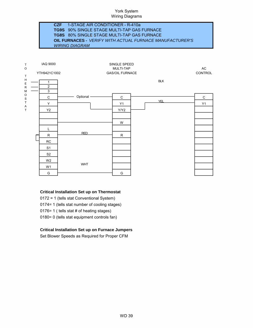
CZH 2-STAGE AIR CONDITIONER - R-410aTG9S 90% SINGLE STAGE MULTI-TAP GAS FURNACETG8S 80% SINGLE STAGE MULTI-TAP GAS FURNACEOIL FURNACES - VERIFY WITH ACTUAL FURNACE MANUFACTURER'S WIRING DIAGRAM
Focus Pro 5000 SINGLE SPEED MULTI-TAP
5110D1006AC
GAS/OIL FURNACE CONTROL
C C C
Y Y1 Y1
Y/Y2
W W
R R
RC
G G
BLK
YEL
WHT
RED

York SystemWiring Diagrams
WD 31
Optional
Critical Installation Set up on Thermostat0170 = 9 (tells stat 2 heat stage and 1 cooling stages)0240= 9 (tells stat 1st stage heaing cycle rate)
Critical Installation Set up for Air Handler JumpersP5 Jumper = Heat Set Blower Speeds as Required for Proper CFM. P9 = Heat,P10 = Delay,P8 = Cool,P11 = Adj.
Critical Installation Set up for Heat Pump JumpersY2 Lock = ON/OFF (Optional)
Vision Pro8000
TH8321U1006
CZF 1-STAGE AIR CONDITIONER - R-410aAVG SINGLE PIECE VARIABLE SPEED AIR HANDLERMV TWO PIECE VARIABLE SPEED AIR HANDLER
VARIABLE SPEEDAIR CONDITIONER
CONTROL
AIR HANDLER
C C C
Y Y1 Y
Y2 Y/Y2
O
W W1
W2 W2
R R
RC
S1 HUM
S2
G G
X/L
BLK
YEL
GRN

York SystemsWiring Diagrams
WD 32
Optional
Critical Installation Set up on Thermostat0172 = 1 (tells stat Conventional System)0174= 1 (tells stat number of cooling stages)0176= 2 ( tells stat # of heating stages)0180= 2 (tells stat equipment controls fan)
Critical Installation Set up for Air Handler JumpersP5 Jumper = Heat Set Blower Speeds as Required for Proper CFM. P9 = Heat,P10 = Delay,P8 = Cool,P11 = Adj.
G G
TO THERMOSTAT
1
2
3
X/L
S1 HUM
S2
R R
RC
W W1
W2 W2
Y2 Y/Y2
O
AIR HANDLER
C C C
Y Y1 Y
CZF 1-STAGE AIR CONDITIONER - R-410aAVG SINGLE PIECE VARIABLE SPEED AIR HANDLERMV TWO PIECE VARIABLE SPEED AIR HANDLER
IAQ 9000
VARIABLE SPEEDYTH9421C1002AIR CONDITIONER
CONTROL
BLK
YEL
GRN

York SystemWiring Diagrams
WD 33
MULTI -TAP
Optional
Critical Installation Set up on Thermostat0170 = 9 (tells the stat it's operating at 2 heat and 1 cool stage Conventional)
Critical Installation Set up for Air Handler JumpersSet Blower Speeds as Required for Proper CFMNote: W2 only required if 13 KW and above.
G G
W2 W2
W W1
S1 Indoor/Outdoor Optional SensorS2
R R
RC
Y2 Y2
C C C
Y Y1 Y1
CZF 1-STAGE AIR CONDITIONERAHE SINGLE PIECE X13 AIR HANDLER
Vision Pro8000 X13
TH8321U1006AIR CONDITIONER
AIR HANDLER CONTROL
BLK
GRN
YEL

York SystemWiring Diagrams
WD 34
MULTI -TAP
Optional
Critical Installation Set up on Thermostat0170 = 9 (tells the stat it's operating at 2 heat and 1 cool stage Conventional)
Critical Installation Set up for Air Handler JumpersP5 Jumper = Heat Set Blower Speeds as Required for Proper CFM
G G
W2 W2
W1 W1
S1 Indoor/Outdoor Optional Sensor HUM
S2
R R
RC
X/L
Y2 Y/Y2 Y2
O
C C C
Y Y1 Y1
CZF 1-STAGE AIR CONDITIONEERMX TWO PIECE X13 AIR HANDLER
Vision Pro8000 X13
TH8321U1006AIR CONDITIONER
AIR HANDLER CONTROL
BLK
GRN
YEL

York SystemWiring Diagram
WD 35
Optional
Critical Installation Set up on Thermostat0170 = 9 (Tells the stat iis operating at 2 heat and 1 cool Conventional)0240= 3- 90% Furnace 5-80% Furnace (tells stat 1st stage heaing cycle rate)
Critical Installation Set up on Furnace Jumpers
Set Blower Speeds as Required for Proper CFM. Heat, Cool, Delay, Adjust
G G
W2 W2
W1 W
RC
S1 Indoor/Outdoor Optional SensorS2
L X/L
R R
O
Y Y1 Y1
Y2 Y/Y2 Y2
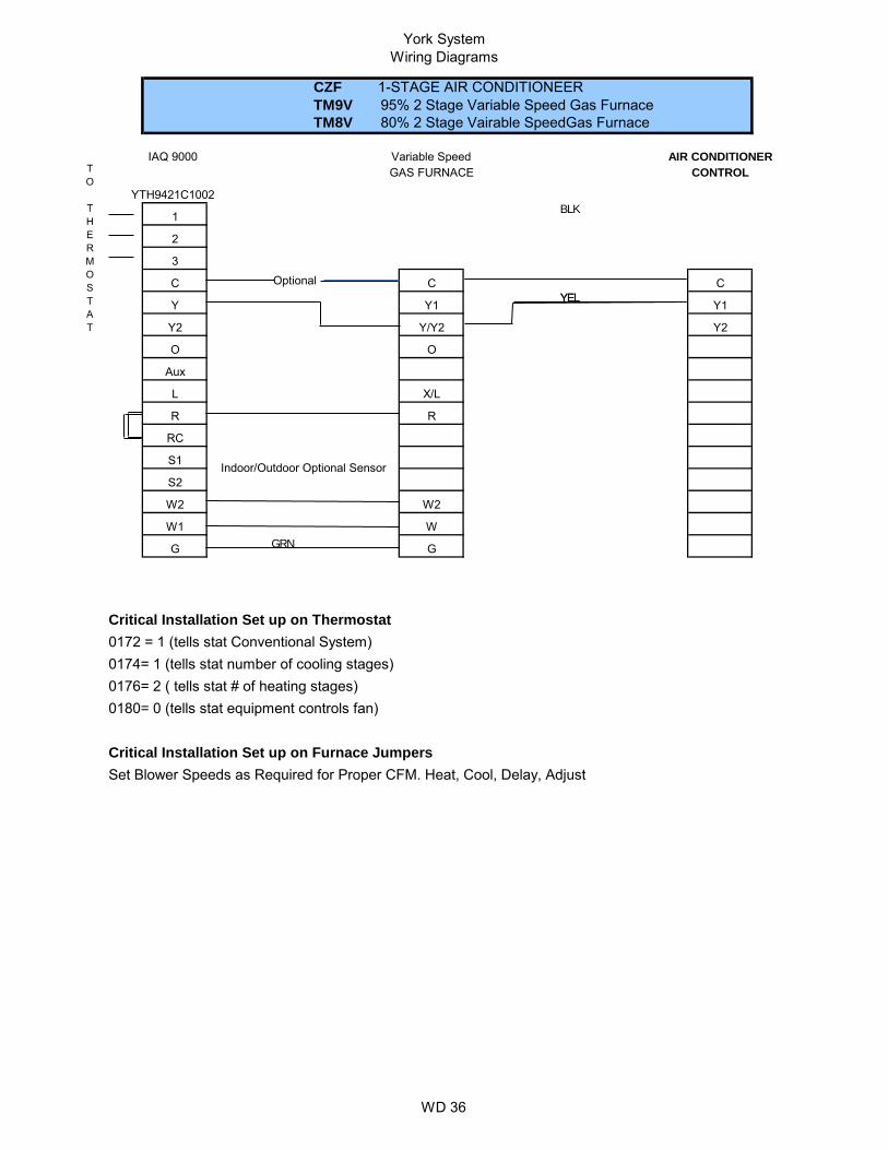
TH8321U1006
GAS FURNACE CONTROL
C C C
CZF 1-STAGE AIR CONDITIONEERTM9V 95% 2 Stage Variable Speed Gas FurnaceTM8V 80% 2 Stage Vairable SpeedGas Furnace
Variable SpeedVision Pro8000 AIR CONDITIONER
BLK
YELYEL
GRN
York SystemWiring Diagrams
WD 36
Optional
Critical Installation Set up on Thermostat0172 = 1 (tells stat Conventional System)0174= 1 (tells stat number of cooling stages)0176= 2 ( tells stat # of heating stages)0180= 0 (tells stat equipment controls fan)
Critical Installation Set up on Furnace JumpersSet Blower Speeds as Required for Proper CFM. Heat, Cool, Delay, Adjust
G G
TO THERMOSTAT
1
2
3
W2 W2
W1 W
RC
S1 Indoor/Outdoor Optional SensorS2
L X/L
R R
O O
Aux
Y Y1 Y1
Y2 Y/Y2 Y2
YTH9421C1002
GAS FURNACE CONTROL
C C C
CZF 1-STAGE AIR CONDITIONEERTM9V 95% 2 Stage Variable Speed Gas FurnaceTM8V 80% 2 Stage Vairable SpeedGas Furnace
Variable SpeedIAQ 9000 AIR CONDITIONER
BLK
YELYEL
GRN

York SystemWiring Diagrams
WD 37
Optional
Critical Installation Set up on Thermostat0170 = 1 (tells stat 1 heat stage and 1 cooling stages)0240= 3- 90% Furnace 5-80% Furnace (tells stat 1st stage heaing cycle rate)
Critical Installation Set Up on Furnace
Set Blower Speeds as Required for Proper CFM
G G
S1 Indoor/Outdoor Optional SensorS2
R R R
RC
W W
W2
Y2 Y/Y2 Y2
C C C
Y Y1 Y1
CZF 1-STAGE AIR CONDITIONERTM9X 95% Single Stage X13 Gas FurnaceTM8X 80% Single Stage X13 Gas Furnace
Vision Pro8000
Single Stage
TH8321U1006
2 STAGE A/C
GAS FURNACE CONTROL
BLK
YEL
RED
GRN

York SystemWiring Diagrams
WD 38
Optional
Critical Installation Set up on Thermostat0170 = 9 (Tells the stat iis operating at 2 heat and 1 cool Conventional)0240= 3- 90% Furnace 5-80% Furnace (tells stat 1st stage heaing cycle rate)
Critical Installation Set Up on FurnaceSet Blower Speeds as Required for Proper CFM
CZF 1-STAGE AIR CONDITIONER - R-410aTG9S 90% SINGLE STAGE MULTI-TAP GAS FURNACETG8S 80% SINGLE STAGE MULTI-TAP GAS FURNACEOIL FURNACES - VERIFY WITH ACTUAL FURNACE MANUFACTURER'S WIRING DIAGRAM
Vision Pro8000 SINGLE SPEED MULTI-TAP
TH8321U1006AC
GAS/OIL FURNACE CONTROL
C C C
Y Y1 Y1
Y2 Y/Y2
W
L
R R
RC
S1
S2
W2
W1
G G
BLK
YEL
WHT
RED
York SystemWiring Diagrams
WD 39
Optional
Critical Installation Set up on Thermostat0172 = 1 (tells stat Conventional System)0174= 1 (tells stat number of cooling stages)0176= 1 ( tells stat # of heating stages)0180= 0 (tells stat equipment controls fan)
Critical Installation Set up on Furnace JumpersSet Blower Speeds as Required for Proper CFM
TO THERMOSTAT
W1
RC
R
C
Y Y1
G G
S2
W2
S1
W
L
R
Y2 Y/Y2
Y1
CZF 1-STAGE AIR CONDITIONER - R-410aTG9S 90% SINGLE STAGE MULTI-TAP GAS FURNACETG8S 80% SINGLE STAGE MULTI-TAP GAS FURNACEOIL FURNACES - VERIFY WITH ACTUAL FURNACE MANUFACTURER'S WIRING DIAGRAM
IAQ 9000
12
SINGLE SPEED MULTI-TAP
YTH9421C1002AC
GAS/OIL FURNACE CONTROL
C C
3
BLK
YEL
WHT
RED

York SysteWiring Diagrams
WD 40
MULTI -TAP
Optional
Optional
Critical Installation Set up on Thermostat0170 = 7 (tells the stat it's operating at 2 heat and 1 cool stage as a heat pump)
Critical Installation Set up for Air Handler JumpersSet Blower Speeds as Required for Proper CFMNote: W2 only required if 13 KW and above.
Critical Installation Set up for Heat Pump JumpersDefrost Curve = Position 2
G G
W2
E W1 W1/66
S1 Indoor/Outdoor Optional SensorS2
R R R
RC
Aux W
L X/L
Y2
O O
C C C
Y Y1 Y
YHJF 1-STAGE HEAT PUMP - 1.5 - 4 TonAHE SINGLE PIECE X13 AIR HANDLER
Vision Pro8000 X13
TH8321U1006HEAT PUMP
AIR HANDLER CONTROL
BLK
ORG
WHT
PUR
RED
BRN
GRN
YEL

York SystemWiring Diagrams
WD 41
Optional
Optional
Blue
Critical Installation Set up on Thermostat0170 = 7 (Tells the stat iis operating at 2 heat and 1 cool stage as a heat pump)0180 = 1 ( Fan is controlled by thermostst)
Note: Outdoor sensor cable must be separate from the thermostat cable.
Critical Installation Set up on Air HandlerSet Blower Speeds as Required for Proper CFM Heat Enable = Yes if Electric Heater is installedHunidistat = Set to yes if Humidistat is presentHeat Pump = Yes
Critical Installation Set up for Heat Pump JumpersDefrost Curve Position 2
YHJF 1-STAGE HEAT PUMP - R-410a 1.5 - 4 Tons MX Air Handler with X13 Motor
Vision Pro8000 HEAT PUMP
TH8321U1006 MX CONTROL
C C C
Y Y1 Y
Y2 Y/Y2
O O O
Aux W
L XL X/L
R R R
RC
S1 OutdoorSensor OptionalS2 W1 W1/66
G G
W2
E Hum
BLK
YEL
ORG
WHT
PUR
RED
GRN
York SystemWiring Diagrams
WD 42
Optional
Optional
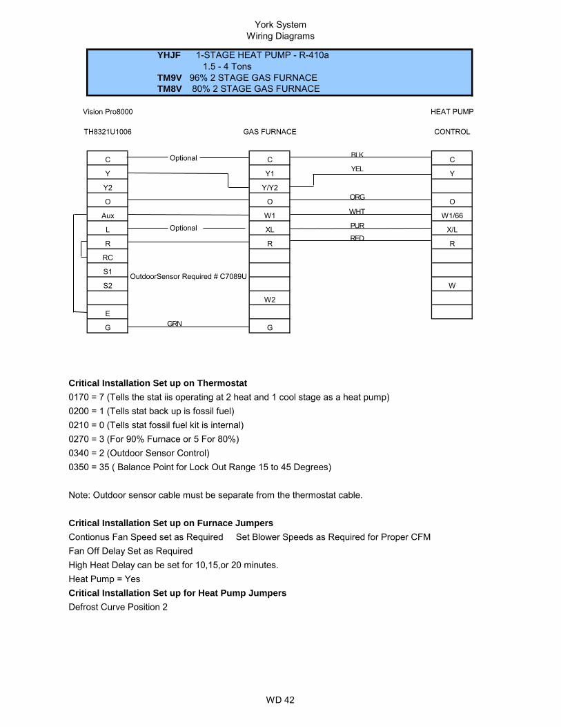
Critical Installation Set up on Thermostat0170 = 7 (Tells the stat iis operating at 2 heat and 1 cool stage as a heat pump)0200 = 1 (Tells stat back up is fossil fuel)0210 = 0 (Tells stat fossil fuel kit is internal)0270 = 3 (For 90% Furnace or 5 For 80%)0340 = 2 (Outdoor Sensor Control) 0350 = 35 ( Balance Point for Lock Out Range 15 to 45 Degrees)
Note: Outdoor sensor cable must be separate from the thermostat cable.
Critical Installation Set up on Furnace JumpersContionus Fan Speed set as Required Set Blower Speeds as Required for Proper CFM Fan Off Delay Set as RequiredHigh Heat Delay can be set for 10,15,or 20 minutes.Heat Pump = YesCritical Installation Set up for Heat Pump JumpersDefrost Curve Position 2
YHJF 1-STAGE HEAT PUMP - R-410a 1.5 - 4 Tons TM9V 96% 2 STAGE GAS FURNACETM8V 80% 2 STAGE GAS FURNACE
Vision Pro8000 HEAT PUMP
TH8321U1006 GAS FURNACE CONTROL
C C C
Y Y1 Y
Y2 Y/Y2
O O O
Aux W1 W1/66
L XL X/L
R R R
RC
S1 OutdoorSensor Required # C7089US2 W
G G
W2
E
BLK
YEL
ORG
WHT
PUR
RED
GRN

York SystemWiring Diagrams
WD 43
Optional
Optional
Critical Installation Set up on Thermostat0170 = 7 (Tells the stat iis operating at 2 heat and 1 cool stage as a heat pump)0200 = 1 (Tells stat back up is fossil fuel)0210 = 0 (Tells stat fossil fuel kit is internal)0270 = 3 (For 90% Furnace or 5 For 80%)0340 = 2 (Outdoor Sensor Control) 0350 = 35 ( Balance Point for Lock Out Range 15 to 45 Degrees)
Note: Outdoor sensor cable must be separate from the thermostat cable.
Critical Installation Set up on Furnace JumpersContionus Fan Spped set as Required Set Blower Speeds as Required for Proper CFM Fan Off Delay Set as Required
Critical Installation Set up for Heat Pump JumpersDefrost Curve Position 2
YHJF 1-STAGE HEAT PUMP - R-410a 1.5 - 4 Tons TM9X 95% SINGLE STAGE GAS FURNACETM8X 80% SINGLE STAGE GAS FURNACE
Vision Pro8000 HEAT PUMP
TH8321U1006 GAS FURNACE CONTROL
C C C
Y Y1 Y
Y2 Y/Y2
O O
Aux W W1/66
L X/L
R R R
RC
S1 OutdoorSensor Required # C7089US2
G G
E W
BLK
YEL
ORG
WHT
PUR
RED
GRN

York SystemWiring Diagrams
WD 44
Optional
Optional
*
* OPTIONAL BONNET SENSOR * OPTIONAL BONNET SENSOR
Critical Installation Set up on Thermostat0170 = 7 (tells the stat iis operating at 2 heat and 1 cool stage as a heat pump)0200 = 1 (Tells stat back up is fossil fuel)0210 = 1 (Tells stat fossil fuel kit is external)
Critical Installation Set up on Furnace JumpersContionus Fan Spped set as Required Set Blower Speeds as Required for Proper CFM Fan Off Delay Set as RequiredHigh Heat Delay can be set for 10,15,20 minutes.Heat Pump = Yes
Critical Installation Set up for Heat Pump JumpersHot Heat Pump = ON/OFF (Factory Default is OFF, but it must be turned ON for this application) Y2 Lock = ON/OFF (Factory Default is OFF, however we recommend it be changed to ON) Switch Point = 35º is Factory Default, change if neededF Fuel (Fossil Fuel) = ON (Factory Default is off, however it MUST be changed to ON) BP (balance point) = 35º is factory setting, but should be set to job specific temperature
YHJF 2-STAGE HEAT PUMP - R-410a 5 Tons OnlyTM9V 96% 2 STAGE GAS FURNACETM8V 80% 2 STAGE GAS FURNACE
Vision Pro 8000 HEAT PUMP
TH8321U1006
GAS FURNACE CONTROL
C C C
Y Y1 Y1
Y2 Y2
O O O
Aux W
L X/L INDOOR A-COILR R R
W2 OUT
RC BSG
S1 BS
E W1 W1 OUT
G G
S2 Y/Y2 Y2 OUT
W2
BLK
YEL
ORG
WHT
PUR
RED
BRN
Blu
Blu/Yel

York SystemWiring Diagrams
WD 45
Optional
Optional
*
* OPTIONAL BONNET SENSOR * OPTIONAL BONNET SENSOR
Critical Installation Set up on Thermostat0170 = 7 (tells the stat iis operating at 2 heat and 1 cool stage as a heat pump)0200 = 1 (Tells stat back up is fossil fuel)0210 = 1 (Tells stat fossil fuel kit is external)
Critical Installation Set up on Furnace JumpersContionus Fan Spped set as Required Set Blower Speeds as Required for Proper CFM Fan Off Delay Set as Required
Critical Installation Set up for Heat Pump JumpersHot Heat Pump = ON/OFF (Factory Default is OFF, But it must be turned on for this application) Y2 Lock = ON/OFF (Factory Default is OFF) Switch Point = 35º is Factory Default, change if neededF Fuel (Fossil Fuel) = ON (Factory Default is off, however it MUST be changed to ON) BP (balance point) = 35º is factory setting, but should be set to job specific temperature
YHJF 2-STAGE HEAT PUMP - R-410a 5 Tons OnlyTM9X 95% SINGLE STAGE GAS FURNACETM8X 80% SINGLE STAGE GAS FURNACE
Vision Pro 8000 HEAT PUMP
TH8321U1006
GAS FURNACE CONTROL
C C C
Y Y1 Y1
Y2 Y2
O O
Aux W
L X/L INDOOR A-COILR R R
RC BSG
S1 Indoor/Outdoor optional sensor BS
S2 Y/Y2 Y2 OUT
G G
W2 OUT
E W W1 OUT
BLK
YEL
ORG
WHT
PUR
RED
BRN
Blu
Blu/Yel

York SystemWiring Diagrams
WD 46
MULTI -TAP
Optional
Optional
Critical Installation Set up on Thermostat0170 = 7 (tells the stat it's operating at 2 heat and 1 cool stage as a heat pump)
Critical Installation Set up for Air Handler JumpersSet Blower Speeds as Required for Proper CFMNote: W2 only required if 13 KW and above.
Critical Installation Set up for Heat Pump JumpersDefrost Time 30,60,90 Minutes
G G
W2
E W1 W1/66
S1 Indoor/Outdoor Optional SensorS2
R R R
RC
Aux W
L X/L
Y2
O O
C C C
Y Y1 Y
YHJD 1-STAGE HEAT PUMP - AHE SINGLE PIECE X13 AIR HANDLER
Vision Pro8000 X13
TH8321U1006HEAT PUMP
AIR HANDLER CONTROL
BLK
ORG
WHT
PUR
RED
BRN
GRN
YEL

York SystemWiring Diagrams
WD 47
Optional
Optional
Blue
Critical Installation Set up on Thermostat0170 = 7 (Tells the stat iis operating at 2 heat and 1 cool stage as a heat pump)0180 = 1 ( Fan is controlled by thermostst)Note: Outdoor sensor cable must be separate from the thermostat cable.
Critical Installation Set up on Air HandlerSet Blower Speeds as Required for Proper CFM Heat Enable = Yes if Electric Heater is installedHunidistat = Set to yes if Humidistat is presentHeat Pump = Yes
Critical Installation Set up for Heat Pump JumpersDefrost Time 30,60,90 Minutes
G G
W2
E Hum
RC
S1 OutdoorSensor OptionalS2 W1 W1/66
L XL X/L
R R R
O O O
Aux W
Y Y1 Y
Y2 Y/Y2
TH8321U1006 AHX CONTROL
C C C
YHJD 1-STAGE HEAT PUMP - R-410a 1.5 - 4 Tons MX Air Handler with X13 Motor
Vision Pro8000 HEAT PUMP
BLK
YEL
ORG
WHT
PUR
RED
GRN

York SystemWiring Diagrams
WD 48
Optional
Optional
Critical Installation Set up on Thermostat0170 = 7 (Tells the stat iis operating at 2 heat and 1 cool stage as a heat pump)0200 = 1 (Tells stat back up is fossil fuel)0210 = 0 (Tells stat fossil fuel kit is internal)0270 = 3 (For 90% Furnace or 5 For 80%)0340 = 2 (Outdoor Sensor Control) 0350 = 35 ( Balance Point for Lock Out Range 15 to 45 Degrees)
Note: Outdoor sensor cable must be separate from the thermostat cable.
Critical Installation Set up on Furnace JumpersContionus Fan Spped set as Required Set Blower Speeds as Required for Proper CFM Fan Off Delay Set as Required
Critical Installation Set up for Heat Pump JumpersDefrost Time 30,60,90 Minutes
YHJD 1-STAGE HEAT PUMP - R-410a 1.5 - 5 Tons TM9X 95% SINGLE STAGE GAS FURNACETM8X 80% SINGLE STAGE GAS FURNACE
Vision Pro8000 HEAT PUMP
TH8321U1006 GAS FURNACE CONTROL
C C C
Y Y1 Y
Y2 Y/Y2
O O
Aux W W1/66
L X/L
R R R
RC
S1 OutdoorSensor Required # C7089US2
G G
E W
BLK
YEL
ORG
WHT
PUR
RED
GRN

York SystemWiring Diagrams
WD49
Optional
Optional
Critical Installation Set up on Thermostat0170 = 7 (Tells the stat iis operating at 2 heat and 1 cool stage as a heat pump)0190 = 0 ( Reversing Valve in Normal Heat Mode)0200 = 1 (Tells stat back up is fossil fuel)0210 = 0 (Tells stat fossil fuel kit is internal)0270 = 3 (For 90% Furnace or 5 For 80%)0340 = 2 (Outdoor Sensor Control) 0350 = 35 ( Balance Point for Lock Out Range 15 to 45 Degrees)
Note: Outdoor sensor cable must be separate from the thermostat cable.
Critical Installation Set up on Furnace JumpersContionus Fan Spped set as Required Set Blower Speeds as Required for Proper CFM Fan Off Delay Set as Required
Critical Installation Set up for Heat Pump JumpersDefrost Time 30,60,90 Minutes
G G
E W
RC
S1 OutdoorSensor Required # C7089US2
L X/L
R R R
O O
Aux W W1/66
Y Y Y
Y2
TH8321U1006 GAS FURNACE CONTROL
C C C
YHJR 1-STAGE HEAT PUMP - R-410a 1.5 - 5 Tons TG9S 95% SINGLE STAGE GAS FURNACETG8S 80% SINGLE STAGE GAS FURNACE
Vision Pro8000 HEAT PUMP
BLK
YEL
ORG
WHT
PUR
RED
GRN

York SystemWiring Diagrams
WD50
Optional
Critical Installation Set up on Thermostat0170 = 1 (tells stat 1 heat stage and 1 cooling stages)0240= 3- 90% Furnace 5-80% Furnace (tells stat 1st stage heaing cycle rate)
Critical Installation Set Up on Furnace
Set Blower Speeds as Required for Proper CFM
G G
S1 Indoor/Outdoor Optional SensorS2
R R
RC
W W
W2
Y2 Y/Y2
C C C
Y Y1 Y1
YCJF 1-STAGE AIR CONDITIONERTM9X 95% Single Stage X13 Gas FurnaceTM8X 80% Single Stage X13 Gas Furnace
Vision Pro8000
Single Stage
TH8321U1006
2 STAGE A/C
GAS FURNACE CONTROL
BLK
YEL
GRN

York SystemWiring Diagrams
WD 51
Optional
Critical Installation Set up on Thermostat0170 = 1 (tells stat 1 heat stage and 1 cooling stages)0240= 3- 90% Furnace 5-80% Furnace (tells stat 1st stage heaing cycle rate)
Critical Installation Set Up on Furnace
Set Blower Speeds as Required for Proper CFM
G G
S1 Indoor/Outdoor Optional SensorS2
R R
RC
W W
W2
Y2 Y/Y2
C C C
Y Y1 Y1
YCJD 1-STAGE AIR CONDITIONERTM9X 95% Single Stage X13 Gas FurnaceTM8X 80% Single Stage X13 Gas Furnace
Vision Pro8000
Single Stage
TH8321U1006
2 STAGE A/C
GAS FURNACE CONTROL
BLK
YEL
GRN