yor loal partner for a motion tehnolo -...
TRANSCRIPT
Your Global Partner for Cam Motion Technology
EU Head Office
CDS Cam Driven Systems div. Bettinelli F.lli S.p.AVia Leonardo da Vinci 5626010 Bagnolo Cr.sco (CR)Phone +39 0373 237 311Fax +39 0373 237 [email protected]
U.S.A. Corporate Office
CDS Corp.Cam Driven Systems27 Wilson Drive, Unit CSparta NJ 07871 Phone +1 973 300 0090Fax +1 973 300 [email protected]
Germany Corporate Office
CDS GmbHCam Driven SystemsUlrichstrasse 986641 Rain am LechPhone +49(0)9090 7057110Fax +49(0)9090 [email protected]
India Corporate Office
Bettinelli Automation Components Pvt. Ltd.Office # 3, 1st FloorDestination CenterMagarpatta City HadapsarPune 411-013 Phone +91 20 6723 6484Fax +91 20 6723 [email protected]
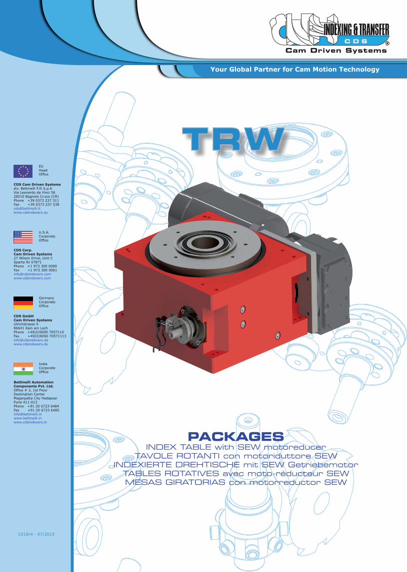
PACKAGESINDEX TABLE with SEW motoreducer
TAVOLE ROTANTI con motoriduttore SEWINDEXIERTE DREHTISCHE mit SEW Getriebemotor
TABLES ROTATIVES avec moto-réducteur SEW MESAS GIRATORIAS con motorreductor SEW
C018/4 - 07/2015
TRW

3
TRWC018/4 - 07/2015
Summary Sommario Inhaltsver-zeichnis Index Sumario
Technical Data Descrizione tecnica Technische Angaben Donnees techniques Datos técnicos 4-5
Repeatability Ripetibilità Wiederholbarkeit Répétabilité Repetibilidad 4-5
Loads on output flange Carichi sul divisore Lasten auf dem Teilgerät
Charges sur le diviseur Tiempos de ciclo con motorreductor
6-7
Sizing software Programma di dimensionamento
Dimensionierungs Programm
Programme de dimensionnement
Programa de dimensionamiento
6-7
Inertia 50 Hz Inerzia 50 Hz Trägheit 50 Hz Inertie 50 Hz Inercia 50 Hz 8-11
Cycle times with motoreducer
Tempi di ciclo motoriduttore
Zykluszeiten mit Untersetzermotor
Temps de cycle avec motoreducteur
Tiempos de ciclo con motorreductor
12
Motor power Potenza motore Leistung Motor Puissance moteur Potencia motor 13
Designation Designazione Bezeichnung Désignation Designación 13
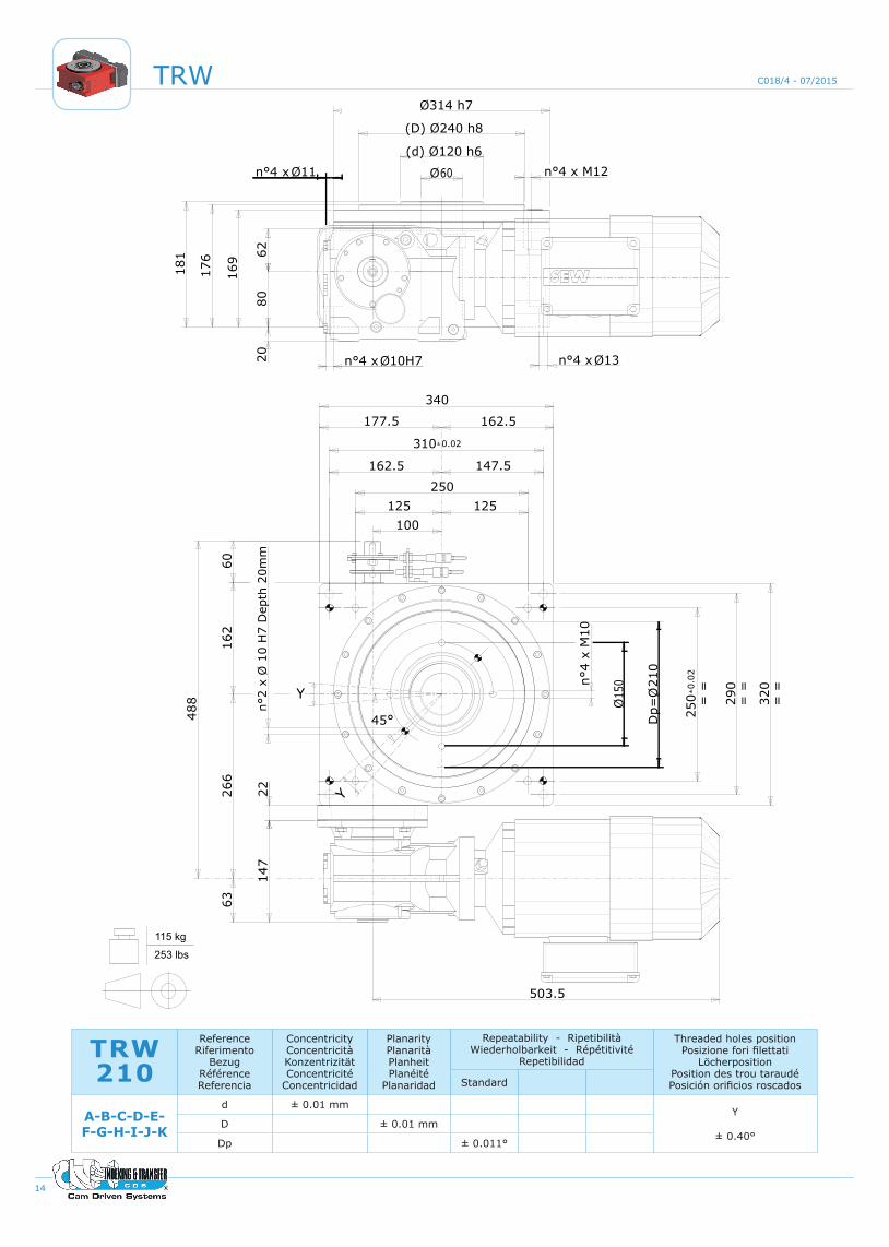
TRW 210 Dimensions TRW 210 Dimensioni TRW 210 Außenmaße TRW 210 Dimensions TRW 210 Dimensiones 14
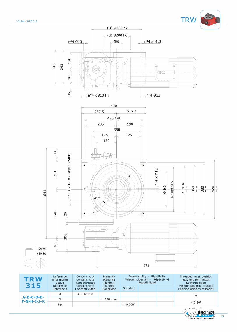
TRW 315 Dimensions TRW 315 Dimensioni TRW 315 Außenmaße TRW 315 Dimensions TRW 315 Dimensiones 15
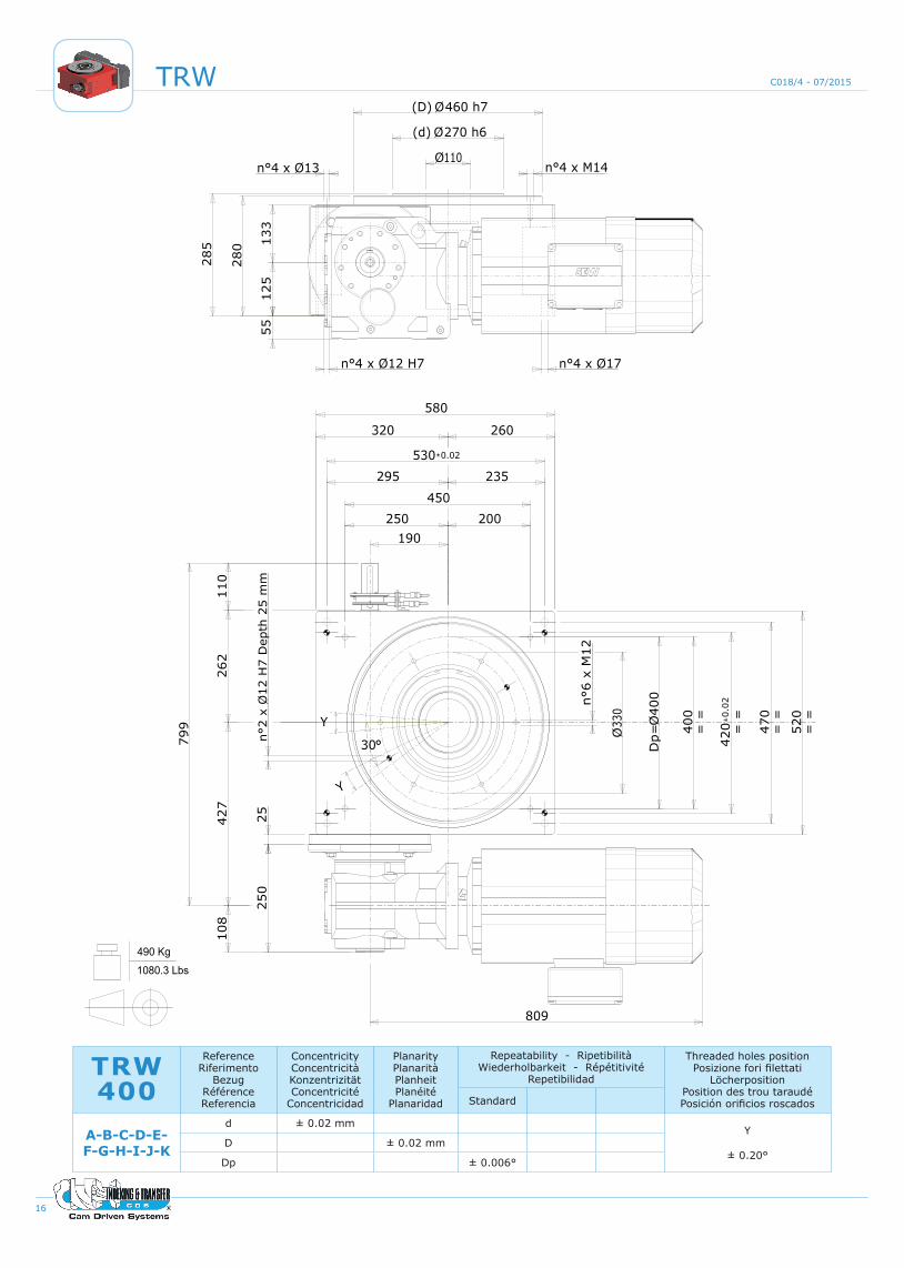
TRW 400 Dimensions TRW 400 Dimensioni TRW 400 Außenmaße TRW 400 Dimensions TRW 400 Dimensiones 16
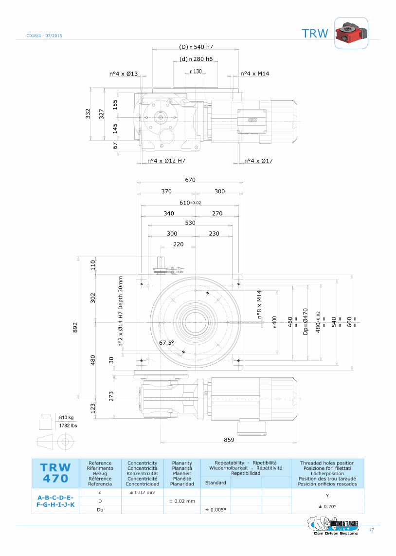
TRW 470 Dimensions TRW 470 Dimensioni TRW 470 Außenmaße TRW 470 Dimensions TRW 470 Dimensiones 17
Proximity sensors & Phase cams operation
Sensore proxy e camma di fase
Proximity-sensor und phasennocken
Capteur proxy et came de phase
Sensor proxy y leva de fase
18-21
4
TRW C018/4 - 07/2015
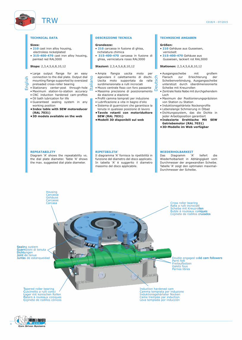
TECHNICAL DATA
Sizes: • 210 cast iron alloy housing, electroless nickelplated• 315-400-470 cast iron alloy housing,
painted red RAL3000
Stops: 2,3,4,5,6,8,10,12
• Large output flange for an easy connection to the dial plate. Output dial mounting flange supported by oversized preloaded cross-roller bearing
• Stationary center-post through-hole• Maximum station-to-station accuracy • CNC induction hardened cam-profiles • Oil bath lubrication for life• Guaranteed sealing system in any
working position•Index table with SEW motoreducer
(RAL 7031) •3D models available on the web
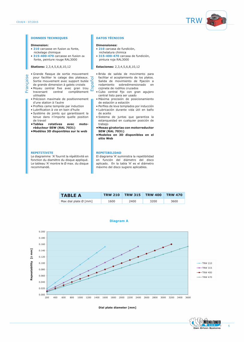
REPEATABILITYDiagram ‘A’ shows the repeatability vs. the dial plate diameter. Table ‘A’ shows the max. suggested dial plate diameter.
Engl
ish
DESCRIZIONE TECNICA
Grandezze: • 210 carcassa in fusione di ghisa, nichelatura chimica• 315-400-470 carcassa in fusione di
ghisa, verniciatura rosso RAL3000
Stazioni: 2,3,4,5,6,8,10,12 • Ampia flangia uscita moto per
agevolare il calettamento di dischi. Uscita moto supportata da ralla surdimensionata a rulli incrociati
• Mozzo centrale fisso con foro passante• Massima precisione di posizionamento
da stazione a stazione • Profili camma temprati per induzione • Lubrificazione a vita in bagno d’olio • Sistema di guarnizioni che garantisce la
tenuta in qualsiasi posizione di lavoro •Tavole rotanti con motoriduttore
SEW (RAL 7031)•Modelli 3D disponibili sul web
RIPETIBILITA’Il diagramma ‘A’ fornisce la ripetibilità in funzione del diametro del disco applicato. In tabella ‘A’ è suggerito il diametro massimo del disco applicabile.
Ital
iano
TECHNISCHE ANGABEN
Größen: • 210 Gehäuse aus Gusseisen, vernickelt• 315-400-470 Gehäuse aus Gusseisen, lackiert rot RAL3000
Stationen: 2,3,4,5,6,8,10,12
• Ausgangsscheibe mit großem Flansch zur Erleichterung der Scheibenverbindung. Ausgangsscheibe unterstüzt durch überdimensionierte Scheibe mit Kreuzrollen
• Zentrale feste Nabe mit durchgehendem Loch
• Maximum der Positionierungspräzision von Station zu Station
• Induktionsgehärtete Nockenprofile• Lebenslange Schmierung in Ölbad• Dichtungssystem, das die Dichte in
jeder Arbeitsposition garantiert •Indexierte Drehtische Mit SEW
Getriebemotor (RAL 7031)•3D-Modelle im Web verfügbar
WIEDERHOLBARKEITDas Diagramm ‘A’ liefert die Wiederholbarkeit in Abhängigkeit vom Durchmesser der angewandten Scheibe. Tabelle ‘A’ zeigt den optimalen maximal- Durchmesser der Scheibe.
Deu
tsch
HousingCarcassaGehäuseCarcasseCarcasa Cross roller bearing
Ralla a rulli incrociatiScheibe mit KreuzrollenButée à rouleaux coniquesCojinete de rodillos cruzados
Double engaged solid cam followersPerni folliFreilaufbolzenGalets fousPernos libres
Induction hardened camCamma temprata per induzioneInduktionsgehärteter NockenCame trempée par inductionLeva templada por inducción
Tapered roller bearingCuscinetto a rulli coniciLager mit konischen RollenPaliers à rouleaux coniquesCojinete de rodillos cónicos
Sealing systemGuarnizioni di tenutaDichtungenJoint de tenueJuntas de estanqueidad
5
TRWC018/4 - 07/2015
DONNEES TECHNIQUES
Dimension: • 210 carcasse en fusion de fonte, nickelage chimique• 315-400-470 carcasse en fusion de fonte, peinture rouge RAL3000
Stations: 2,3,4,5,6,8,10,12
• Grande flasque de sortie mouvement pour faciliter le calage des plateaux.Sortie mouvement avec support butée de grande dimension à galets croisés
• Moyeu central fixe avec gran trou traversant central complètement utilisable
• Précision maximale de positionnement d’une station à l’autre
• Profiles came temprée par induction• Lubrification à vie en bain d’huile• Système de joints qui garantissent la
tenue dans n’importe quelle position de travail•Tables rotatives avec moto-
réducteur SEW (RAL 7031)•Modèles 3D disponibles sur le web
REPETITIVITELe diagramme ‘A’ fournit la répétitivité en fonction du diamètre du disque appliqué. Le tableau ‘A’ montre le Ø max. du disque recommandé.
Fran
çais
e
DATOS TÉCNICOS
Dimensiones: • 210 carcasa de fundición, nichelatura chimica• 315-400-470 carcasa de fundición, pintura roja RAL3000
Estaciones: 2,3,4,5,6,8,10,12
• Brida de salida de movimento para facilitar el acoplamiento de los platos.Salida de movimiento de fijación a rodamiento sobredimensionado en cojinete de rodillos cruzados
• Cubo central fijo con gran agujero central listo para ser usado
• Máxima precisión de posicionamiento de estación a estación
• Perfiles de leva templados por inducción • Lubricación durante vida útil en baño
de aceite • Sistema de juntas que garantiza la
estanqueidad en cualquier posición de trabajo •Mesas giratorias con motorreductor
SEW (RAL 7031)•Modelos en 3D disponibles en el
sitio Web
REPETIBILIDADEl diagrama ‘A’ suministra la repetibilidad en función del diámetro del disco aplicado. En la tabla ‘A’ es el diámetro máximo del disco sugiere aplicables.
Espa
ñol
TABLE A TRW 210 TRW 315 TRW 400 TRW 470
Max dial plate Ø [mm] 1600 2400 3200 3600
0.000
0.020
0.040
0.060
0.080
0.100
0.120
0.140
0.160
0.180
0.200
200 400 600 800 1000 1200 1400 1600 1800 2000 2200 2400 2600 2800 3000 3200 3400 3600
Rep
eata
bili
ty
[±m
m]
Dial plate diameter [mm]
Diagram A
TRW 210
TRW 315
TRW 400
TRW 470
6
TRW C018/4 - 07/2015
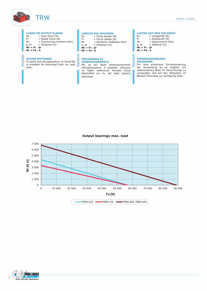
LOADS ON OUTPUT FLANGEFa = Axial force (N)Fr = Radial Force (N)Mr = Overturning moment (Nm)b, dr = Distance (m)Mr = Fr . drMr = Fa . b
SIZING SOFTWARETo easily size the application, an Excel file is available for download from our web sites.
Engl
ish
CARICHI SUL DIVISOREFa = Forza assiale (N)Fr = Forza radiale (N)Mr = Momento ribaltante (Nm)b, dr = Distanza (m)Mr = Fr . drMr = Fa . b
PROGRAMMA DI DIMENSIONAMENTOPer un più facile dimensionamento dell’applicazione, è possibile utilizzare un foglio elettronico formato Excel disponibile sui ns. siti nella sezione download.
Ital
iano
LASTEN AUF DEM TEILGERÄTFa = Längskraft (N)Fr = Radialkraft (N)Mr = Kippmoment (Nm)b, dr = Abstand (m)Mr = Fr . drMr = Fa . b
DIMENSIONIERUNGSPROGRAMMFür eine einfachere Dimensionierung der Anwendung ist es möglich, ein elektronisches Blatt im Excel-Format zu verwenden, das auf den Webseiten im Bereich Download zur Verfügung steht.
Deu
tsch
0
1 000
2 000
3 000
4 000
5 000
6 000
7 000
0 10 000 20 000 30 000 40 000 50 000 60 000 70 000 80 000 90 000
Mr [
N m
]
Fa [N]
Output bearings max. load
TRW 210 TRW 315 TRW 400 -TRW 470
7
TRWC018/4 - 07/2015
CHARGES SUR LE DIVISEURFa = Force axiale (N)Fr = Force radiale (N)Mr = Moment renversé (Nm)b, dr = Distance (m)Mr = Fr . drMr = Fa . b
PROGRAMME DE DIMENSIONNEMENT Pour un dimensionnement plus facile de l’application, il est possible d’utiliser un fichier électronique en format Excel disponible sur nos sites à la section ‘Téléchargement’.
Fran
çais
e
CARGAS EN EL DIVISORFa = Fuerza axial (N)Fr = Fuerza radial (N)Mr = Momento de vuelco (Nm)b, dr = Distancia (m)Mr = Fr . drMr = Fa . b
PROGRAMA DE DIMENSIONAMIENTOPara que el dimensionamiento de la aplicación sea más fácil, es posible utilizar una hoja electrónica en formato Excel, disponible en nuestros sitios Web en la sección de descarga.
Espa
ñol
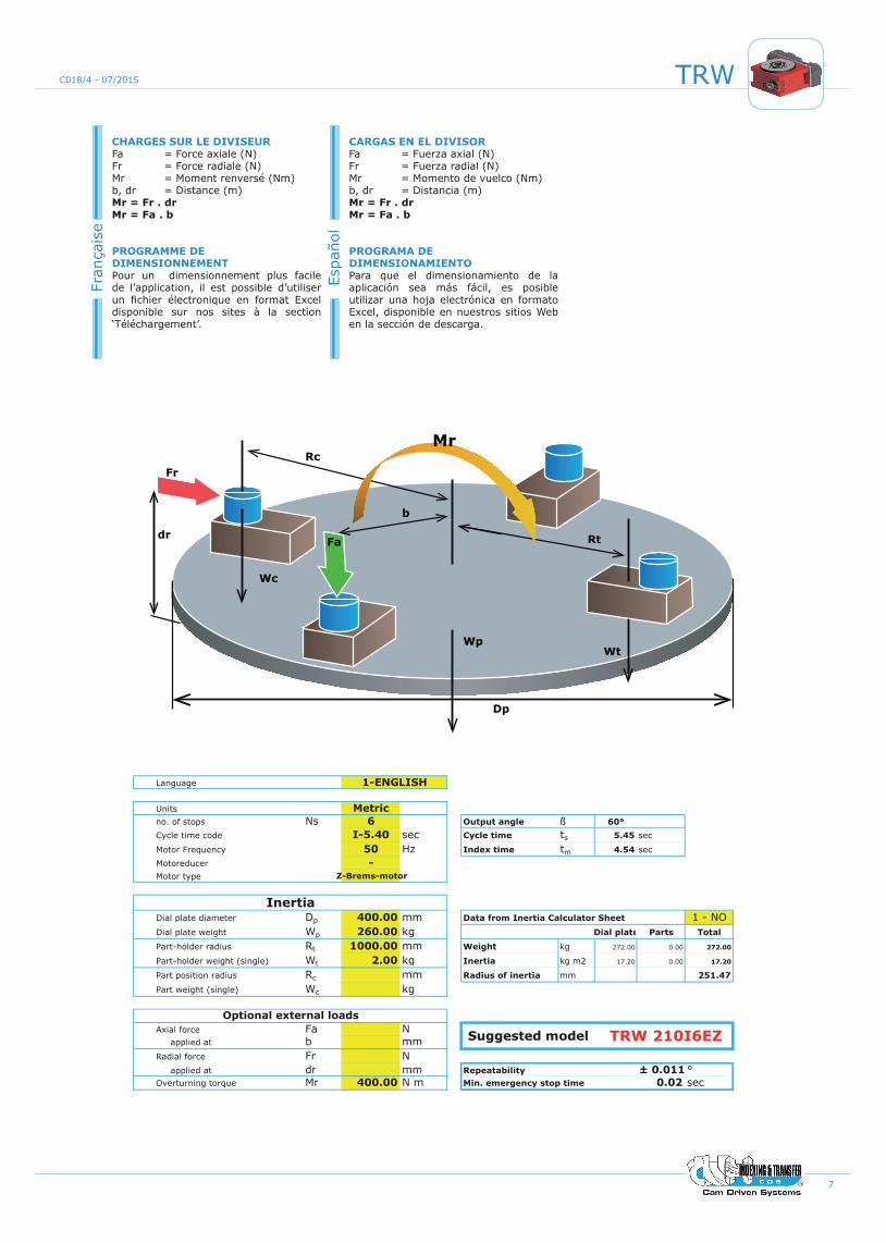
Language 1
Units Metricno. of stops Ns 6 Output angle 60°Cycle time code I-5.40 sec # Cycle time ts 5.45 sec
Motor Frequency 50 Hz Index time tm 4.54 secMotoreducer - 1Motor type Z-Brems-motor
Dial plate diameter Dp 400.00 mm # 1 - NODial plate weight Wp 260.00 kg # Dial plate Parts Total
Part-holder radius Rt 1000.00 mm 0 Weight kg 272.00 0.00 272.00
Part-holder weight (single) Wt 2.00 kg # Inertia kg m2 17.20 0.00 17.20
Part position radius Rc mm 2 Radius of inertia mm 251.47
Part weight (single) Wc kg 0
Axial force Fa N 0 applied at b mm 0Radial force Fr N 0 applied at dr mm 0 ± 0.011 °Overturning torque Mr 400.00 N m 1 0.02 sec
Rev. 3.1 - 08/2014 - 1110
Suggested model
1-ENGLISH
Optional external loads
InertiaData from Inertia Calculator Sheet
TRW 210I6EZ
Repeatability Min. emergency stop time
ß
Dp
WpWt
Rt
b
MrRc
Wc
Fa
Fr
dr
8
TRW C018/4 - 07/2015
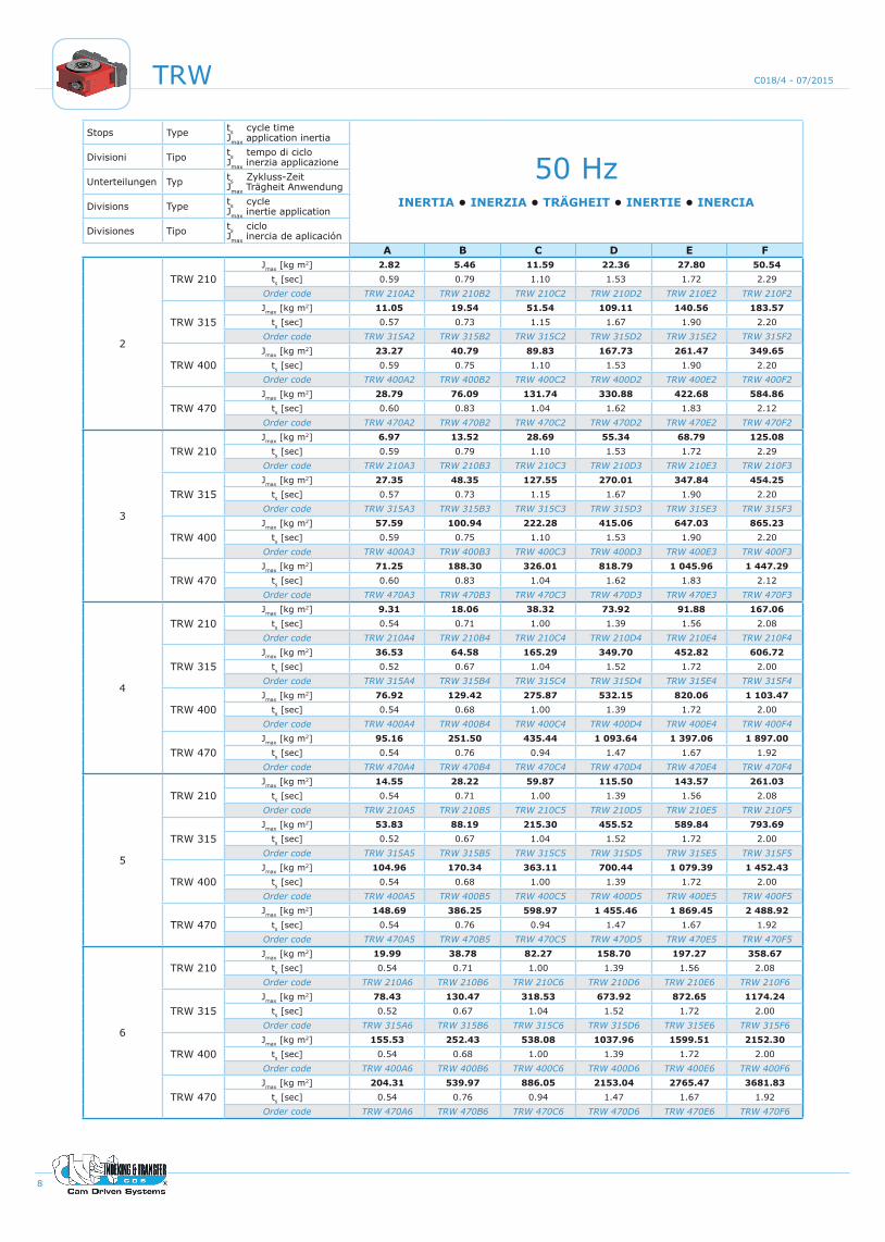
Stops Type ts cycle time Jmax application inertia
50 HzINERTIA • INERZIA • TRÄGHEIT • INERTIE • INERCIA
Divisioni Tipo ts tempo di ciclo Jmax inerzia applicazione
Unterteilungen Typ ts Zykluss-Zeit Jmax Trägheit Anwendung
Divisions Type ts cycle Jmax inertie application
Divisiones Tipo ts ciclo Jmax inercia de aplicación
A B C D E F
2
TRW 210Jmax [kg m2] 2.82 5.46 11.59 22.36 27.80 50.54
ts [sec] 0.59 0.79 1.10 1.53 1.72 2.29Order code TRW 210A2 TRW 210B2 TRW 210C2 TRW 210D2 TRW 210E2 TRW 210F2
TRW 315Jmax [kg m2] 11.05 19.54 51.54 109.11 140.56 183.57
ts [sec] 0.57 0.73 1.15 1.67 1.90 2.20Order code TRW 315A2 TRW 315B2 TRW 315C2 TRW 315D2 TRW 315E2 TRW 315F2
TRW 400Jmax [kg m2] 23.27 40.79 89.83 167.73 261.47 349.65
ts [sec] 0.59 0.75 1.10 1.53 1.90 2.20Order code TRW 400A2 TRW 400B2 TRW 400C2 TRW 400D2 TRW 400E2 TRW 400F2
TRW 470Jmax [kg m2] 28.79 76.09 131.74 330.88 422.68 584.86
ts [sec] 0.60 0.83 1.04 1.62 1.83 2.12Order code TRW 470A2 TRW 470B2 TRW 470C2 TRW 470D2 TRW 470E2 TRW 470F2
3
TRW 210Jmax [kg m2] 6.97 13.52 28.69 55.34 68.79 125.08
ts [sec] 0.59 0.79 1.10 1.53 1.72 2.29Order code TRW 210A3 TRW 210B3 TRW 210C3 TRW 210D3 TRW 210E3 TRW 210F3
TRW 315Jmax [kg m2] 27.35 48.35 127.55 270.01 347.84 454.25
ts [sec] 0.57 0.73 1.15 1.67 1.90 2.20Order code TRW 315A3 TRW 315B3 TRW 315C3 TRW 315D3 TRW 315E3 TRW 315F3
TRW 400Jmax [kg m2] 57.59 100.94 222.28 415.06 647.03 865.23
ts [sec] 0.59 0.75 1.10 1.53 1.90 2.20Order code TRW 400A3 TRW 400B3 TRW 400C3 TRW 400D3 TRW 400E3 TRW 400F3
TRW 470Jmax [kg m2] 71.25 188.30 326.01 818.79 1 045.96 1 447.29
ts [sec] 0.60 0.83 1.04 1.62 1.83 2.12Order code TRW 470A3 TRW 470B3 TRW 470C3 TRW 470D3 TRW 470E3 TRW 470F3
4
TRW 210Jmax [kg m2] 9.31 18.06 38.32 73.92 91.88 167.06
ts [sec] 0.54 0.71 1.00 1.39 1.56 2.08Order code TRW 210A4 TRW 210B4 TRW 210C4 TRW 210D4 TRW 210E4 TRW 210F4
TRW 315Jmax [kg m2] 36.53 64.58 165.29 349.70 452.82 606.72
ts [sec] 0.52 0.67 1.04 1.52 1.72 2.00Order code TRW 315A4 TRW 315B4 TRW 315C4 TRW 315D4 TRW 315E4 TRW 315F4
TRW 400Jmax [kg m2] 76.92 129.42 275.87 532.15 820.06 1 103.47
ts [sec] 0.54 0.68 1.00 1.39 1.72 2.00Order code TRW 400A4 TRW 400B4 TRW 400C4 TRW 400D4 TRW 400E4 TRW 400F4
TRW 470Jmax [kg m2] 95.16 251.50 435.44 1 093.64 1 397.06 1 897.00
ts [sec] 0.54 0.76 0.94 1.47 1.67 1.92Order code TRW 470A4 TRW 470B4 TRW 470C4 TRW 470D4 TRW 470E4 TRW 470F4
5
TRW 210Jmax [kg m2] 14.55 28.22 59.87 115.50 143.57 261.03
ts [sec] 0.54 0.71 1.00 1.39 1.56 2.08Order code TRW 210A5 TRW 210B5 TRW 210C5 TRW 210D5 TRW 210E5 TRW 210F5
TRW 315Jmax [kg m2] 53.83 88.19 215.30 455.52 589.84 793.69
ts [sec] 0.52 0.67 1.04 1.52 1.72 2.00Order code TRW 315A5 TRW 315B5 TRW 315C5 TRW 315D5 TRW 315E5 TRW 315F5
TRW 400Jmax [kg m2] 104.96 170.34 363.11 700.44 1 079.39 1 452.43
ts [sec] 0.54 0.68 1.00 1.39 1.72 2.00Order code TRW 400A5 TRW 400B5 TRW 400C5 TRW 400D5 TRW 400E5 TRW 400F5
TRW 470Jmax [kg m2] 148.69 386.25 598.97 1 455.46 1 869.45 2 488.92
ts [sec] 0.54 0.76 0.94 1.47 1.67 1.92Order code TRW 470A5 TRW 470B5 TRW 470C5 TRW 470D5 TRW 470E5 TRW 470F5
6
TRW 210Jmax [kg m2] 19.99 38.78 82.27 158.70 197.27 358.67
ts [sec] 0.54 0.71 1.00 1.39 1.56 2.08Order code TRW 210A6 TRW 210B6 TRW 210C6 TRW 210D6 TRW 210E6 TRW 210F6
TRW 315Jmax [kg m2] 78.43 130.47 318.53 673.92 872.65 1174.24
ts [sec] 0.52 0.67 1.04 1.52 1.72 2.00Order code TRW 315A6 TRW 315B6 TRW 315C6 TRW 315D6 TRW 315E6 TRW 315F6
TRW 400Jmax [kg m2] 155.53 252.43 538.08 1037.96 1599.51 2152.30
ts [sec] 0.54 0.68 1.00 1.39 1.72 2.00Order code TRW 400A6 TRW 400B6 TRW 400C6 TRW 400D6 TRW 400E6 TRW 400F6
TRW 470Jmax [kg m2] 204.31 539.97 886.05 2153.04 2765.47 3681.83
ts [sec] 0.54 0.76 0.94 1.47 1.67 1.92Order code TRW 470A6 TRW 470B6 TRW 470C6 TRW 470D6 TRW 470E6 TRW 470F6
9
TRWC018/4 - 07/2015
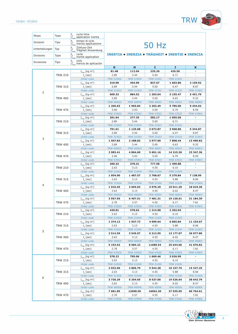
Stops Type ts cycle time Jmax application inertia
50 HzINERTIA • INERZIA • TRÄGHEIT • INERTIE • INERCIA
Divisioni Tipo ts tempo di ciclo Jmax inerzia applicazione
Unterteilungen Typ ts Zykluss-Zeit Jmax Trägheit Anwendung
Divisions Type ts cycle Jmax inertie application
Divisiones Tipo ts ciclo Jmax inercia de aplicación
G H I J K
2
TRW 210Jmax [kg m2] 81.48 112.04 235.26 426.56 -
ts [sec] 2.89 3.44 5.00 6.71 -Order code TRW 210G2 TRW 210H2 TRW 210I2 TRW 210J2 -
TRW 315Jmax [kg m2] 319.90 454.90 837.67 1 603.86 2 159.92
ts [sec] 2.89 3.44 5.00 6.47 8.87Order code TRW 315G2 TRW 315H2 TRW 315I2 TRW 315J2 TRW 315K2
TRW 400Jmax [kg m2] 609.33 884.52 1 203.04 3 155.47 5 451.79
ts [sec] 2.89 3.44 5.00 6.63 9.32Order code TRW 400G2 TRW 400H2 TRW 400I2 TRW 400J2 TRW 400K2
TRW 470Jmax [kg m2] 1 205.63 1 965.84 2 263.49 5 785.00 9 434.92
ts [sec] 3.06 3.93 5.00 6.79 8.59Order code TRW 470G2 TRW 470H2 TRW 470I2 TRW 470J2 TRW 470K2
3
TRW 210Jmax [kg m2] 201.64 277.25 582.17 1 055.56 -
ts [sec] 2.89 3.44 5.00 6.71 -Order code TRW 210G3 TRW 210H3 TRW 210I3 TRW 210J3 -
TRW 315Jmax [kg m2] 791.61 1 125.68 2 072.87 3 968.86 5 344.87
ts [sec] 2.89 3.44 5.00 6.47 8.87Order code TRW 315G3 TRW 315H3 TRW 315I3 TRW 315J3 TRW 315K3
TRW 400Jmax [kg m2] 1 507.83 2 188.82 2 977.00 7 808.44 13 490.82
ts [sec] 2.89 3.44 5.00 6.63 9.32Order code TRW 400G3 TRW 400H3 TRW 400I3 TRW 400J3 TRW 400K3
TRW 470Jmax [kg m2] 2 983.41 4 864.60 5 601.16 14 315.36 23 347.36
ts [sec] 3.06 3.93 5.00 6.79 8.59Order code TRW 470G3 TRW 470H3 TRW 470I3 TRW 470J3 TRW 470K3
4
TRW 210Jmax [kg m2] 269.32 370.31 777.58 1 409.88 -
ts [sec] 2.63 3.13 4.55 6.10 -Order code TRW 210G4 TRW 210H4 TRW 210I4 TRW 210J4 -
TRW 315Jmax [kg m2] 1 054.90 1 487.57 2 768.67 5 270.84 7 138.99
ts [sec] 2.63 3.13 4.55 5.88 8.06Order code TRW 315G4 TRW 315H4 TRW 315I4 TRW 315J4 TRW 315K4
TRW 400Jmax [kg m2] 1 910.45 2 694.03 3 976.29 10 011.20 18 019.30
ts [sec] 2.63 3.13 4.55 6.02 8.47Order code TRW 400G4 TRW 400H4 TRW 400I4 TRW 400J4 TRW 400K4
TRW 470Jmax [kg m2] 3 957.95 6 497.51 7 481.31 19 120.61 31 184.39
ts [sec] 2.78 3.57 4.55 6.17 7.81Order code TRW 470G4 TRW 470H4 TRW 470I4 TRW 470J4 TRW 470K4
5
TRW 210Jmax [kg m2] 420.81 578.62 1 214.98 2 202.94 -
ts [sec] 2.63 3.13 4.55 6.10 -Order code TRW 210G5 TRW 210H5 TRW 210I5 TRW 210J5 -
TRW 315Jmax [kg m2] 1 374.12 1 937.72 4 099.64 6 865.84 11 154.67
ts [sec] 2.63 3.13 4.55 5.88 8.06Order code TRW 315G5 TRW 315H5 TRW 315I5 TRW 315J5 TRW 315K5
TRW 400Jmax [kg m2] 2 514.59 3 545.97 6 212.95 13 177.07 26 077.80
ts [sec] 2.63 3.13 4.55 6.02 8.47Order code TRW 400G5 TRW 400H5 TRW 400I5 TRW 400J5 TRW 400K5
TRW 470Jmax [kg m2] 5 192.92 8 584.22 11689.54 25 644.06 41 076.82
ts [sec] 2.78 3.57 4.55 6.17 7.81Order code TRW 470G5 TRW 470H5 TRW 470I5 TRW 470J5 TRW 470K5
6
TRW 210Jmax [kg m2] 578.22 795.06 1 669.46 3 026.99 -
ts [sec] 2.63 3.13 4.55 6.10 -Order code TRW 210G6 TRW 210H6 TRW 210I6 TRW 210J6 -
TRW 315Jmax [kg m2] 2 032.96 2 866.79 5 944.28 10 157.75 15 327.25
ts [sec] 2.63 3.13 4.55 5.88 8.06Order code TRW 315G6 TRW 315H6 TRW 315I6 TRW 315J6 TRW 315K6
TRW 400Jmax [kg m2] 3 726.29 5 254.65 8 537.00 19 526.64 38 643.79
ts [sec] 2.63 3.13 4.55 6.02 8.47Order code TRW 400G6 TRW 400H6 TRW 400I6 TRW 400J6 TRW 400K6
TRW 470Jmax [kg m2] 7 681.85 12698.56 16062.20 37 935.05 60 764.61
ts [sec] 2.78 3.57 4.55 6.17 7.81Order code TRW 470G6 TRW 470H6 TRW 470I6 TRW 470J6 TRW 470K6
10
TRW C018/4 - 07/2015
Stops Type ts cycle time Jmax application inertia
50 HzINERTIA • INERZIA • TRÄGHEIT • INERTIE • INERCIA
Divisioni Tipo ts tempo di ciclo Jmax inerzia applicazione
Unterteilungen Typ ts Zykluss-Zeit Jmax Trägheit Anwendung
Divisions Type ts cycle Jmax inertie application
Divisiones Tipo ts ciclo Jmax inercia de aplicación
A B C D E F
8
TRW 210Jmax [kg m2] 35.54 66.41 130.16 251.09 317.78 564.95
ts [sec] 0.54 0.71 1.00 1.39 1.56 2.08Order code TRW 210A8 TRW 210B8 TRW 210C8 TRW 210D8 TRW 210E8 TRW 210F8
TRW 315Jmax [kg m2] 109.09 178.74 436.37 923.22 1195.47 1608.63
ts [sec] 0.52 0.67 1.04 1.52 1.72 2.00Order code TRW 315A8 TRW 315B8 TRW 315C8 TRW 315D8 TRW 315E8 TRW 315F8
TRW 400Jmax [kg m2] 214.12 347.52 740.77 1428.95 2202.04 2963.06
ts [sec] 0.54 0.68 1.00 1.39 1.72 2.00Order code TRW 400A8 TRW 400B8 TRW 400C8 TRW 400D8 TRW 400E8 TRW 400F8
TRW 470Jmax [kg m2] 363.22 784.83 1217.06 2958.36 3798.57 5.057.27
ts [sec] 0.54 0.76 0.94 1.47 1.67 1.92Order code TRW 470A8 TRW 470B8 TRW 470C8 TRW 470D8 TRW 470E8 TRW 470F8
10
TRW 210Jmax [kg m2] 47.64 84.09 164.82 317.93 402.38 715.34
ts [sec] 0.54 0.71 1.00 1.39 1.56 2.08Order code TRW 210A10 TRW 210B10 TRW 210C10 TRW 210D10 TRW 210E10 TRW 210F10
TRW 315Jmax [kg m2] 138.19 226.40 552.75 1 169.45 1 514.30 2 037.64
ts [sec] 0.52 0.67 1.04 1.52 1.72 2.00Order code TRW 315A10 TRW 315B10 TRW 315C10 TRW 315D10 TRW 315E10 TRW 315F10
TRW 400Jmax [kg m2] 271.86 441.24 940.54 1 814.31 2 795.90 3 762.16
ts [sec] 0.54 0.68 1.00 1.39 1.72 2.00Order code TRW 400A10 TRW 400B10 TRW 400C10 TRW 400D10 TRW 400E10 TRW 400F10
TRW 470Jmax [kg m2] 512.20 995.24 1 543.35 3 750.23 4 816.97 6 413.12
ts [sec] 0.54 0.76 0.94 1.47 1.67 1.92Order code TRW 470A10 TRW 470B10 TRW 470C10 TRW 470D10 TRW 470E10 TRW 470F10
12
TRW 210Jmax [kg m2] 40.13 70.83 138.84 267.82 338.96 602.59
ts [sec] 0.54 0.71 1.00 1.39 1.56 2.08Order code TRW 210A12 TRW 210B12 TRW 210C12 TRW 210D12 TRW 210E12 TRW 210F12
TRW 315Jmax [kg m2] 166.51 272.81 666.04 1 409.15 1 824.69 2 455.30
ts [sec] 0.52 0.67 1.04 1.52 1.72 2.00Order code TRW 315A12 TRW 315B12 TRW 315C12 TRW 315D12 TRW 315E12 TRW 315F12
TRW 400Jmax [kg m2] 329.10 534.13 1 138.55 2 196.27 3 384.51 4 554.19
ts [sec] 0.54 0.68 1.00 1.39 1.72 2.00Order code TRW 400A12 TRW 400B12 TRW 400C12 TRW 400D12 TRW 400E12 TRW 400F12
TRW 470Jmax [kg m2] 619.61 1 203.94 1 866.98 4 536.63 5 827.05 7 757.90
ts [sec] 0.54 0.76 0.94 1.47 1.67 1.92Order code TRW 470A12 TRW 470B12 TRW 470C12 TRW 470D12 TRW 470E12 TRW 470F12
• The cycle time ‘ts’ is for continuous motion. For cycle-on-demand applications the value ‘ts’ is affected by the delay of the electronic equipments connected
• Il tempo di ciclo ‘ts’ è valido per un funzionamento in continuo. Per posizionamento a consenso il tempo ‘ts’ è modificato dai ritardi delle apparecchiature elettroniche collegate
• Die Zykluszeit ‘ts’ steht für kontinuierlichen Lauf bzw. Bewegung. Für eine Start-Stopp-Bewegung wird der Wert ‘ts’ durch die Verwendung der elektronischen Software verzögert
• Le temp de cycle ‘ts’ est valable pour un fonctionnement en continu. Pour un fonctionnement en temporisé, le temp ‘ts’ est modifié par les retards des appareils électroniques connectés
• El tiempo de ciclo ‘ts’ es válido para un posicionamiento con movimiento en continuo. Para los posicionamientos con movimientos con consenso el tiempo ‘ts’ es modificado por los retrasos de los equipos eléctricos conectados.
!
11
TRWC018/4 - 07/2015
Stops Type ts cycle time Jmax application inertia
50 HzINERTIA • INERZIA • TRÄGHEIT • INERTIE • INERCIA
Divisioni Tipo ts tempo di ciclo Jmax inerzia applicazione
Unterteilungen Typ ts Zykluss-Zeit Jmax Trägheit Anwendung
Divisions Type ts cycle Jmax inertie application
Divisiones Tipo ts ciclo Jmax inercia de aplicación
G H I J K
8
TRW 210Jmax [kg m2] 901.41 1 271.13 2 689.33 4 839.52 -
ts [sec] 2.63 3.13 4.55 6.10 -Order code TRW 210G8 TRW 210H8 TRW 210I8 TRW 210J8 -
TRW 315Jmax [kg m2] 2 785.02 3 927.31 8 309.02 13 915.45 26 154.81
ts [sec] 2.63 3.13 4.55 5.88 8.06Order code TRW 315G8 TRW 315H8 TRW 315I8 TRW 315J8 TRW 315K8
TRW 400Jmax [kg m2] 5 129.96 7 234.04 15 176.89 26 882.20 53 200.66
ts [sec] 2.63 3.13 4.55 6.02 8.47Order code TRW 400G8 TRW 400H8 TRW 400I8 TRW 400J8 TRW 400K8
TRW 470Jmax [kg m2] 10 551.58 17 442.42 28 253.83 52 106.59 83 464.68
ts [sec] 2.78 3.57 4.55 6.17 7.81Order code TRW 470G8 TRW 470H8 TRW 470I8 TRW 470J8 TRW 470K8
10
TRW 210Jmax [kg m2] 1 141.38 1 609.52 3 405.27 6 127.87 -
ts [sec] 2.63 3.13 4.55 6.10 -Order code TRW 210G10 TRW 210H10 TRW 210I10 TRW 210J10 -
TRW 315Jmax [kg m2] 3 527.78 4 974.72 10 525.02 17 626.68 33 130.26
ts [sec] 2.63 3.13 4.55 5.88 8.06Order code TRW 315G10 TRW 315H10 TRW 315I10 TRW 315J10 TRW 315K10
TRW 400Jmax [kg m2] 6 513.43 9 184.96 19 432.63 34 131.93 67 548.08
ts [sec] 2.63 3.13 4.55 6.02 8.47Order code TRW 400G10 TRW 400H10 TRW 400I10 TRW 400J10 TRW 400K10
TRW 470Jmax [kg m2] 13 380.46 22 118.72 35 828.67 66 076.35 105 841.54
ts [sec] 2.78 3.57 4.55 6.17 7.81Order code TRW 470G10 TRW 470H10 TRW 470I10 TRW 470J10 TRW 470K10
12
TRW 210Jmax [kg m2] 961.47 1 355.82 2 868.51 5 161.96 -
ts [sec] 2.63 3.13 4.55 6.10 -Order code TRW 210G12 TRW 210H12 TRW 210I12 TRW 210J12 -
TRW 315Jmax [kg m2] 4 250.87 5 994.39 12 682.35 21 239.65 39 921.03
ts [sec] 2.63 3.13 4.55 5.88 8.06Order code TRW 315G12 TRW 315H12 TRW 315I12 TRW 315J12 TRW 315K12
TRW 400Jmax [kg m2] 7 884.68 11 118.63 23 523.72 41 317.60 81 768.73
ts [sec] 2.63 3.13 4.55 6.02 8.47Order code TRW 400G12 TRW 400H12 TRW 400I12 TRW 400J12 TRW 400K12
TRW 470Jmax [kg m2] 16 186.24 26 756.85 43 341.67 79 932.06 128 035.70
ts [sec] 2.78 3.57 4.55 6.17 7.81Order code TRW 470G12 TRW 470H12 TRW 470I12 TRW 470J12 TRW 470K12
• For optimum performance of the unit in the emergency-stop condition, we recommend dynamic braking using an inverter, with minimum deceleration time calculated using our sizing software based on the application data provided.
• Per un ottimale utilizzo dell’unità durante le fermate di emergenza, si suggerisce l’utilizzo di un inverter con tempi di frenata come da sizing form.
• Um eine optimale Nutzung der Einheit während des Nothalts zu gewährleisten, wird die Nutzung eines Inverters mit Haltezeiten - wie in den Dimensionierungspro grammdaten angegeben empfohlen.
• Pour une utilisation optimal de l’appareil lors des arrêts d’urgence il est conseillé d’utiliser un variateur de fréquence ,programmé suivant les donnees indiquees dans la feuille de calcul.
• Para un uso óptimo de la unidad durante las paradas de emergencia, se sugiere el uso de un inverter con el tiempo de paro como indicado en los datos técnicos del programa de cálculo.
!
12
TRW C018/4 - 07/2015
CYCLE TIMES WITH MOTOREDUCER • TEMPI DI CICLO MOTORIDUTTOREZYKLUSZEITEN MIT UNTERSETZERMOTOR
TEMPS DE CYCLE AVEC MOTOREDUCTEUR • TIEMPOS DE CICLO CON MOTORREDUCTOR
50 Hz A B C D E F G H I J K
TRW 210
ir 15.31 20.19 28.83 37.97 44.46 58.60 72.54 83.69 83.69 106.38 -v 93 70 50 36 32 24 19 16 11 8 -
ts 0.65 0.86 1.20 1.67 1.88 2.50 3.16 3.75 5.45 7.32 -
tm Stops 2-3 0.60 0.79 1.10 1.53 1.72 2.29 2.90 3.44 5.00 6.71 -
tm Stops 4-5-6-8-10-12 0.54 0.72 1.00 1.39 1.57 2.08 2.63 3.13 4.54 6.10 -
TRW 315
ir 15.19 19.30 30.22 44.32 48.77 57.28 76.37 90.04 123.54 108.03 144.79v 96 75 48 33 29 25 19 16 11 9 6
ts 0.63 0.80 1.25 1.82 2.07 2.40 3.16 3.75 5.45 7.06 9.68
tm Stops 2-3 0.58 0.73 1.15 1.67 1.90 2.20 2.90 3.44 5.00 6.47 8.87
tm Stops 4-5-6-8-10-12 0.53 0.67 1.04 1.52 1.73 2.00 2.63 3.13 4.54 5.88 8.07
TRW 400
ir 15.84 20.25 29.27 40.04 51.18 58.34 78.07 88.97 135.28 113.56 154.02v 93 73 50 36 29 25 19 16 11 8 6
ts 0.65 0.82 1.20 1.67 2.07 2.40 3.16 3.75 5.45 7.23 10.17
tm Stops 2-3 0.60 0.75 1.10 1.53 1.90 2.20 2.90 3.44 5.00 6.63 9.32
tm Stops 4-5-6-8-10-12 0.54 0.68 1.00 1.39 1.73 2.00 2.63 3.13 4.54 6.03 8.48
TRW 470
ir 16.00 22.41 27.88 44.02 49.16 56.64 79.34 102.71 126.91 115.82 147.32v 92 66 53 34 30 26 18 14 11 8 6
ts 0.65 0.91 1.13 1.76 2.00 2.31 3.33 4.29 5.45 7.41 9.38
tm Stops 2-3 0.60 0.83 1.04 1.61 1.83 2.12 3.05 3.93 5.00 6.79 8.60
tm Stops 4-5-6-8-10-12 0.54 0.76 0.94 1.47 1.67 1.93 2.78 3.58 4.54 6.18 7.82
irvtstm
Reduction ratio • Rapporto di riduzione • Untersetzungsverhältnis • Rapport de réduction • Relación de reduccionReducer speed • Velocità riduttore • Drehzahl der Getriebe • Vitesse réducteur • Velocidad reductorCycle time • Tempo ciclo • Zykluzeit • Temp de cycle • Tiempo de cicloIndex time • Tempo di spostamento • Schaltzeit • Temp de déplacement • Tiempo de emplazamiento
13
TRWC018/4 - 07/2015
MOTOR POWER • POTENZA MOTORE • LEISTUNG MOTORPUISSANCE MOTEUR • POTENCIA MOTOR
A B C D E F G H I J K
TRW 210 kw 1.10 1.10 0.75 0.55 0.75 0.37 0.37 0.37 0.25 0.18 -
TRW 315 kw 5.50 5.50 3.00 3.00 2.20 2.20 1.50 1.50 0.55 0.55 0.25
TRW 400 kw 11.00 11.00 7.50 5.50 4.00 4.00 3.00 3.00 0.75 1.10 0.55
TRW 470 kw 11.00 11.00 11.00 11.00 9.20 7.50 5.50 5.50 1.50 1.50 1.50
Brake 400V a.c. • Freno 400V a.c. • Bremse 400V a.c. • Frein 400V a.c. • Freno 400V a.c.
DESIGNATION • DESIGNAZIONE • BEZEICHNUNGDÉSIGNATION • DESIGNACIÓN
TRW 210 G 8 x
N normal motor • motore normale • normal Motor • moteur normal • motor standard/normalZ brake motor • motore autofrenante • Bremsmotor • moteur autofreinant • motor freno
no. of stops • divisioni • Unterteilungen • Divisions • Divisiones
cycle time with motoreducer • tempi di ciclo motoriduttore • Zykluszeiten mit utersetzermotortemps de cycle avec motoreducteur • tiempos de ciclo con motorreductor
index size • grandezza unità • Indexgröße • diménsion de l’unité • tamaño de la unidad
product • prodotto • Produkt • produit • producto
14
TRW C018/4 - 07/2015
TRW210
ReferenceRiferimento
BezugRéférenceReferencia
Concentricity Concentricità Konzentrizität Concentricité
Concentricidad
PlanarityPlanarità Planheit Planéité
Planaridad
Repeatability - RipetibilitàWiederholbarkeit - Répétitivité
Repetibilidad
Threaded holes position Posizione fori filettati
Löcherposition Position des trou taraudé Posición orificios roscadosStandard
A-B-C-D-E-F-G-H-I-J-K
d ± 0.01 mmY
± 0.40°D ± 0.01 mm
Dp ± 0.011°
Ø15
0
290
= =
250
0.02
= =
Dp=
Ø21
0
503.5
2214
7
162
266
n°4
x M
10
100125 125
250
147.5162.5
310 0.02
162.5177.5
6280
20
Ø60
(d) Ø120 h6
(D) Ø240 h8
Ø314 h7
45°
n°2
x Ø
10
H7
Dep
th 2
0mm
60
320
= =
n°4 x M12
n°4 x Ø13n°4 x Ø10H7
n°4 x Ø11
169
176
181
340
488
63
115 kg
253 lbs
Y
Y
±
±
15
TRWC018/4 - 07/2015
TRW315
ReferenceRiferimento
BezugRéférenceReferencia
Concentricity Concentricità Konzentrizität Concentricité
Concentricidad
PlanarityPlanarità Planheit Planéité
Planaridad
Repeatability - RipetibilitàWiederholbarkeit - Répétitivité
Repetibilidad
Threaded holes position Posizione fori filettati
Löcherposition Position des trou taraudéPosición orificios roscadosStandard
A-B-C-D-E-F-G-H-I-J-K
d ± 0.02 mmY
± 0.30°D ± 0.02 mm
Dp ± 0.008°
Ø26
0
Dp=
Ø31
5
206
25
9334
821
380
n°2
x Ø
12 H
7 D
epth
25m
m
45°
340
0.02
= =
350
= =
380
= =
420
= =
n°4
x M
12
150
175 175350
235 190
425 0.02
212.5257.5
470
3510
512
0
243
248
Ø90
(d) Ø200 h6
(D) Ø360 h7
n°4 x M12n°4 Ø13
n°4 Ø13n°4 x Ø10 H7
641
731
300 kg
660 lbs
Y
Y
±
±
16
TRW C018/4 - 07/2015
TRW400
ReferenceRiferimento
BezugRéférenceReferencia
Concentricity Concentricità Konzentrizität Concentricité
Concentricidad
PlanarityPlanarità Planheit Planéité
Planaridad
Repeatability - RipetibilitàWiederholbarkeit - Répétitivité
Repetibilidad
Threaded holes position Posizione fori filettati
Löcherposition Position des trou taraudéPosición orificios roscadosStandard
A-B-C-D-E-F-G-H-I-J-K
d ± 0.02 mmY
± 0.20°D ± 0.02 mm
Dp ± 0.006°
Ø33
0
25427
262
110
n°2
x Ø
12 H
7 D
epth
25
mm
30° Dp=
Ø40
0
400
= =
420
±0.
02=
=
470
= =
520
= =
190250 200
450
235295
260320
580
530±0.02
n°4 x Ø12 H7 n°4 x Ø17
Ø110
(d) Ø270 h6
(D) Ø460 h7
125
133
280
285
n°4 x M14n°4 x Ø13
n°6
x M
12
799
55
809
108
250
490 Kg
1080.3 Lbs
Y
Y
17
TRWC018/4 - 07/2015
TRW470
ReferenceRiferimento
BezugRéférenceReferencia
Concentricity Concentricità Konzentrizität Concentricité
Concentricidad
PlanarityPlanarità Planheit Planéité
Planaridad
Repeatability - RipetibilitàWiederholbarkeit - Répétitivité
Repetibilidad
Threaded holes position Posizione fori filettati
Löcherposition Position des trou taraudéPosición orificios roscadosStandard
A-B-C-D-E-F-G-H-I-J-K
d ± 0.02 mmY
± 0.20°D ± 0.02 mm
Dp ± 0.005°
n40
0
Dp=
Ø47
0
460
= =
480±
0.02
= =
540
= =
600
= =
110
302
480
273
30
892
67.5°n°2
x Ø
14 H
7 D
epth
30m
m
n°8
x M
14
220
230300
530
610±0.02
270340
670
300370
n°4 x Ø17n°4 x Ø12 H7
145
155
327
332
n 130
(d) n 280 h6
(D) n 540 h7
n°4 x M14n°4 x Ø13
123
859
67
810 kg
1782 lbs

18
TRW C018/4 - 07/2015
PROXIMITY SENSORS &PHASE CAMS OPERATION
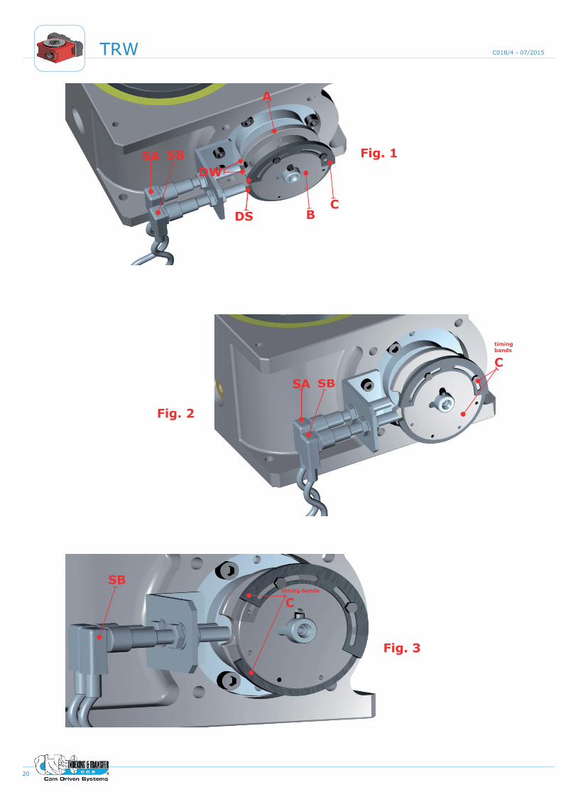
•The signal to stop the motor is made by way of two phase cams A & B and two (2) proximity sensors (PNP n.o.) designated as SA and SB (Fig. 1,2).
•Phase cam A is fixed on the input shaft of the indexer with a key and will have a rounded cutout in the diameter designated as DW. This cutout corresponds with the dwell period of the indexer.
•When the output signal of sensor SA (corresponding to phase cam A) is low, the unit is positioned in dwell DW.
•The second phase cam, noted as phase cam B is adjustable: the gap DS must be adjusted by rotating the timing bands C to be the same width or wider than the rounded cutaway in phase cam A (DW).
•Phase cam B must be used to provide a signal to stop the motor. The adjustable timing bands C of phase cam B allows the sensor SB to detect the dwell position in advance of proximity sensor SA, thereby providing a signal to indicate the indexer is in dwell.
•Diagrams 1 and 2 show the timing sequence and operation.
•When the output signal of sensor SB goes low this must be used to start the deceleration of the motor (diag. 1 #1).
•The motor speed starts to decelerate (diag. 1 #2) and comes to a stop (diag. 1 #3) in the dwell period.
•When the motor has stopped, the output of sensor SA must be low (diag. 1 #4) otherwise the unit has not properly stopped in the dwell phase position (diag. 2 #3). If this happens, you must adjust (make gap wider) the timing bands C of phase cam B as shown in (fig.3) so that the stop signal is detected earlier and again check that the motor is decelerated quickly enough so that it stops in the dwell period. The proximity sensor SA will show the signal is low (motor stopped).
• It is important that the motor speed be managed via a controlled deceleration to stop and not coast to a stop.
Engl
ish
SENSORE PROXY E CAMMA DI FASE
• Il sistema di arresto del motore durante la fase di fermo è composto da due camme di fase A e B e due sensori (PNP n.o.) SA e SB (Fig. 1,2).
•La camma di fase A è solidale con l’albero di ingresso del moto mediante una chiavetta e ha un taglio designato come DW. Questo taglio corrisponde alla fase di fermo dell’index.
•Quando l’uscita del sensore SA (relativo alla camma A) è bassa l’unità è in fase di fermo DW.
•La seconda camma di fase designata come B è regolabile: l’apertura DS deve essere regolata per risultare uguale o maggiore del taglio nella camma A (DW).
•La camma di fase B deve essere usata per fornire il segnale di fermata al motore. Le bande regolabili C della camma di fase B permettono al sensore SB di rilevare la fase di fermo prima del sensore di prossimità SA, il quale segnala che l’index è nella fase di fermo.
• I diagrammi 1 e 2 mostrano la sequenza temporale e le operazioni da effettuare.
•Quando il segnale in uscita del sensore SB diventa basso lo si deve usare per cominciare a decelerare il motore (diag. 1 #1).
• Il motore comincia a decelerare (diag. 1 #2) e si ferma (diag. 1 #3) nella fase di fermo dell’index.
•Quando il motore è fermo, l’uscita del sensore SA deve esser bassa (diag. 1 #4) altrimenti l’unità index non si è arrestata correttamente nella fase di fermo (diag. 2 #3). In questo caso si devono allargare le bande regolabili C della camma di fase B come mostrato in fig. 3 affinché il segnale di stop del motore sia rilevato prima, quindi controllare ancora che il motore deceleri abbastanza velocemente da fermarsi nella fase di fermo. Il sensore di prossimità SA sarà basso con il motore fermo.
•E’ importante che la velocità del motore sia gestita opportunamente.
Ital
iano
PROXIMITY-SENSOR UND PHASENNOCKEN •Das Stoppsystem des Motors mittels
Signal besteht aus zwei (Phasen-) Nocken A und B und zwei Sensoren (PNP n.o.) SA und SB (Abb. 1,2).
•Der Nocken A ist mittels eines Schlüssels fest mit der Eingangswelle der Indexiereinheit verbunden. Auf dem Aussendurchmesser des Nockens A befindet sich eine gerundete Öffnung DW. Diese Öffnung DW zeigt die Stillstands-/Rastphase der Indexiereinheit an.
•Wenn das Ausgangssignal des Sensors SA (bezüglich des Nockens A) niedrig ist, befindet sich die Einheit in der Stillstandsphase/Rastphase DW.
•Auch der zweite (Phasen-) Nocken B hat eine Öffnung am Aussendurchmesser DS, die mittels der Vorrichtung C vergrößert oder verkleinert werden kann. Diese Öffnung DS muss größer oder mindestens gleich der des Nockens A (DW) eingestellt sein.
•Das Stoppsignal für den Motor muss über den (Phasen-) Nocken B und den Sensor SB gegeben werden. Die Einstellung der Öffnung DS mittels der Vorrichtung (C) am Nocken B ermöglicht dem Sensor SB die Stillstands-/Rastphase zeitlich vor dem Näherungssensor SA zu erfassen und dies durch ein Signal anzuzeigen. Dadurch wird ein korrektes Anhalten des Motors in der Stillstands-/Rastphase gewährleistet.
•Die Diagramme 1 und 2 zeigen die Sequenz der Vorgänge.
•Wenn das Ausgangssignal des Sensors SB sich abschwächt bzw. niedrig ist,sollte das Signal zur Verlangsamung bzw. zum Stopp des Motors gegeben werden (Diag. 1 #1).
•Der Motor beginnt langsamer zu werden (Diag. 1 #2) und hält in der Stillstands-/Rastphase an (Diag. 1 #3).
•Wenn der Motor still steht, muss das Ausgangssignal des Sensors SA niedrig sein (diag. 1 #4). Die Einheit ist folglich in der Stillstands-/Rastphase DW (richtige Position). Wenn die Einheit außerhalb der Stillstands-/Rastphase DW (Diag. 2 #3) anhält, ist der Ausgang des Sensors SA hoch (falsche Position). Um dies zu korrigieren, muss man mittels Vorrichtung C die Öffnung DS erweitern (Abb. 3). Damit wird dasStoppsignal des Motors früher erfasst und man stellt sicher, dass der Motor schnell genug verlangsamt wird, um in der Stillstands-/Rastphase zu stoppen. Der Motor beginnt dann die Verlangsamung früher und hält korrekt in der Stillstands-/Rastphase DW der Einheit mit dem niedrigen Sensor SA an.
•Es ist äußerst wichtig die Motorgeschwindigkeit über eine kontrollierte Verlangsamung zu reduzieren, um den Motor zu stoppen. Der Motor darf nicht durch „Auslaufen“ gestoppt werden.
Deu
tsch
19
TRWC018/4 - 07/2015
DETECTEUR DE PROXIMITE ET CAME DE PHASE
•Le système d’arrêt du moteur pendant la phase d’arrêt de l’unité est composé de deux cames A et B et de deux capteurs (PNP n.o.) SA et SB (Fig. 1,2).
•La came A est unie à l’arbre d’entrée du mouvement grâce à une clef. L’ouverture de la came de phase A (DW) n’est pas réglable et est la même que la phase d’arrêt unité.
•Quand la sortie du capteur SA (relatif à la came A) est basse, l’unité est en phase d’arrêt DW.
•La came de phase B est réglable: l’ouverture DS doit être supérieure ou égale à celle de la came A (DW).
•La came B, à travers le capteur SB, commande le signal de stop moteur. Le réglage de cette came permet d’anticiper ou retarder le signal de stop moteur afin de garantir un arrêt correcte du moteur dans la phase d’arrêt de l’unité.
•Les diagrammes 1 et 2 montrent la séquence des opérations.
•Quand l’entrée du capteur SB est basse, on doit envoyer le signal de stop au moteur (diag. 1 #1).
•Le moteur commence à décélérer (diag. 1 #2) et s’arrête (diag. 1 #3).
•Quand le moteur est arrêté, la sortie du capteur SA doit être basse. L’unité est donc en phase d’arrêt. Dans le cas où l’unité s’arrête en dehors de la phase d’arrêt DW (diag. 2 #3), la sortie du capteur SA est haute. Pour corriger cela, on doit agir sur la came B (fig.3) en élargissant l’ouverture DS afin d’anticiper le signal de stop moteur (diag. 1 #1). Le moteur commence la décélération (diag. 1 #2) et s’arrête (diag. 1 #3) correctement dans la phase d’arrêt DW de l’unité avec le capteur SA bas.
Fran
çais
e
SENSORES DE PROXIMIDAD Y LEVA DE FASE
•La señal de parar el motor se realiza por medio de dos levas de fase A y B y dos sensores de proximidad (PNP n.o.), designados como SA y SB (Fig. 1,2).
•La leva de fase A es fija y se monta con chaveta en el eje de entrada. Tiene una apertura en el diámetro exterior designado como DW. Dicha apertura corresponde al período de pausa de la unidad.
•Cuando la señal del sensor SA (correspondiente a la leva A) detecta la apertura, la unidad está en fase pausa DW.
•La leva de fase B es regulable (dos semilevas): la abertura DS debe regularse para que resulte igual o superior a la apertura fija de la leva de fase A (DW).
•La leva de fase B se utiliza para proporcionar una señal de paro al motor. La regulación de la apertura permite al sensor SB anticipar el inicio del paro motor respecto a la del sensor SA, que señala que el sistema está en pausa.
•Los diagramas 1 y 2 muestran la secuencia temporal y las operaciones a efectuar.
•Cuando el sensor SB detecta la apertura de la leva, comienza la desaceleración del motor (diag. 1 #1).
•La velocidad de motor comienza a desacelerar (diag. 1 #2) y se para (diag. 1 #3) en la zona de pausa.
•Cuando el motor se ha parado, la salida de sensor SA también debe detectar el punto de paro (diag.1 #4). Si no es así, el motor no para correctamente (diag. 2 #3). Para corregir esta desviación debe ampliar la apertura de la leva fase B, tal y como se muestra en (fig.3). De este modo, la señal de parada se anticipa. De nuevo compruebe que el motor frena en la zona de parada. El sensor de proximidad SA también indica que la señal de paro es correcta.
•Es importante controlar que la velocidad del motor sea gestionada correctamente.
Espa
ñol
20
TRW C018/4 - 07/2015
Fig. 1
Fig. 2
Fig. 3
SA SB
SA SB
A
DW
DS BC
timing bands
C
timing bands
C
SB

21
TRWC018/4 - 07/2015
SA
SB
MotorSpeed
Indexer Motion Period
Indexer Motion Period
Diagram 1 - Motor properly stopped in dwell period
1
2
3
Diagram 2 - Motor improperly stopped
1
2
3
αs 360°0°
DS
DW
DS
αs 360°0°
IndexerDisplacement
IndexerDisplacement
IndexerDwellPeriod
SA
SB
MotorSpeed
DW
4
IndexerDwellPeriod

22
TRW C018/4 - 07/2015

Your Global Partner for Cam Motion Technology
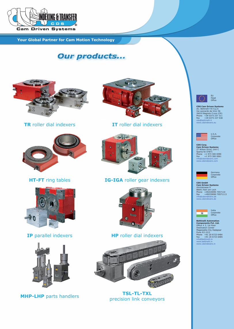
Our products...
TR roller dial indexers IT roller dial indexers
HT-FT ring tables IG-IGA roller gear indexers
IP parallel indexers HP roller dial indexers
MHP-LHP parts handlers TSL-TL-TXL precision link conveyors
EU Head Office
CDS Cam Driven Systems div. Bettinelli F.lli S.p.AVia Leonardo da Vinci 5626010 Bagnolo Cr.sco (CR)Phone +39 0373 237 311Fax +39 0373 237 [email protected]
U.S.A. Corporate Office
CDS Corp.Cam Driven Systems27 Wilson Drive, Unit CSparta NJ 07871 Phone +1 973 300 0090Fax +1 973 300 [email protected]
Germany Corporate Office
CDS GmbHCam Driven SystemsUlrichstrasse 986641 Rain am LechPhone +49(0)9090 7057110Fax +49(0)9090 [email protected]
India Corporate Office
Bettinelli Automation Components Pvt. Ltd.Office # 3, 1st FloorDestination CenterMagarpatta City HadapsarPune 411-013 Phone +91 20 6723 6484Fax +91 20 6723 [email protected]