yolanda becerra, juan josé costa and alex pajuelo course
TRANSCRIPT

1
ZeosYolanda Becerra, Juan José Costa and Alex Pajuelo
Course 2019–2020
F

2
PREFACE
The aim of this document is to guide the design and implementation details of a simple operatingsystem called ZeOS.
The document will describe an initial basic implementation, to which a number of functionalitieswill be added. This basic implementation is responsible for booting up the OS and initialize allthe necessary data structures it requires to control the hardware and start an empty unprivilegedprocess. Both high-level (C) and low-level (assembly) programming languages will be used inorder to add these new functionalities to the system.
The first piece of work to be completed will be on an essential part of any OS: the boot process.This will be followed by a section on the management of some basic interrupt and exceptionhandling. Work will then be undertaken on process management in the OS.
For this document to be understood, the following concepts must be known:
• Input/output mechanisms (exceptions/interrupts/system calls).• Process management (data structures/algorithms/scheduling policies/context switch/related
system calls).• Input/output management (devices/file descriptors).• Subroutines and exceptions.• Memory management.
What you should do with this document
You must first read all the documentation so that you have an overall vision of ZeOS. After that,it is advisable that you follow all the steps described in this document to design and implementsome of the components of the OS such as new data structures, functions, algorithms, etc.

3
CONTENTS
1 PRIOR KNOWLEDGE 6
2 INTRODUCTORY SESSION 6
2.1 Working environment . . . . . . . . . . . . . . . . . . . . . . . . . . . . . . . . . 6
2.2 Getting started . . . . . . . . . . . . . . . . . . . . . . . . . . . . . . . . . . . . . 7
2.3 Introduction to ZeOS . . . . . . . . . . . . . . . . . . . . . . . . . . . . . . . . . 7
2.3.1 ZeOS source code files . . . . . . . . . . . . . . . . . . . . . . . . . . 8
2.3.2 ZeOS binary image . . . . . . . . . . . . . . . . . . . . . . . . . . . . 9
2.4 Boot process . . . . . . . . . . . . . . . . . . . . . . . . . . . . . . . . . . . . . . 10
2.5 Image construction . . . . . . . . . . . . . . . . . . . . . . . . . . . . . . . . . . 11
2.5.1 Bochs . . . . . . . . . . . . . . . . . . . . . . . . . . . . . . . . . . . . 11
2.5.2 Debugging using Bochs . . . . . . . . . . . . . . . . . . . . . . . . . . 12
2.5.3 Frequently used debugging commands . . . . . . . . . . . . . . . . 15
2.6 Work to do . . . . . . . . . . . . . . . . . . . . . . . . . . . . . . . . . . . . . . . 15
2.6.1 Initial steps: Understanding what is being executed . . . . . . . . . 16
2.6.2 User code modification . . . . . . . . . . . . . . . . . . . . . . . . . . 17
2.6.3 Use of assembly . . . . . . . . . . . . . . . . . . . . . . . . . . . . . . 18
2.6.4 System code modification . . . . . . . . . . . . . . . . . . . . . . . . 19
3 MECHANISMS TO ENTER THE SYSTEM 20
3.1 Preliminary concepts . . . . . . . . . . . . . . . . . . . . . . . . . . . . . . . . . 21
3.2 Function name conventions . . . . . . . . . . . . . . . . . . . . . . . . . . . . . 21
3.3 Files . . . . . . . . . . . . . . . . . . . . . . . . . . . . . . . . . . . . . . . . . . . 21
3.4 Hardware management of an interrupt . . . . . . . . . . . . . . . . . . . . . . 22
3.4.1 Task State Segment (TSS) . . . . . . . . . . . . . . . . . . . . . . . . . 22
3.5 Zeos system stack . . . . . . . . . . . . . . . . . . . . . . . . . . . . . . . . . . . 24
3.6 Programming exceptions . . . . . . . . . . . . . . . . . . . . . . . . . . . . . . . 25
3.6.1 Writing the service routines . . . . . . . . . . . . . . . . . . . . . . . 25
3.6.2 Exception parameters . . . . . . . . . . . . . . . . . . . . . . . . . . . 26
3.6.3 Writing the handler . . . . . . . . . . . . . . . . . . . . . . . . . . . . 26
3.6.4 Initializing the IDT . . . . . . . . . . . . . . . . . . . . . . . . . . . . 26
3.7 Programming interrupts . . . . . . . . . . . . . . . . . . . . . . . . . . . . . . . 27
3.7.1 The keyboard interrupt management . . . . . . . . . . . . . . . . . . 27
3.7.2 Writing the service routine . . . . . . . . . . . . . . . . . . . . . . . . 28

4
3.7.3 Writing the handler . . . . . . . . . . . . . . . . . . . . . . . . . . . . 29
3.8 Programming system calls . . . . . . . . . . . . . . . . . . . . . . . . . . . . . . 29
3.8.1 Independence from devices . . . . . . . . . . . . . . . . . . . . . . . 30
3.8.2 Returning results . . . . . . . . . . . . . . . . . . . . . . . . . . . . . 30
3.8.3 Writing the write wrapper . . . . . . . . . . . . . . . . . . . . . . . . 31
3.8.4 Service Routine to the write system call . . . . . . . . . . . . . . . . 31
3.8.5 Copying data from/to the user address space . . . . . . . . . . . . 32
3.8.6 Writing the handler . . . . . . . . . . . . . . . . . . . . . . . . . . . . 32
3.8.7 IDT initialization . . . . . . . . . . . . . . . . . . . . . . . . . . . . . . 34
3.9 Programming fast system calls . . . . . . . . . . . . . . . . . . . . . . . . . . . 34
3.9.1 Writing the wrapper . . . . . . . . . . . . . . . . . . . . . . . . . . . 35
3.9.2 Writing the handler . . . . . . . . . . . . . . . . . . . . . . . . . . . . 36
3.9.3 Initializing fast system calls . . . . . . . . . . . . . . . . . . . . . . . 36
3.10 Work to do . . . . . . . . . . . . . . . . . . . . . . . . . . . . . . . . . . . . . . . 37
3.10.1 Complete Zeos Code . . . . . . . . . . . . . . . . . . . . . . . . . . . 37
3.10.2 Clock management . . . . . . . . . . . . . . . . . . . . . . . . . . . . 37
3.10.3 Gettime system call . . . . . . . . . . . . . . . . . . . . . . . . . . . . 39
4 BASIC PROCESS MANAGEMENT 40
4.1 Prior concepts . . . . . . . . . . . . . . . . . . . . . . . . . . . . . . . . . . . . . 40
4.2 Definition of data structures . . . . . . . . . . . . . . . . . . . . . . . . . . . . . 40
4.2.1 Process data structures . . . . . . . . . . . . . . . . . . . . . . . . . . 40
4.2.2 Process identification . . . . . . . . . . . . . . . . . . . . . . . . . . . 43
4.3 Memory management . . . . . . . . . . . . . . . . . . . . . . . . . . . . . . . . . 43
4.3.1 MMU: Paging mechanism . . . . . . . . . . . . . . . . . . . . . . . . 44
4.3.2 The directory and page table . . . . . . . . . . . . . . . . . . . . . . 44
4.3.3 Translation Lookaside Buffer (TLB) . . . . . . . . . . . . . . . . . . . 46
4.3.4 Specific organization for ZeOS . . . . . . . . . . . . . . . . . . . . . 47
4.4 Initial processes initialization . . . . . . . . . . . . . . . . . . . . . . . . . . . . 50
4.4.1 Idle process . . . . . . . . . . . . . . . . . . . . . . . . . . . . . . . . . 50
4.4.2 Init process . . . . . . . . . . . . . . . . . . . . . . . . . . . . . . . . . 51
4.4.3 Zeos implementation details . . . . . . . . . . . . . . . . . . . . . . . 52
4.5 Process switch . . . . . . . . . . . . . . . . . . . . . . . . . . . . . . . . . . . . . 53
4.5.1 Initial testing . . . . . . . . . . . . . . . . . . . . . . . . . . . . . . . . 54
4.6 Process creation and identification . . . . . . . . . . . . . . . . . . . . . . . . . 54
5
4.6.1 getpid system call implementation . . . . . . . . . . . . . . . . . . . . 54
4.6.2 fork system call implementation . . . . . . . . . . . . . . . . . . . . . 54
4.7 Process scheduling . . . . . . . . . . . . . . . . . . . . . . . . . . . . . . . . . . 56
4.7.1 Main scheduling functions . . . . . . . . . . . . . . . . . . . . . . . . 56
4.7.2 Round robin policy implementation . . . . . . . . . . . . . . . . . . 57
4.8 Process destruction . . . . . . . . . . . . . . . . . . . . . . . . . . . . . . . . . . 57
4.9 Statistical information of processes . . . . . . . . . . . . . . . . . . . . . . . . . 58
4.10 Work to do . . . . . . . . . . . . . . . . . . . . . . . . . . . . . . . . . . . . . . . 60
5 ACKNOWLEDGEMENTS 60
Appendix 61

6
1 PRIOR KNOWLEDGE
For this document to be understood, it is assumed that you have acquired knowledge from othercourses and that you are able to work in specific environments, specifically:
• Use a Linux environment.• Write programs using the C language.• Write programs using the Linux i386 assembly language.• Add assembly code to a C file.• Modify a Makefile to add new rules or modify existing ones.
If you lack any of these skills, you should find additional information to that given on thiscourse. The information in the bibliography section on the course’s web page may also be useful.
2 INTRODUCTORY SESSION
The main objectives of this section are:
• Become familiar with the working environment.• Learn about the tools that must be used.• Start analyzing and modifying the ZeOS code.• Learn Bochs basic commands.• Refresh some of the concepts needed.
2.1 Working environment
When developing an operating system, you need a working environment usually offered byanother operating system. In this case, to develop ZeOS we will use an Ubuntu system with thefollowing configuration:
• OS. Ubuntu 16.041
• Compiler. GCC 4.x• Emulator. Bochs version 2.6.7 (bochs.sourceforge.net)
This environment will enable you to generate the ZeOS operating system. Once ZeOS has beengenerated, it can be used to boot your computer (after copying it to a floppy disk). However, youshould bear in mind that the system will be recompiled and loaded many times, so it is advisableto run your system on an architecture emulator (like Bochs) in order to save time. This way, whenmodifications are necessary, only the emulator has to be rebooted rather than the computer.
Whenever you need to compress and extract your files use the following commands:
• Compress:
$ tar czvf file_name.tar.gz file_list_to_compress
• Extract:
$ tar xzvf file_name.tar.gz
These commands use tar and gzip at the same time.
In Ubuntu, you will be able to work with several editors (GVim, emacs, nedit, etc.).
1. The system has the user alumne and password sistemes.
7
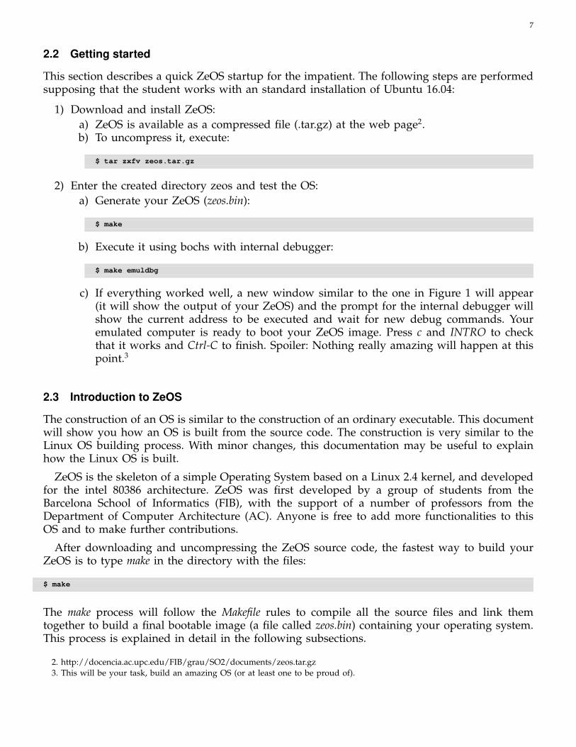
2.2 Getting started
This section describes a quick ZeOS startup for the impatient. The following steps are performedsupposing that the student works with an standard installation of Ubuntu 16.04:
1) Download and install ZeOS:a) ZeOS is available as a compressed file (.tar.gz) at the web page2.b) To uncompress it, execute:
$ tar zxfv zeos.tar.gz
2) Enter the created directory zeos and test the OS:a) Generate your ZeOS (zeos.bin):
$ make
b) Execute it using bochs with internal debugger:
$ make emuldbg
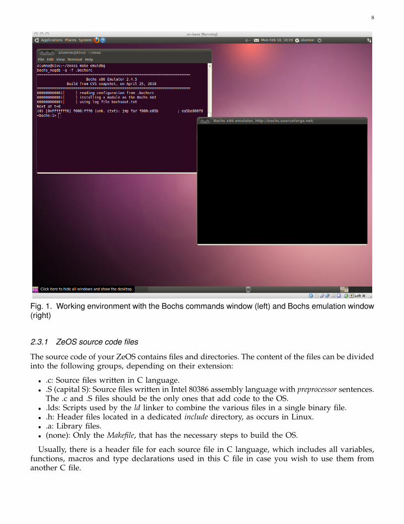
c) If everything worked well, a new window similar to the one in Figure 1 will appear(it will show the output of your ZeOS) and the prompt for the internal debugger willshow the current address to be executed and wait for new debug commands. Youremulated computer is ready to boot your ZeOS image. Press c and INTRO to checkthat it works and Ctrl-C to finish. Spoiler: Nothing really amazing will happen at thispoint.3
2.3 Introduction to ZeOS
The construction of an OS is similar to the construction of an ordinary executable. This documentwill show you how an OS is built from the source code. The construction is very similar to theLinux OS building process. With minor changes, this documentation may be useful to explainhow the Linux OS is built.
ZeOS is the skeleton of a simple Operating System based on a Linux 2.4 kernel, and developedfor the intel 80386 architecture. ZeOS was first developed by a group of students from theBarcelona School of Informatics (FIB), with the support of a number of professors from theDepartment of Computer Architecture (AC). Anyone is free to add more functionalities to thisOS and to make further contributions.
After downloading and uncompressing the ZeOS source code, the fastest way to build yourZeOS is to type make in the directory with the files:
$ make
The make process will follow the Makefile rules to compile all the source files and link themtogether to build a final bootable image (a file called zeos.bin) containing your operating system.This process is explained in detail in the following subsections.
2. http://docencia.ac.upc.edu/FIB/grau/SO2/documents/zeos.tar.gz3. This will be your task, build an amazing OS (or at least one to be proud of).
8
Fig. 1. Working environment with the Bochs commands window (left) and Bochs emulation window(right)
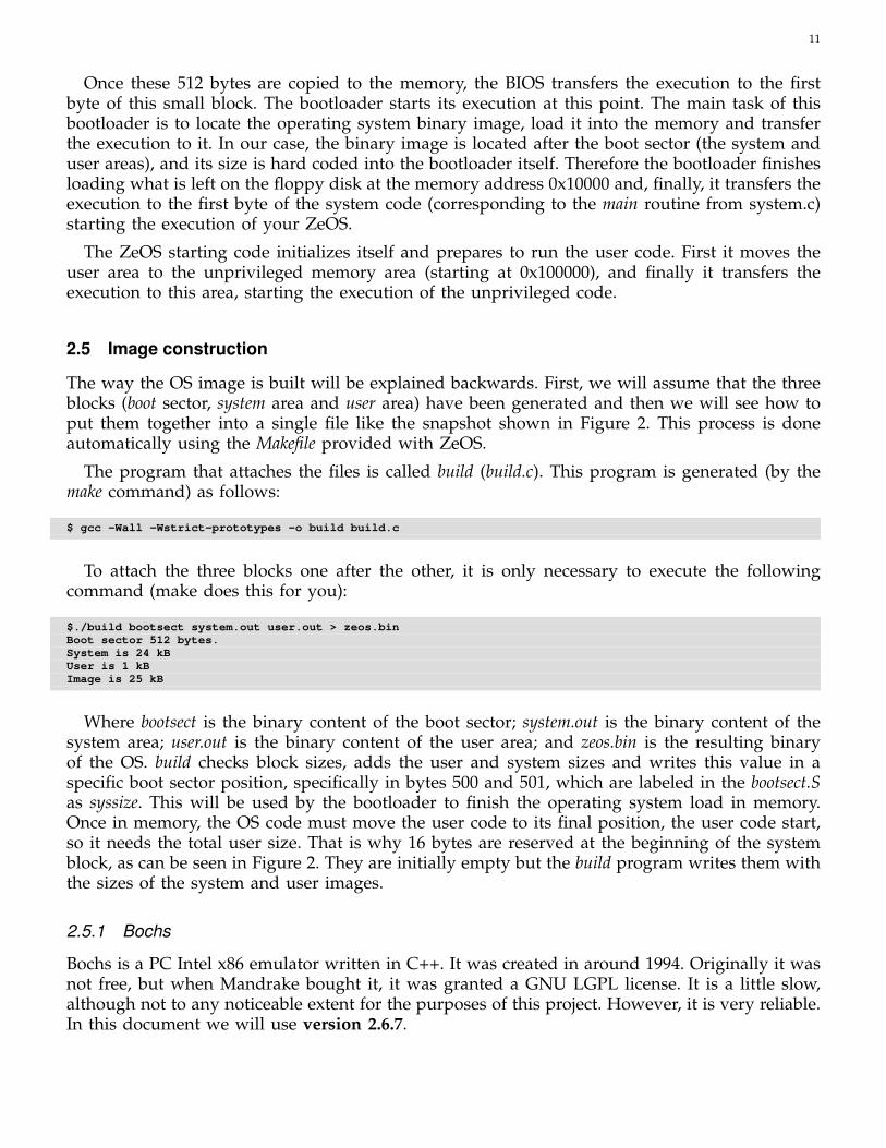
2.3.1 ZeOS source code files
The source code of your ZeOS contains files and directories. The content of the files can be dividedinto the following groups, depending on their extension:
• .c: Source files written in C language.• .S (capital S): Source files written in Intel 80386 assembly language with preprocessor sentences.
The .c and .S files should be the only ones that add code to the OS.• .lds: Scripts used by the ld linker to combine the various files in a single binary file.• .h: Header files located in a dedicated include directory, as occurs in Linux.• .a: Library files.• (none): Only the Makefile, that has the necessary steps to build the OS.
Usually, there is a header file for each source file in C language, which includes all variables,functions, macros and type declarations used in this C file in case you wish to use them fromanother C file.

9
Fig. 2. The three main blocks (bootloader, system and user) forming the ZeOS binary image.4
2.3.2 ZeOS binary image
After the make process you should obtain a single file called zeos.bin with the bootable image ofyour ZeOS.
This file is divided in three main blocks (as shown in Figure 2):
1) The boot sector block. This block only comprises one file (bootsect.S) corresponding to thebootloader. It must weigh exactly 512 bytes, since it has to fit in a single sector.
2) The system area block. This block contains the main files of the OS. This block will beplaced in a part of the memory that guarantees its execution with the processor’s maximumprivilege level. It will offer services to access the hardware and others.
3) The user area block. This block has the user program. The code inside is executed bythe processor with a minimum privilege level. Therefore, it will ask the operating system(through system calls) to access any hardware or other system services that are privileged.
One may ask why the user program is attached to the OS when this actually never happens.User programs are usually found on a hard disk inside a file system in a directory of this filesystem. The simple answer is that currently there is not either file system or an executable loader.Therefore, the user program is attached to the OS (in a position that is easy to calculate), and it iscopied from its location in the image to a memory area with user privileges to which executionis transferred.
4. Some of the file names that appear in Figure 2 may not match the ones from your currently downloaded source code.

10
ENTRY(main)SECTIONS{
. = 0x10000; /* system code begins here */
.text.main :{ BYTE(24); /* reserved to store user code management data */
*(.text.main) }.text : {*(.text) }.rodata : { *(.rodata) }.data : { *(.data) } /* Initialized data */.bss : { *(.bss) } /* Not initialized data */. = ALIGN(4096); /* task_structs array aligned to page */.data.task : { *(.data.task) }
Fig. 3. system.lds file. Linker script file for the system image.
union task_union task[NR_TASKS] __attribute__((__section__(".data.task")));
Fig. 4. Task_struct array annotated with the section .data.task (sched.c)
Figure 3 shows the contents of the system.lds file that enables the linker to locate on the memorythe various sections of an executable file. In this case, it sets the starting address (0x10000) of thesystem code; reserves 24 bytes, using the BYTE directive, corresponding to 3 integers to storethe system image size, the user image size and some extra bytes reserved for future use; thenthe system code (.text); the read-only data section (.rodata); the initialized data (.data); the noninitialized data (.bss); and, finally, it leaves a gap to align the current address to a page-size (4096bytes) address and adds a special section (.data.task) wich will contain the task_struct array.
2.4 Boot process
The blocks boot, system and user (described in the previous section) are appended to each otherto create a single binary format file with the content of all ZeOS operating system. This file maybe copied to an unformatted floppy disk5, beginning at sector 0, and any computer booting thisfloppy disk would start our ZeOS automatically.
The boot process is simple. After turning on your computer (before the OS is executed) aprogram is placed in a read only memory (ROM) area and it will be executed, called the BIOS.This program checks that the PC is working properly. 6 It then looks for the preconfigured bootingdevice and tries to access it. It does so by loading the initial sector from this device (sector 0) intothe memory. It does not matter whether the device is a floppy disk, a hard disk, or a CD-ROM.
As the size of the first sector that the BIOS loads is quite small (512 bytes), there is not enoughspace to store the entire ZeOS. It is only possible to store a loader (the bootloader). This bootloaderis designed to fit into these 512 bytes and the BIOS just loads them into the memory at a hardcoded address (0x7C00).
5. For historical reasons... just look here https://en.wikipedia.org/wiki/Floppy_disk :)6. You can see how the memory, the disk and other devices are checked during this process.
11
Once these 512 bytes are copied to the memory, the BIOS transfers the execution to the firstbyte of this small block. The bootloader starts its execution at this point. The main task of thisbootloader is to locate the operating system binary image, load it into the memory and transferthe execution to it. In our case, the binary image is located after the boot sector (the system anduser areas), and its size is hard coded into the bootloader itself. Therefore the bootloader finishesloading what is left on the floppy disk at the memory address 0x10000 and, finally, it transfers theexecution to the first byte of the system code (corresponding to the main routine from system.c)starting the execution of your ZeOS.
The ZeOS starting code initializes itself and prepares to run the user code. First it moves theuser area to the unprivileged memory area (starting at 0x100000), and finally it transfers theexecution to this area, starting the execution of the unprivileged code.
2.5 Image construction
The way the OS image is built will be explained backwards. First, we will assume that the threeblocks (boot sector, system area and user area) have been generated and then we will see how toput them together into a single file like the snapshot shown in Figure 2. This process is doneautomatically using the Makefile provided with ZeOS.
The program that attaches the files is called build (build.c). This program is generated (by themake command) as follows:
$ gcc -Wall -Wstrict-prototypes -o build build.c
To attach the three blocks one after the other, it is only necessary to execute the followingcommand (make does this for you):
$./build bootsect system.out user.out > zeos.binBoot sector 512 bytes.System is 24 kBUser is 1 kBImage is 25 kB
Where bootsect is the binary content of the boot sector; system.out is the binary content of thesystem area; user.out is the binary content of the user area; and zeos.bin is the resulting binaryof the OS. build checks block sizes, adds the user and system sizes and writes this value in aspecific boot sector position, specifically in bytes 500 and 501, which are labeled in the bootsect.Sas syssize. This will be used by the bootloader to finish the operating system load in memory.Once in memory, the OS code must move the user code to its final position, the user code start,so it needs the total user size. That is why 16 bytes are reserved at the beginning of the systemblock, as can be seen in Figure 2. They are initially empty but the build program writes them withthe sizes of the system and user images.
2.5.1 Bochs
Bochs is a PC Intel x86 emulator written in C++. It was created in around 1994. Originally it wasnot free, but when Mandrake bought it, it was granted a GNU LGPL license. It is a little slow,although not to any noticeable extent for the purposes of this project. However, it is very reliable.In this document we will use version 2.6.7.

12
Execution
The Bochs executable is /usr/local/bin/bochs. This will read a configuration file to prepare theemulated computer and will start its execution.
Bochs configuration file
Bochs uses a file to configure the features of the emulated computer7. We will focus on thefollowing three features:
• Image location. Line 5 defines a floppy disk drive with the image file to be inserted. Theimage file must correspond to the path that points to the zeos.bin. Currently it is set to loadthe image zeos.bin from the current directory.
floppya: 1_44= ./zeos.bin, status=inserted
• Boot device. Line 6 defines the device used to boot the emulated computer. In our case, thefloppy device.
boot: floppy
By default, Bochs assumes a default configuration file named .bochsrc. But, you can use the -foption in order to use another configuration file8:
$ bochs -f .bochsrc_gdb -q
2.5.2 Debugging using Bochs
In order to debug your operating system, it is necessary to control execution using a debugger.Bochs offers two options for debugging code: (1) using GDB as an external debugger or (2) usingan internal debugger that is part of the emulator. Both options are exclusive, and therefore there aretwo different executable files available in the laboratory (bochs and bochs_nogdb). You can choosethe best version taking into account that:
• GDB is more suitable to debug high-level programming problems (not related with theunderlying hardware).
• The internal debugger is recommended when you want to debug specific information aboutthe emulated hardware (namely physical addresses translation, special registers, . . . ).
In summary, use GDB version (bochs) and use the Bochs internal debugger (bochs_nogdb) onlywhen everything else fails.
Controlling execution through internal Bochs debugger
To start the Bochs internal debugger you can use:
$ make emuldbg
7. The details on the different options used may be find at http://bochs.sourceforge.net/doc/docbook/user/bochsrc.html8. The target gdb from the Makefile uses this option.

13
Once executed, you should see two windows like the ones shown in Figure 1: the emulationwindow (where the output to the screen device will be shown) and the Bochs window with aprompt (where debug commands may be inserted).
Under the hood the previous command is following the next steps:
• Compile the ZeOS code with debug symbols, using GCC with the "-g" flag (which is enabledby default in the Makefile).
• Execute Bochs with internal debugger enabled using the default configuration file (.bochsrc).
$ bochs_nogdb -q
The commands window displays a prompt (<bochs:1>)in which commands can be introduced.This prompt shows information about the memory address that is about to execute (correspond-ing to the register EIP content, ’0xfffffff0’ in this case) and its memory content (showing alsoits translation to an assembly instruction, ’jmp far f000:e05b’ in this case). A summary of thecommands that can be executed may be found at http://bochs.sourceforge.net/doc/docbook/user/internal-debugger.html.
Controlling execution through an external GDB debugger
In order to start the GDB debugger you can use:
$ make gdb
Figure 5 shows the windows appearing with this command: the emulation window, the Bochswindow and the GDB window with its prompt9 ready to accept commands (add breakpoints,continue the program execution, etc). You can find some help on debug commands in sec-tion 2.5.3 or the GDB reference guide with all the GDB commands on the following link: https://sourceware.org/gdb/download/onlinedocs/
Under the hood the previous command follows the steps below:
• Compile the ZeOS code with debug symbols, using GCC with the "-g" flag (which is enabledby default in the Makefile).
• Execute Bochs with support for the external debugger and load the configuration file thatenables debugging with GDB (.bochsrc_gdb):
$ bochs -f .bochsrc_gdb -q
– In this file the option for External debugger configuration is added. When Bochs iscompiled with GDB support, it starts the emulation with debug disabled. In order touse GDB it is necessary to add the following line to the configuration file:
gdbstub: enabled=1, port=1234, text_base=0, data_base=0, bss_base=0
This option instructs Bochs to start the emulation and wait for a connection at port 1234from a GDB session to control the execution. It should be highlighted that this line is
9. At the GDB prompt you may want to switch to the gdbTUI using the combination ’C-x a’. Look for more information athttps://sourceware.org/gdb/onlinedocs/gdb/TUI.html

14
Fig. 5. Bochs commands windows (up), Bochs emulation window (right) and GDB window (down)after establishing a connection between GDB and Bochs.
only interpreted when the Bochs is compiled to use the external debugger. Otherwise, itwill complain with an error about the lack of external debugger support.
The Bochs virtual machine will start (opening the emulation window) and will wait for theconnection request from GDB.
• After executing Bochs, a new terminal is needed to execute GDB.10 GDB accepts a programfilename as the argument to be debugged, and it automatically loads all the symbols of thisprogram. Therefore, start GDB to debug the system part of our Zeos:
$ gdb system
• Connect GDB to the Bochs instance by executing the command below in GDB (the portshould be the same as the one used in .bochsrc_gdb).
(gdb) target remote localhost:1234
10. Instead of GDB you can use any front-end to GDB, like DDD or gdbTUI.

15
• And, finally, load the remaining symbols for the user part.
(gdb) add-symbol-file user
2.5.3 Frequently used debugging commands
The gdb manual page (man gdb) is a good starting point for someone new to debugging applica-tions, explains how to use it to debug a program and a list of the most frequently used commands.Table 1 presents, for reference, some of the most frequently used commands for Bochs and GDBdebuggers. Also you could find online tutorials on GDB.11
Bochs GDB Descriptionhelp help Show help about the commands that can be executed. Usually this accept a
command to show more specific help.Control flowcontinue continue Execute the image normally until the next breakpoint (if you have one). While
executing the image, you can not issue new debugger commands, so in orderto stop the execution you should press the Ctrl-C key combination, and thedebugger prompt will appear again.
step [num] stepi | si Execute a single assembly instruction. If num is provided, execute this numberof instructions.
(not available) step Execute a single high level instruction (C).next nexti | ni Execute a single assembly instruction stepping over subroutines. If the in-
struction is a call to a subroutine, the whole subroutine is executed (instead ofsimply executing the instruction) and execution stops at the instruction afterthe call instruction.
(not available) next Execute a single high level instruction (C) stepping over subroutines.break address b *address
b functionInsert a breakpoint in the instruction indicated in the address. The address canbe written in decimal (123459), octal (0123456) or, as is usual, in hexadecimal(0x123abc). For example, if you write "b 0x100000" (or "b *0x100000" in GDB),it will insert a breakpoint in the first code line of the user process. GDB alsoaccepts a function name or a specific location in a file (filename:linenumber).
Data examinationr info r Show the content of the hardware registers.x addr x addr Examine memory content at address addr.print-stack [num_words] x/16 $esp Print num_words from the top of the stack. By default, only 16 values are
shown. It is only reliable if you are in system mode, when the base addressof the stack segment is 0.
(not available) print expr Display the value of an expression or C variable.(not available) bt Backtrace: Display the program stack frame12for each active subroutine.(not available) frame number Select a specific frame number.info tab (not available) Show current address translation (Logical -> Physical).quit quit Exit debugger.
TABLE 1Frequently used commands for Bochs and GDB.
2.6 Work to do
In order to familiarize with the environment is adviseable to carefully follow and try the stepsdescribed in this section. You will learn how to:
11. Like Beej’s Quick Guide to GDB at http://beej.us/guide/bggdb/ showing a sample GDB session (really useful).12. You can find an example of stack frames at https://sourceware.org/gdb/download/onlinedocs/stack_frame.pdf.gz

16
• Generate the ZeOS image.• Visualize the generated object code (user and system).• Relate variables and functions from code to its location in memory (and the other way
around).• Use the debugger to control the execution of your code and view information about data
and some hardware content (memory and registers).• Modify the user code.• Mix assembly and C routines in your code.
2.6.1 Initial steps: Understanding what is being executed
In this section you will prove that after invoking Bochs to run the ZeOS image, ZeOS is beingloaded in memory, initialized and it starts the execution of the user process which executes aninfinite loop. To do that you must:
1) Generate the ZeOS image.2) Examine the generated output of the make command. Look at the different commands used
and their flags (the man command may be useful to understand them) and try to relate thegenerated files with the different areas shown in Figure 2.
3) Run the generated image. For that, you will start the bochs debugger.13
4) ZeOS should start, initialize itself, and start an user process. After the message stating"Entering user mode" it seems that ZeOS hangs or it is doing nothing. Therefore, where isZeOS hanged?, which assembly instruction is executing?
5) Where is the previous instruction located in the code?• To interpret the code execution, we need to locate this memory address into the code
section of the generated image. For that, the commands objdump and nm can be used14.• The objdump command shows the compiler-generated assembly code, its instruction
encoding, and their corresponding memory addresses, which can be useful to insertbreakpoints (Figure 6 shows the result of using objdump with the system file, where thecontent of the C function main is shown).
• The nm command shows the symbols (variables and functions names) present in anobject file and their memory locations. For instance, Figure 7 shows that, for example,there is an initialized variable (D) task (the task struct array) located at address 0x11000.
13. Remember, as stated in Table 1, that continue starts the execution and Ctrl-C stops it.14. Look at their manuals for extra documentation, especially you should look for -d, -h and -S flags in objdump and -n flag in
nm.

17
00010000 <main-0x4>:10000: 10 00 adc %al,(%eax)
...00010004 <main>:
10004: 55 push %ebp10005: 89 e5 mov %esp,%ebp10007: 83 ec 08 sub $0x8,%esp1000a: 83 e4 f0 and $0xfffffff0,%esp1000d: 6a 00 push $0x01000f: 9d popf10010: ba 18 00 00 00 mov $0x18,%edx10015: b8 18 00 00 00 mov $0x18,%eax1001a: fc cld1001b: 8e da mov %edx,%ds1001d: 8e c2 mov %edx,%es1001f: 8e e2 mov %edx,%fs
...
Fig. 6. "objdump -d system" output sample
0001042c T set_ss_pag00010224 T set_task_reg000102b8 T setTrapHandler000100f8 T setTSS00011000 D task0001c000 D taula_pagusr0001d020 B tss00010538 D usr_main0001d8a0 B x00010544 D y
Fig. 7. "nm system" output sample
2.6.2 User code modification
At this point we are ready to modify the user part with some code. Currently the OS does notoffer any service15, therefore the user application is very simple. The user.c file is the place inwhich we will write the user code. We strongly recommend that you only modify this file fornow.
• Add to the user.c file a new function add that returns the sum of its two parameters. Thisfunction has the following header:
int add(int par1,int par2);
• Modify the main() of the user.c file to add a call to the previous function with some dummyvalues (like 0x42 and 0x666) and store the resulting value in a local variable.
• Generate a new ZeOS image. Correct any errors that may appear and check for any warnings
15. This means that you can NOT use any of the libc functionalities (like printf ), but you will add these features soon.

18
when it is compiled (a new warning must appear!).16
• Execute the command "objdump -d user.o" to see the generated assembly code for the file user.c.Note that the addresses begin at zero as it is an object file.
– Can you see the generated code of the function add?.• Now look at the resulting executable file, execute "objdump -d user". Do the addresses match the
previous object file? Why?• Run the whole program in the bochs debugger (continue command). To regain control in the
debugger you have to type Ctrl+C. After doing so, which line is going to be executed?.• As there is no output feedback, we will re-execute the program with breakpoints. To do this,
at the debugger prompt set a BREAKPOINT at the first instruction of the main routine andanother one at the add routine. Now that they are set, we could continue the execution usingthe continue command, but these breakpoints are already passed, and therefore we need torestart the bochs emulator. At the upper right zone of the bochs Window there is a buttonnamed reset to do exactly this. Check that the execution stops at the first breakpoint. Then,continue the code execution and try to arrive to the 2nd breakpoint (Spoiler: it is not possible).
– Take a look at the dissasemble code from user file again. Can you see the invoking callto the function add?. Take a look at the flags used to generate this file and try to explainthis behavior. Can you solve the problem?
• After solving the previous issue. Re-execute a part of the program step by step. To do this,set the breakpoint at the add routine and when arrived, use the commands step and/or nextto move the execution forward17 and examine the memory content, the stack or the registers.
Note: Adding a BREAKPOINT is often the only useful way to reach to a subroutine address.For example, after entering a loop with a high number of iterations, and you want to get outof it. In this case, the number of STEP commands that may be needed to get out of the routinewould be extremely high.
2.6.3 Use of assembly
Let’s add new files to our user application using some assembly.
• Examine the generated assembly code for the add function and its invocation.– How is the dynamic link generated?– How are the parameters accessed?– How is the result returned?
• Create a new function addAsm in assembly with the same goal: receive two parameters,add them and return the resulting value (the important thing is that it must follow the Cconvention to be called from a C program):
– Create a new file for user assembly code: suma.S.– Define the function addAsm using the ENTRY macro18 (defined in include/asm.h). This
macro helps to define a function header as shown in Figure 8.– Modify Makefile to:
∗ preprocess the file and generate a suma.s file (similar to entry.s target).
16. The warnings do not stop the compilation, but they are a sign that something weird happens and it needs extra care. Anideal compilation phase would show no warnings, and therefore any change in the code that produces a warning will be easilyspotted –otherwise it may be hidden in a ton of already ignored warnings–. After this session try to remove them all.
17. It has been seen that after stopping at a breakpoint with GDB and Bochs v2.6.7, it is unable to continue the execution withthe debugger instructions step or next. Therefore you must use the commands stepi, nexti or continue.
18. You can check the bibliography for preprocessor macros documentation.

19
#include <asm.h>
ENTRY(addASM)/* your assembly instructions separated by newlines (\n) */
Fig. 8. Example showing how to define the assembly function ’addASM’ with the ENTRY macro.
∗ assemble this file and add it to the list of files to be linked for the user image (similarto entry.o target).
• Add a call to the new assembly function addAsm in the main function of the user.c file byputting the result of the addition in a local variable. As the function is in a different file,we must instruct the C compiler to recognize the assembly function by adding a headerfor it. This header gives the compiler all the information it needs (number and type of theparameters, and the resulting type) and the linker will finish the work linking the functioncall to its real code.
• Check with the debugger that this assembly version works correctly.• Which address did you enter in the Bochs debugger to access the variable that stores the
resulting value from the add function?
2.6.4 System code modification
The previous sections have shown how to modify the user application, let’s look at the operatingsystem code.
• The entry point of your operating system is the main routine in the system.c file. Skim itscontent and observe that there are a couple of calls to a printk routine that prints a messagein the screen.
• Add some message (like your group identifier) to be printed at the beginning of your OS.• Find the printk code and try to understand what is it doing. The screen device is a memory
mapped device. 19 In particular, the text mode offered by this device consists on a matrixof 25 rows by 80 columns located at a specific memory address (0xb8000). Each cell of thismatrix contains two bytes, the character and its color attributes. As the operating system isexecuting in a privileged level, it can access the required memory addresses to access thescreen hardware device (in this case a memory mapped device).
• To understand the different privilege levels, try to replicate the printc, printk and any neededvariables into the user code and make a call to printk from the main routine to show a "Helloworld" message in the user code. (Spoiler: it will NOT work, but you will learn what happenswhen trying to access directly a hardware device from user mode.)
• You may remove the previous modifications as they will not be needed anymore.• As an OPTIONAL challenge, add a new printc_color routine, similar to printc, that changes
the foreground color of the printed character.• As an OPTIONAL challenge, try to modify the system printc function to scroll the screen
content if the cursor surpases the maximum coordinates instead of the current implementationthat starts again at the first row.
19. A better explanation about the screen device may be found online, for example at Chapter 23 of The Art of Assembly fromRandall Hyde (http://www.plantation-productions.com/Webster/www.artofasm.com/DOS/ch23/CH23-1.html#HEADING1-0).
20
3 MECHANISMS TO ENTER THE SYSTEM
Once the operating system boots, it gets control of all the hardware, and transfers the executionto the user application lowering its execution level to a non-privileged one. Therefore, in orderto execute any privileged code we need a special mechanism to invoke it: the mechanisms to enterthe system.
We will use the interrupt mechanism to execute code from the OS again. Interrupts are eventsthat break the sequential execution of a program and they call a specific handler to solve thesituation. These interrupts can be classified as synchronous or asynchronous depending on whogenerates them:
• Synchronous interrupts are generated by the CPU, at the end of the execution of an instruc-tion.
• Asynchronous interrupts are generated by other hardware devices.
From now on, we will refer to synchronous interrupts as exceptions and to asynchronousinterrupts as interrupts, although both follow the same mechanism.
Intel hardware provides the Interrupt Descriptor Table (IDT) to associate each interrupt withits specific function code. Each interrupt — identified by a number between 0 and 255 — has anentry in this table. Among other data, it contains the address of the routine to be executed (thehandler) and the minimum privilege level needed to execute it.
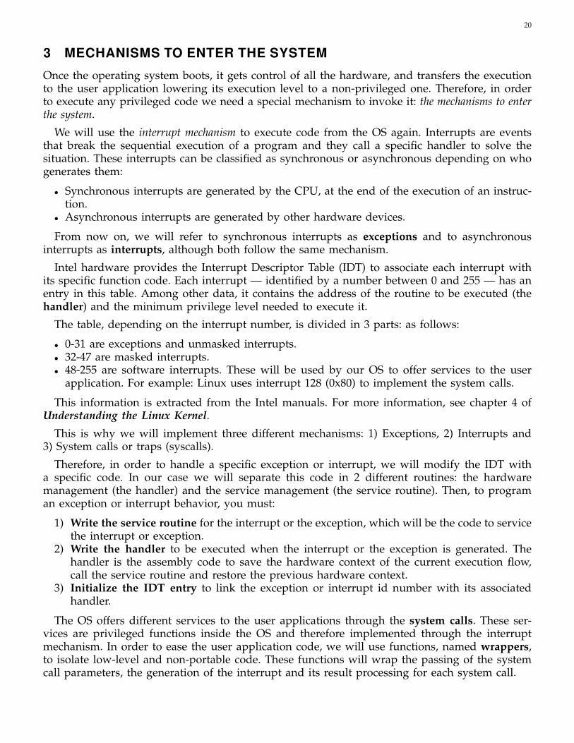
The table, depending on the interrupt number, is divided in 3 parts: as follows:
• 0-31 are exceptions and unmasked interrupts.• 32-47 are masked interrupts.• 48-255 are software interrupts. These will be used by our OS to offer services to the user
application. For example: Linux uses interrupt 128 (0x80) to implement the system calls.
This information is extracted from the Intel manuals. For more information, see chapter 4 ofUnderstanding the Linux Kernel.
This is why we will implement three different mechanisms: 1) Exceptions, 2) Interrupts and3) System calls or traps (syscalls).
Therefore, in order to handle a specific exception or interrupt, we will modify the IDT witha specific code. In our case we will separate this code in 2 different routines: the hardwaremanagement (the handler) and the service management (the service routine). Then, to programan exception or interrupt behavior, you must:
1) Write the service routine for the interrupt or the exception, which will be the code to servicethe interrupt or exception.
2) Write the handler to be executed when the interrupt or the exception is generated. Thehandler is the assembly code to save the hardware context of the current execution flow,call the service routine and restore the previous hardware context.
3) Initialize the IDT entry to link the exception or interrupt id number with its associatedhandler.
The OS offers different services to the user applications through the system calls. These ser-vices are privileged functions inside the OS and therefore implemented through the interruptmechanism. In order to ease the user application code, we will use functions, named wrappers,to isolate low-level and non-portable code. These functions will wrap the passing of the systemcall parameters, the generation of the interrupt and its result processing for each system call.

21
The user code invokes any of these wrappers — as any other user function call — causing theactual entrance into the system, the execution of the system service, and obtaining its result back.
In this section you will find:
• Hardware management of an interrupt.• Code to manage exceptions.• Code to manage the keyboard interrupt.• Code to implement system calls.• Code to implement the write system call.
The following sections include a how-to guide to add an exception, an interrupt and a systemcall to your OS. Remember that these mechanisms — even they are described separately in thisguide — are almost the same, since they are all managed by the same interrupt mechanism(the IDT).
3.1 Preliminary concepts
• Interruption, exception and system call.• Context of a process.• Hardware management of an interrupt.• Checking parameters and returning results in a function.
3.2 Function name conventions
The functions will be given similar names to make the code easier to follow. The handler foran interrupt will be given the same name as the interrupt followed by _handler and the routineservices will be given the same name as the interrupt or exception, followed by _routine. Forexample, the handler name of the exception divide error will be divide_error_handler and its routineservice name will be named divide_error_routine.
As regards the system calls, the handler will be named system_call and the service routineswill be sys_namesyscall, where namesyscall corresponds to the specific system call name (for exam-ple sys_write).
3.3 Files
ZeOS files generally have functions that share a common objective or type. The main files (prob-ably not the only ones) in this section are:
• system.c: System initialization (main)• entry.S: Entry points to the system (handlers)• interrupt.c: Interruption service routines and exceptions• sys.c: System calls• device.c: Device dependent part of the system calls• wrappers.S: System call wrappers• libc.h: System call headers• libc.c: Other user level code provided by the OS (perror, errno, ...)• io.c: Basic management of input/output

22
3.4 Hardware management of an interrupt
Once the system has been initialized, the hardware automatically performs the following stepswhen an interrupt has been generated (for more information, see Understanding the Linux Kernel):
• Determine the i index of the interrupt vector and access the corresponding IDT entry.• Verify that the interrupt has enough privileges to execute the handler, by comparing the
current privilege level with the one stored in the IDT entry. If access is unauthorized itgenerates a general protection exception.
• Check the privilege level of the handler routine to see if it is different from the currentexecution level — our case — in which case the stack will have to be changed.
• Change from the current user stack to the system stack, the hardware obtains the address ofthe system stack to be used from the Task State Segment (TSS) through the SS and the ESP0fields. Then the hardware saves in this new stack: 1) the current content of the SS and ESPregisters (they point to the top of the current user stack), 2) the value of the EFLAGS (thecpu state word), and 3) the contents of CS and EIP registers (they contain the address of thenext instruction to be executed in user code). The resulting stack is shown in Figure 9.
• Execute the code at the address saved in the ith entry of the IDT.
Fig. 9. State of the system stack when the interrupt handler begins execution
Once the interrupt management code completes, the control returns to the instruction thatgenerated the interrupt by executing the iret instruction. The iret instruction takes the new valuesof the EIP and CS registers from the top of the stack, loads the EFLAGS registers with the storedvalue in the stack and modifies the ESP and SS registers to point to the stack that was used beforethe interrupt happened (user stack in our case).
3.4.1 Task State Segment (TSS)
The 80x86 architecture defines a specific segment called the task state segment (TSS) to store taskrelated information in memory. It is mainly used to implement a context switch in hardware.Neither ZeOS nor Linux want to use the TSS but the architecture forces them to define a TSSfor each cpu (1 in our case). We use the TSS to know the address of the system stack whenmaking a user mode to system mode switch. You can check the ZeOS files to see the fields thatthe TSS has and how it is initialized for the initial process.
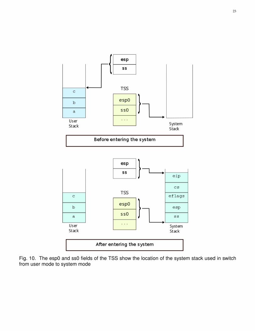
Figure 10 shows how the ss0 and esp0 fields of the TSS are used when switching from usermode to system mode. These fields always point to the bottom of the system stack.
23
Fig. 10. The esp0 and ss0 fields of the TSS show the location of the system stack used in switchfrom user mode to system mode

24
3.5 Zeos system stack
High level operating system routines (typically sys_*) expect the same contents of the systemstack when they start execution. Therefore the Zeos system stack must always be constructed asshown in Figure 11.
@handler Return @ to handler code
HANDLER
EBX First parameter
ECX Second parameter
EDX Third parameter
ESI Fourth parameter
EDI Fifth parameter
EBP Sixth parameter
EAX Result of the syscall
DS Data segment
ES Extra segment
FS File segment
GS Global segment
EIP User space return address
INTERRUPT
CS User space code segment
FLAGS Processor state flags
ESP User space stack pointer
SS User space stack segment
TOP
BOTTOM
Fig. 11. Zeos system stack content at any system service routine after being called by the handler
From bottom to top, the stack begins with the minimal information needed by the processorto return to user mode (white part of the stack in Figure 11). This information is pushed by theprocessor when executes an INT instruction to switch to system privileged level (see Section 3.4)and consists on the address of the top of the user stack (registers SS and ESP), the processor’sstate and the return address to the user mode code (registers CS and EIP).
In top of that, the operating system programmer must decide what information is importantin system mode to be restored when switching back to user mode (grey part of the stack inFigure 11). All this information is pushed in the stack inside the system call handler. In Zeos, thisinformation is composed by the segment registers (GS, FS, ES and DS) , the kernel return value,and the parameters needed by the service routine, pushed from right to left. Finally, since thehandler performs a call to the service routine, the return address to the handler is also pushedin the stack.
It is very important that, to ensure the full compatibility of the operating system routineswith the system calls (see Section 3.8) and fast system calls (see Section 3.9) mechanisms, the OSdependent part of the stack pushed in the handler has to be the same, and needs to be alwaysin the same offset of the stack. If this requirement is not accomplished, the operating system willnot be able to work with syscalls and fast syscalls at the same time.

25
3.6 Programming exceptions
We will program system exceptions in this section. Whenever an exception is produced the normalexecution flow is interrupted and the OS gets the control through the IDT. Table 2 shows theexception positions in the IDT, their names and the number of bytes of their parameters (or errorcode20) if they exist. A real OS tries to recover from the exception and continue the usual execution,but in ZeOS the exception service routines will be very simple: they will show a message in thescreen with the exception that has been generated and they will enter in an infinite loop state(never returning to the user mode and therefore hanging the system).
# IDT Exception Parameter0 Divide error No1 Debug No2 NM1 No3 Breakpoint No4 Overflow No5 Bounds check No6 Invalid opcode No7 Device not available No8 Double fault 4 bytes9 Coprocessor segment overrun No10 Invalid TSS 4 bytes11 Segment not present 4 bytes12 Stack exception 4 bytes13 General protection 4 bytes14 Page fault 4 bytes15 Intel reserved No16 Floating point error No17 Alignment check 4 bytes
TABLE 2List of system exceptions
3.6.1 Writing the service routines
The exception management in this operating system will be very simple. Whenever an exceptionis raised, the OS will show a message with a short description and will wait in an infinite loop,stopping the system.
For example, the code of the general protection service routine is:
void general_protection_routine(){
printk("\nGeneral protection fault\n");while(1);
}
All exception service routines are already implemented inside the libzeos.a library.
20. For some exceptions, the CPU generates a hardware error code and puts it in the system stack before it starts the executionof the exception handler.

26
3.6.2 Exception parameters
As stated in Table 2 some exceptions receive additional information from the hardware in order tobe solved (for instance, information on the type of access that generates the page fault exception).This information has a fixed size (4 bytes) and is pushed into the system stack automatically.Figure 12 shows the system stack contents and the location pointed by the esp and ss registerswhen an exception with an error parameter is raised.
Fig. 12. System stack contents when an exception with an error parameter is raised
3.6.3 Writing the handler
A handler function must be written for each exception. All exception handlers have a commonscheme and must follow these steps (in assembly):
1) Define the function header in assembly. Use the ENTRY macro21 with the name of theexception handler as a parameter (ENTRY(handler_name)) to do it.
• From this point on, the ENTRY macro will always be used in assembly to define afunction header.
2) Save the context in the stack (use the SAVE_ALL macro).3) Call the service routine.4) Restore the context from the stack (use the RESTORE_ALL macro). Notice that the order of
restoring the values of the registers from the stack must match the order in the SAVE_ALLmacro.
5) If needed, clear the error code removing it from the stack. Check Table 2.6) Return from the exception function. Since it is not a "normal" function return because it has
to change mode, an iret rather than a ret22 instruction must be used.
All exception handlers are already implemented inside the libzeos.a library.
3.6.4 Initializing the IDT
Finally, to initialize a position in the IDT, the following function is provided:
21. Check the preprocessor document from the references to know how the macro mechanism works.22. You need to know which data are saved in the stack when going into system mode and what the iret instruction does.

27
setInterruptHandler(int position, void (*handler)(), int privLevel)
The parameters required to write the exception are:
• int position. Entry in the IDT to modify.• void (*handler)(). Address of the handler that will handle the exception23.• int privLevel. Privilege level needed to allow the execution of the handler. In our case,
there are two possibilities: 0 (Kernel) or 3(User), corresponding to the privileged and non-privileged levels respectively.
So, to handle all those exceptions, one call to setInterruptHandler for each exception has beenadded in the file interrupt.c (already implemented in function set_handlers in libzeos.a).
3.7 Programming interrupts
As expected the hardware interrupts works very similar to exceptions. Figure 13 shows the mainsteps for the clock interrupt. This interrupt may arrive at any time and deal with any point in thecode. If the IDT has been correctly programmed, the clock_handler function programmed in theentry.S file will be executed. Inside this function we find a call to the clock_routine function thatwill make the final interrupt management. In the following sections we will show the requiredsteps to program the keyboard interrupt and display the character corresponding to the pressedkey.
Fig. 13. Snapshot of the clock interrupt
3.7.1 The keyboard interrupt management
The keyboard interrupt will display the character that corresponds to the pressed key. Figure 14shows the expected result with a C character displayed in a fixed place on the screen.
To program the keyboard interrupt management, you must:
23. This is a function pointer, you may consult the K&R book "The C Programming language" to refresh your knowledge aboutthem.

28
Fig. 14. Display output after a keyboard interrupt, showing a capital C.
• Write the service routine (keyboard_routine).• Write the handler (keyboard_handler).• Initialize the IDT as it is done for the exceptions. The keyboard interrupt is contained in
entry 33.
setInterruptHandler(33, keyboard_handler, 0);
• Enable the interrupts. The key interrupt is a masked interrupt that is disabled in the providedcode, which means that it is ignored by default. It is necessary to modify the mask thatenables the interrupts, located in the enable_int() routine (file hardware.c).
Notice that just after enabling the interrupts, any of them can be raised. When this occurs, youmust ensure that the system is fully initialized because the interrupt service routines may accessany system structure. For this reason, the best place to enable the interrupts is after all the OSservices have been started and just before performing the return to user mode.
3.7.2 Writing the service routine
After pressing a key, the keyboard service routine will display on the screen the character thatcorresponds to the pressed key.
This service routine performs the following steps:
1) Read the port corresponding to the keyboard data register (0x60) with the routine of the io.cfile:
unsigned char inb(int port)
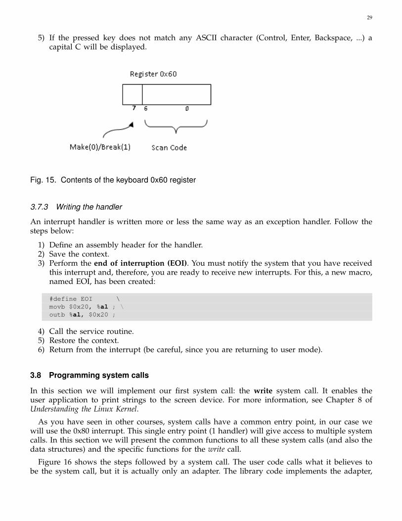
2) Once the value is read from this port, it must distinguish between a make (key pressed)or a break (key released). The contents of this register is shown in Figure 15. Bit number 7specifies whether it is a make or a break. Bits 0..6 contain the scan code to be traslated intoa character.
3) If it is a make, the translation table char_map at interrupt.c must be used to obtain the characterthat matches the scan code.
4) Print the character on the upper left of the screen. For this the printc_xy function in io.c isused.
29
5) If the pressed key does not match any ASCII character (Control, Enter, Backspace, ...) acapital C will be displayed.
Fig. 15. Contents of the keyboard 0x60 register
3.7.3 Writing the handler
An interrupt handler is written more or less the same way as an exception handler. Follow thesteps below:
1) Define an assembly header for the handler.2) Save the context.3) Perform the end of interruption (EOI). You must notify the system that you have received
this interrupt and, therefore, you are ready to receive new interrupts. For this, a new macro,named EOI, has been created:
#define EOI \movb $0x20, %al ; \outb %al, $0x20 ;
4) Call the service routine.5) Restore the context.6) Return from the interrupt (be careful, since you are returning to user mode).
3.8 Programming system calls
In this section we will implement our first system call: the write system call. It enables theuser application to print strings to the screen device. For more information, see Chapter 8 ofUnderstanding the Linux Kernel.
As you have seen in other courses, system calls have a common entry point, in our case wewill use the 0x80 interrupt. This single entry point (1 handler) will give access to multiple systemcalls. In this section we will present the common functions to all these system calls (and also thedata structures) and the specific functions for the write call.
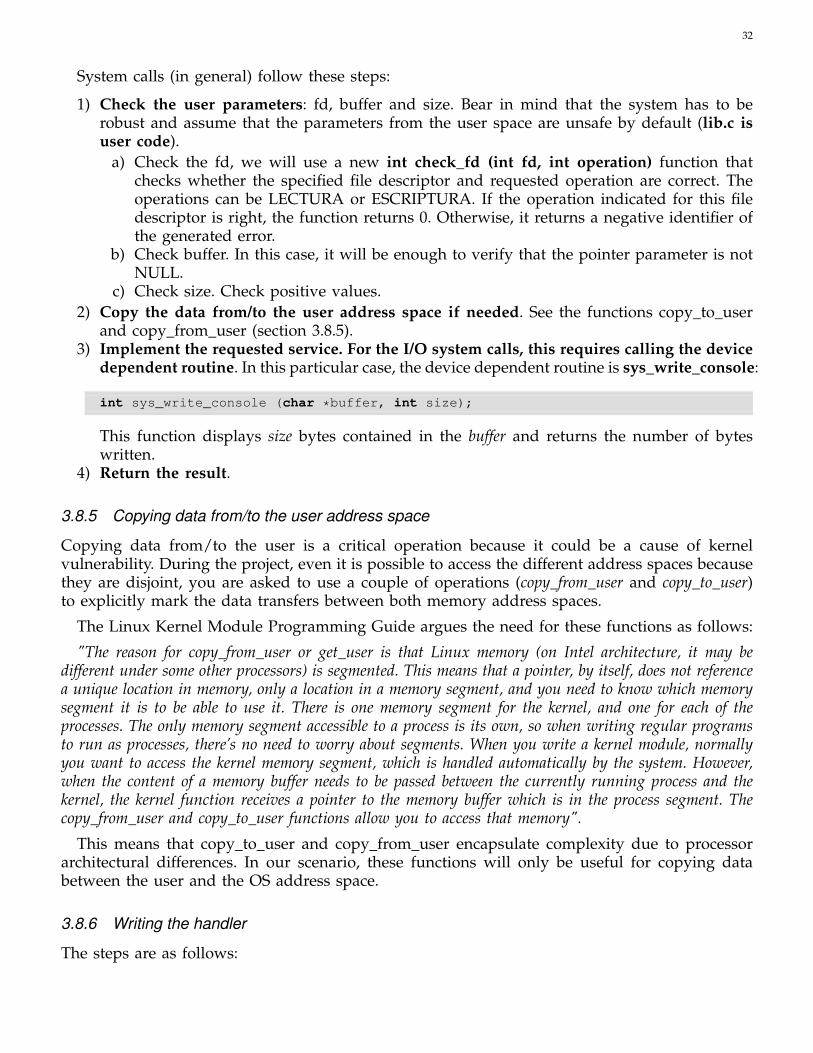
Figure 16 shows the steps followed by a system call. The user code calls what it believes tobe the system call, but it is actually only an adapter. The library code implements the adapter,

30
… write(…);
…
write() { … int $0x80 … }
system_call: … sys_write() …
sys_write() { … if error ret ERROR … }
sys_write_console() { … }
User mode System mode
Fig. 16. Related functions and steps followed by the write system call.
which we will call a wrapper, because it wraps the pass of parameters between user and systemmodes, the generation of the trap (int $0x80) and the processing of the result.
In this case, interrupt 0x80 does not need to be enabled since it is unmasked. However, theIDT must be initialized. Once the interrupt is generated, it is executed as any other interrupt (theexecution of the handler and the execution of the service routine). As explained above, all systemcalls have a common handler, which will be named system_call. In this handler, the systemcall service requested by the user is checked and the corresponding service routine is executed(sys_write in the example).
3.8.1 Independence from devices
As explained in other courses, one of the basic principles of an OS design is independence betweendevices; this is, the interface for input and output system calls is the same regardless of the devicethat is requesting its service.
Keeping this in mind, you will design each call considering a part that is dependent and a partthat is independent from the device. Thus, the system will be prepared to grow in complexity, orto easily add more devices to it. The design will be similar to a real OS.
For example, in this session the sys_write call (independent part) will call sys_write_console(dependent part), in order to print on the screen (but in the future it may call sys_write_printeror sys_write_ext2 or . . . ).
3.8.2 Returning results
The convention in Linux for returning the results of the system calls considers a positive or zeroreturn when the execution of the call is correct and a negative value when an error is detected.In case of error, this negative value specifies the error.
Nevertheless, the returned value of the system call does not reach the user directly, but insteadit is processed by the wrapper of the system call that is found in the library. Thus, if the returnedvalue is positive or zero, it will be returned to the user as is. However, if the value is negative, thewrapper will save the absolute value of the return in an error variable defined in the library (called

31
errno) and return -1 to the user to notify that the system call has an error. If the user requiresfurther information about the error, he/she must consult the errno variable. If the system calldoes not return an error, the errno variable is not modified.
To use this convention in ZeOS, all system calls must return a negative number and specifythe generated error in the event of a wrong execution. The constants used to identify these errorsare contained in the Linux errno.h file. Moreover, your system call wrappers must process thenegative values of the calls, update the errno variable with the absolute value of these errors andreturn -1 to the user.
A function should also be added for the users to obtain information about the error generatedby the previous system call. This function have this interface:
void perror(void);
It will write an error message for the standard output according to the value of the errno variable.
Note: In the description of the system calls that appear in this document, the returned valuesare considered from the point of view of the user, which means that -1 will always be returnedin the case of an error.
3.8.3 Writing the write wrapper
The write wrapper header is:
int write (int fd, char * buffer, int size);
Wrappers must carry out the following steps:
1) Parameter passing: ZeOS implements the parameter passing from user mode to systemmode through the CPU registers, as occurs in Linux. The parameters of the stack must becopied to the registers EBX, ECX, EDX, ESI, EDI. The correct order is the first parameter (onthe left) in EBX, the second parameter in ECX, etc. Note that this order is a hack to exploitthe SAVE_ALL macro and to create the stack structure from section 3.5.
2) Put the identifier of the system call in the EAX register (number 4 for write).3) Generate the trap: int $0x80.4) Process the result (see section 3.8.2).5) Return.
These wrappers must be coded in assembly.
3.8.4 Service Routine to the write system call
In this section we will define the sys_write service routine, which checks that everything workscorrectly and shows the characters on the screen.
int sys_write(int fd, char * buffer, int size);fd: file descriptor. In this delivery it must always be 1.buffer: pointer to the bytes.size: number of bytes.return ’ Negative number in case of error (specifying the kind of error) and
the number of bytes written if OK.
32
System calls (in general) follow these steps:
1) Check the user parameters: fd, buffer and size. Bear in mind that the system has to berobust and assume that the parameters from the user space are unsafe by default (lib.c isuser code).
a) Check the fd, we will use a new int check_fd (int fd, int operation) function thatchecks whether the specified file descriptor and requested operation are correct. Theoperations can be LECTURA or ESCRIPTURA. If the operation indicated for this filedescriptor is right, the function returns 0. Otherwise, it returns a negative identifier ofthe generated error.
b) Check buffer. In this case, it will be enough to verify that the pointer parameter is notNULL.
c) Check size. Check positive values.2) Copy the data from/to the user address space if needed. See the functions copy_to_user
and copy_from_user (section 3.8.5).3) Implement the requested service. For the I/O system calls, this requires calling the device
dependent routine. In this particular case, the device dependent routine is sys_write_console:
int sys_write_console (char *buffer, int size);
This function displays size bytes contained in the buffer and returns the number of byteswritten.
4) Return the result.
3.8.5 Copying data from/to the user address space
Copying data from/to the user is a critical operation because it could be a cause of kernelvulnerability. During the project, even it is possible to access the different address spaces becausethey are disjoint, you are asked to use a couple of operations (copy_from_user and copy_to_user)to explicitly mark the data transfers between both memory address spaces.
The Linux Kernel Module Programming Guide argues the need for these functions as follows:
"The reason for copy_from_user or get_user is that Linux memory (on Intel architecture, it may bedifferent under some other processors) is segmented. This means that a pointer, by itself, does not referencea unique location in memory, only a location in a memory segment, and you need to know which memorysegment it is to be able to use it. There is one memory segment for the kernel, and one for each of theprocesses. The only memory segment accessible to a process is its own, so when writing regular programsto run as processes, there’s no need to worry about segments. When you write a kernel module, normallyyou want to access the kernel memory segment, which is handled automatically by the system. However,when the content of a memory buffer needs to be passed between the currently running process and thekernel, the kernel function receives a pointer to the memory buffer which is in the process segment. Thecopy_from_user and copy_to_user functions allow you to access that memory".
This means that copy_to_user and copy_from_user encapsulate complexity due to processorarchitectural differences. In our scenario, these functions will only be useful for copying databetween the user and the OS address space.
3.8.6 Writing the handler
The steps are as follows:

33
• Save the context.• Check that it is a correct system call number (that the system call identifier belongs to a
defined range of valid system calls). Otherwise, the corresponding error must be returned.• Execute the corresponding system call.• Update the context so that, once restored, the result of the system call can be found in the
EAX register. Remember that C functions store their result in the EAX register24.• Restore the context.• Return to the user mode.
A table is needed to relate the identifier of each call to its routine. The table will be filled inas new system calls are added. This call table, named sys_call_table, will be defined in assemblylike:
ENTRY(sys_call_table).long sys_ni_syscall // sys_ni_syscall address (not implemented).long sys_functionname // sys_functionname address
Each entry contains the memory address of the function to be called. Bear in mind that non-implemented calls in a valid range must implement a call to sys_ni_syscall. This function willjust return a negative identifier for the non-implemented call error. In this case the table definesa single system call with the identifier 1 that will call the sys_functionname (Note that identifier 0will call the not-implemented function).
Thanks to Intel’s memory addressing modes, a single instruction is needed to call a systemfunction from this table indexed by a register (EAX in this case):
call *sys_call_table(, %EAX, 0x04);
So, the syscall table must be extended to enable the write system call. In particular, entries from0 to 3 must be initialized to sys_ni_syscall to return the corresponding error (the syscall doesnot exist). The 5th entry (identifier 4) points to the service routine (that will be implemented insection 3.8.4):
ENTRY (sys_call_table).long sys_ni_syscall // 0.long sys_ni_syscall // 1.long sys_ni_syscall // 2.long sys_ni_syscall // 3.long sys_write // 4
.globl MAX_SYSCALLMAX_SYSCALL = (. - sys_call_table)/4
• Visit https://elixir.bootlin.com/linux/v3.2.102/source/arch/x86/kernel/syscall_table_32.S tolook at the Linux declaration of the sys_call_table table.25
Finally, if the number of the syscall is outside the correct range (from 0 to 4 in this case), thesys_ni_syscall will be called. This function must always return the corresponding error:
24. If the context is not modified, the return value will be the system call identifier.25. Since version 3.3 this table is automatically generated.

34
int sys_ni_syscall(){
return -38; /*ENOSYS*/}
The code for the OS entry point (position 0x80 of the IDT) looks like:
ENTRY(system_call_handler)SAVE_ALL // Save the current contextcmpl $0, %EAX // Is syscall number negative?jl err // If it is, jump to return an errorcmpl $MAX_SYSCALL, %EAX // Is syscall greater than MAX_SYSCALL (4)?jg err // If it is, jump to return an errorcall *sys_call_table(, %EAX, 0x04) // Call the corresponding service routinejmp fin // Finish
err:movl $-ENOSYS, %EAX // Move to EAX the ENOSYS error
fin:movl %EAX, 0x18(%esp) // Change the EAX value in the stackRESTORE_ALL // Restore the contextiret
3.8.7 IDT initialization
Finally, initialize the entry point of a system call using the call:
void setTrapHandler(int posició, void (*handler)(), int nivellPriv)
This function is similar to setInterruptHandler. In this case, since the system calls are invokedfrom the user privilege level, the value for the third parameter will be 3:
setTrapHandler(0x80, system_call_handler, 3);
3.9 Programming fast system calls
Modern processors extend the way of invoking the operating system code with an additionalmechanism to enter the system: fast system calls. The main difference of those calls compared tosoftware interrupts are:
1) The IDT is not accessed. Software interrupts access the IDT to find the operating systementry point address. Fast calls do not use the IDT because the entry point address is storedin one of the specific registers of the processor, called Model Specific Registers(MSRs)26
2) No check of the privilege level is performed. Fast calls can only be executed from userprivilege level. The operating system code does not use them. So, there is no need to checkwhat is the privilege level from which the fast call is performed since it will be alwaysexecuted from user mode.
26. The Model Specific Registers are additional registers of the processor. They can not be used as general purpose registersbecause they have a specific meaning related to the operating system and enable different features of the processor.
35
3) The TSS is not accessed to find the address of the system stack. Instead, this value is readfrom another MSR.
4) Fast calls do not store the processor’s state nor the minimal information to return to usermode in the stack.
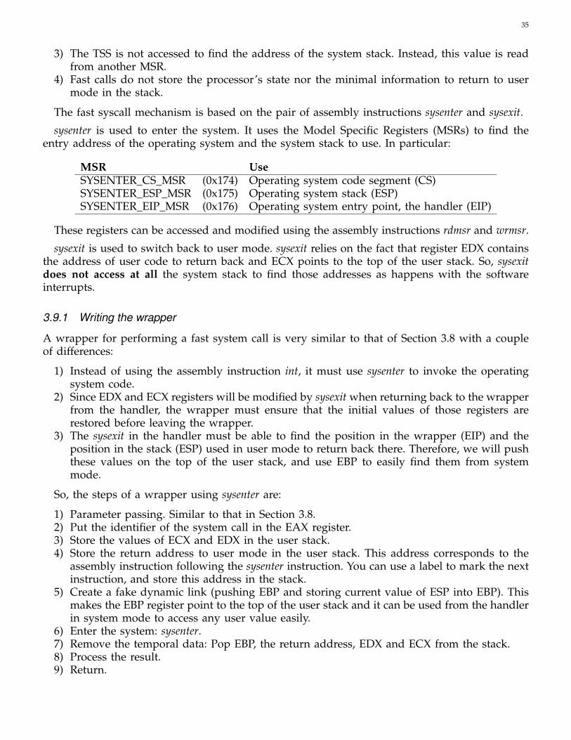
The fast syscall mechanism is based on the pair of assembly instructions sysenter and sysexit.
sysenter is used to enter the system. It uses the Model Specific Registers (MSRs) to find theentry address of the operating system and the system stack to use. In particular:
MSR UseSYSENTER_CS_MSR (0x174) Operating system code segment (CS)SYSENTER_ESP_MSR (0x175) Operating system stack (ESP)SYSENTER_EIP_MSR (0x176) Operating system entry point, the handler (EIP)
These registers can be accessed and modified using the assembly instructions rdmsr and wrmsr.
sysexit is used to switch back to user mode. sysexit relies on the fact that register EDX containsthe address of user code to return back and ECX points to the top of the user stack. So, sysexitdoes not access at all the system stack to find those addresses as happens with the softwareinterrupts.
3.9.1 Writing the wrapper
A wrapper for performing a fast system call is very similar to that of Section 3.8 with a coupleof differences:
1) Instead of using the assembly instruction int, it must use sysenter to invoke the operatingsystem code.
2) Since EDX and ECX registers will be modified by sysexit when returning back to the wrapperfrom the handler, the wrapper must ensure that the initial values of those registers arerestored before leaving the wrapper.
3) The sysexit in the handler must be able to find the position in the wrapper (EIP) and theposition in the stack (ESP) used in user mode to return back there. Therefore, we will pushthese values on the top of the user stack, and use EBP to easily find them from systemmode.
So, the steps of a wrapper using sysenter are:
1) Parameter passing. Similar to that in Section 3.8.2) Put the identifier of the system call in the EAX register.3) Store the values of ECX and EDX in the user stack.4) Store the return address to user mode in the user stack. This address corresponds to the
assembly instruction following the sysenter instruction. You can use a label to mark the nextinstruction, and store this address in the stack.
5) Create a fake dynamic link (pushing EBP and storing current value of ESP into EBP). Thismakes the EBP register point to the top of the user stack and it can be used from the handlerin system mode to access any user value easily.
6) Enter the system: sysenter.7) Remove the temporal data: Pop EBP, the return address, EDX and ECX from the stack.8) Process the result.9) Return.

36
3.9.2 Writing the handler
sysenter does not store the user mode information in the system stack. This makes that a differenthandler for sysenter is needed in the operating system since — as explained in section 3.5 — itmust construct the stack in a specific way to ensure that this stack will be fully compatible withthe service routines. In addition, to switch back to user mode, the handler executes sysexit, settingEDX and ECX to the correct values.
This new handler has the following steps:
1) Save in the stack the same user mode information than the int instruction stores whenswitching to system mode (as explained in section 3.5). In particular, the user return addressand the position from the user mode stack, both accesible through the register EBP.
2) Save the context.3) Check if it is a correct system call number (EAX).4) Execute the corresponding system call (service routine).5) Update the context to store the returned value.6) Restore the context.7) Set EDX with the user return address from the stack.8) Set ECX with the value of the user EBP from the stack.9) Return to user mode: sysexit.
With this procedure, all structures (the syscall table) and code (service routines) will be fullycompatible in both int and sysenter mechanisms.
The handler for sysenter looks like:
ENTRY(syscall_handler_sysenter)push $__USER_DSpush %EBP // User stack addresspushflpush $__USER_CSpush 4(%EBP) // User return addressSAVE_ALLcmpl $0, %EAXjl sysenter_errcmpl $MAX_SYSCALL, %EAXjg sysenter_errcall *sys_call_table(, %EAX, 0x04)jmp sysenter_fin
sysenter_err:movl $-ENOSYS, %EAX
sysenter_fin:movl %EAX, 0x18(%ESP)RESTORE_ALLmovl (%ESP), %EDX // Return addressmovl 12(%ESP), %ECX // User stack addresssti // Enable interrupts againsysexit
3.9.3 Initializing fast system calls
Since sysenter does not use the IDT to find the address of the system call handler but uses theMSRs of the processor, the first thing to do is to enable the sysenter entry point. For this:

37
1) Write an assembly function called writeMSR that accepts two parameters: the number ofthe MSR and the value to store in that MSR. Note: check the syntax of wrmsr to know thetype and the number of parameters of this assembly instruction.
2) Use the previous function, after the IDT initialization, to program the MSR. In particular,MSR 0x174 must be set to KERNEL_CS, 0x175 to INITIAL_ESP and 0x176 to the address ofthe operating system sysenter handler.
3.10 Work to do
3.10.1 Complete Zeos Code
The released code lacks some features explained in the ZEOS document. You have to completeit:
• Implement the macro RESTORE_ALL.• Implement the macro EOI.• Implement the keyboard management.
– Implement the keyboard service routine.– Implement the keyboard handler.– Initialize the IDT with the keyboard handler– Enable the interrupt.
• Implement the write system call.– Implement the sys_write routine.– Modify the sys_call_table with the new routine.– Create a wrapper for the system call.
• Implement the system_call_handler routine.• Initialize either the IDT or the MSRs (or both) with the handler, depending on the mechanism
to invoke the operating system code used (int, sysenter or both).• Implement the errno and perror function.
3.10.2 Clock management
The clock management will display the seconds that have elapsed since the boot process. Figure 17shows the expected result with the time displayed in a fixed place on the screen.
To write the management of an interrupt such as the clock interrupt (that is, a masked type),you must:
• Write the service routine.• Write the handler.• Initialize the entry of the clock interrupt in the IDT. The clock interrupt is contained in entry
32.• Enable the interrupt. The clock interrupt is a masked interrupt that is disabled in the code
provided, which means that it is not dealt with. Modify the mask that enables the interrupts,located in the enable_int() routine (file hardware.c).
Notice that just after enabling the interrupts, one of them can be raised at any time. When thisoccurs, you must ensure that the system is fully initialized because the interrupt service routinesmay access any system structure.

38
Fig. 17. Clock interrupt prints a clock with the minutes and seconds elapsed.
Writing the service routine
Write the corresponding service routine of the clock interrupt. Inside this routine, you must call:zeos_show_clock which will display at the top-right part of the screen a clock with the elapsedtime since the OS booted. Notice that in bochs the clock interrupt is also emulated. So, this showedtime goes faster than the real one.
The header of this function is located at zeos_interrupt.h:
void zeos_show_clock();
Writing the handler
An interrupt handler is written more or less the same way as an exception handler. Follow thesteps below:
1) Define an assembly header for the handler.2) Save the context.3) Perform the EOI (remember that there is a macro for this available). You must notify the
system that you are treating the interrupt.4) Call the service routine.5) Restore the context.6) Return from the interrupt to user mode.
Testing
The seconds that have elapsed since the OS boot process must appear on the screen. If it does notwork, determine the problem with the debugger. Check whether the interrupt is executed andthe handler is executed, the interrupt routine is executed, whether you return to the user mode,etc.

39
3.10.3 Gettime system call
Extend ZeOS to incorporate this new system call. This syscall returns the number of clock tickselapsed since the OS has booted. Its header is:
int gettime();
To implement this system call you will:
1) Create a global variable called zeos_ticks.2) Initialize zeos_ticks to 0 at the beginning of the operating system (main).3) Modify the clock interrupt service routine to increment the zeos_ticks variable.4) Write the wrapper function. The identifier for this system call will be 10.5) Update the system calls table6) Write the service routine.7) Return the result.

40
4 BASIC PROCESS MANAGEMENT
In this section we describe the code and necessary data structures to define and manage processesin ZeOS.
Take into account that the code related to the process management is key to achieve a goodsystem performance. This means that the data structures have to take up minimum space andthat the process management algorithms must be highly efficient.
As you know, a process has its own address space. A running process in user mode accessesits user stack, user data and user code. When running in system mode, it accesses the kernel dataand code and uses its own system stack.
The process management implies knowledge of memory management. Here you will be givensome basic concepts. A lot of work has already been done, but you will have to understand thecode provided to you.
Chapters 3 and 11 of Understanding the Linux Kernel contain information about process man-agement. You can also find useful information about the memory organization in Chapter 2.
This section is the most complex so you are advised to read the following sections carefullyand to understand all the concepts explained.
4.1 Prior concepts
• Process. Data related to the process management: PCB (task_struct), lists, etc.• Process address space. Difference between logical and physical addresses. Paging.• Context switch. Scheduling. Scheduling policies.
4.2 Definition of data structures
One of the goals of this section is to describe the data structures needed to manage processes inZeOS. In particular:
• Process Control Block (PCB) implemented with the task_struct structure in sched.h.• A vector of task_structs to hold the information of several processes.• The system stack integrated with the task_struct of every process.• A free queue to link all the tasks that are available for new processes (to get a quick access
to them).• A ready queue to link all the tasks that are candidate to use the CPU which is already busy.
4.2.1 Process data structures
PCB structure
The PCB should contain all necessary information needed to manage the processes in the system.A basic definition of the task_struct is contained in the sched.h file:
struct task_struct {int PID; /* Process ID */page_table_entry * dir_pages_baseAddr; /* directory base address */
};

41
This structure has initially only two fields: an integer that will serve as the process identifier(PID), and a pointer to the directory pages of the processes (the directory pages points to thepage table of the processes, see section 4.3 for more details). More fields will be added as youadvance in the project.
For easy programming, rather than using two different structures: one for the task_struct andone for the stack for each process, both data structures will be overlapped in memory. To do so,we use the union type of C, which is a special kind of data. In C, if you declare a unionof three fields (a, b and c), the compiler reserves memory for the biggest field instead of thesum of their sizes.
To overlap the task_struct and the system stack, the task_union has been declared. The task_unionshares the memory space between the process descriptor (task_struct) and the system stack ofthe process. Its declaration is:
union task_union {struct task_struct task;unsigned long stack[KERNEL_STACK_SIZE];
};
And you can see the result in Figure 18, where both structures have been depicted sharing thesame memory area, a region of 4096bytes.
Fig. 18. The system stack and task_struct use the same page memory(4k)
The operating system will allow to create and destroy processes, meaning that a bunch of thisstructures will be needed. To store these processes in the system we will use a fixed size array27.The declaration of the task array with the task_union is also provided:
union task_union task[NR_TASKS]
27. A better option would be to create these task_struct structures dinamically, using some kind of dynamic memory allocationbut we do not have this feature yet.
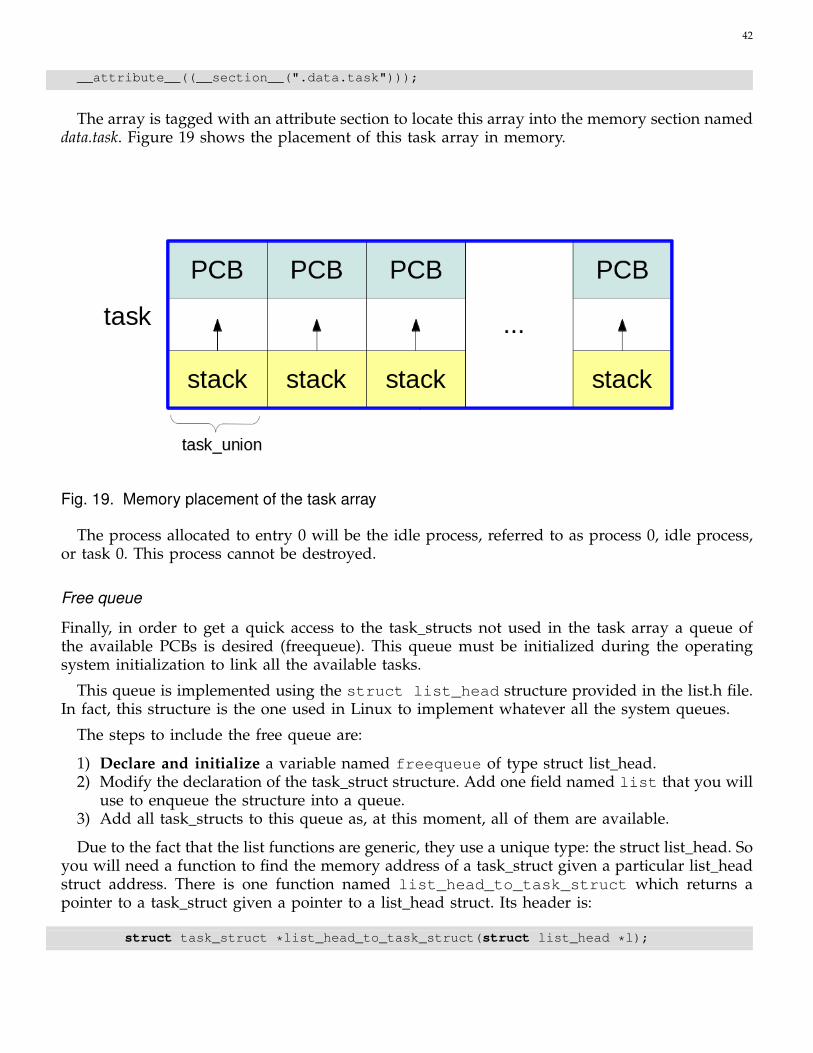
42
__attribute__((__section__(".data.task")));
The array is tagged with an attribute section to locate this array into the memory section nameddata.task. Figure 19 shows the placement of this task array in memory.
Fig. 19. Memory placement of the task array
The process allocated to entry 0 will be the idle process, referred to as process 0, idle process,or task 0. This process cannot be destroyed.
Free queue
Finally, in order to get a quick access to the task_structs not used in the task array a queue ofthe available PCBs is desired (freequeue). This queue must be initialized during the operatingsystem initialization to link all the available tasks.
This queue is implemented using the struct list_head structure provided in the list.h file.In fact, this structure is the one used in Linux to implement whatever all the system queues.
The steps to include the free queue are:
1) Declare and initialize a variable named freequeue of type struct list_head.2) Modify the declaration of the task_struct structure. Add one field named list that you will
use to enqueue the structure into a queue.3) Add all task_structs to this queue as, at this moment, all of them are available.
Due to the fact that the list functions are generic, they use a unique type: the struct list_head. Soyou will need a function to find the memory address of a task_struct given a particular list_headstruct address. There is one function named list_head_to_task_struct which returns apointer to a task_struct given a pointer to a list_head struct. Its header is:
struct task_struct *list_head_to_task_struct(struct list_head *l);
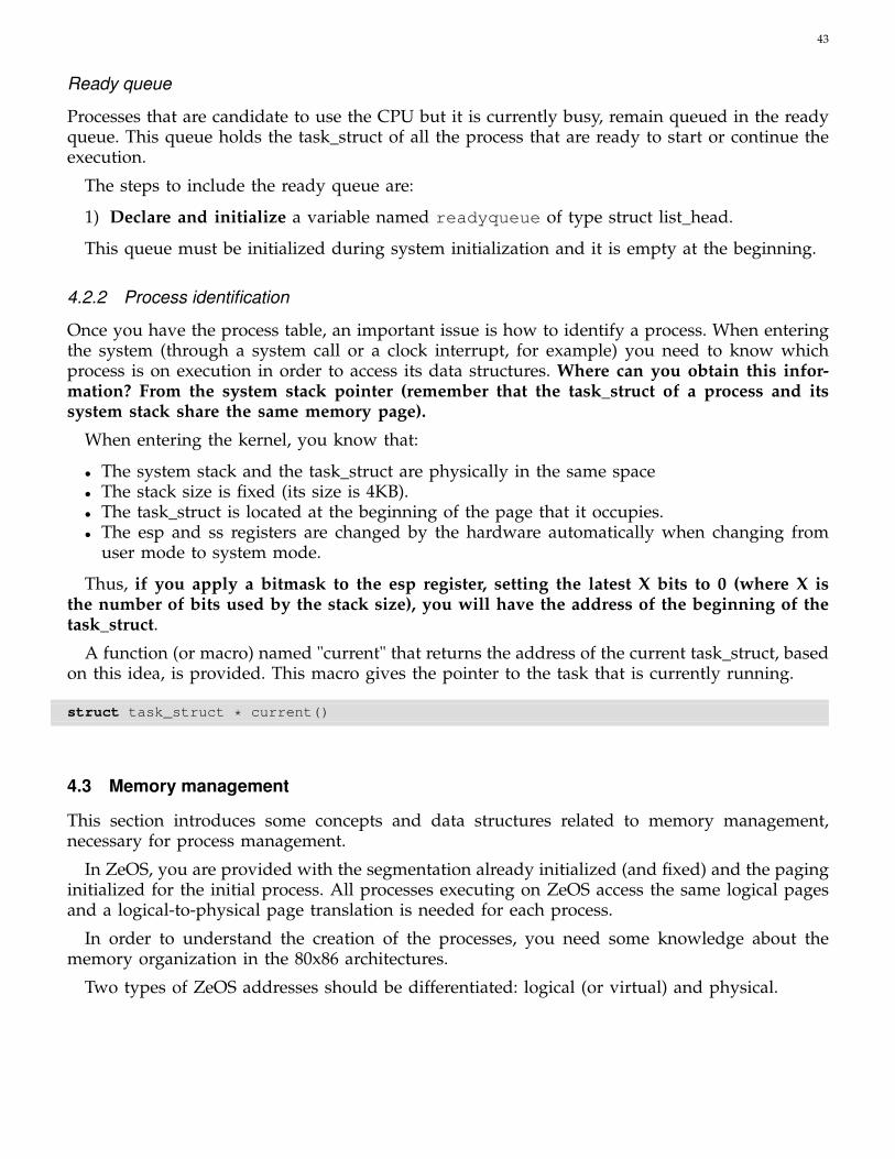
43
Ready queue
Processes that are candidate to use the CPU but it is currently busy, remain queued in the readyqueue. This queue holds the task_struct of all the process that are ready to start or continue theexecution.
The steps to include the ready queue are:
1) Declare and initialize a variable named readyqueue of type struct list_head.
This queue must be initialized during system initialization and it is empty at the beginning.
4.2.2 Process identification
Once you have the process table, an important issue is how to identify a process. When enteringthe system (through a system call or a clock interrupt, for example) you need to know whichprocess is on execution in order to access its data structures. Where can you obtain this infor-mation? From the system stack pointer (remember that the task_struct of a process and itssystem stack share the same memory page).
When entering the kernel, you know that:
• The system stack and the task_struct are physically in the same space• The stack size is fixed (its size is 4KB).• The task_struct is located at the beginning of the page that it occupies.• The esp and ss registers are changed by the hardware automatically when changing from
user mode to system mode.
Thus, if you apply a bitmask to the esp register, setting the latest X bits to 0 (where X isthe number of bits used by the stack size), you will have the address of the beginning of thetask_struct.
A function (or macro) named "current" that returns the address of the current task_struct, basedon this idea, is provided. This macro gives the pointer to the task that is currently running.
struct task_struct * current()
4.3 Memory management
This section introduces some concepts and data structures related to memory management,necessary for process management.
In ZeOS, you are provided with the segmentation already initialized (and fixed) and the paginginitialized for the initial process. All processes executing on ZeOS access the same logical pagesand a logical-to-physical page translation is needed for each process.
In order to understand the creation of the processes, you need some knowledge about thememory organization in the 80x86 architectures.
Two types of ZeOS addresses should be differentiated: logical (or virtual) and physical.

44
• Logical address28. A 32-bit unsigned integer that represents up to 4GB of memory. The addressrange is from 0x00000000 to 0xffffffff. All the addresses generated by the cpu are logicaladdresses and translated to physical addresses by the MMU.
• Physical address. They are represented by 32-bit unsigned integers. Used to address memoryfrom the chip.
Fig. 20. Translation from logical addresses to physical addresses
Figure 20 shows the relationship between the different addresses. A brief description of seg-mentation and paging concepts will now be given.
4.3.1 MMU: Paging mechanism
Paging translates logical addresses into physical addresses. The memory is arranged in pageframes of equal size. The data structure that translates linear addresses into physical addressesis the page table.
To activate the paging mechanism in the 80x86 architectures, it is necessary to activate thePG bit of the cr0 register. PG=0 means that the linear addresses are the same as the physicaladdresses. This initialization is already done in the code provided in ZeOS.
4.3.2 The directory and page table
The addressing mode in ZeOS has to use the two indexing levels offered by the 80x86 pagingarchitecture: page directory and page table. Each page directory contains the base addresses of thepage tables defined in the system for one process. The page tables contain the actual translations
28. A difference is established between logical and linear in "Understanding the Linux Kernel". What we refer to as "logical"here is called "linear" in the book.
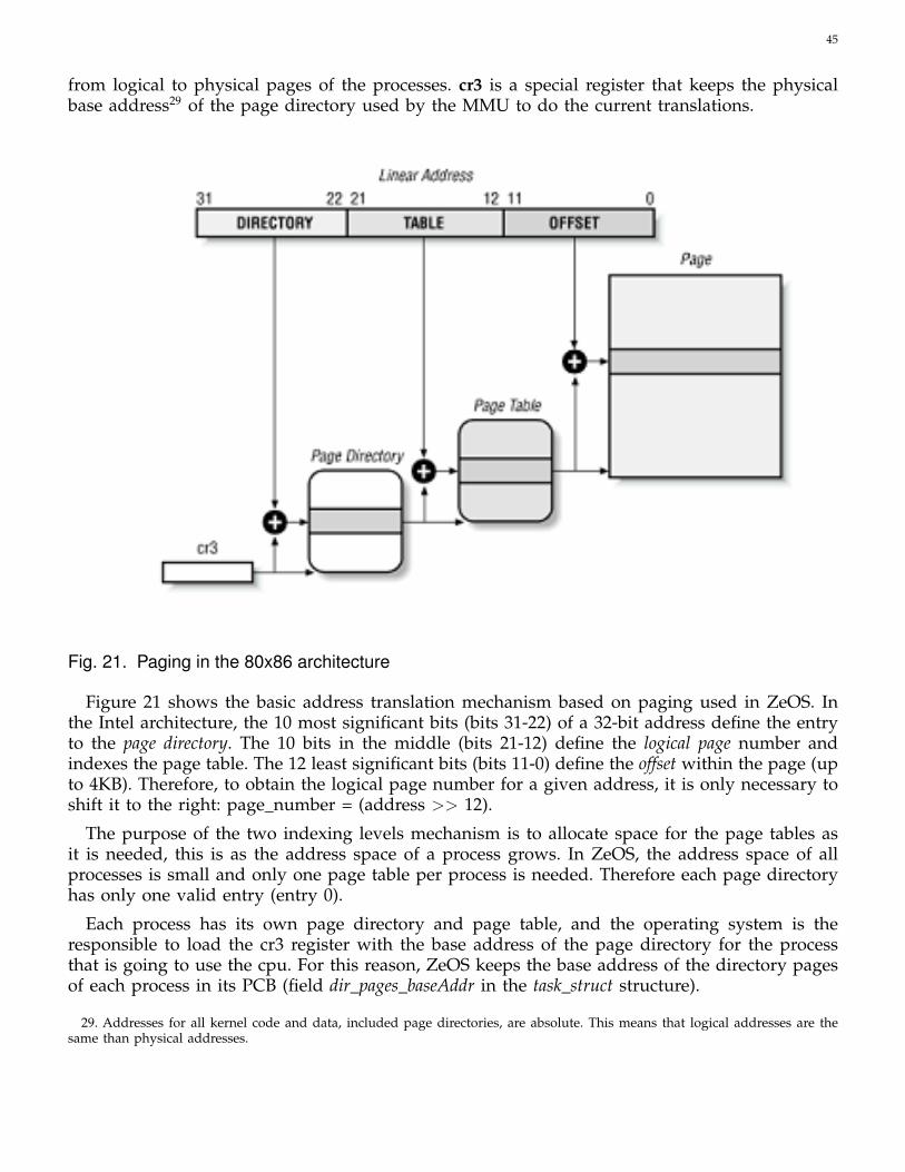
45
from logical to physical pages of the processes. cr3 is a special register that keeps the physicalbase address29 of the page directory used by the MMU to do the current translations.
Fig. 21. Paging in the 80x86 architecture
Figure 21 shows the basic address translation mechanism based on paging used in ZeOS. Inthe Intel architecture, the 10 most significant bits (bits 31-22) of a 32-bit address define the entryto the page directory. The 10 bits in the middle (bits 21-12) define the logical page number andindexes the page table. The 12 least significant bits (bits 11-0) define the offset within the page (upto 4KB). Therefore, to obtain the logical page number for a given address, it is only necessary toshift it to the right: page_number = (address >> 12).
The purpose of the two indexing levels mechanism is to allocate space for the page tables asit is needed, this is as the address space of a process grows. In ZeOS, the address space of allprocesses is small and only one page table per process is needed. Therefore each page directoryhas only one valid entry (entry 0).
Each process has its own page directory and page table, and the operating system is theresponsible to load the cr3 register with the base address of the page directory for the processthat is going to use the cpu. For this reason, ZeOS keeps the base address of the directory pagesof each process in its PCB (field dir_pages_baseAddr in the task_struct structure).
29. Addresses for all kernel code and data, included page directories, are absolute. This means that logical addresses are thesame than physical addresses.
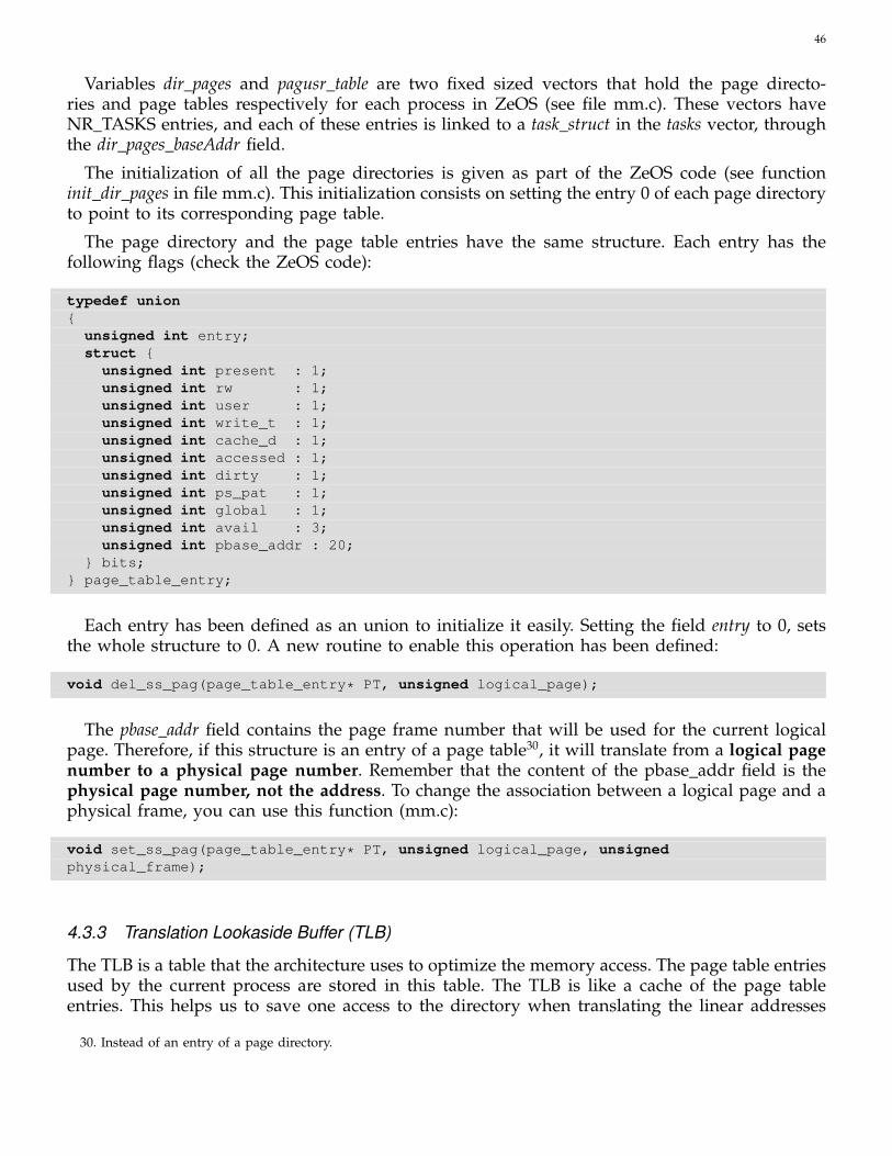
46
Variables dir_pages and pagusr_table are two fixed sized vectors that hold the page directo-ries and page tables respectively for each process in ZeOS (see file mm.c). These vectors haveNR_TASKS entries, and each of these entries is linked to a task_struct in the tasks vector, throughthe dir_pages_baseAddr field.
The initialization of all the page directories is given as part of the ZeOS code (see functioninit_dir_pages in file mm.c). This initialization consists on setting the entry 0 of each page directoryto point to its corresponding page table.
The page directory and the page table entries have the same structure. Each entry has thefollowing flags (check the ZeOS code):
typedef union{
unsigned int entry;struct {
unsigned int present : 1;unsigned int rw : 1;unsigned int user : 1;unsigned int write_t : 1;unsigned int cache_d : 1;unsigned int accessed : 1;unsigned int dirty : 1;unsigned int ps_pat : 1;unsigned int global : 1;unsigned int avail : 3;unsigned int pbase_addr : 20;
} bits;} page_table_entry;
Each entry has been defined as an union to initialize it easily. Setting the field entry to 0, setsthe whole structure to 0. A new routine to enable this operation has been defined:
void del_ss_pag(page_table_entry* PT, unsigned logical_page);
The pbase_addr field contains the page frame number that will be used for the current logicalpage. Therefore, if this structure is an entry of a page table30, it will translate from a logical pagenumber to a physical page number. Remember that the content of the pbase_addr field is thephysical page number, not the address. To change the association between a logical page and aphysical frame, you can use this function (mm.c):
void set_ss_pag(page_table_entry* PT, unsigned logical_page, unsignedphysical_frame);
4.3.3 Translation Lookaside Buffer (TLB)
The TLB is a table that the architecture uses to optimize the memory access. The page table entriesused by the current process are stored in this table. The TLB is like a cache of the page tableentries. This helps us to save one access to the directory when translating the linear addresses
30. Instead of an entry of a page directory.
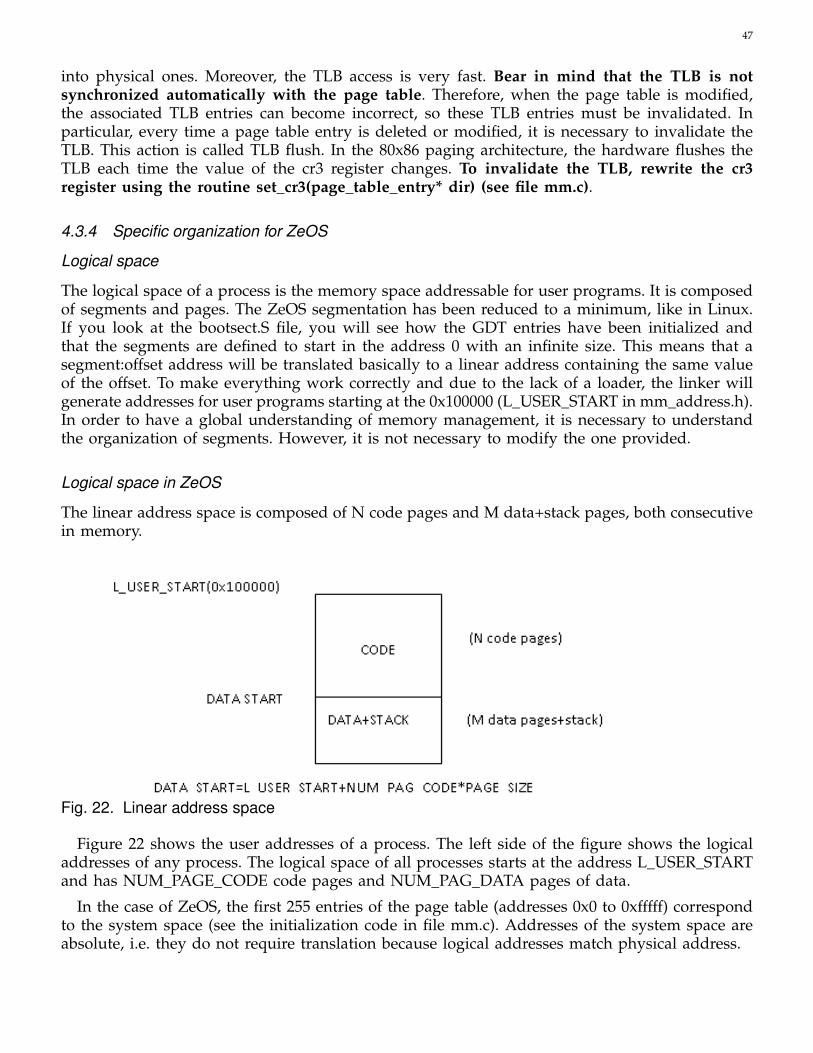
47
into physical ones. Moreover, the TLB access is very fast. Bear in mind that the TLB is notsynchronized automatically with the page table. Therefore, when the page table is modified,the associated TLB entries can become incorrect, so these TLB entries must be invalidated. Inparticular, every time a page table entry is deleted or modified, it is necessary to invalidate theTLB. This action is called TLB flush. In the 80x86 paging architecture, the hardware flushes theTLB each time the value of the cr3 register changes. To invalidate the TLB, rewrite the cr3register using the routine set_cr3(page_table_entry* dir) (see file mm.c).
4.3.4 Specific organization for ZeOS
Logical space
The logical space of a process is the memory space addressable for user programs. It is composedof segments and pages. The ZeOS segmentation has been reduced to a minimum, like in Linux.If you look at the bootsect.S file, you will see how the GDT entries have been initialized andthat the segments are defined to start in the address 0 with an infinite size. This means that asegment:offset address will be translated basically to a linear address containing the same valueof the offset. To make everything work correctly and due to the lack of a loader, the linker willgenerate addresses for user programs starting at the 0x100000 (L_USER_START in mm_address.h).In order to have a global understanding of memory management, it is necessary to understandthe organization of segments. However, it is not necessary to modify the one provided.
Logical space in ZeOS
The linear address space is composed of N code pages and M data+stack pages, both consecutivein memory.
Fig. 22. Linear address space
Figure 22 shows the user addresses of a process. The left side of the figure shows the logicaladdresses of any process. The logical space of all processes starts at the address L_USER_STARTand has NUM_PAGE_CODE code pages and NUM_PAG_DATA pages of data.
In the case of ZeOS, the first 255 entries of the page table (addresses 0x0 to 0xfffff) correspondto the system space (see the initialization code in file mm.c). Addresses of the system space areabsolute, i.e. they do not require translation because logical addresses match physical address.

48
Each entry represents 4KB (it is the page size). L_USER_START»12 is the first logical page of theuser code (you must define a constant to access this page in the file mm_address.h). Therefore, theentire process has 255+NUM_PAGE_CODE+NUM_PAGE_DATA valid entries in the page table:0-255 for the system, only accessible when in kernel mode, NUM_PAG_CODE pages for the usercode and NUM_PAG_DATA pages for the data and user stack. In the initial ZeOS configuration,NUM_PAG_CODE=8 and NUM_PAG_DATA=20 (see file mm_address.h).
Both logical and physical pages for system and user code are shared. This means that the logicalentries in the page table of all processes point to the same physical pages.
The pages for user data+stack are private and therefore the translation from logical addressesto physical addresses (or frame) will be different for each process.
For each new process, it is necessary to initialize its whole page table with the suitable trans-lation for each logical page.
As few pages will be used, a single entry of each page directory will be used (ENTRY_DIR_PAGES).This entry has the address of the corresponding page table. And register cr3 points to the baseaddress of the current page directory.
For each context switch it is necessary to change the value of the cr3 register to point to theprocess that it is going to use the cpu.
Remember that the hardware uses the information in the page table to translate all the accessesto memory: it checks that the type of access is enable for the target logical address and translatethe address to complete the access. If the hardware is not able to complete the access it generatesan exception.
In order to avoid page faults inside the operating system, ZeOS has to check that all theaddresses passed by the user as parameters are valid. For this purpose, a function named access_okhas been provided. This function, given a user memory address, a block size and a type of access,checks in the page table of the process if the access is valid.
int access_ok(int type, const void *addr, unsigned long size)type READ or WRITEaddr user addresssize block size to checkreturns 1 if correct and 0 otherwise
Physical space
As mentioned above, the logical space is consecutive but the physical space is not. The physicalmemory will be organized as follows: the code pages will be shared by all the processes and theywill start at PH_USER_START (defined in segment.h). Starting at this address, the system willplace memory pages for user data and user stacks of created processes (see Figure 23).
Notice that the only difference between the various processes will be the entries of the pagetable corresponding to the user data and user stack.
The physical pages or frames are computed from physical addresses. For example, the physicalpages for the code of process P0 will start at the frame PH_USER_START»12. A macro namePH_PAGE to compute the page number starting from a memory address has been provided:
#define PH_PAGE(x) (x>>12)
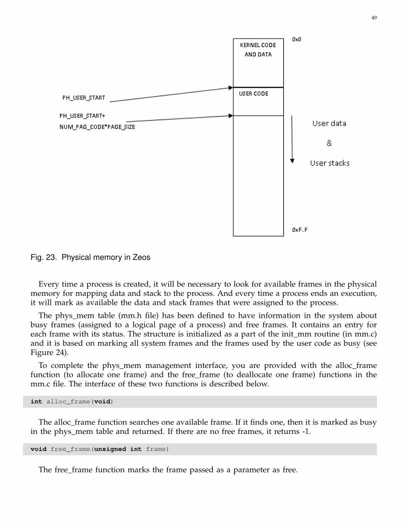
49
Fig. 23. Physical memory in Zeos
Every time a process is created, it will be necessary to look for available frames in the physicalmemory for mapping data and stack to the process. And every time a process ends an execution,it will mark as available the data and stack frames that were assigned to the process.
The phys_mem table (mm.h file) has been defined to have information in the system aboutbusy frames (assigned to a logical page of a process) and free frames. It contains an entry foreach frame with its status. The structure is initialized as a part of the init_mm routine (in mm.c)and it is based on marking all system frames and the frames used by the user code as busy (seeFigure 24).
To complete the phys_mem management interface, you are provided with the alloc_framefunction (to allocate one frame) and the free_frame (to deallocate one frame) functions in themm.c file. The interface of these two functions is described below.
int alloc_frame(void)
The alloc_frame function searches one available frame. If it finds one, then it is marked as busyin the phys_mem table and returned. If there are no free frames, it returns -1.
void free_frame(unsigned int frame)
The free_frame function marks the frame passed as a parameter as free.
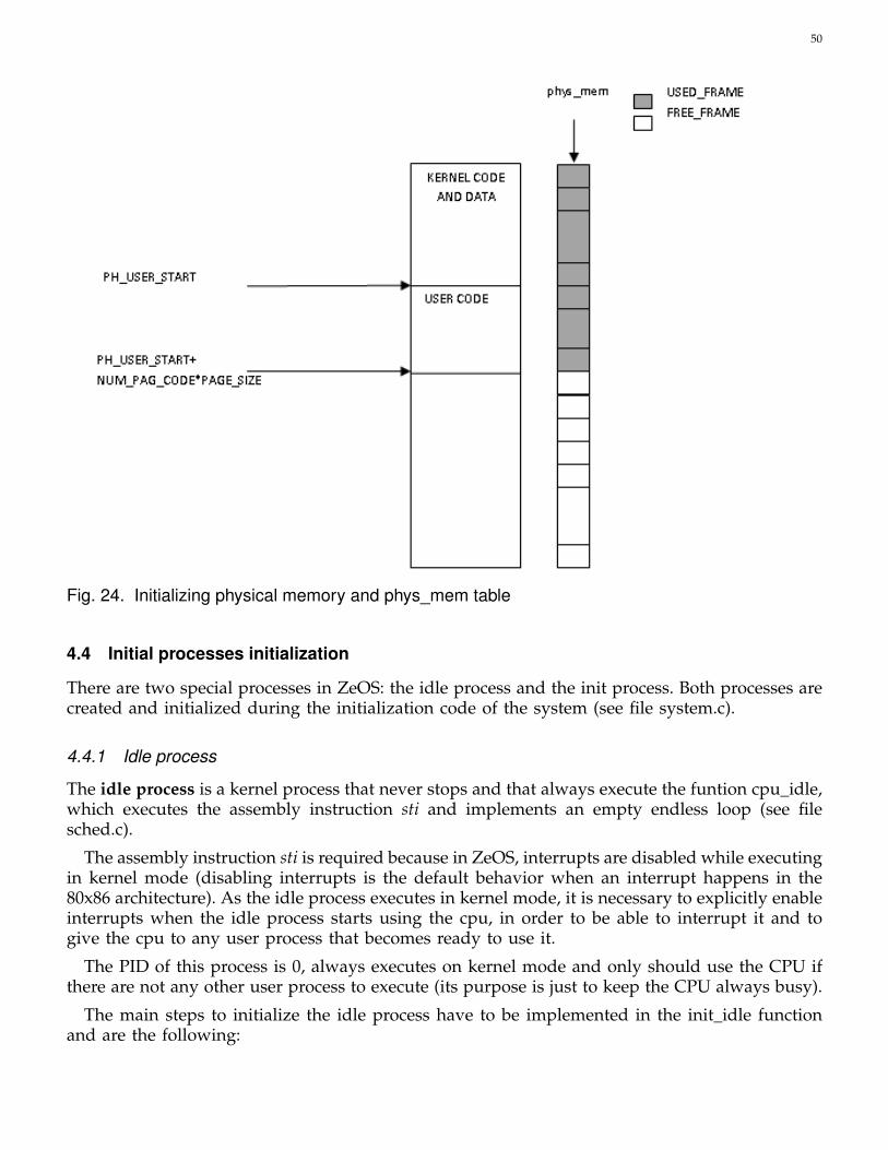
50
Fig. 24. Initializing physical memory and phys_mem table
4.4 Initial processes initialization
There are two special processes in ZeOS: the idle process and the init process. Both processes arecreated and initialized during the initialization code of the system (see file system.c).
4.4.1 Idle process
The idle process is a kernel process that never stops and that always execute the funtion cpu_idle,which executes the assembly instruction sti and implements an empty endless loop (see filesched.c).
The assembly instruction sti is required because in ZeOS, interrupts are disabled while executingin kernel mode (disabling interrupts is the default behavior when an interrupt happens in the80x86 architecture). As the idle process executes in kernel mode, it is necessary to explicitly enableinterrupts when the idle process starts using the cpu, in order to be able to interrupt it and togive the cpu to any user process that becomes ready to use it.
The PID of this process is 0, always executes on kernel mode and only should use the CPU ifthere are not any other user process to execute (its purpose is just to keep the CPU always busy).
The main steps to initialize the idle process have to be implemented in the init_idle functionand are the following:
51
1) Get an available task_union from the freequeue to contain the characteristics of this process2) Assign PID 0 to the process.3) Initialize field dir_pages_baseAaddr with a new directory to store the process address space
using the allocate_DIR routine.4) Initialize an execution context for the procees to restore it when it gets assigned the cpu
(see section 4.5) and executes cpu_idle.5) Define a global variable idle_task
struct task_struct * idle_task;
6) Initialize the global variable idle_task, which will help to get easily the task_struct of theidle process.
The first time that the idle process will use the cpu will be due to a cpu scheduling decision,when there are not more candidates to use the cpu. Thus, the context switch routine will be incharge of putting this process on execution. This means that we need to initialize the context ofthe idle process as the context switch routine requires to restore the context of any process. Thiscontext switch routine restores the execution of any process in the same state that it had beforeinvoking it (see subsection 4.5 for more details). This is achieved by undoing the dynamic link inthe stack and then return using the code address in top of the stack (see figure 25). This meansthat we need to:
1) Store in the stack of the idle process the address of the code that it will execute (addressof the cpu_idle function).
2) Store in the stack the initial value that we want to assign to register ebp when undoingthe dynamic link (it can be 0),
3) Finally, we need to keep (in a field of its task_struct) the position of the stack wherewe have stored the initial value for the ebp register. This value will be loaded in the espregister when undoing the dynamic link.
Notice that as part of this initialization it is not necessary to modify the page table of thisprocess. The reason is that this process is a kernel process and only needs to use those pagesthat contain kernel code and kernel data which are already initialized during the general memoryinitialization in the init_mm function (see file mm.c). This function allocates all the physical pagesrequired for the kernel pages (both code and data pages) and initializes all the page tables in thesystem with the translation for these kernel pages, which are common for all the processes (seefunctions init_frames and init_table_pages in file mm.c).
4.4.2 Init process
The init process is the first user process to be executed after booting the OS. Its PID is 1 and itexecutes the user code. Since the init process is the first one executed, it becomes the parent forthe rest of processes in the system. The code for this process is implemented in the user.c file.
The steps to initialize the init process have to be implemented in the init_task1 function whichis called from the function main in system.c. Those steps are:
1) Assign PID 1 to the process2) Initialize field dir_pages_baseAaddr with a new directory to store the process address space
using the allocate_DIR routine.

52
Fig. 25. Idle process: putting it on execution
3) Complete the initialization of its address space, by using the function set_user_pages (see filemm.c). This function allocates physical pages to hold the user address space (both code anddata pages) and adds to the page table the logical-to-physical translation for these pages.Remind that the region that supports the kernel address space is already configure for allthe possible processes by the function init_mm.
4) Update the TSS to make it point to the new_task system stack. In case you use sysenter youmust modify also the MSR number 0x175.
5) Set its page directory as the current page directory in the system, by using the set_cr3function (see file mm.c).
This process is the first process that will use the cpu after the system initialization. This meansthat the context switch routine is not involved with the first execution of this process. It is thefunction return_gate which prepares the stack of the process to enable the execution of the usercode (see file hardware.c). At the end of return_gate, the lret assembly instruction is executed todowngrade the privilege level to user level and to execute the main function in the user.c file.
4.4.3 Zeos implementation details
As part of the initialization code it is necessary to initialize both processes: the idle and the init. Infile sched.c you have defined two empty functions for this purpose: init_idle and init_task1. Thesefunctions are invoked from the system main function (see file system.c), and you have to completethem with the necessary steps to initialize both processes. In addition, you have to delete thesentence that invoke the function monoprocess_init_addr_space. This function initializes theaddress space of the monoprocess version of ZeOS and it is not needed for the multitaskingversion that you are building now.

53
4.5 Process switch
Zeos provides a routine for making the context switch between two processes. This context switchis performed in kernel mode.
The context switch consists of exchanging the process that is being executed with anotherprocess. It changes the user address space (changing the page table), changes the kernel stack(to restore the new context), and restores the new hardware context. This routine will be namedtask_switch.
Its header is:
void task_switch(union task_union *new)new: pointer to the task_union of the process that will be executed
This routine 1) saves the registers ESI, EDI and EBX31, 2) calls the inner_task_switch routine, and3) restores the previously saved registers.
The inner_task_switch routine has the same header as the previous task_switch, and it restoresthe execution of the new process in the same state that it had before invoking this routine. Thisis achieved by changing to the new kernel stack, undoing the dynamic link in the stack (usuallycreated by the C compiler when a function is called) and then continue the execution at the codeaddress in the top of the stack. Figure 26 shows the stages of the stack of the current processduring the invocation of the context switch. The last picture is the expected state of any processstack to be restored.
Fig. 26. Stack stages during the context switch invocation
The following steps are needed to perform a context switch:
31. Usually the compiler is smart enough to detect that these registers are modified inside the function code and it saves themautomatically, but, in this case, the compiler is not aware of the whole code of the function (due to the trickeries that you will seesoon) and potentially these registers may be modified, meaning that these registers would have a different value when returningfrom this function. The easy solution is to save and restore them manually.

54
1) Update the pointer to the system stack to point to the stack of new_task. This step dependson the implemented mechanism to enter the system. In the case that the int assemblyinstruction is used to invoke the system code, TSS.esp0 must be modified to make it pointto the stack of new_task. If the system code is invoked using sysenter, MSR number 0x175must be also modified.
2) Change the user address space by updating the current page directory: use the set_cr3funtion to set the cr3 register to point to the page directory of the new_task.
3) Store the current value of the EBP register in the PCB. EBP has the address of the currentsystem stack where the inner_task_switch routine begins (the dynamic link).
4) Change the current system stack by setting ESP register to point to the stored value in thenew PCB.
5) Restore the EBP register from the stack.6) Return to the routine that called this one using the instruction RET (usually task_switch,
but. . . ).
The context switch is used when the scheduling policy decides that a new process must beexecuted, or when a process blocks.
4.5.1 Initial testing
You may use the idle and init processes to check that it works (for example, executing the initprocess at the beginning and after some ticks (or after a keypress) make a task_switch to the idle).
4.6 Process creation and identification
In this part, two system calls related to process management will be described in ZeOS: getpidand fork. getpid returns the pid of the process that calls it. fork creates a new process, a copy ofthe one that calls it (referred to as parent), inserts it into the processes list, ready to execute, andreturns its pid.
4.6.1 getpid system call implementation
The header of the call is:
int getpid(void)
It must return the pid of the process that called it. The identification of the getpid call is 20.
Since this is a very simple system call, its implementation is straightforward.
The wrapper routine moves to eax the identifier of the getpid syscall (20), traps the kernel andreturns the correspoding PID also in the eax register. The service routine returns the PID in thetask_struct of the current process.
4.6.2 fork system call implementation
The header of the call is:
int fork(void)

55
It returns a different value depending on whether it is the parent or the child. If it is the parent,it returns the pid of the created process; if it is the child, it returns a 0. If an error occurs it returnsa -1.
Regarding the memory initialization, it is necessary to allocate free physical pages to hold theuser data+stack region of the child process: system data and code are shared by all processesand since user code is read-only it is not necessary to replicate it. The data+stack region isinherited from the parent and is private thereafter. This means that the new allocated pageswill be initializated as a copy of the data+stack region of the parent.
The implementation of the fork system calls carries out the following steps:
1) Implement the wrapper of the system call. The identifier of the system call is 2.2) Implement the sys_fork service routine. It must:
a) Get a free task_struct for the process. If there is no space for a new process, an errorwill be returned.
b) Inherit system data: copy the parent’s task_union to the child. Determine whether it isnecessary to modify the page table of the parent to access the child’s system data. Thecopy_data function can be used to copy.
c) Initialize field dir_pages_baseAddr with a new directory to store the process addressspace using the allocate_DIR routine.
d) Search physical pages in which to map logical pages for data+stack of the child process(using the alloc_frames function). If there is no enough free pages, an error will bereturn.
e) Inherit user data:i) Create new address space: Access page table of the child process through the direc-
tory field in the task_struct to initialize it (get_PT routine can be used):A) Page table entries for the system code and data and for the user code can be a
copy of the page table entries of the parent process (they will be shared)B) Page table entries for the user data+stack have to point to new allocated pages
which hold this regionii) Copy the user data+stack pages from the parent process to the child process. The
child’s physical pages cannot be directly accessed because they are not mapped inthe parent’s page table. In addition, they cannot be mapped directly because thelogical parent process pages are the same. They must therefore be mapped in newentries of the page table temporally (only for the copy). Thus, both pages can beaccessed simultaneously as follows:
A) Use temporal free entries on the page table of the parent. Use the set_ss_pag anddel_ss_pag functions.
B) Copy data+stack pages.C) Free temporal entries in the page table and flush the TLB to really disable the
parent process to access the child pages.f) Assign a new PID to the process. The PID must be different from its position in the
task_array table.g) Initialize the fields of the task_struct that are not common to the child.
i) Think about the register or registers that will not be common in the returning of thechild process and modify its content in the system stack so that each one receive itsvalues when the context is restored.

56
h) Prepare the child stack with a content that emulates the result of a call to task_switch.This process will be executed at some point by issuing a call to task_switch. Thereforethe child stack must have the same content as the task_switch expects to find, so it willbe able to restore its context in a known position. The stack of this new process mustbe forged so it can be restored at some point in the future by a task_switch. In fact thisnew process has to a) restore its hardware context and b) continue the execution of theuser process, so you must create a routine ret_from_fork which does exactly this. Anduse it as the restore point like in the idle process initialization 4.4.
i) Insert the new process into the ready list: readyqueue. This list will contain all processesthat are ready to execute but there is no processor to run them.
j) Return the pid of the child process.
4.7 Process scheduling
In order to execute the different processes queued in the ready queue, a policy must be definedto select the next process. In this section, you will add a process scheduler that uses a roundrobin policy. However, the code of this scheduler must be generic enough to replace the roundrobin policy with a different one. For this reason we define an interface for the main schedulingfunctions.
4.7.1 Main scheduling functions
Following we describe the interface that you have to implement to provide ZeOS with a schedul-ing policy.
• Function to update the relevant information to take scheduling decisions. In the case of theround robin policy it should update the number of ticks that the process has executed sinceit got assigned the cpu.
void update_sched_data_rr (void)
• Function to decide if it is necessary to change the current process.
int needs_sched_rr (void)returns: 1 if it is necessary to change the current process and 0otherwise
• Function to update the current state of a process to a new state. This function deletes theprocess from its current queue (state) and inserts it into a new queue (for example, the freequeue or the ready queue). If the current state of the process is running, then there is no needto delete it from any queue. The parameters of this function are the task_struct of the processand the queue according to the new state of the process. If the new state of the process isrunning, then the queue parameter should be NULL.
void update_process_state_rr (struct task_struct *t, struct list_head *dst_queue)
• Function to select the next process to execute, to extract it from the ready queue and to invokethe context switch process. This function should always be executed after updating the stateof the current process (after calling function update_process_state_rr).

57
void sched_next_rr (void)
You have to:
1) Add the necessary fields to the task_struct to implement the scheduler.2) Create a Round Robin scheduling policy. To do this, you should implement the previous
interface and you should add the code necessary to invoke those functions.
4.7.2 Round robin policy implementation
The round robin policy consists in executing each process during a specific number of ticks (itsquantum), doing a task_switch when the quantum finishes. This quantum can be different for eachprocess and each process inherits it from its parent. Ticks are updated in the clock interrupt; thescheduling policy will then be invoked there to check if a new process must be executed.
Adding this policy requires implementing a new function, named schedule, and calling it when-ever a scheduling decission is needed. The steps that this function has to perform are:
• Control how many tics the current process has spent on the CPU. Use a global variable thatis decreased with every tic.
• Decide if a context switch is required. A context switch is required when the quantum is overand there are some candidate process to use the CPU. Recall that the idle process should usethe CPU ONLY if there are not any other user process that can advance with the execution.
• If a context switch is required:– Update the readyqueue, if current process is not the idle process, by inserting the current
process at the end of the readyqueue.– Extract the first process of the readyqueue, which will become the current process;– And perform a context switch to this selected process. Remember that when a process
returns to the execution stage after a context switch, its quantum ticks must be restored.
Additionally, to complete the implementation it is necessary to add a function named get_quantumthat returns the quantum of the task passed as a parameter and a function set_quantum thatmodifies the quantum of the process.
int get_quantum (struct task_struct *t);void set_quantum (struct task_struct *t, int new_quantum):
Finally, check that the round robin policy works correctly by showing the pid of the runningprocess.
4.8 Process destruction
This section describes the steps to destroy a process. This destruction is implemented in the exitsystem call, which destroys the process that calls it. Therefore, it must delete the process fromthe processes table and make a context switch.
Its header is:
void exit(void)
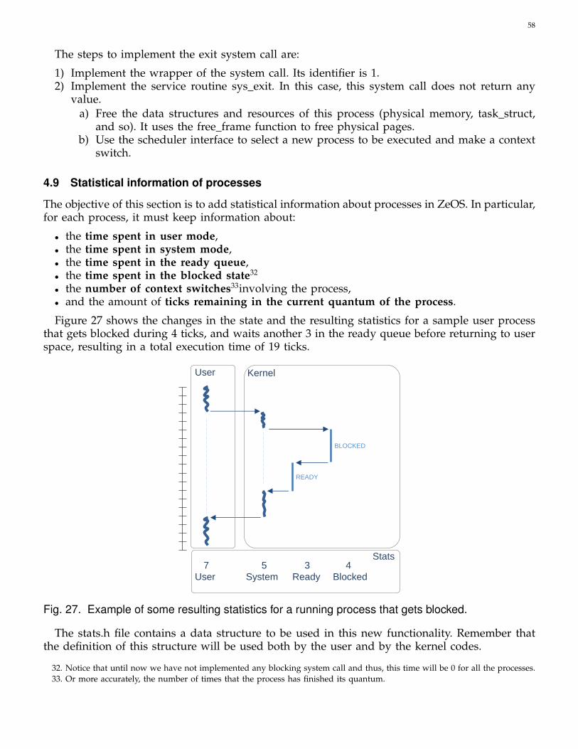
58
The steps to implement the exit system call are:
1) Implement the wrapper of the system call. Its identifier is 1.2) Implement the service routine sys_exit. In this case, this system call does not return any
value.a) Free the data structures and resources of this process (physical memory, task_struct,
and so). It uses the free_frame function to free physical pages.b) Use the scheduler interface to select a new process to be executed and make a context
switch.
4.9 Statistical information of processes
The objective of this section is to add statistical information about processes in ZeOS. In particular,for each process, it must keep information about:
• the time spent in user mode,• the time spent in system mode,• the time spent in the ready queue,• the time spent in the blocked state32
• the number of context switches33involving the process,• and the amount of ticks remaining in the current quantum of the process.
Figure 27 shows the changes in the state and the resulting statistics for a sample user processthat gets blocked during 4 ticks, and waits another 3 in the ready queue before returning to userspace, resulting in a total execution time of 19 ticks.
Kernel User
BLOCKED
READY
7 5 3 4 Stats
User System Ready Blocked
Fig. 27. Example of some resulting statistics for a running process that gets blocked.
The stats.h file contains a data structure to be used in this new functionality. Remember thatthe definition of this structure will be used both by the user and by the kernel codes.
32. Notice that until now we have not implemented any blocking system call and thus, this time will be 0 for all the processes.33. Or more accurately, the number of times that the process has finished its quantum.

59
struct stats {unsigned long user_ticks; /* Total ticks executing user code */unsigned long system_ticks; /* Total ticks executing system code */unsigned long blocked_ticks; /* Total ticks in the blocked state */unsigned long ready_ticks; /* Total ticks in the ready state */unsigned long elapsed_total_ticks; /* Ticks since the power on of the machine
until the beginning of the current state */unsigned long total_trans; /* Total transitions ready --> run */unsigned long remaining_ticks; /* Remaining ticks to end the quantum */
};
Therefore, you must modify the task_struct as required to keep the statistical data, implementthe code to keep updated this data for each process and implement a new system call to accessit.
We provide the implementation of the get_ticks function that returns the elapsed ticks sincethe machine was powered on. It has the following interface:
unsigned long get_ticks(void)
You can use this function to calculate the time spent in a section of your code, by invoking itat the beginning and end of the section and substracting both values.
Therefore, to keep the required statistical data, you must use this function each time a processchanges its state: 1) to update the amount of time spent in the current state that the process isleaving, and 2) to register into the field elapsed_total_ticks the starting time for the next state.For example, each time a process enters the system from the user space, you have to updatethe user_ticks field and to remember the starting time of the system state by performing thefollowing operations:
current_ticks = get_ticks();current->user_ticks += current_ticks - current-> elapsed_total_ticks;current->elapsed_total_ticks = current_ticks;
Figure 28 represents the states and transitions that we are considering at this stage of theproject, and the code involved to update the statitistical information about the execution time.Think carefully about where to insert each of these lines of code inside the ZeOS implementation.
The identifier of the get_stats system call is 35. This system call returns -1 if an error is produced,0 otherwise.
int get_stats(int pid, struct stats *st)pid: process identifier whose statistics get_stats will getst: pointer to the user buffer to store the statistics
The pid parameter contains the identifier of an alive process. The statistics of the process willbe returned through the st parameter. Be aware that st is a pointer to the user address space.Think about error cases and how to deal with them.

60
run-user
run-system
ready
a)
b)
c)
d)
a) user to system current->user_ticks += get_ticks()-current->elapsed_total_ticks; current->elapsed_total_ticks = get_ticks();
b) system to user current->system_ticks += get_ticks()-current->elapsed_total_ticks; current->elapsed_total_ticks = get_ticks();
c) system to ready current->system_ticks += get_ticks()-current->elapsed_total_ticks; current->elapsed_total_ticks = get_ticks();
d) ready to system current->ready_ticks += get_ticks()-current->elapsed_total_ticks; current->elapsed_total_ticks = get_ticks();
Fig. 28. States to consider when updating the execution time of a process
4.10 Work to do
This section describes the steps to follow to make ZeOS become multitasking. You will completethe ZeOS code to create/identify/switch/destroy processes and add a new process scheduler:
• Adapt the task_struct definition.• Initialize a free queue.• Initialize a ready queue.• Implement the initial processes initialization.• Implement the task_switch function.• Implement the inner_task_switch function.• Implement the getpid system call.• Implement the fork system call.• Implement process scheduling.• Implement the exit system call.• Implement the getstats system call.
5 ACKNOWLEDGEMENTS
This document was drawn up with the support of professors on previous courses: Julita Corbalán,Marisa Gil, Jordi Guitart, Gemma Reig, Amador Millán, Jordi García, Silvia LLorente, Pablo Chacínand Rubén González. The authors wish to thank A. Bartra, M. Muntanyá and O. Nieto for theircontributions.
This document has been improved by the following people:
• Albert Batalle Garcia (2011)

61
APPENDIX
Instructions to prepare the development environment:
1) Install basic development packages (gcc, ld, . . . )
sudo apt-get install build-essential
2) Install package for x86 tools (as86 and ld86)
sudo apt-get install bin86
3) Install needed libraries
apt-get -y install libx11-devapt-get -y install libgtk2.0-devapt-get -y install libreadline-dev
4) Download and install Bochs 2.6.7. You need to compile the Bochs source code in order touse the Bochs debugging facilities. It is necessary to activate some debugger options duringthe compilation because the option to use the debugger is disabled by default in the BochsBinary Standard Package.To enable the external GDB debugger you need to execute configure with parameter -enable-gdb-stub, and recompile Bochs:
$ ./configure --enable-gdb-stub --with-x --prefix=/opt/bochs_gdb$ make all install
If you want to activate the internal debugger you must recompile Bochs using:
$ ./configure --enable-debug --enable-disasm --enable-x86-debugger \--enable-readline --with-x --prefix=/opt/bochs$ make all install