yd style a-c centrifugal liquid chillers field re-assembly...
TRANSCRIPT

FIELD RE-ASSEMBLY FOR FORM 3 AND FORM 7 SHIPMENTMODEL YD CHILLERS - MOD A AND BWITH GRAPHIC CONTROL CENTER
AND ELECTRO-MECHANICAL STARTER
CENTRIFUGAL LIQUID CHILLERS
INSTALLATION INSTRUCTIONS Supersedes: 160.69-NM3 (912) Form 160.69-NM3 (715)
Issue Date: July 31, 2015

JOHNSON CONTROLS2
FORM 160.69-NM3 ISSUE DATE: 7/31/2015
This equipment is a relatively complicated apparatus. During rigging, installation, operation, maintenance, or service, individuals may be exposed to certain com-ponents or conditions including, but not limited to: heavy objects, refrigerants, materials under pressure, rotating components, and both high and low voltage. Each of these items has the potential, if misused or handled improperly, to cause bodily injury or death. It is the obligation and responsibility of rigging, instal-lation, and operating/service personnel to identify and recognize these inherent hazards, protect themselves, and proceed safely in completing their tasks. Failure to comply with any of these requirements could result in serious damage to the equipment and the property in
IMPORTANT!READ BEFORE PROCEEDING!
GENERAL SAFETY GUIDELINES
which it is situated, as well as severe personal injury or death to themselves and people at the site.
This document is intended for use by owner-authorized rigging, installation, and operating/service personnel. It is expected that these individuals possess independent training that will enable them to perform their assigned tasks properly and safely. It is essential that, prior to performing any task on this equipment, this individual shall have read and understood the on-product labels, this document and any referenced materials. This in-dividual shall also be familiar with and comply with all applicable industry and governmental standards and regulations pertaining to the task in question.
SAFETY SYMBOLS
The following symbols are used in this document to alert the reader to specific situations:
Indicates a possible hazardous situation which will result in death or serious injury if proper care is not taken.
Indicates a potentially hazardous situa-tion which will result in possible injuries or damage to equipment if proper care is not taken.
Identifies a hazard which could lead to damage to the machine, damage to other equipment and/or environmental pollu-tion if proper care is not taken or instruc-tions and are not followed.
Highlights additional information useful to the technician in completing the work being performed properly.
External wiring, unless specified as an optional connection in the manufacturer’s product line, is not to be connected inside the control cabinet. Devices such as relays, switches, transducers and controls and any external wiring must not be installed inside the micro panel. All wiring must be in accor-dance with Johnson Controls’ published specifications and must be performed only by a qualified electrician. Johnson Controls will NOT be responsible for damage/problems resulting from improper connections to the controls or application of improper control signals. Failure to follow this warn-ing will void the manufacturer’s warranty and cause serious damage to property or personal injury.

JOHNSON CONTROLS 3
FORM 160.69-NM3 ISSUE DATE: 7/31/2015
MANUAL DESCRIPTION FORM NUMBER
Unit Installation 160.69-N1
OptiViewTM Operation 160.69-O2
Shipping Damage Claim Policy 50.15-NM
CHANGEABILITY OF THIS DOCUMENT
In complying with Johnson Controls’ policy for con-tinuous product improvement, the information con-tained in this document is subject to change without notice. Johnson Controls makes no commitment to update or provide current information automatically to the manual or product owner. Updated manuals, if applicable, can be obtained by contacting the nearest Johnson Controls Service office or accessing the John-son Controls QuickLIT website at http://cgproducts.johnsoncontrols.com.
It is the responsibility of rigging, lifting, and operating/ service personnel to verify the applicability of these documents to the equipment. If there is any question
regarding the applicability of these documents, rig-ging, lifting, and operating/service personnel should verify whether the equipment has been modified and if current literature is available from the owner of the equipment prior to performing any work on the chiller.
CHANGE BARSRevisions made to this document are indicated with a line along the left or right hand column in the area the revision was made. These revisions are to technical in-formation and any other changes in spelling, grammar or formatting are not included.
ASSOCIATED LITERATURE

JOHNSON CONTROLS4
FORM 160.69-NM3 ISSUE DATE: 7/31/2015
NOMENCLATURE
MOTOR CODE60 Hz 50 HzCW 5CSCX 5CTCY 5CUCZ 5CVCA 5CWCB 5CXDA 5DADB 5DBDC 5DCDD 5DDDE 5DEDF 5DF
5DGDH 5DHDJ 5DJ
YD XF XA J2 – CA A
POWER SUPPLY- for 60 Hz5 for 50 Hz
DESIGN LEVEL
MODEL
CONDENSER CODEXA, XB, XC, XD, YA, YB, YC, YD, ZA, ZB, ZC, ZD, AA, AB, AC, AD
EVAPORATOR CODEXF, XH YF, YG, YH, ZF, ZG, ZH AF, AG, AH
COMPRESSOR CODEJ1, J2, J3, J4, J5
MOTOR CODE60 Hz 50 HzCW 5CSCX 5CTCY 5CUCZ 5CVCA 5CWCB 5CXDA 5DADB 5DBDC 5DCDD 5DDDE 5DEDF 5DF
5DGDH 5DHDJ 5DJDK 5DKDL 5DL
COMPRESSOR CODEJ1, J2, J3, J4, J5, J7
YD XH XD J2 – DA B
POWER SUPPLY– for 60 Hz5 for 50 Hz
DESIGN LEVEL
CONDENSER CODEKB, KC, KD, KE, K2, K3, K4, K5HB, HC, HD, HE, H2, H3, H4, H5GB, GC, GD, GE, G2, G3, G4, G5FB, FC, FD, FE, F2, F3, F4, F5EB, EC, ED, EE, E2, E3, E4, E5DB, DC, DD, DE, D2, D3, D4, D5CB, CC, CD, C2, C3, C4BB, BC, BD, BE, B2, B3, B4, B5
EVAPORATOR CODEKB, KC, KD, K2, K3, K4HB, HC, HD, H2, H3, H4GB, GC, GD, G2, G3, G4FB, FC, FD, F2, F3, F4EB, EC, ED, E2, E3, E4DB, DC, DD, D2, D3, D4CB, CC, CD, C2, C3, C4BB, BC, BD, B2, B3, B4MODEL

JOHNSON CONTROLS 5
FORM 160.69-NM3 ISSUE DATE: 7/31/2015
LIST OF FIGURES
FIGURE 1 - Front View Of Assembled Unit ...............................................................................................................7FIGURE 2 - Form 7 Shipment ...................................................................................................................................8FIGURE 3 - Rigging – Compressor/Motor Assembly ................................................................................................9FIGURE 4 - Re-Assembly .......................................................................................................................................10FIGURE 5 - System Piping ..................................................................................................................................... 11FIGURE 6 - System Piping ..................................................................................................................................... 11FIGURE 7 - Liquid Line Re-Assembly .....................................................................................................................12FIGURE 8 - Oil Pump Housing ................................................................................................................................13

JOHNSON CONTROLS6
FORM 160.69-NM3 ISSUE DATE: 7/31/2015
THIS PAGE INTENTIONALLY LEFT BLANK.

JOHNSON CONTROLS 7
FORM 160.69-NM3 ISSUE DATE: 7/31/2015
GENERALThis instruction explains the procedure to be used for reassembling the Model YD Chiller shipped disassem-bled (Shipping Form 3 and 7).
Chillers MUST be field reassembled un-der the supervision of a Johnson Controls representative.
For Installation Instructions other than unit assembly, refer to Form 160.69-N1 or N2.
FORMS OF SHIPMENT
Form 3 – Driveline Separate From ShellsShipped as three major assemblies. Unit first factory assembled, refrigerant piped, wired and leak tested; then dismantled for shipment. Close-coupled compres-sor/open motor assemblies are removed from shells and skidded. Evaporator/condenser is not skidded.
All wiring essential with the compressors is left on them, and all conduit is left on the shells. All openings on the compressors and shells are closed and charged with dry nitrogen (2 to 3 PSIG).
Miscellaneous packaging of the Control Center, oil eductor filter, tubing, water temperature controls, wir-ing, oil, isolators, etc. Refrigerant charge shipped in appropriate cylinders.
Form 7 – Split ShellsShipped as four major assemblies. Unit first factory assembled, refrigerant piped, wired and leak tested; then dismantled for shipment. Close-coupled compres-sor/open motor assemblies removed from shells and skidded.
Evaporator and condenser shells are separated at tube sheets and are not skidded. Refrigerant lines between shells are flanged and capped; tube sheets are also bolt-ed, requiring no welding.
FIGURE 1 - FRONT VIEW OF ASSEMBLED UNIT
LD09115
COMPRESSOR
MOTOR
GRAPHICCONTROLCENTER
VSOPPANEL
EVAPORATOR
CONDENSER
COMPRESSOR
MOTOR

JOHNSON CONTROLS8
FORM 160.69-NM3 ISSUE DATE: 7/31/2015
All wiring essential with the compressors is left on them. All wiring harnesses on shells are removed.
All openings on the compressors and shells are closed and charged with dry nitrogen (2 or 3 PSIG).
Miscellaneous packaging of Control Center, oil educ-tor filter, tubing, water temperature controls, wiring, oil, isolators, etc. Refrigerant charge shipped in appro-priate cylinders.
When more than one chiller is involved, the major parts of each unit will be marked to prevent the mixing of assem-blies (Piping and Wiring Drawings to be furnished by YORK).
INSPECTION – DAMAGE – SHORTAGEThe unit shipment should be checked on arrival to see that all major pieces, boxes and crates are received. Each unit should be checked on the trailer or rail car when received, before unloading, for any visible signs of damage. Any damage or signs of possible damage must be reported to the transportation company imme-diately for their inspection.
YORK will not be responsible for any damage in shipment of at job site or loss of parts. (Refer to Shipping Damage Claims, Form 50.15-NM).
When received at the job site, all containers should be opened and contents checked against the packing list. Any material shortage should be reported to YORK immediately (refer to Shipping Damage Claims, Form 50.15-NM).
DATA PLATESA unit data plate is mounted on the Control Center as-sembly of each unit, giving unit model number; design working pressure; water passes; refrigerant charge; se-rial numbers; and motor power characteristics and con-nection diagrams.
A Control Panel data plate, which includes control panel part number and serial number is also included.
FIGURE 2 - FORM 7 SHIPMENT
LD03865
CONDENSER
COOLER
5/8" X 2-1/2" BOLTS, LOCKWASHERS, &HEX NUTS

JOHNSON CONTROLS 9
FORM 160.69-NM3 ISSUE DATE: 7/31/2015
RE-ASSEMBLYThe following is a step-by-step procedure to be used to assemble the chiller. Refer to Installation Instruction, Form 160.69-N1 or N2 for other instructions.
Form 7 Shipment(See Figure 2 on page 8)
1. Locate the evaporator and condenser shells in their final position.
2. Bolt the tube sheets together as shown in Figure 2 on page 8. Note that the outside surfaces of the tube sheets must be flush.
FORM 3 AND FORM 7 SHIPMENT1. Level the shells in both directions. The longitu-
dinal alignment of the shell should be checked by placing a level on the top of the shell, next to the discharge connection. The transverse align-ment should be checked by placing a level on the tops of both end sheets. Refer to “Installation In-struction”, Form 160.69-N1 or N2 for additional instructions to level the unit. After the shell is lev-eled, wedge and shim each corner of the shell to solidly support it while assembling the other parts.
2. Lift a compressor/motor assembly and remove the packing materials (refer to Figure 3 on page 9 for rigging). Carefully lower the compressor/mo-tor assembly on to the supports on the condenser and evaporator. Fasten with the proper hardware. Do not tighten the bolts until all connections are made to the compressor.
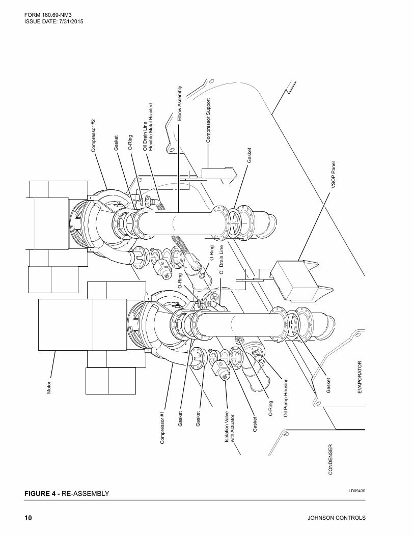
3. Bolt the suction lines between the compressors and the evaporator using the proper gaskets and hardware, see Figure 4 on page 10.
4. Install the isolation valves between the compres-sors and the condenser using proper gaskets and hardware, see Figure 4 on page 10.
5. Connect the oil drain lines between the com-pressors oil drain flanges and oil pump housing flanges. Be sure to install the proper gaskets and hardware, see Figure 4 on page 10 and Figure 7 on page 12.
6. Complete the refrigerant liquid piping beneath the evaporator and condenser. Be sure the fill piece, orifice plate, gaskets and hardware are properly installed, see Figure 6 on page 11.
7. Tighten all hardware installed from the previous steps 2 thru 8.
8. Assemble the Control Center to unit.
9. Assemble the VS Oil Pump Control Panel.
10. Install the refrigerant piping and oil return system filters.
11. Pressure test. NOTE: Relief valves must be plugged (or capped) (refer to Form 160.69-O2).
12. Evacuate and charge with refrigerant (refer to Form 160.69-O2).
13. All Units – Complete installation and finally level the unit per “Installation Instruction”, Form 160.69-N1 or N2.
FIGURE 3 - RIGGING – COMPRESSOR/MOTOR ASSEMBLY
LD02140
JOHNSON CONTROLS10
FORM 160.69-NM3 ISSUE DATE: 7/31/2015
FIGURE 4 - RE-ASSEMBLY LD09430
Com
pres
sor #
2
Com
pres
sor #
1
Mot
or
Isol
atio
n Va
lve
with
Act
uato
r
CO
ND
EN
SE
R
EVA
PO
RAT
OR
VS
OP
Pan
el
Com
pres
sor S
uppo
rt
Oil
Dra
in L
ine
Flex
ible
Met
al B
raid
ed
Oil
Dra
in L
ine
O-R
ing
O-R
ing
O-R
ing
O-R
ing
Gas
ket
Gas
ket
Gas
ket
Gas
ket
Gas
ket
Gas
ket
Oil
Pum
p H
ousi
ng
Elb
ow A
ssem
bly

JOHNSON CONTROLS 11
FORM 160.69-NM3 ISSUE DATE: 7/31/2015
FIGURE 5 - SYSTEM PIPING
FIGURE 6 - SYSTEM PIPING LD09433
Compressor #2Compressor #1
VSOP Panel
LD09431
VSOP Panel
Compressor #1Isolation Valvewith Actuator
Isolation Valvewith Actuator
Compressor #2

FIGURE 7 - LIQUID LINE RE-ASSEMBLY
LD09435

FIGURE 8 - OIL PUMP HOUSINGLD09442

P.O. Box 1592, York, Pennsylvania USA 17405-1592 800-861-1001 Subject to change without notice. Printed in USACopyright © by Johnson Controls 2015 www.johnsoncontrols.com ALL RIGHTS RESERVEDForm 160.69-NM3 (715)Issue Date: July 31, 2015 Supersedes: 160.69-NM3 (912)