yaris 2006 - cold air intake section i – installation...
TRANSCRIPT

YARIS 2006 - COLD AIR INTAKE Section I – Installation Preparation
Page 1 of 13 pages DIO
Part Number(s): PTR03-52070 Kit Contents
Item # Quantity Reqd. Description 1 1 Upper Intake Pipe 2 1 Lower Intake Pipe 3 1 TRD Air Filter, 2.25" 4 1 Bypass Valve Assy., 2.25” 5 1 Hardware Bag
Hardware Bag Contents Item # Quantity Reqd. Description 1 1 2.25" x 2.0” Hose 2 2 Hose Clamp, 2.25” 3 1 Hose Clamp, 2.15” – 3.00” 4 2 Socket Bolt, 8-32 x 5/16" 5 1 Bolt, M5x.8x12mm 6 1 Washer, M5 Split Lock 7 1 Mount, Rubber 1” x 8mm 8 1 Nut, Hex Serrated 8mm 9 1 Washer, 8mm 10 3 Wire Ties, 8” Tree Push Mount 11 2 TRD Decals 12 1 Instruction Manual
Additional Items Required For Installation Item # Quantity Reqd. Description
Recommended Tools Safety Tools Vehicle Protection Fender Covers Special Tools None Required Installation Tools 8mm socket ¼” drive 10mm socket ¼” drive ¼” drive ratchet ¼” drive extension 6” long 12mm socket 3/8” drive 3/8” drive ratchet 3/8” drive extension 3” long Phillips head screwdriver #2 Nut driver 8mm 8mm combination wrench 13mm combination wrench Torque wrench lbf.-in. Jack and jack stands or chassis lift Allen wrench 9/64” Side cutter Pliers Special Chemicals Glass cleaner
General Applicability
All Yaris: Hatchback and Sedan
Conflicts Note: None
Recommended Sequence of Installation If any other accessories are to be installed, it is recommended they be installed in the order described below to ease installation and/or avoid redundant work.
Item # Accessory
*Mandatory
Legend Please see page 12 for important “Care and Maintenance” information!
STOP STOP: Damage to the vehicle may occur. Do not proceed until process has been complied with. OPERATOR SAFETY: Use caution to avoid risk of injury CRITICAL PROCESS: Proceed with caution to ensure a quality installation. GENERAL PROCESS: This highlights specific processes to ensure a quality installation. TOOLS & EQUIPMENT: This calls out the specific tools and equipment required for this process
Issue A: 5/11/06
YARIS 2006 - COLD AIR INTAKE Section II – Installation
A. Check Kit Contents
1. Check kit for contents and damage.
B. Vehicle and Parts Preparation
1. Completely read instructions and familiarize yourself with the installation before beginning.
2. Open hood.
STOP 3. Apply vehicle protection to prevent damage to painted surfaces.
STOP 4. Remove negative battery cable from terminal.
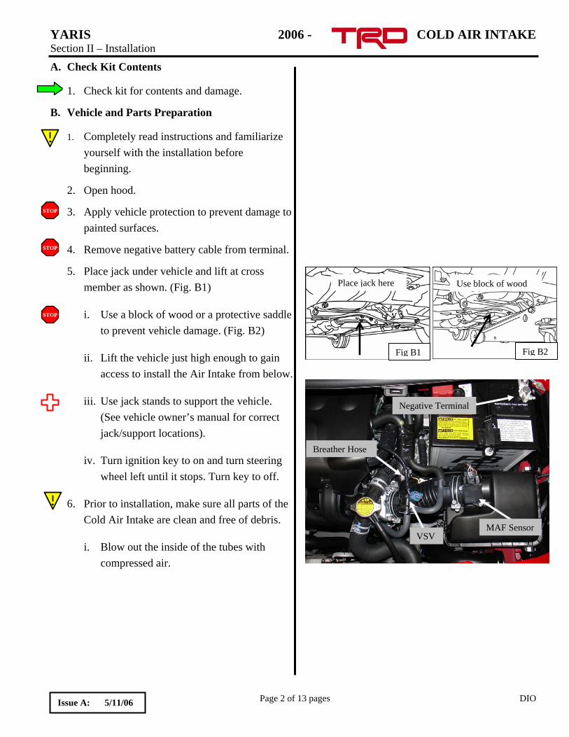
5. Place jack under vehicle and lift at cross member as shown. (Fig. B1)
Fig B2
Use block of wood
Fig B1
Place jack here
STOP i. Use a block of wood or a protective saddle to prevent vehicle damage. (Fig. B2)
ii. Lift the vehicle just high enough to gain access to install the Air Intake from below.
Negative Terminal
Breather Hose
VSV MAF Sensor
iii. Use jack stands to support the vehicle. (See vehicle owner’s manual for correct jack/support locations).
iv. Turn ignition key to on and turn steering wheel left until it stops. Turn key to off.
6. Prior to installation, make sure all parts of the Cold Air Intake are clean and free of debris.
i. Blow out the inside of the tubes with compressed air.
Page 2 of 13 pages DIO Issue A: 5/11/06
YARIS 2006 - COLD AIR INTAKE Section II – Installation
C. Remove Factory Components
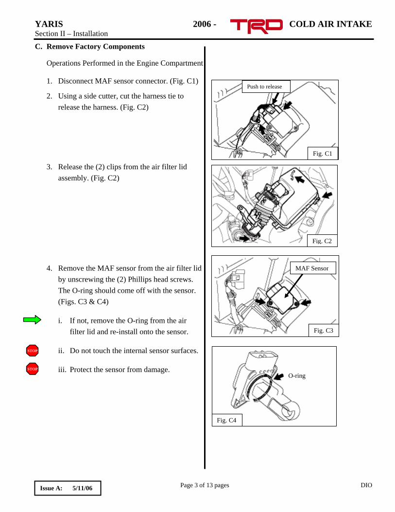
Operations Performed in the Engine Compartment 1. Disconnect MAF sensor connector. (Fig. C1)
Push to release
Fig. C1
2. Using a side cutter, cut the harness tie to release the harness. (Fig. C2)
3. Release the (2) clips from the air filter lid assembly. (Fig. C2)
Fig. C2
4. Remove the MAF sensor from the air filter lid by unscrewing the (2) Phillips head screws. The O-ring should come off with the sensor. (Figs. C3 & C4)
Fig. C3
MAF Sensor
i. If not, remove the O-ring from the air filter lid and re-install onto the sensor.
STOP ii. Do not touch the internal sensor surfaces.
Fig. C4
O-ring STOP
Page 3 of 13 pages DIO
iii. Protect the sensor from damage.
Issue A: 5/11/06

YARIS 2006 - COLD AIR INTAKE Section II – Installation
5. Disconnect the hose from the VSV. Electrical connector Top hose
for VSV
Breather hose
Fig. C5 Front hose for VSV
i. Release the hose clamp tension from the top hose and pull hose off VSV. (Fig. C5)
6. Remove the valve cover breather hose from the air inlet hose. (Fig. C5)
i. If needed, use pliers to release tension on spring clamp before removing hose.
7. Loosen the rubber inlet hose to throttle body clamp at the throttle body. (Fig. C6)
Fig. C6
8. Grasp the VSV steel mount and pull it forward towards the front grille until the mount and VSV is detached from the rubber intake hose.
9. Open the air filter lid and remove the entire air filter lid assembly and air filter element.
10. Use pliers to unclip the VSV wire loom clip from the steel mount. (Fig. C7)
Phillips head screw
Unclip wire loom here
Fig. C7
11. Use a Phillips head screwdriver to remove the steel VSV mount from the VSV. Save steel mount for later use. (Fig. C7)
Page 4 of 13 pages DIO Issue A: 5/11/06
YARIS 2006 - COLD AIR INTAKE Section II – Installation
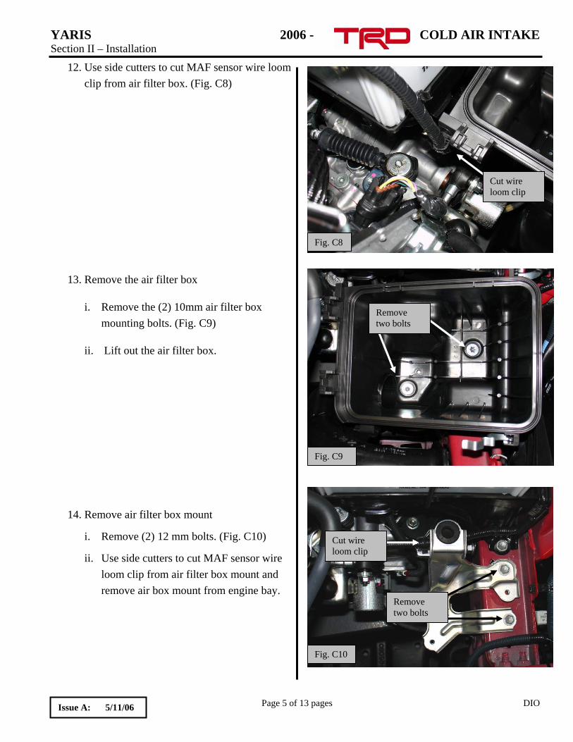
12. Use side cutters to cut MAF sensor wire loom clip from air filter box. (Fig. C8)
Cut wire loom clip
Fig. C8
Remove two bolts
Fig. C9
13. Remove the air filter box
i. Remove the (2) 10mm air filter box mounting bolts. (Fig. C9)
ii. Lift out the air filter box.
Cut wire loom clip
Fig. C10
Remove two bolts
14. Remove air filter box mount
i. Remove (2) 12 mm bolts. (Fig. C10)
ii. Use side cutters to cut MAF sensor wire loom clip from air filter box mount and remove air box mount from engine bay.
Page 5 of 13 pages DIO Issue A: 5/11/06
YARIS 2006 - COLD AIR INTAKE Section II – Installation
D. Install TRD Air Intake
Orient hose clamp
2nd clamp is loose
Rubber hose
Fig. D1
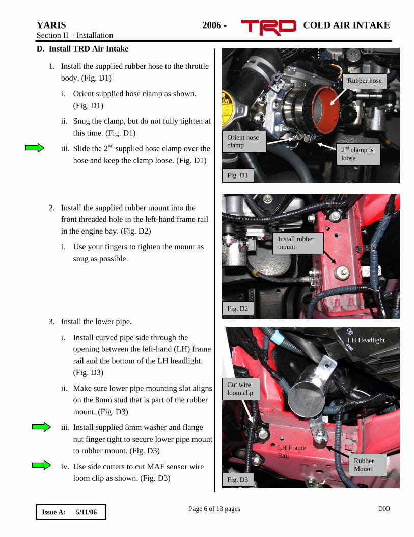
1. Install the supplied rubber hose to the throttle body. (Fig. D1)
i. Orient supplied hose clamp as shown. (Fig. D1)
ii. Snug the clamp, but do not fully tighten at this time. (Fig. D1)
iii. Slide the 2nd supplied hose clamp over the hose and keep the clamp loose. (Fig. D1)
Install rubber mount
Fig. D2
2. Install the supplied rubber mount into the front threaded hole in the left-hand frame rail in the engine bay. (Fig. D2)
i. Use your fingers to tighten the mount as snug as possible.
3. Install the lower pipe.
Cut wire loom clip
Fig. D3
LH FRail
rame
Rubber Mount
LH Headlight i. Install curved pipe side through the opening between the left-hand (LH) frame rail and the bottom of the LH headlight. (Fig. D3)
ii. Make sure lower pipe mounting slot aligns on the 8mm stud that is part of the rubber mount. (Fig. D3)
iii. Install supplied 8mm washer and flange nut finger tight to secure lower pipe mount to rubber mount. (Fig. D3)
iv. Use side cutters to cut MAF sensor wire loom clip as shown. (Fig. D3)
Page 6 of 13 pages DIO Issue A: 5/11/06
YARIS 2006 - COLD AIR INTAKE Section II – Installation
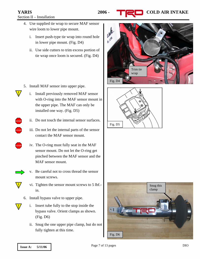
4. Use supplied tie wrap to secure MAF sensor wire loom to lower pipe mount.
Fig. D4
Trim tie wrap
Fig. D5
i. Insert push-type tie wrap into round hole in lower pipe mount. (Fig. D4)
ii. Use side cutters to trim excess portion of tie wrap once loom is secured. (Fig. D4)
5. Install MAF sensor into upper pipe.
i. Install previously removed MAF sensor with O-ring into the MAF sensor mount in the upper pipe. The MAF can only be installed one way. (Fig. D5)
ii. Do not touch the internal sensor surfaces. STOP
iii. Do not let the internal parts of the sensor contact the MAF sensor mount.
STOP
iv. The O-ring must fully seat in the MAF sensor mount. Do not let the O-ring get pinched between the MAF sensor and the MAF sensor mount.
STOP
v. Be careful not to cross thread the sensor mount screws.
Snug this clamp
Fig. D6
vi. Tighten the sensor mount screws to 5 lbf.-in.
6. Install bypass valve to upper pipe.
i. Insert tube fully to the stop inside the bypass valve. Orient clamps as shown. (Fig. D6)
ii. Snug the one upper pipe clamp, but do not fully tighten at this time.
Page 7 of 13 pages DIO Issue A: 5/11/06

YARIS 2006 - COLD AIR INTAKE Section II – Installation
7. Install upper pipe.
Fig. D7
i. Move upper pipe into position and align throttle body inlet side of pipe to hose installed on throttle body. (Fig. D7)
ii. Insert lower pipe into bypass valve already connected to upper pipe. (Fig. D7)
iii. Make sure lower pipe is fully inserted into bypass valve. The pipe will contact the step inside the bypass valve at full insertion.
iv. If the alignment or clocking of the upper pipe is not correct, then grasp both the upper and lower pipes and rotate the upper pipe into position.
v. When both pipes are aligned, insert the upper pipe into the throttle body hose. (Fig. D7)
vi. Tighten both hose clamps on the upper pipe until they are snug. Do not fully tighten clamps at this time.
Operations Performed From Below
Fig. D8
Remove three screws
8. Partially remove the LH inner fender panel.
i. Remove the (3) 10mm screws. (Fig. D8)
Page 8 of 13 pages DIO Issue A: 5/11/06
YARIS 2006 - COLD AIR INTAKE Section II – Installation
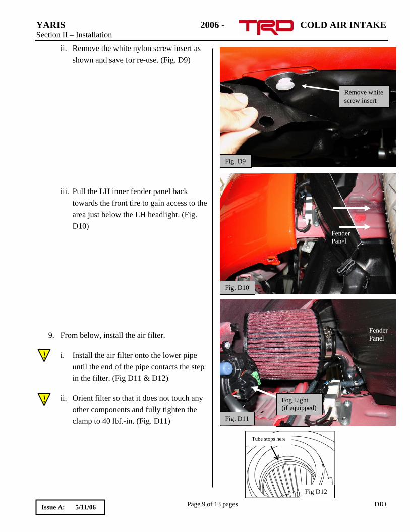
ii. Remove the white nylon screw insert as shown and save for re-use. (Fig. D9)
Fig. D9
Remove white screw insert
FenderP
anel
Fig. D10
iii. Pull the LH inner fender panel back towards the front tire to gain access to the area just below the LH headlight. (Fig. D10)
Fig. C14
FenderPa
nel
Fog Light (if equipped)
Fig. D11
9. From below, install the air filter.
i. Install the air filter onto the lower pipe until the end of the pipe contacts the step in the filter. (Fig D11 & D12)
ii. Orient filter so that it does not touch any other components and fully tighten the clamp to 40 lbf.-in. (Fig. D11)
Page 9 of 13 pages DIO
Fig D12
Tube stops here
Issue A: 5/11/06
YARIS 2006 - COLD AIR INTAKE Section II – Installation
10. Re-install LH inner fender panel.
i. Align panel back into place.
ii. Do not re-install the screw insert or (3) 10mm screws at this time.
11. Check area around air filter to make sure air filter does not touch any other vehicle components.
12. Adjust filter and lower pipe as necessary to gain any needed clearance.
Operations Performed From Above
13. Use a 13mm combination wrench to tighten the flanged nut to secure lower pipe to frame rail.
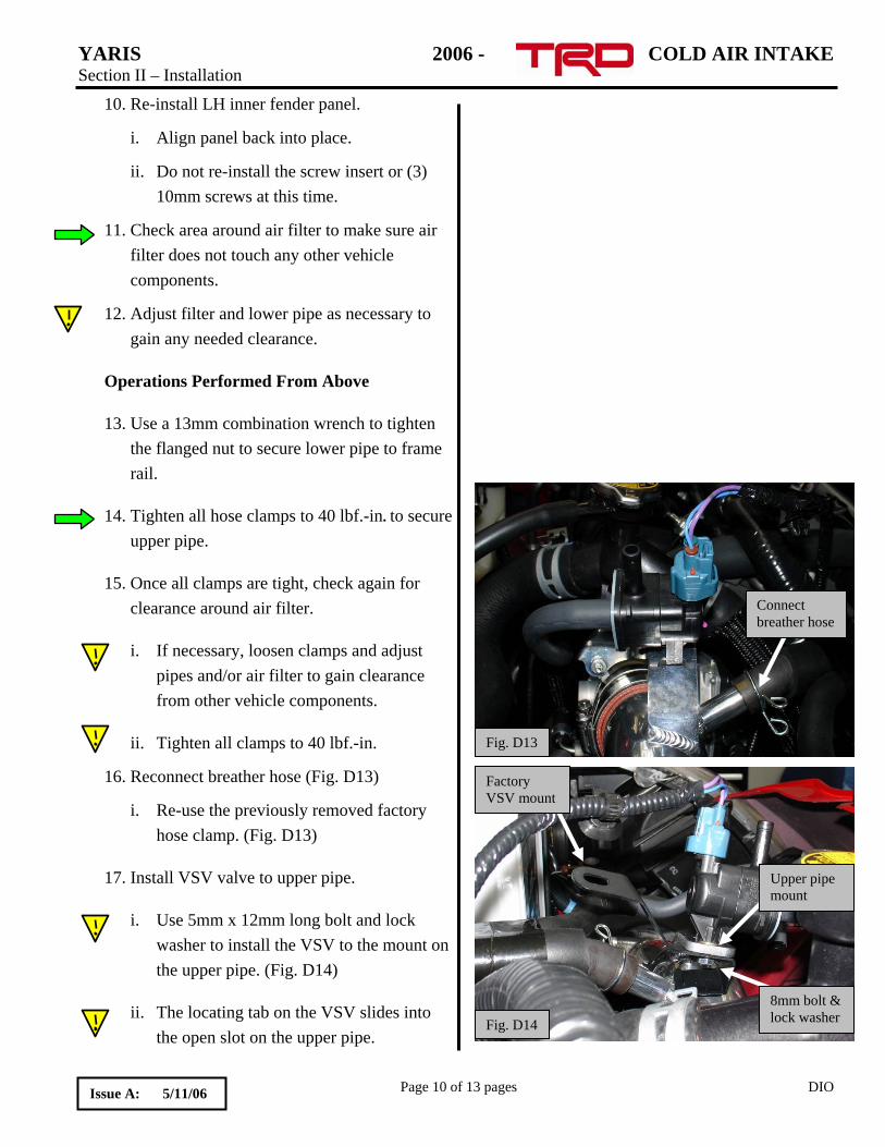
Connect breather hose
Fig. D13
14. Tighten all hose clamps to 40 lbf.-in. to secure upper pipe.
15. Once all clamps are tight, check again for clearance around air filter.
i. If necessary, loosen clamps and adjust pipes and/or air filter to gain clearance from other vehicle components.
ii. Tighten all clamps to 40 lbf.-in.
Upper pipe mount
8mm bolt & lock washer
Factory VSV mount
Fig. D14
16. Reconnect breather hose (Fig. D13)
i. Re-use the previously removed factory hose clamp. (Fig. D13)
17. Install VSV valve to upper pipe.
i. Use 5mm x 12mm long bolt and lock washer to install the VSV to the mount on the upper pipe. (Fig. D14)
ii. The locating tab on the VSV slides into the open slot on the upper pipe.
Page 10 of 13 pages DIO Issue A: 5/11/06
YARIS 2006 - COLD AIR INTAKE Section II – Installation
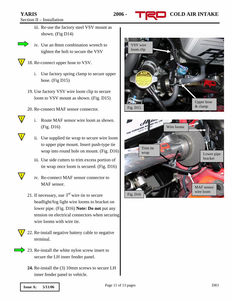
iii. Re-use the factory steel VSV mount as shown. (Fig D14)
VSV wire loom clip
Upper hose & clamp Fig. D15
iv. Use an 8mm combination wrench to tighten the bolt to secure the VSV
18. Re-connect upper hose to VSV.
i. Use factory spring clamp to secure upper hose. (Fig D15)
19. Use factory VSV wire loom clip to secure loom to VSV mount as shown. (Fig. D15)
20. Re-connect MAF sensor connector.
i. Route MAF sensor wire loom as shown. (Fig. D16)
Lower pipe bracket
Wire looms
MAF sensor wire loom
Trim tie wrap
Fig. D16
ii. Use supplied tie wrap to secure wire loom to upper pipe mount. Insert push-type tie wrap into round hole on mount. (Fig. D16)
iii. Use side cutters to trim excess portion of tie wrap once loom is secured. (Fig. D16)
iv. Re-connect MAF sensor connector to MAF sensor.
21. If necessary, use 3rd wire tie to secure headlight/fog light wire looms to bracket on lower pipe. (Fig. D16) Note: Do not put any tension on electrical connectors when securing wire looms with wire tie.
22. Re-install negative battery cable to negative terminal.
23. Re-install the white nylon screw insert to secure the LH inner fender panel.
24. Re-install the (3) 10mm screws to secure LH inner fender panel to vehicle.
Page 11 of 13 pages DIO Issue A: 5/11/06
YARIS 2006 - COLD AIR INTAKE Section II – Installation
25. Installer – The installation manual contains important “Care and Maintenance” information. Place the instruction manual in the glove box for future customer reference.
Section III – Care and Maintenance
Air Filter Maintenance
Service Intervals- Service your TRD filter element with TRD's filter cleaning kit (Toyota p/n PTR05-00000-CL) at least every 50,000 miles to maintain optimum performance. We recommend that TRD filter elements be serviced every 30,000 miles on off-road and high-performance street applications.
If you live in a region with extremely fine dust (arid or desert climates for example), follow the recommended schedule for off-road and high-performance vehicles.
Always inspect your filter element whenever you change your oil.
Do not over-oil the filter. This could contaminate the MAF sensor and cause the MIL (Malfunction Indicator Lamp) to illuminate and require non-warrantable repairs.
Caring For The Finish On Your TRD Cold Air Intake.
TRD polished intakes have a protective clear powdercoat finish that ensures a maintenance free shine.
To clean your polished intake, simply spray with window cleaner and wipe with a soft, clean terry-cloth towel.
NEVER use harsh chemicals or metal polish on TRD polished intakes. Harsh chemicals and metal polishes will permanently damage the finish of your cold air intake system.
Page 12 of 13 pages DIO Issue A: 5/11/06
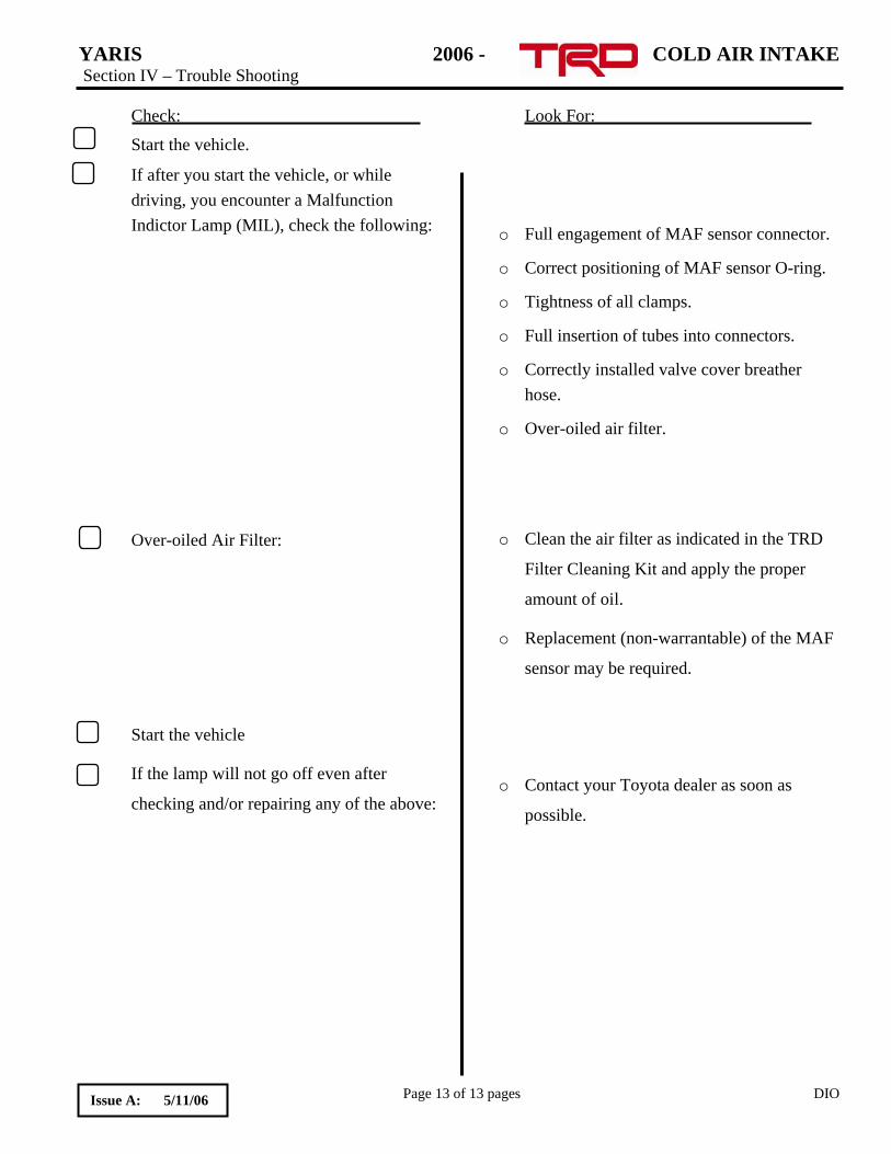
YARIS 2006 - COLD AIR INTAKE Section IV – Trouble Shooting Check: Look For:
Page 13 of 13 pages DIO
Start the vehicle.
If after you start the vehicle, or while driving, you encounter a Malfunction Indictor Lamp (MIL), check the following:
o Full engagement of MAF sensor connector.
o Correct positioning of MAF sensor O-ring.
o Tightness of all clamps.
o Full insertion of tubes into connectors. o Correctly installed valve cover breather
hose.
o Over-oiled air filter.
o Clean the air filter as indicated in the TRD
Filter Cleaning Kit and apply the proper
amount of oil.
Over-oiled Air Filter:
o Replacement (non-warrantable) of the MAF
sensor may be required.
Start the vehicle
If the lamp will not go off even after
checking and/or repairing any of the above:
o Contact your Toyota dealer as soon as
possible.
Issue A: 5/11/06