y201-en2-03.book seite 427 donnerstag, 13. april 2006 … · 429 industrial communication...
TRANSCRIPT
427
Ind
ust
rial
C
om
mu
nic
atio
n
Industrial Communication
Industrial Communication 428Ethernet 430Controller Link 432Serial Communication 437PROFIBUS-DP 440DeviceNet 443
DeviceNet product overview 448CompoBus/S 455
CompoBus/S product overview 459MechatroLink II 462
Y201-EN2-03.book Seite 427 Donnerstag, 13. April 2006 9:40 09
428 Industrial Communication
Industrial CommunicationOverview
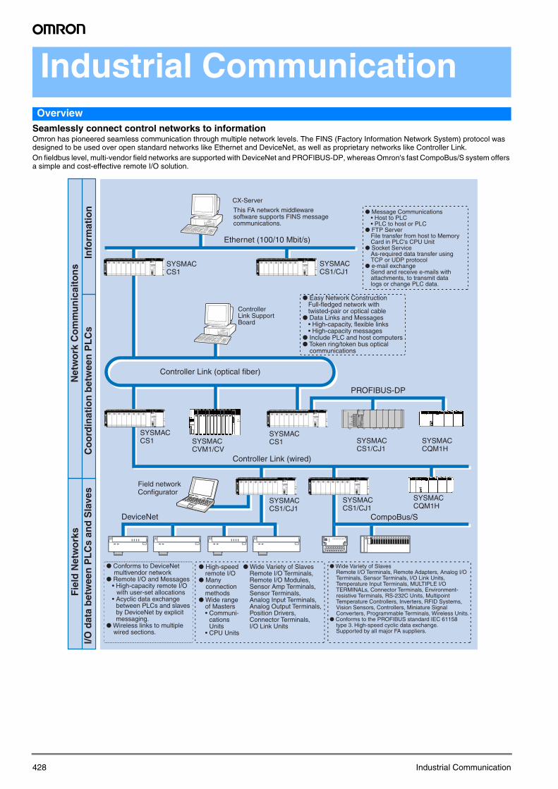
Seamlessly connect control networks to informationOmron has pioneered seamless communication through multiple network levels. The FINS (Factory Information Network System) protocol was designed to be used over open standard networks like Ethernet and DeviceNet, as well as proprietary networks like Controller Link. On fieldbus level, multi-vendor field networks are supported with DeviceNet and PROFIBUS-DP, whereas Omron's fast CompoBus/S system offers a simple and cost-effective remote I/O solution.
CX-Server
Ethernet (100/10 Mbit/s)
This FA network middlewaresoftware supports FINS messagecommunications.
● Message Communications• Host to PLC• PLC to host or PLC
● FTP ServerFile transfer from host to Memory Card in PLC's CPU Unit
● Socket ServiceAs-required data transfer usingTCP or UDP protocol
● e-mail exchangeSend and receive e-mails with attachments, to transmit data logs or change PLC data.
● Easy Network ConstructionFull-fledged network with twisted-pair or optical cable
● Data Links and Messages • High-capacity, flexible links• High-capacity messages
● Include PLC and host computers● Token ring/token bus optical
communications
Controller Link (optical fiber)
SYSMAC CS1
SYSMAC CS1/CJ1
ControllerLink Support Board
PROFIBUS-DP
SYSMAC CS1
SYSMAC CS1
SYSMAC CS1/CJ1
SYSMAC CS1/CJ1
SYSMAC CVM1/CV
SYSMAC CQM1H
SYSMAC CS1/CJ1
SYSMAC CQM1H
Field networkConfigurator
DeviceNet CompoBus/S
Controller Link (wired)
● Conforms to DeviceNet multivendor network
● Remote I/O and Messages • High-capacity remote I/O
with user-set allocations• Acyclic data exchange
between PLCs and slaves by DeviceNet by explicit messaging.
● Wireless links to multiple wired sections.
● Wide Variety of SlavesRemote I/O Terminals, Remote Adapters, Analog I/O Terminals, Sensor Terminals, I/O Link Units, Temperature Input Terminals, MULTIPLE I/O TERMINALs, Connector Terminals, Environment-resistive Terminals, RS-232C Units, Multipoint Temperature Controllers, Inverters, RFID Systems, Vision Sensors, Controllers, Miniature Signal Converters, Programmable Terminals, Wireless Units.
● Conforms to the PROFIBUS standard IEC 61158 type 3. High-speed cyclic data exchange. Supported by all major FA suppliers.
● High-speedremote I/O
● Many connectionmethods
● Wide rangeof Masters• Communi-
cationsUnits
• CPU Units
● Wide Variety of SlavesRemote I/O Terminals, Remote I/O Modules, Sensor Amp Terminals, Sensor Terminals,Analog Input Terminals, Analog Output Terminals, Position Drivers, Connector Terminals, I/O Link Units
Info
rmat
ion
Co
ord
inat
ion
bet
wee
n P
LC
sN
etw
ork
Co
mm
un
icai
ton
sI/O
dat
a b
etw
een
PL
Cs
and
Sla
ves
Fie
ld N
etw
ork
s
POWER
PA205R
DC24VAC240V
OUTPUTRUN
INPUTAC100-240V
L2/N
L1
CONTROLLER
CJ1G-CPU44SYSMAC
PROGRAMMABLEERR/ALM
RUN
COMM
INHPRPHL
OPEN
PERIPHERAL
BUSY
MCPWR
PORT
Y201-EN2-03.book Seite 428 Donnerstag, 13. April 2006 9:40 09
429
Ind
ust
rial
C
om
mu
nic
atio
n
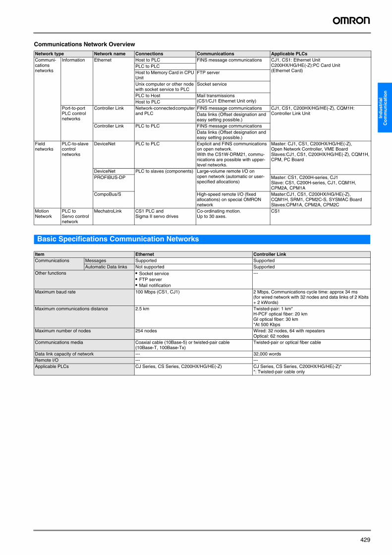
Communications Network Overview
Basic Specifications Communication Networks
Network type Network name Connections Communications Applicable PLCsCommuni-cations networks
Information Ethernet Host to PLC FINS message communications CJ1, CS1: Ethernet UnitC200HX/HG/HE(-Z):PC Card Unit(Ethernet Card)
PLC to PLCHost to Memory Card in CPU Unit
FTP server
Unix computer or other node with socket service to PLC
Socket service
PLC to Host Mail transmissions (CS1/CJ1 Ethernet Unit only)Host to PLC
Port-to-port PLC control networks
Controller Link Network-connected computer and PLC
FINS message communications CJ1, CS1, C200HX/HG/HE(-Z), CQM1H: Controller Link UnitData links (Offset designation and
easy setting possible.)Controller Link PLC to PLC FINS message communications
Data links (Offset designation and easy setting possible.)
Field networks
PLC-to-slave control networks
DeviceNet PLC to PLC Explicit and FINS communications on open network.With the CS1W-DRM21, commu-nications are possible with upper-level networks.
Master: CJ1, CS1, C200HX/HG/HE(-Z), Open Network Controller, VME BoardSlaves:CJ1, CS1, C200HX/HG/HE(-Z), CQM1H, CPM, PC Board
DeviceNet PLC to slaves (components) Large-volume remote I/O on open network (automatic or user-specified allocations)
PROFIBUS-DP Master: CS1, C200H-series, CJ1Slave: CS1, C200H-series, CJ1, CQM1H, CPM2A, CPM1A
CompoBus/S High-speed remote I/O (fixed allocations) on special OMRON network
Master:CJ1, CS1, C200HX/HG/HE(-Z), CQM1H, SRM1, CPM2C-S, SYSMAC BoardSlaves:CPM1A, CPM2A, CPM2C
Motion Network
PLC to Servo control network
MechatroLink CS1 PLC and Sigma II servo drives
Co-ordinating motion. Up to 30 axes.
CS1
Item Ethernet Controller LinkCommunications Messages Supported Supported
Automatic Data links Not supported SupportedOther functions • Socket service
• FTP server• Mail notification
---
Maximum baud rate 100 Mbps (CS1, CJ1) 2 Mbps, Communications cycle time: approx 34 ms (for wired network with 32 nodes and data links of 2 Kbits + 2 kWords)
Maximum communications distance 2.5 km Twisted-pair: 1 km*H-PCF optical fiber: 20 kmGI optical fiber: 30 km*At 500 Kbps
Maximum number of nodes 254 nodes Wired: 32 nodes, 64 with repeatersOptical: 62 nodes
Communications media Coaxial cable (10Base-5) or twisted-pair cable (10Base-T, 100Base-Tx)
Twisted-pair or optical fiber cable
Data link capacity of network --- 32,000 wordsRemote I/O --- ---Applicable PLCs CJ Series, CS Series, C200HX/HG/HE(-Z) CJ Series, CS Series, C200HX/HG/HE(-Z)*
*: Twisted-pair cable only
Y201-EN2-03.book Seite 429 Donnerstag, 13. April 2006 9:40 09

430 Industrial Communication
EthernetUnite Factory Controls and Office Information Outline
• Use the socket service to send and receive the required data using TCP/IP or UDP/IP.
• Execute FINS commands using any of the standard protocols provided by OMRON.
• Send files via FTP. • Send mail to provide information using SMTP, POP3. • All of this is supported using Ethernet. Communications ser-
vices can be selected based on the need at hand to flexibly merge PLCs into the Ethernet information network.
Software Configuration
Features
Socket Service Using UDP/IP or TCP/IPThe socket service enables sending and receiving various data with UDP/IP or TCP/IP using standard protocols for Ethernet. This enables communications with a wide range of devices that support Ethernet communications, including control devices, workstations, personal computers, and Ethernet Units from other manufacturers.
FINS Message CommunicationsFINS commands, a special communications services from OMRON, can be sent to or received from other PLCs or computers on the same Ethernet network by executing SEND, RECV, or CMND instructions in the ladder-diagram program. The FINS gateway function allows access not only to PLCs on the same Ethernet network, but also to PLCs on other networks such as SYSMAC LINK or Controller Link.
CJ1W-ETN11/21for CJ1 Modular PLC
CS1W-ETN01/11/21for CS1 Rack PLCs
Ethernet Unitfunctions
FINS communications
Socket service
FTP server(CJ1, CS1)
Mail transmissions (CS1 and CJ1 only)
APRICMP
CPU Unit Memory Card or EM File Memory (CJ1, CS1 only)
FTP (CJ1, CS1)
Mail(CJ1, CS1 only)
CPU Unit
Ethernet Unit
FINS
SocketService
SocketService
UDP
IP
TCP
Ethernet (V2.0)
FINS Com-municationsService
SMTP FTP server
TCPUDP
IP
TCPUDP
IP
CMND
UNIX computer or othernode with socketservice interface
Ethernet
TCP/UDP protocol
CPU Unit
Ethernet Unit
UDP protocol
CPU UnitEthernet Unit
TCP protocol
FINS command
FINS response
Processing results
Socket interface
Results Storage AreaSoc
ket
Executing CMND Instruction
UNIX computer or other node with socket service interface
Ethernet
TCP/UDP protocol
CPU Unit
Ethernet Unit
TCP/UDP protocol
CPU Unit
Parameters
Ethernet Unit
Socket Service Request Switches
Soc
ket
Manipulating Dedicated Control Switches
IP UDP FINS FINS UDP IP
Ethernet
CPU Unit
Ethernet Unit
User program
SEND, RECV, or CMND
Ethernet Unit Ethernet Unit
Y201-EN2-03.book Seite 430 Donnerstag, 13. April 2006 9:40 09
431
Ind
ust
rial
C
om
mu
nic
atio
n
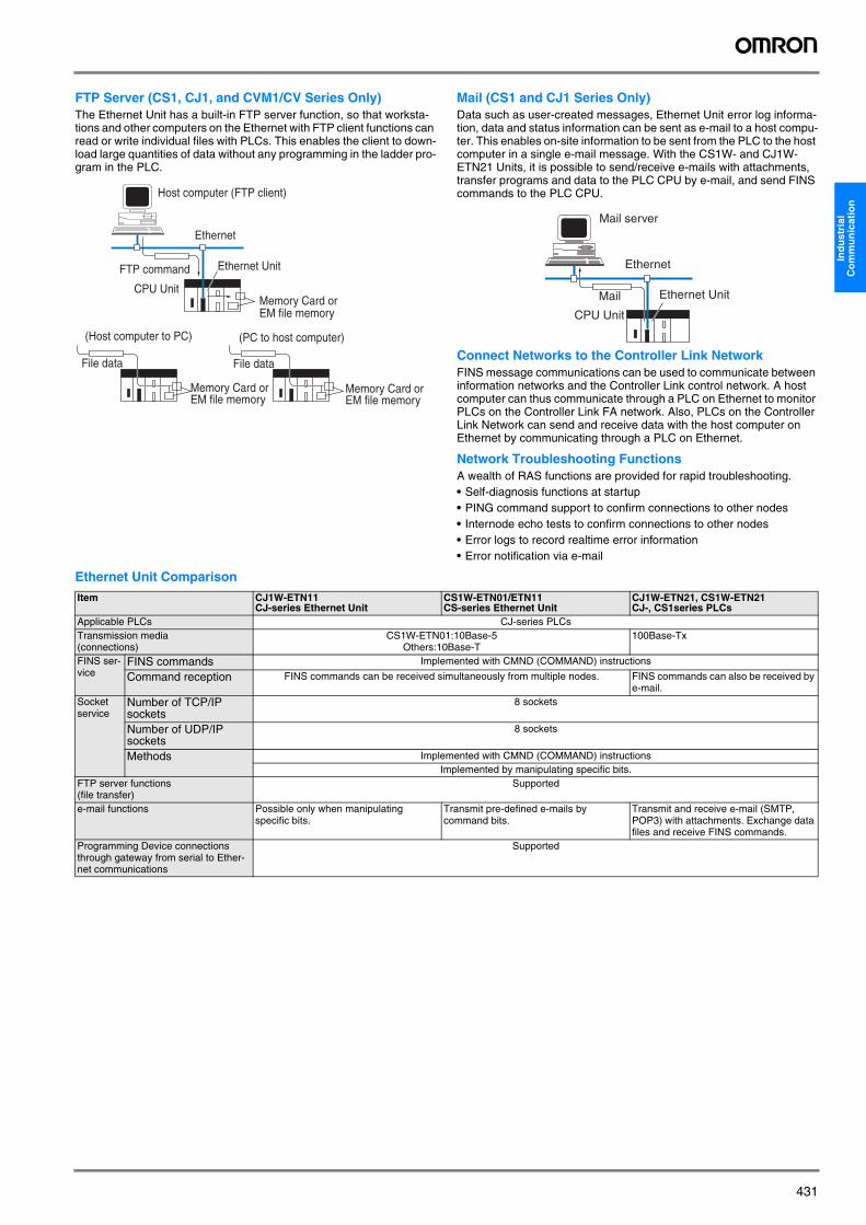
FTP Server (CS1, CJ1, and CVM1/CV Series Only)The Ethernet Unit has a built-in FTP server function, so that worksta-tions and other computers on the Ethernet with FTP client functions can read or write individual files with PLCs. This enables the client to down-load large quantities of data without any programming in the ladder pro-gram in the PLC.
Mail (CS1 and CJ1 Series Only)Data such as user-created messages, Ethernet Unit error log informa-tion, data and status information can be sent as e-mail to a host compu-ter. This enables on-site information to be sent from the PLC to the host computer in a single e-mail message. With the CS1W- and CJ1W-ETN21 Units, it is possible to send/receive e-mails with attachments, transfer programs and data to the PLC CPU by e-mail, and send FINS commands to the PLC CPU.
Connect Networks to the Controller Link NetworkFINS message communications can be used to communicate between information networks and the Controller Link control network. A host computer can thus communicate through a PLC on Ethernet to monitor PLCs on the Controller Link FA network. Also, PLCs on the Controller Link Network can send and receive data with the host computer on Ethernet by communicating through a PLC on Ethernet.
Network Troubleshooting FunctionsA wealth of RAS functions are provided for rapid troubleshooting.• Self-diagnosis functions at startup• PING command support to confirm connections to other nodes• Internode echo tests to confirm connections to other nodes• Error logs to record realtime error information• Error notification via e-mail
Ethernet Unit Comparison
Host computer (FTP client)
Ethernet
FTP command Ethernet Unit
CPU UnitMemory Card or EM file memory
(Host computer to PC) (PC to host computer)
File data File data
Memory Card or EM file memory
Memory Card or EM file memory
Mail server
Ethernet
Ethernet Unit
CPU Unit
Item CJ1W-ETN11 CJ-series Ethernet Unit
CS1W-ETN01/ETN11 CS-series Ethernet Unit
CJ1W-ETN21, CS1W-ETN21CJ-, CS1series PLCs
Applicable PLCs CJ-series PLCsTransmission media (connections)
CS1W-ETN01:10Base-5Others:10Base-T
100Base-Tx
FINS ser-vice
FINS commands Implemented with CMND (COMMAND) instructions
Command reception FINS commands can be received simultaneously from multiple nodes. FINS commands can also be received by e-mail.
Socket service
Number of TCP/IP sockets
8 sockets
Number of UDP/IP sockets
8 sockets
Methods Implemented with CMND (COMMAND) instructionsImplemented by manipulating specific bits.
FTP server functions (file transfer)
Supported
e-mail functions Possible only when manipulating specific bits.
Transmit pre-defined e-mails by command bits.
Transmit and receive e-mail (SMTP, POP3) with attachments. Exchange data files and receive FINS commands.
Programming Device connections through gateway from serial to Ether-net communications
Supported
Y201-EN2-03.book Seite 431 Donnerstag, 13. April 2006 9:40 09
432 Industrial Communication
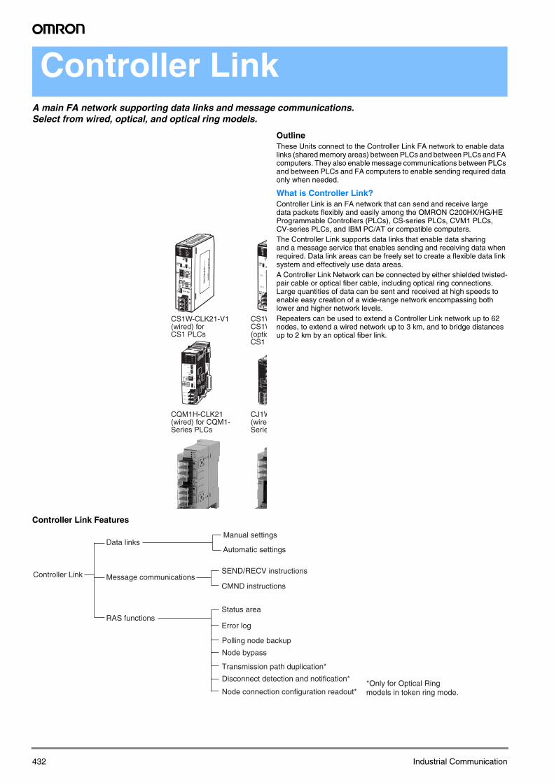
Controller LinkA main FA network supporting data links and message communications. Select from wired, optical, and optical ring models.
OutlineThese Units connect to the Controller Link FA network to enable data links (shared memory areas) between PLCs and between PLCs and FA computers. They also enable message communications between PLCs and between PLCs and FA computers to enable sending required data only when needed.
What is Controller Link?Controller Link is an FA network that can send and receive large data packets flexibly and easily among the OMRON C200HX/HG/HE Programmable Controllers (PLCs), CS-series PLCs, CVM1 PLCs, CV-series PLCs, and IBM PC/AT or compatible computers. The Controller Link supports data links that enable data sharing and a message service that enables sending and receiving data when required. Data link areas can be freely set to create a flexible data link system and effectively use data areas. A Controller Link Network can be connected by either shielded twisted-pair cable or optical fiber cable, including optical ring connections. Large quantities of data can be sent and received at high speeds to enable easy creation of a wide-range network encompassing both lower and higher network levels.Repeaters can be used to extend a Controller Link network up to 62 nodes, to extend a wired network up to 3 km, and to bridge distances up to 2 km by an optical fiber link.
Controller Link Features
CS1W-CLK21-V1 (wired) for CS1 PLCs
CS1WCS1W(opticCS1
CQM1H-CLK21 (wired) for CQM1-Series PLCs
CJ1W(wireSerie
Controller Link
Data links
Message communications
RAS functions
Automatic settings
Manual settings
SEND/RECV instructions
CMND instructions
Status area
Error log
Node bypass
Transmission path duplication*
Disconnect detection and notification*
Node connection configuration readout*
Polling node backup
*Only for Optical Ring models in token ring mode.
Y201-EN2-03.book Seite 432 Donnerstag, 13. April 2006 9:40 09

433
Ind
ust
rial
C
om
mu
nic
atio
n
System Configuration
Wired System (Twisted-pair Cable)Wired Systems are supported by CJ-series, CS-series, C200HX/HG/HE(-Z), CQM1H, CVM1, and CV-series PLCs.
Optical Bus or Optical Ring System (H-PCF or GI Cable)Optical Systems are supported by CS-series, CVM1, and CV-series PLCs.
Token Ring Mode
Token Bus Mode
Features
Data LinksData links allow the constant sharing of data in predetermined data areas between nodes, between PLCs, or between a PLC and an IBM PC/AT or compatible computer on the network. Data links do not require the use of communications programs on the PLC (CPU Unit) or IBM PC/AT or compatible computer. Data written in the send area of the local node will be automatically sent to the receive area of other nodes.The I/O area (CIO area), data link area (LR area), data memory area (DM area), and extended data memory area (EM area) can be freely set in the send or receive area. • Number of send words per node: 1,000 words max.• Number of send and receive words per node:
CS/CJ-series PLCs: 12,000 words max.C200HX/HG/HE(-Z)/CVM1/CV-series PLCs: 8,000 words max.Computer nodes: 32,000 words max.
The data link areas can be set automatically or manually.
Automatic SettingUsed for simple data link processing. Data link can be performed by simply setting parameters in the DM area of the PLC.Various predefined communication modes can be selected (equal size areas, master-slave type, chain link type) using -V1 models.
CS1
CQM1H
POWER
PA205R
DC24VAC240V
OUTPUTRUN
INPUTAC100-240V
L2/N
L1
CONTROLLER
CJ1G-CPU44SYSMAC
PROGRAMMABLEERR/ALM
RUN
COMM
INHPRPHL
OPEN
PERIPHERAL
BUSY
MCPWR
PORT
CJ1W-CLK21 Controller Link Unit
CJ-series PLC
Twisted-pair cable
C200HW-CLK21 Controller Link Unit
C200HX/HG/HEPLC
CQM1H-CLK21 Controller Link Unit
CQM1HPLC
3G8F7-CLK21-E Controller Link PCI Support Board
IBM PC/AT or compatible computer
CS1W-CLK21 Controller Link Unit
CS-series PLC
CS1
CS1
CS1W-CLK12-V1/52-V1 Controller Link Unit (Token ring mode)
CVM1-CLK12/52 Controller Link Unit (Token ring mode)
CS1W-CLK12-V1/52-V1 Controller Link Unit (Token ring mode)
CVM1-CLK12/52 Controller Link Unit (Token ring mode)
CS-series PLC
CVM1 or CV-series PLC
CVM1 or CV-series PLC
CS-series PLC
3G8F7-CLK12/52 Controller Link PCI Support Board (Token ring mode)
H-PCF/GI Optical fiber cable(ring connection)
Backup power supply (24 V DC)
IBM PC/AT or compatible computer
CS1 CS1
CS1W-CLK12-V1/52-V1 Controller Link Unit(Token bus mode)
CS1W-CLK12-V1/52-V1Controller Link Unit
CVM1-CLK12/52 Controller Link Unit(Token bus mode)
CS-series PLC CS-series PLC
CVM1 or CV-series PLC
H-PCF/GI Optical Fiber Cable (daisy-chain connection)
IBM PC/AT or compatible computer
3G8F7-CLK12 Controller LinkPCI Support Board(Token bus mode)
Backup power supply (24 V DC)
Controller Link Unit
Constant data exchange (sharing)(IR/CIO area, Link/LR area, DM area, etc.)
PLC PLC PLC
Y201-EN2-03.book Seite 433 Donnerstag, 13. April 2006 9:40 09

434 Industrial Communication
Manual SettingUsed for flexible data link processing depending on each system.Using the Controller Link Support Software, individual data link tables can be set for each node and the data link area can be freely allocated for each node. Send data size per node can be freely set. It is possible to set nodes for only send or receive data. With the Controller Link Unit, the data link can be set to receive only a part of the data link area of other nodes.
Message ServiceThe message service can be used to control data transmission with particular nodes, reading or writing of status data, changing of opera-tion modes, etc., by executing communications instructions in the user program. The communications instructions include SEND and RECV instructions for data transmission and CMND instructions for sending various commands.
SEND/RECVThe SEND and RECV instructions sends and receives data in an area of a particular node.The SEND instruction sends data from an area of the local node and writes to an area in the designated node.The RECV instruction requests the designated node to send area data and writes the data to the local node.
CMNDThe CMND instruction sends commands such as those to read or write data at other nodes, perform control operations, or read error logs. With the Controller LInk Unit, OMRON’s command protocol called FINS is used.
Twisted-pair Cable or Optical Fiber Cable ConnectionsThe Controller Link Units can be connected to the network using either shielded twisted-pair cable, H-PCF fiber-optic cable, or GI fiber-optic cable. Select the system that suits your application.
Features of Twisted-pair CableTwisted-pair cable is easy to connect and maintain. The cable can be processed much more easily than coaxial or fiber-optic cable, thereby reducing the cost of tools and assembly time.Connections are made to a terminal block on the Controller Link Unit and to a special connector on the Controller Link Support Board for easy system assembly and modification.The network is equipped with the required terminating resistance built into the Units allowing the terminating resistance to be easily set at both ends of the network using a simple switch.
Features of Optical Fiber CableOptical Fiber Cable has superior noise resistance, so this system can provide highly reliable communications even in very noisy conditions. The fiber-optic cable allows long-distance and large-scale networks.With H-PCF fiber-optic cable, the communications distance can be up to 20 km in total, enabling a wider range of system size and network scale.
Compatibility with Different Node ConfigurationsThe following Controller Link Units and Controller Link Boards are available for communications between different models. Wired Units and Optical/Optical Ring Units, however, cannot be combined on the same network.
Wired System• Units for CQM1H, CJ-series, CS-series, C200HX/HG/HE(-Z), and
CVM1/CV-series PLCs and Support Board interfaces for computerswith a PCI bus
Optical Ring System (H-PCF or GI Cable)• Units for CS-series and CVM1/CV-series PLCs and Support Board
interfaces for computers with a PCI bus
Flexible Inter-network ConnectionsThe Controller Link Network can connect to other networks (Ethernet, SYSMAC NET, SYSMAC LINK, and another Controller Link network) via CVM1/CV-series or CS-series PLCs. By installing a Communicati-ons Unit for the Ethernet, SYSMAC NET or SYSMAC LINK on the same CS-series or CV series-PLC as a Controller Link Unit, a message ser-vice can be created with nodes in interconnected networks through the PLC. Communications are possible across up to three network levels.The programming and monitoring of other PLCs on the network can be conducted from Programming Devices connected to the PLC’s CPU Unit. Inter-network connections are possible in this case also and can cover up to three network levels.
RAS FunctionsRAS performs real-time monitoring of the network status. If an error occurs in the network, RAS records and displays the time and contents of the error.
Status Area
Data Link Status AreaWhen the data link function is used, the data link status is reflected in the data link status area of the PLCs.
Network Status Area Other than the Data LinkThe network status such as the state of node participation is reflected in the status area of the PLCs.
Error LogThe error log function records contents (codes) and times of errors that occur in the network into the RAM or EEPROM, up to the maximum of 39 errors.The recorded errors can be read using the Controller Link Support Soft-ware or the message service function.
Node Bypass Data communications can be continued by bypassing the node, even when a node in the communications line malfunctions or the PLC or IBM PC/AT or compatible computer power supply is turned OFF. This prevents the whole network system from being affected by a node mal-function or power interruption.To use the bypass node function, a 24-V DC backup power must be supplied to the Controller Link Unit/Support Board.
Transmission Path DuplicationIn the token-ring mode in an Optical Ring System (H-PCF cable), data transmission will be unaffected even by a cable or connector break at one location in the ring connection. With the fiber-optic cable wired in a ring shape, a break at one point will simply cause the transmission to be routed in the other path.
Disconnect Detection and NotificationEven with transmission path duplication, the network will be broken if disconnections occur in two or more places. In the token-ring mode in an Optical Ring System (H-PCF cable), the location of a disconnection can be detected and can be identified by means of the status display for all nodes. This function can be used to prevent system crashes in advance, by performing maintenance when a disconnection occurs at one place.
Node Connection Configuration Data ReadingIn the token-ring mode in an Optical Ring System (H-PCF cable), con-nection data can be read for all of the nodes configured in the network. The information that can be read includes the order in which the nodes are connected and which of two optical connectors is connected to which node. Special support software (Controller Link Support Soft-
Controller LinkUnit
Part only
Part only
PLC PLC PLC
Controller Link Unit
Data transmission (under certain conditions) as required
Communications instruction (SEND/RECV/CMND)
CS1
Message
SEND
User program
PLC PLC PLC
Y201-EN2-03.book Seite 434 Donnerstag, 13. April 2006 9:40 09

435
Ind
ust
rial
C
om
mu
nic
atio
n
ware, Ver. 2.00 or later) is required in order to read the node connection configuration data.
Data Link Settings with CX-ProgrammerWith the CS-series Controller Link Unit, the CX-Programmer pro-gramming software can be used to set data links freely or monitor data link status. (The Controller Link Support Software cannot be used con-nected directly to the RS-232C port on a CS-series PLC.)
Communications Specifications
Note: 1. Optical Ring Units in token bus mode can be used on the same network as Optical Bus Units/Boards (CS1W-CLK11 and 3G8F5-CLK11).2. With the token-bus method, the maximum number of nodes in an Optical Bus System with optical bus nodes (i.e., model numbers ending
in CLK11) is 32 (node addresses 1 to 32). The total number of words that can be transmitted in a data link is 32,000 words max. CX-Netin CX-Programmer can be used in systems with up to 32 nodes (node addresses 1 to 32). Use Controller Link Support Software (Ver.2.00 or later) for systems with up to 62 nodes (node addresses 1 to 62).
3. For CS1/CSJ. C200HX/HG/HE, CVM1/CV-series, and CQM1H PLCs: 8,000 words.
Data Link Specifications
Items Wired Optical Ring, H-PCF cable (See note 1.)
Optical Ring, GI cable
Baud rate 2 Mbps, 1 Mbps, or 500 kbps 2 Mbps 2 MbpsData Link cycle time (2 kWords + 2 Kbits for 32 nodes)
35 ms (2 bps) 37 ms 37 ms
Maximum transmission distance 500 m, 800 m, 1 km 20 km 30 kmMaximum distance between nodes 500 m, 800 m, 1 km Crimp cut: 800 m
Adhesive: 1 km 62.5/124 μm: 2 km50/125 μm: 1 km
Transmission medium (cable) Shielded twisted-pair cable (special cable)
H-PCF cable (200/230 μm) GI cable (62.5/125 μm or 50/125 μm)
Node connection method Terminal block (M3 crimp terminals) Connected via special 2-carrier optical cable (JIS-F07)
Connected via ST connectors (IEC-874-10)
Transmission path format Multidrop connections (token-bus mode)
Ring method (token-ring mode)Daisy-chain method (token-bus mode)
Ring method (token-ring mode)Daisy-chain method (token-bus mode)
Maximum number of nodes 32 nodes 62 nodes (See note 2.) 62 nodes (See note 2.)Number of network levels 8 (via FINS communications) 8 (via FINS communications) 8 (via FINS communications)Number of data link words
Per network 32,000 words 64,000 words 64,000 wordsPer node Send:1,000 words max.
Receive: 20,000 (See note 3.)(Computer with Support Board: 32,000 words)
Send:1,000 words max.Receive: 20,000 (See note 3.)(Computer with Support Board: 62,000 words)
Send:1,000 words max.Receive: 20,000 (See note 3.)(Computer with Support Board: 62,000 words)
Message length 2,012 bytes max. (including the header)
2,012 bytes max. (including the header)
2,012 bytes max. (including the header)
International standards EC, UL/CSA EC, UL/CSA EC, UL/CSARAS functions Node bypass
Error detectionPolling node backup Self-diagnosis function (hardware checking at startup)Watchdog timerBroadcast test Error log function
Node bypass Error detectionPolling node backup Self-diagnosis function (hardware checking at startup)Watchdog timerBroadcast test Error log functionLoop bypass power supplyLoopback functionality (token ring mode)
Node bypass Error detectionPolling node backup Self-diagnosis function (hardware checking at startup)Watchdog timerBroadcast test Error log functionLoop bypass power supplyLoopback functionality (token ring mode)
Models For PLCs CS1W-CLK21-V1, CJ1W-CLK21-V1, CQM1H-CLK21
CS1W-CLK12-V1 CS1W-CLK52-V1
For computers 3G8F7-CLK21 (PCI bus) 3G8F7-CLK12-V1 (PCI bus) 3G8F7-CLK52-V1 (PCI bus)
Item Automatically set links User-set linksNumber of data link nodes 32 nodes max. (2 nodes min.)Number of data link words
Send/receive words per node (total of areas 1 and 2)
CS/CJ Series: 20,000 words max.CVM1/CV Series, C200HX/HG/HE, CQM1H: 8,000 wordsPersonal computers: 32,000 words
Data link areas Area 1 CIO/IR area (I/O bits, works bits, etc., including data link bits)
CIO/IR area (I/O bits, works bits, etc., including data link bits), DM area, EM area
Area 2 DM area, EM area CIO/IR area (I/O bits, works bits, etc., including data link bits), DM area, EM area
Number of send words per node
Area 1 0 to 1,000 words (same num-ber for each node)
Max. total for area 1 and area 2: 1,000 words
0 to 1,000 words (may be dif-ferent for each node)
Max. total for area 1 and area 2: 1,000 words
Area 2 0 to 1,000 words (same num-ber for each node)
0 to 1,000 words (may be dif-ferent for each node)
Data reception Area 1 All of the data sent by the other nodes is received. It is not possible to receive only part of the data.
Settings can be made to receive all, none, or part of the data from any specific node.Area 2
Offset setting Area 1 Not supported Supported (Settings can be made to receive a specified number of words from a specified word offset from the first word.)
Area 2
Send node order Area 1 The order is the same as the node addresses. Any order The same order must be used for areas 1 and 2.Area 2 Any order
Y201-EN2-03.book Seite 435 Donnerstag, 13. April 2006 9:40 09

436 Industrial Communication
Message Communications Specifications
Conversion guide from SYSMAC LINK to Controller Link
Note: With the token-bus method, the maximum number of nodes in an Optical Bus System with optical bus nodes (i.e., model numbers ending in CLK11) is 32 (node addresses 1 to 32). The total number of words that can be transmitted in a data link is 32,000 words max. CX-Net in CX-Programmer can be used in systems with up to 32 nodes (node addresses 1 to 32). Use Controller Link Support Software (Ver. 2.00 or later) for systems with up to 62 nodes (node addresses 1 to 62).
Item SEND/RECV CMNDApplication Sending and receiving data Reading and writing data at other nodes (e.g., file memo-
ry), changing the operating mode and other control opera-tions, reading error logs, etc.
Message contents Sending commands to send or receive data Sending any FINS commandLocal node to remote node PLC to PLC Supported. Supported.
PLC to computer Supported, but programming is required on the computer to return a response)
Supported, but programming is required on the computer to return a response)
Computer to PLC Supported, but programming is required on the computer to receive a response)
Supported, but programming is required on the computer to receive a response)
Local node: Remote nodes SEND: 1:1 or 1:N (broadcasting)RECV: 1:1
1:1 or 1:N (broadcasting)
Data length 1,980 bytes (990 words) max. 1,990 bytes max.
Item SYSMAC LINK Controller LinkTransmission path Coaxial cable (5C-2V) or optical fiber cable (optical
bus)Twisted-pair cable or optical fiber cable (optical ring or optical bus)
Transmission distance Coaxial cable: 1km max.Optical fiber cable: 10 km max
Twisted-pair cable: 1km max. at 500 kbps, 500 m max. at 2 MbpsOptical fiber cable: 20 km max
Baud rate Coaxial: 2 Mbps (fixed)Optical fiber cable: 2 Mbps (fixed)
Twisted-pair cable: 2 Mbps, 1 Mbps, 500 kpbsOptical fiber cable: 2 Mbps (fixed)
Maximum number of nodes 62 nodes Twisted-pair cable: 32 nodesOptical fiber cable: 62 nodes (See note.)
Data links
Automatically set
No. of send/receive data link words per node
CS Series: 2,966 words max. CS Series: 20,000 words max.CVM1/CV Series, C200HX/HG/HE(-Z), CQM1H: 8,000 words max.
Link areas Area 1 Data Link Area in CIO Ar-ea, fixed first word: CIO 1000 (or LR 00)
Automatic setting in LR area only, DM area only, or both LR and DM areas.
CIO/IR area, user-specified first word
Area 2 DM Area, fixed first word: DM 0000
DM or EM area, user-specified first word
No. of send words per node (same for each node)
4, 8, 16, or 32 words 1 to 1,000 words, user specified
User-set Node order User-setSend size Can be setReceive-only nodes Not supported (Send area size can be set to 0.) SupportedSend-only nodes SupportedData areas Fixed (Area 1: CIO, Area 2: DM) Can be setReceive size All or nothing Can be setReceive offset (from first word) Cannot be set (must receive from beginning) Can be set
Communications cycle time Can be set Cannot be set
Y201-EN2-03.book Seite 436 Donnerstag, 13. April 2006 9:40 09

437
Ind
ust
rial
C
om
mu
nic
atio
n
Serial CommunicationSerial Communications Connections Examples
Serial Communications Support
PLC Unit name Port Serial communications modeProtocol macro
Host Link 1:N NT Link
1:1 NT Link
No-proto-col
1:1 link Peripheral bus Programming Console bus
General purpose
Host com-puter
OMRON PTs
OMRON PTs
General purpose
C-series PLCs
Programming Devices
Programming Console
CS1/CJ1 CPU Unit Peripheral --- Supported Supported --- --- --- Supported SupportedRS-232C --- Supported Supported --- Supported --- Supported ---
C200HX/HG/HE(-Z) Peripheral --- Supported --- --- Supported --- Supported SupportedRS-232C --- Supported Supported Supported Supported Supported --- ---
CVM1/CV Peripheral --- --- --- --- --- --- Supported SupportedRS-232C --- Supported
(DIP switch setting)
--- Supported(DIP switch setting)
--- --- --- ---
CQM1H Peripheral --- Supported --- --- Supported --- Supported SupportedRS-232C --- Supported --- Supported Supported Supported --- ---
CPM2A/ CPM2C Peripheral --- Supported --- --- Supported --- Supported SupportedRS-232C --- Supported Supported
(-V2 only)Supported Supported Supported --- ---
SRM1(-V2) Peripheral --- Supported --- --- Supported --- Supported SupportedRS-232C --- Supported --- Supported Supported Supported --- ---
C200HX/HG/HE(-Z) C200H Communications Board
RS232C, RS422A/485
Supported Supported Supported Supported Supported Supported --- ---
CQM1H CQM1H Serial Communications Board
RS232C, RS422A/485
Supported Supported Supported Supported Supported Supported --- ---
IBM PC/AT or compatible
Programming Devices
PT
MicrocomputerGeneral external devicesGeneral external devices PLC from other company
Protocol macros
Protocol macros
Host Link
Protocol macros
NT Link
Peripheral bus
ASCII Unit Serial Communications Unit Serial Communications BoardCPU Unit
General-purpose protocols written in BASIC in ASCII Unit
(Temperature Controllers, Barcode Readers, etc.)
CX-ProgrammerCX-ProtocolCX-Motion Programming
Console
Y201-EN2-03.book Seite 437 Donnerstag, 13. April 2006 9:40 09

438 Industrial Communication
Protocol MacrosData communications procedures called protocols can be created on the CX-Protocol to match the communications specifications of an external devices with an RS-232C or RS-422A/485 port. (Communica-tions, however, must be half-duplex or full-duplex and use start-stop synchronization.) The protocols are transferred to Serial Communicati-ons Board or Units to then enable data communications with the exter-nal devices merely by executing the PMCR instruction in the CPU Unit.Standard protocols for OMRON components (Temperature Controllers, Panel Meters, Bar Code Readers, Modems, etc.) are provided as a standard feature. The standard protocols can be modified according to application needs and easily used.
Host LinksC-mode (Host Link) commands or FINS command wrapped in Host Link headers and terminators can be sent from a host computer (e.g., a personal computer or PT) to perform many operations, such as rea-ding and writing I/O memory or controlling the operating mode of the PLC.Unsolicited commands can be sent from the PLCs to the host compu-ters. FINS commands are wrapped in Host Link headers and termina-tors automatically when SEND, RECV, or CMND instructions are executed.
1:N NT LinksA PLC can be linked to PTs (Programmable Terminals) from an RS-232C or RS-422A/485 port so that I/O memory in the PLC can be allo-cated for PT control areas, PT status areas, and objects, such as touch switches, lamps, and memory tables. One PLC can be linked to from 1 to 8 PTs.
Note: 1. There are two types of NT Links: 1:1 and 1:N. These are com-pletely different communications modes and are not compat-ible with each other. Always set the PT for the 1:N mode.Communications will not be possible if it is set to 1:1.
2. The NT-AL001 Adapter Unit is required to connect the RS-232C port on the NT30/NT30C PTs in a 1:N NT Link.
3. The PT’s Programming Console functionality is not supportedwith 1:N NT Links.
Protocol Macro Features
Support a Wide-range of ProtocolsWith both RS-232C and RS-422A/485 ports, essentially any device that supports full or half duplex communications and start-stop synchroniza-tion can be connected. Send and receive frames can be created as required to meet communications frame specifications, Essentially all send frames (e.g., command + data) and expected receive frames (e.g., responses) can be matched to the communications frames (mes-sages) of the external device.
Use Processing Functions for CommunicationsError check code calculations, send frame length calculations, and numeric conversions between ASCII and hexadecimal are all suppor-ted.
Monitor Communications TimeResponse wait monitoring, response completion monitoring, and send completion monitoring are all supported, and ending or retrying com-munications can be set for when monitor times are exceeded.
Retry ProcessingJust set the number of retries to execute retry processing when some-thing happens to cause an error.
Include PLC Read/Write Variables in Send and Receive (Expected) FramesRead/write variables for I/O memory in the PLC can be included in the send frames (messages). PLC data will be read when sending and used as the destination address or data. Read/write variables for I/O memory in the PLC can also be included in the receive frames. PLC data will be written as the source address or data when response is received.
Repeat Variables to Switch Write Destinations for 1:N CommunicationsRepeat counters for send/receive processing can be included in varia-bles so that, for example, the same data can be sent to up to 32 diffe-rent destinations by switching the destination address. (The limit of 32 is imposed by the physical layer.) When receiving data, the write address can be easily switched when receiving data for I/O memory in the PLC.
PLC Interrupt Processing at Data ReceptionInterrupts to the PLC’s CPU Unit can be generated when data is recei-ved to execute an interrupt program. (Interrupts are supported only by Serial Communications Boards, and not by Serial Communications Units.)
Next Processing Switches in Receive DataThe received data can be compared to up two 15 expected reception messages that have been registered in advance and the results of com-parison can be used to switch the next process to be executed.
C200H, C200HS, C200HX/HG/HE(-Z)
Host Link Unit RS232C, RS422A/485
--- Supported --- --- --- --- --- ---
CS1 Serial Communications Board
RS232C, RS422A/485
Supported Supported Supported --- Supported --- --- ---
Serial Communications Unit
RS232C Supported Supported Supported --- Supported --- --- ---
CJ1 Serial Communications Unit
RS232C, RS422A/485
Supported Supported Supported --- Supported --- --- ---
PLC Unit name Port Serial communications modeProtocol macro
Host Link 1:N NT Link
1:1 NT Link
No-proto-col
1:1 link Peripheral bus Programming Console bus
General purpose
Host com-puter
OMRON PTs
OMRON PTs
General purpose
C-series PLCs
Programming Devices
Programming Console
Message
General-purpose external device
Response (unsolicited)
C-mode (Host Link) command or FINS command
Response
PT PT
Y201-EN2-03.book Seite 438 Donnerstag, 13. April 2006 9:40 09
439
Ind
ust
rial
C
om
mu
nic
atio
n
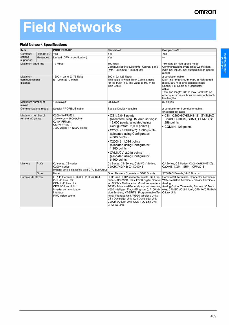
Field NetworksField Network Specifications
Item PROFIBUS-DP DeviceNet CompoBus/SCommuni-cations supported
Remote I/O Yes Yes YesMessages Limited (DPV1 specification) Yes ---
Maximum baud rate 12 Mbps 500 kpbsCommunications cycle time: Approx. 5 ms (with 128 inputs, 128 outputs)
750 kbps (in high-speed mode)Communications cycle time: 0.8 ms max. (with 128 inputs, 128 outputs in high-speed mode)
Maximum communications distance
1200 m up to 93.75 kbit/sto 100 m at 12 Mbps
500 m (at 125 kbps)This value is when Thick Cable is used for the trunk line. The value is 100 m for Thin Cable.
2-conductor cableMain line length:100 m max. in high-speed mode, 500 m in long-distance modeSpecial Flat Cable or 4-conductor cable:Total line length: 200 m max. total with no other specific restrictions for main or branch line lengths
Maximum number of slaves
125 slaves 63 slaves 32 slaves
Communications media Special PROFIBUS cable Special DeviceNet cable 2-conductor or 4-conductor cable, or special flat cable
Maximum number of remote I/O points
C200HW-PRM21:300 words = 4800 pointsCJ1W-PRM21, CS1W-PRM21:7000 words = 112000 points
• CS1: 2,048 points(Allocated using DM area settings: 16,000 points, allocated using Configurator: 32,000 points.)
• C200HX/HG/HE(-Z): 1,600 points(allocated using Configurator: 4,800 points.)
• C200HS: 1,024 points(allocated using Configurator: 1,280 points.)
• CVM1/CV: 2,048 points(allocated using Configurator: 6,400 points.)
• CS1, C200HX/HG/HE(-Z), SYSMAC Board, C200HS, SRM1, CPM2C-S: 256 points
• CQM1H: 128 points
Masters PLCs CJ series, CS series, C200H series(Master Unit is classified as a CPU Bus Unit.)
CJ Series, CS Series, CVM1/CV Series, C200HX/HG/HE(-Z), C200HS
CJ Series, CS Series, C200HX/HG/HE(-Z), C200HS, CQM1, SRM1, CPM2C-S
Other None Open Network Controllers, VME Boards SYSMAC Boards, VME BoardsRemote I/O slaves GT1 I/O terminals, C200H I/O Link Unit,
CJ1 I/O Link Unit, CQM1 I/O Link Unit, CPM I/O Link Unit, Inverter communication interface, F150 vision sytem
DRT1 and DRT2 sensor terminals, GT1 ter-minals, RS-232C Units, E5EK Digital Control-ler, 3G3MV Multifunction Miniature Inverters, 3G3FV Advanced General-purpose Inverters, V600 Intelligent Flags (ID system), F150 Vi-sion Sensors, NT-DRT21 Programmable Ter-minal Interface Unit, WD30 Wireless Units, CS1 DeviceNet Unit, CJ1 DeviceNet Unit, C200H I/O Link Unit, CQM1 I/O Link Unit, CPM I/O Link
Remote I/O Terminals, Connector Terminals, Water-resistive Terminals, Sensor Terminals, Analog Analog Output Terminals, Remote I/O Mod-ules, CPM2C I/O Link Unit, CPM1A/CPM2A I/O Link Unit
Y201-EN2-03.book Seite 439 Donnerstag, 13. April 2006 9:40 09

440 Industrial Communication
PROFIBUS-DP
PROFIBUS-DP introductionPROFIBUS is a vendor-independent, open fieldbus standard for a wide range of applications in manufacturing-, process- and building automation. The PROFIBUS standards are set and maintained by the PROFIBUS Nutzer Organisation (PNO) since 1990. Over the years PROFIBUS has become one of the most favoured industry standards for accomplishing a wide variety of process automation tasks. The importance of this common ground for engineers and process automation specialists was immediately recognised by the OMRON company. OMRON became a member of PNO in 1991. Vendor inde-pendence and openness are guaranteed by the PROFIBUS standard IEC 61158 Type 3. With PROFIBUS, devices of different manufacturers can communicate without special interface adjustments. DP stands for Decentralised Peripherals. It is optimised for high speed and low-cost interfacing, especially designed for communication between automation control systems and distributed I/O at the device level.
Protocol architectureThe PROFIBUS protocol architecture is oriented on the Open System Interconnection (OSI) reference model in accordance with the interna-tional standard ISO 7498. PROFIBUS-DP uses layers 1 and 2, and the user interface. Layers 3 to 7 are not defined.Layer 1 (physical layer) defines the physical transmission characteri-stics.Layer 2 (data link layer) defines the bus access control. This streamlined architecture ensures fast and efficient data transmis-sion. The application functions which are availible to the user, as well as the system and device behaviour of the various PROFIBUS-DP device-types are specified in the user interface.
Transmission mediumRS-485 transmission technology or fibre optics are defined as trans-mission media. RS-485 transmission is the most frequently used trans-mission technology. Its application includes all areas in which high transmission speed and simple inexpensive installation are required. Twisted pair shielded copper cable with one conductor pair is used.
Easy installationThe RS-485 transmission technology is very easy to handle. Installa-tion of the twisted pair cable does not require expert knowledge. The bus structure permits addition and removal of stations or step-by-step commissioning of the system without influencing the other stations. Later expansions have no effect on stations which are already in ope-ration.Various transmission speeds between 9.6 kbit/s and 12 Mbit/s can be selected. One unique transmission speed is selected for all devices on the bus when the system is commissioned.
Cable lengthThe maximum cable length depends on the transmission speed. The specified cable lengths are based on type-A cable. The length can be increased by the use of repeaters. The use of more than 3 repeaters in series is not recommended.
Y201-EN2-03.book Seite 440 Donnerstag, 13. April 2006 9:40 09

441
Ind
ust
rial
C
om
mu
nic
atio
n
Product Appearance Model Specifications PagePLC masters CS1W-PRM21 - PROFIBUS-DP master class
one with support of DP-V1 data types- 7k word I/O- Simple configuration- Handles data independently,
thus reduces CPU load
361
CJ1W-PRM21 - PROFIBUS-DP master class one with support of DP-V1 data types
- 7k word I/O- Simple configuration- Handles data independently,
thus reduces CPU load
236
Configurator CX-PROFIBUS Advanced configuration tool that uses FDT/DTM (Field Device Tool and Device Type Manager) Technology- The PROFIBUS-DP network topology and
system characteristics are defined and then downloaded in the OMRON PROFIBUSMaster Unit
- Configuration can be done remotely, via other networks as Ethernet or ControllerLink
647
PLC slave units CJ1W-PRT21 PROFIBUS-DP I/O Link- Data link to any PLC data area- Simple configuration using - Max. data input 100 words- Max. data output 100 words
237
C200HW-PRT21 Can be used on C200HS/HE/HG/HX and CS1G/H- Default 2 words in + 2 words out,
maximum 100 words in and 100 words out
- Simple PROFIBUS-DP node address setting by rotary switches
- Supports SYNC/FREEZE and Fail/Safe functions
362
CQM1-PRT21 - Auto-detects all PROFIBUS-DP baudrates from 9.6 kbits/s to 12 Mbits/s
- Support and indication of PROFIBUS-DP broadcast functions (Sync/Freeze/Clear)
- Communication status available externally via relay output
- Configurable for 2, 4, 6 or 8 words
For more information please con-tact your local OMRON representa-tive
CPM1A-PRT21 PROFIBUS I/O link for CPM1A/CPM2A- LED status display - Max. data input 16 bits and
16 output bits
74
Inverter PROFIBUS Option SI-P1 PROFIBUS-DP slave for E7(PV), F7(RV), G5(FV) Inverters
For more information please con-tact your local OMRON representa-tive
SI-P1/V7 PROFIBUS-DP slave for 3G3MV Inverters For more information please con-tact your local OMRON representa-tive
Servo Drive PROFIBUS Option
JUSP-NS500 PROFIBUS option unit for Sigma-II (W-Series) Servo Drives
For more information please con-tact your local OMRON representa-tive
Y201-EN2-03.book Seite 441 Donnerstag, 13. April 2006 9:40 09

442 Industrial Communication
XtraDrive with PROFIBUS XD-@@-@@DO Intelligent Servo Drive with Embedded PROFIBUS
For more information please con-tact your local OMRON representa-tive
F150 Vision system F150-C15E-3-PRT Number of connected camers: 1 unit / 2 units (using the F150-A20)Processing resolution: 512 (H) x 484 (V)Number of scenes:16 scenes (can be saved to a computer through the RS-232C)Image memory function:Up to 23 scdreebs can be saved)Processing method:Dark-light/2-value method
For more information please con-tact your local OMRON representa-tive
Temperature Controllers E5ZN A dedicated gateway is available. For more information please con-tact your local OMRON representa-tive
PROFIBUS Gateway PRT-SCU11 PROFIBUS-DP Gateway to HostLink and Compoway-Ffor MCW151-Efor E5@N, E5@R, E5@K
Product Appearance Model Specifications Page
Y201-EN2-03.book Seite 442 Donnerstag, 13. April 2006 9:40 09

443
Ind
ust
rial
C
om
mu
nic
atio
n
DeviceNet
DeviceNet: Optimising industrial networkingDeviceNet is an innovative industrial network system that enables a wide range of devices to be easily networked and managed remotely. Everything - from PLCs and remote I/O, to fibre optic sensors, vision systems controllers, servos and inverters - can be seamlessly integra-ted into DeviceNet, making it one of the best industrial field busses around. As a founding member of ODVA, Omron is one of the compa-nies that integrates DeviceNet interfaces into its many core products.
All of Omron’s products are optimised for seamless integration into a DeviceNet system. You can configure Omron’s devices over the network on-the-fly, and add a device or machine to a production line without powering down. DeviceNet is a flexible network, designed to accommodate your growing needs.
Easy to use softwareOmron’s DeviceNet configuration software is specially developed to integrate products in a more user-friendly way than in other bus systems. Omron’s DeviceNet units have a default mode that enables you to set the addresses, plug the products in and watch everything run. The configuration software allows you to monitor and fine-tune the DeviceNet products in your network for optimum operation. The products are literally plug-and-play, and the software is drag-and-drop.Nothing could be easier.
ODVA and Omron –setting the standards DeviceNet is based on open standards and specifications defined by the Open DeviceNet Vendors Association (ODVA), a consortium whose main task is to promote DeviceNetworld-wide. Omron is a founding member of ODVA and a leading player in promoting DeviceNet, and is dedicated to producing and improving products that work with DeviceNet. All Omron products are ODVA certified, making them fully DeviceNet compatible. Thanks to ODVA’s strong conformance testing policies, DeviceNet also ensures the interchangeability and interoperability of control devices from hundreds of manufacturers world-wide.
Overview of DeviceNetTwo types of communications are supported: 1) Remote I/O communications that automatically transfer I/O between slaves and the CPU Unit to which a DeviceNet Unit is mounted without any special programming in the CPU Unit.2) Message communications that read/write messages, control opera-tion, or perform other functions for other CPU Units to which a Device-Net Unit is mounted and slaves. Message communications are achieved by executing specific instructions (CMND) from the program in the CPU Unit to which the DeviceNet Unit is mounted.
The following functions are supported by a CS/CJ-series DeviceNet Unit.• I/O area words can be flexibly allocated for remote I/O Master and
Slave communication. • Multiple DeviceNet Units can be mounted on a single PLC. Fixed
(automatic) allocations are possible for up to three DeviceNet Units.• More than one DeviceNet master unit can be connected to a single
network. With the DeviceNet Configurator, remote I/O can be allo-cated in any order, i.e., not necessarily in the order of nodeaddresses.
Note: When the DeviceNet configurator is connected through a dedi-cated Board or Card it uses one node address in the DeviceNet network. It does not use a node address if it is connected throuogh the serial port of the PLC.
A CS/CJ-series DeviceNet Unit can function as either a master or slave in remote I/O communication. Both can be used simultaneously.With a CS/CJ-series DeviceNet Unit, the DeviceNet network can be treated exactly like a Controller Link, Ethernet, or other network for message communications or remote programming and monitoring by a CX-Programmer.
Y201-EN2-03.book Seite 443 Donnerstag, 13. April 2006 9:40 09
444 Industrial Communication
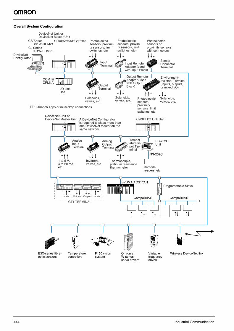
Overall System Configuration
:
Photoelectricsensors, proximity sensors, limitswitches, etc.
Solenoids,valves, etc.
Environment-resistant Terminal(Inputs, outputs,or mixed I/O)
Analog InputTerminal
Analog OutputTerminal
DeviceNet Unit or DeviceNet Master Unit
Inputs Outputs Outputs
GT1 TERMINAL
Temper-ature In-put Ter-minal
Thermocouple,platinum resistancethermometer
RS-232C Unit
Barcode readers, etc.
Inverters,valves, etc.
1 to 5 V, 4 to 20 mA,etc.
A DeviceNet Configuratoris required to place more thanone DeviceNet master on thesame network.
Inputs
RS-232C
SYSMAC CS1/CJ1
CompoBus/S CompoBus/S
Programmable Slave
C200H I/O Link Unit
E3X-series fibre-optic sensors
Temperaturecontrollers
F150 vision system
Omron's W-seriesservo drivers
Variable frequency drives
Wireless DeviceNet link
Photoelectricsensors, proximi-ty sensors, limitswitches, etc.
Photoelectricsensors or proximity sensorswith connectors
Photoelectricsensors, proximi-ty sensors, limitswitches, etc.
I/O Link Unit
CQM1HCPM1A
Solenoids,valves, etc.
Solenoids,valves, etc.
Output Terminal
Output Remote Adapter (used with Output Block)
Input Terminal
Sensor ConnectorTerminal
T-branch Taps or multi-drop connections
DeviceNet Unit or DeviceNet Master Unit
CS Series CS1W-DRM21
C200HZ/HX/HG/E/HS:
CJ Series CJ1W-DRM21
Input Remote Adapter (used with Input Block)
DeviceNet Configurator
Y201-EN2-03.book Seite 444 Donnerstag, 13. April 2006 9:40 09

445
Ind
ust
rial
C
om
mu
nic
atio
n
System Configuration Examples
I/O Terminals Connected as Slaves Other PLCs Connected as Slaves
Masters
Remote I/O Master Functions
Remote I/O Slave (only Units Mounted in a PLC)
DeviceNet500 kbps: 100m125 kbps: 500m
DeviceNetMaster Unit
Slaves
63 slaves
DeviceNet
DeviceNetMaster Unit
C200HX/HG/HE(-Z)or CS-series PLC CQM1H
C200H I/O Link UnitCQM1 I/O Link Unit Programmable
Slave
PLC Model Mountable position Master/Slave function
Maximum number of mountable unitsWith Configurator Without Configurator
CJ Series CJ1W-DRM21 DeviceNet Unit CPU or Expansion CPU Rack (Classified as CPU Bus Units)
Master and Slave
3 16CS Series CS1W-DRM21 DeviceNet UnitCS Series C200HW-DRM21-V1
DeviceNet Master UnitCPU Rack or Expansion I/O Rack (Classified as Special I/O Units)
Master only 16 1C200HX/HG/HE 10 or 16C200HS 10
Item Master Model Without Configurator With ConfiguratorMax. No. of Slave nodes per Master
CJ Series CJ1W-DRM21 63 nodesCS Series CS1W-DRM21CS Series, C200HX/HG/HE C200HW-DRM21-V1 50 nodes 63 nodesC200HS 32 nodes 63 nodes
Max. No. of control points per Master
CJ Series CJ1W-DRM21 2,048 pts (64 input /64 output words) or 16,000 pts (500 input/500 output words)
32,000 pts (500 words x 4 blocks)CS Series CS1W-DRM21CS Series, C200HX/HG/HE C200HW-DRM21-V1 1,600 pts (50 input/50 output words) Without messages: 4,800 pts
With messages: 1,600 ptsC200HS 1,024 pts (32 input/32 output words) 1,280
Max. No. of I/O points per Slave controllable by Master
CJ Series CJ1W-DRM21 100 input/100 output wordsCS Series CS1W-DRM21CS Series, C200HX/HG/HE C200HW-DRM21-V1 32 input/32 output wordsC200HS
Remote I/O allocation areas
CJ Series CJ1W-DRM21 DeviceNet Area in CIO Area, and user-allo-cated words in CIO Area, DM Area, and other areas.
User-allocated words in CIO Area, DM Area, and other areas.
CS Series CS1W-DRM21CS Series, C200HX/HG/HE C200HW-DRM21-V1 DeviceNet Area
C200H DeviceNet words in CIO Area (in-cluding dedicated words/ bits)
User-allocated words in CIO Area, DM Area, and other areas.C200HS
Item CPU Unit to which a Slave is mounted
Unit Model Without the Configurator With the Configurator
Max. No. of I/O pts per Slave
CJ Series CJ1W-DRM21 32 pts (1 input/ 1 output word) or 3,200 pts (100 input/100 output words)
4,800 pts (100 input words x 2/100 output words x 1)CS Series CS1W-DRM21
CS Series, C200HX/HG/HE C200HW-DRT21 1,024 pts (32 input/32 output words)CQM1H, CQM1 Series CQM1-DRT21 32 pts (1 input/1 output word)
Allocation areas in the CPU Unit to which this Slave is mounted
CJ Series CJ1W-DRM21 CIO, WR, DM, EM, HRCS Series CS1W-DRM21CS Series, C200HX/HG/HE C200HW-DRT21 CIO, DM, EM, AR, LR, T/CCQM1H, CQM1 Series CQM1-DRT21 CIO
Y201-EN2-03.book Seite 445 Donnerstag, 13. April 2006 9:40 09

446 Industrial Communication
Message Communications
Master Unit model Send Receive FINS commandsCJ Series CJ1W-DRM21 SEND RECV CMNDCS Series CS1W-DRM21CS Series, C200HX/HG/HE C200HW-DRM21-V1 None None IOWRC200HS Not supported
Item Master model Model CapacityMax. No. of nodes per Master for message com-munications using FINS commands
CJ Series CJ1W-DRM21 63 nodes CS Series CS1W-DRM21CS Series, C200HX/HG/HE C200HW-DRM21-V1 8 nodesC200HS Not supported
Max. No. of nodes per Master for message com-munications using explicit messages
CJ Series CJ1W-DRM21 63 nodesCS Series CS1W-DRM21CS Series, C200HX/HG/HE C200HW-DRM21-V1 63 nodesC200HS Not supported
Max. message length CJ Series CJ1W-DRM21 SEND:267 wordsRECV:269 wordsCMND:542 bytes (starting with command code)
CS Series CS1W-DRM21
CS Series, C200HX/HG/HE C200HW-DRM21-V1 IOWR: 160 bytes (starting with command code)
Y201-EN2-03.book Seite 446 Donnerstag, 13. April 2006 9:40 09
447
Ind
ust
rial
C
om
mu
nic
atio
n
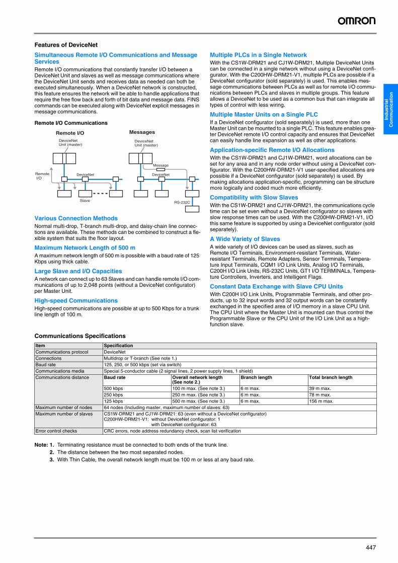
Features of DeviceNet
Simultaneous Remote I/O Communications and Message ServicesRemote I/O communications that constantly transfer I/O between a DeviceNet Unit and slaves as well as message communications where the DeviceNet Unit sends and receives data as needed can both be executed simultaneously. When a DeviceNet network is constructed, this feature ensures the network will be able to handle applications that require the free flow back and forth of bit data and message data. FINS commands can be executed along with DeviceNet explicit messages in message communications.
Remote I/O Communications
Various Connection MethodsNormal multi-drop, T-branch multi-drop, and daisy-chain line connec-tions are available. These methods can be combined to construct a fle-xible system that suits the floor layout.
Maximum Network Length of 500 mA maximum network length of 500 m is possible with a baud rate of 125 Kbps using thick cable.
Large Slave and I/O CapacitiesA network can connect up to 63 Slaves and can handle remote I/O com-munications of up to 2,048 points (without a DeviceNet configurator) per Master Unit.
High-speed CommunicationsHigh-speed communications are possible at up to 500 Kbps for a trunk line length of 100 m.
Multiple PLCs in a Single NetworkWith the CS1W-DRM21 and CJ1W-DRM21, Multiple DeviceNet Units can be connected in a single network without using a DeviceNet confi-gurator. With the C200HW-DRM21-V1, multiple PLCs are possible if a DeviceNet configurator (sold separately) is used. This enables mes-sage communications between PLCs as well as for remote I/O commu-nications between PLCs and slaves in multiple groups. This feature allows a DeviceNet to be used as a common bus that can integrate all types of control with less wiring.
Multiple Master Units on a Single PLCIf a DeviceNet configurator (sold separately) is used, more than one Master Unit can be mounted to a single PLC. This feature enables grea-ter DeviceNet remote I/O control capacity and ensures that DeviceNet can easily handle line expansion as well as other applications.
Application-specific Remote I/O AllocationsWith the CS1W-DRM21 and CJ1W-DRM21, word allocations can be set for any area and in any node order without using a DeviceNet con-figurator. With the C200HW-DRM21-V1 user-specified allocations are possible if a DeviceNet configurator (sold separately) is used. By making allocations application-specific, programming can be structure more logically and coded much more efficiently.
Compatibility with Slow SlavesWith the CS1W-DRM21 and CJ1W-DRM21, the communications cycle time can be set even without a DeviceNet configurator so slaves with slow response times can be used. With the C200HW-DRM21-V1, I/O this same feature is supported by using a DeviceNet configurator (sold separately).
A Wide Variety of SlavesA wide variety of I/O devices can be used as slaves, such as Remote I/O Terminals, Environment-resistant Terminals, Water-resistant Terminals, Remote Adapters, Sensor Terminals, Tempera-ture Input Terminals, CQM1 I/O Link Units, Analog I/O Terminals, C200H I/O Link Units, RS-232C Units, GT1 I/O TERMINALs, Tempera-ture Controllers, Inverters, and Intelligent Flags.
Constant Data Exchange with Slave CPU UnitsWith C200H I/O Link Units, Programmable Terminals, and other pro-ducts, up to 32 input words and 32 output words can be constantly exchanged in the specified area of I/O memory in a slave CPU Unit. The CPU Unit where the Master Unit is mounted can thus control the Programmable Slave or the CPU Unit of the I/O Link Unit as a high-function slave.
Communications Specifications
Note: 1. Terminating resistance must be connected to both ends of the trunk line.2. The distance between the two most separated nodes.3. With Thin Cable, the overall network length must be 100 m or less at any baud rate.
Message
RS-232C
DeviceNetDeviceNet
Slave
DeviceNet Unit (master)
DeviceNet Unit (master)
Remote I/O
Remote I/O Messages
Item SpecificationCommunications protocol DeviceNetConnections Multidrop or T-branch (See note 1.)Baud rate 125, 250, or 500 kbps (set via switch)Communications media Special 5-conductor cable (2 signal lines, 2 power supply lines, 1 shield)Communications distance Baud rate Overall network length
(See note 2.)Branch length Total branch length
500 kbps 100 m max. (See note 3.) 6 m max. 39 m max.250 kbps 250 m max. (See note 3.) 6 m max. 78 m max.125 kbps 500 m max. (See note 3.) 6 m max. 156 m max.
Maximum number of nodes 64 nodes (Including master, maximum number of slaves: 63)Maximum number of slaves CS1W-DRM21 and CJ1W-DRM21: 63 (even without a DeviceNet configurator)
C200HW-DRM21-V1: without DeviceNet configurator: 1with DeviceNet configurator: 63
Error control checks CRC errors, node address redundancy check, scan list verification
Y201-EN2-03.book Seite 447 Donnerstag, 13. April 2006 9:40 09
448 Industrial Communication
DeviceNet product overviewMasters . . . . . . . . . . . . . . . . . . . . . . . . . . . . . . . . . . . . . . . . . . . . . . . . . . . . . . . 449
Configurator . . . . . . . . . . . . . . . . . . . . . . . . . . . . . . . . . . . . . . . . . . . . . . . . . . . 449
Software . . . . . . . . . . . . . . . . . . . . . . . . . . . . . . . . . . . . . . . . . . . . . . . . . . . . . . 449
Slaves . . . . . . . . . . . . . . . . . . . . . . . . . . . . . . . . . . . . . . . . . . . . . . . . . . . . . . . . 450• Smart Slaves . . . . . . . . . . . . . . . . . . . . . . . . . . . . . . . . . . . . . . . . . . . . . . . . . . . . . . . . . . . . . 450
• General-purpose Slaves, DR1 Series . . . . . . . . . . . . . . . . . . . . . . . . . . . . . . . . . . . . . . . . . 451
• Intelligent Slaves Operating as PLC Units . . . . . . . . . . . . . . . . . . . . . . . . . . . . . . . . . . . . . 452
• Other Intelligent Slaves . . . . . . . . . . . . . . . . . . . . . . . . . . . . . . . . . . . . . . . . . . . . . . . . . . . . 453
• The abbreviations used in the “Standards” column in the followingtables indicate the following international standards.U: UL, C:CSA, UC: cULus, CU: cUL, N: NK, L: Lloyd, CE: EC Direc-tivesSee OMRON sales representatives for conditions under which UL,CSA, cULus, cUL, NK, LLOYD, and CE standards were met. Theinformation on standards is current as of August 2002.
EC DirectivesThe EC Directives applicable to PLCs include the EMC Directives and the Low Voltage Directive. OMRON complies with these directives as described below.
EMC Directives
Applicable Standards
EMI:EN50081-2EMS:EN61131-2 and EN61000-6-2 (See note.)PLCs are electrical devices that are incorporated in machines and manufacturing installations. OMRON PLCs conform to the related EMC standards so that the devices and machines into which they are built can more easily conform to EMC standards. The actual PLCs have been checked for conformity to EMC standards. Whether these stan-dards are satisfied for the actual system, however, must be checked by the customer.
EMC-related performance will vary depending on the configuration, wiring, and other conditions of the equipment or control panel in which the PLC is installed. The customer must, therefore, perform final checks to confirm that the overall machine or device conforms to EMC standards.Note: The applicable EMI standard depends on the product.
Low Voltage Directive
Applicable Standard
EN61131-2Devices that operate at voltages from 50 to 1,000 V AC or 75 to 150 V DC must satisfy the appropriate safety requirements. With PLCs, this applies to Power Supply Units and I/O Units that operate in these voltage ranges.These Units have been designed to conform to EN61131-2, which is the applicable standard for PLCs.
International Standards and EC Directives
Y201-EN2-03.book Seite 448 Donnerstag, 13. April 2006 9:40 09
449
Ind
ust
rial
C
om
mu
nic
atio
n
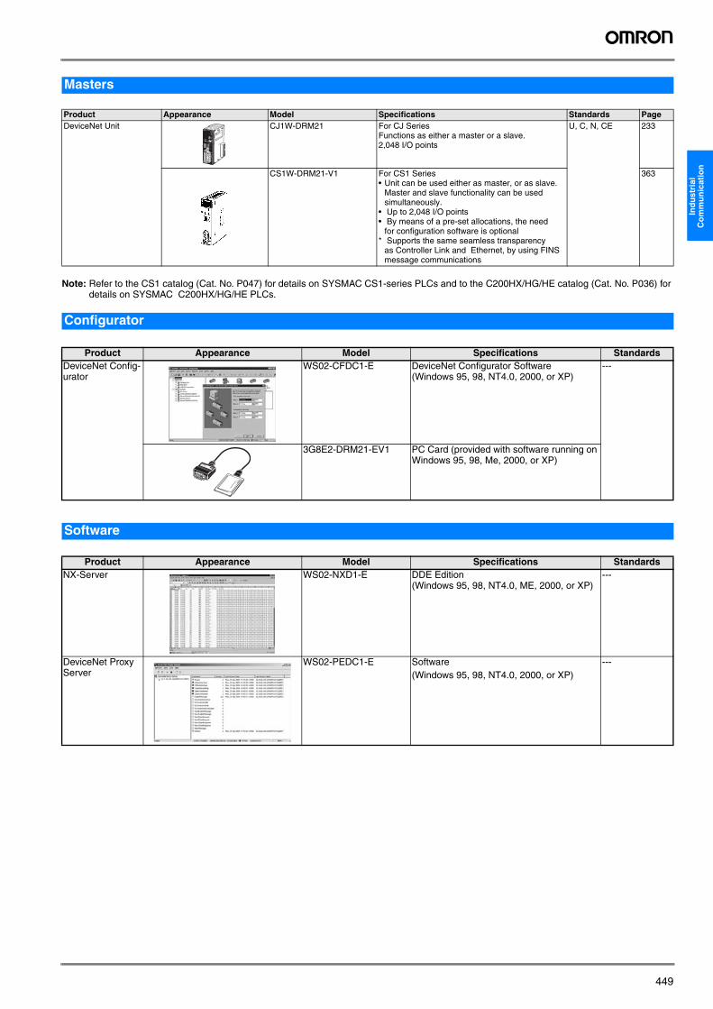
Note: Refer to the CS1 catalog (Cat. No. P047) for details on SYSMAC CS1-series PLCs and to the C200HX/HG/HE catalog (Cat. No. P036) for details on SYSMAC C200HX/HG/HE PLCs.
Masters
Product Appearance Model Specifications Standards PageDeviceNet Unit CJ1W-DRM21 For CJ Series
Functions as either a master or a slave.2,048 I/O points
U, C, N, CE 233
CS1W-DRM21-V1 For CS1 Series• Unit can be used either as master, or as slave.
Master and slave functionality can be used simultaneously.
• Up to 2,048 I/O points• By means of a pre-set allocations, the need
for configuration software is optional* Supports the same seamless transparency
as Controller Link and Ethernet, by using FINS message communications
363
Configurator
Product Appearance Model Specifications StandardsDeviceNet Config-urator
WS02-CFDC1-E DeviceNet Configurator Software(Windows 95, 98, NT4.0, 2000, or XP)
---
3G8E2-DRM21-EV1 PC Card (provided with software running on Windows 95, 98, Me, 2000, or XP)
Software
Product Appearance Model Specifications StandardsNX-Server WS02-NXD1-E DDE Edition
(Windows 95, 98, NT4.0, ME, 2000, or XP)---
DeviceNet Proxy Server
WS02-PEDC1-E Software(Windows 95, 98, NT4.0, 2000, or XP)
---
Y201-EN2-03.book Seite 449 Donnerstag, 13. April 2006 9:40 09
450 Industrial Communication
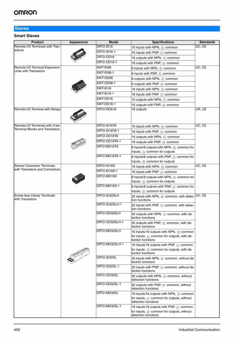
Smart Slaves
Slaves
Product Appearance Model Specifications StandardsRemote I/O Terminals with Tran-sistors
DRT2-ID16 16 inputs with NPN, common UC, CE
DRT2-ID16-1 16 inputs with PNP, commonDRT2-OD16 16 outputs with NPN, commonDRT2-OD16-1 16 outputs with PNP, common
Remote I/O Terminal Expansion Units with Transistors
XWT-ID08 8 inputs with NPN, common UC, CE
XWT-ID08-1 8 inputs with PNP, commonXWT-OD08 8 outputs with NPN, commonXWT-OD08-1 8 outputs with PNP, commonXWT-ID16 16 inputs with NPN, commonXWT-ID16-1 16 inputs with PNP, commonXWT-OD16 16 outputs with NPN, commonXWT-OD16-1 16 outputs with PNP, common
Remote I/O Terminal with Relays DRT2-ROS16 16 outputs UR, CE
Remote I/O Terminals with 3-tier Terminal Blocks and Transistors
DRT2-ID16TA 16 inputs with NPN, common UC, CE
DRT2-ID16TA-1 16 inputs with PNP, commonDRT2-OD16TA 16 outputs with NPN, commonDRT2-OD16TA-1 16 outputs with PNP, commonDRT2-MD16TA 8 inputs/8 outputs with NPN, common for
inputs, common for outputsDRT2-MD16TA-1 8 inputs/8 outputs with PNP, common for
inputs, common for outputsSensor Connector Terminals with Transistors and Connectors
DRT2-ID16S 16 inputs with NPN, common UC, CE
DRT2-ID16S-1 16 inputs with PNP, commonDRT2-MD16S 8 inputs/8 outputs with NPN, common for
inputs, common for outputsDRT2-MD16S-1 8 inputs/8 outputs with PNP, common for
inputs, common for outputsScrew-less Clamp Terminals with Transistors
DRT2-ID32SLH 32 inputs with NPN, common, with detec-tion functions
UC, CE
DRT2-ID32SLH-1 32 inputs with PNP, common, with detec-tion functions
DRT2-OD32SLH 32 outputs with NPN, common, with de-tection functions
DRT2-OD32SLH-1 32 outputs with PNP, common, with de-tection functions
DRT2-MD32SLH 16 inputs/16 outputs with NPN, common for inputs, common for outputs, with de-tection functions
DRT2-MD32SLH-1 16 inputs/16 outputs with PNP, common for inputs, common for outputs, with de-tection functions
DRT2-ID32SL 32 inputs with NPN, common, without de-tection functions
DRT2-ID32SL-1 32 inputs with PNP, common, without de-tection functions
DRT2-OD32SL 32 outputs with NPN, common, without detection functions
DRT2-OD32SL-1 32 outputs with PNP, common, without detection functions
DRT2-MD32SL 16 inputs/16 outputs with NPN, common for inputs, common for outputs, without detection functions
DRT2-MD32SL-1 16 inputs/16 outputs with PNP, common for inputs, common for outputs, without detection functions
+
−
−
+
+
−
−
+
+
−
−
+
+
−
−
+
+
−
−
+
+
−
+
−
−
+
+
−
−
+
+
−
−
+
+
−
−
+
+
−
−
+
Y201-EN2-03.book Seite 450 Donnerstag, 13. April 2006 9:40 09
451
Ind
ust
rial
C
om
mu
nic
atio
n
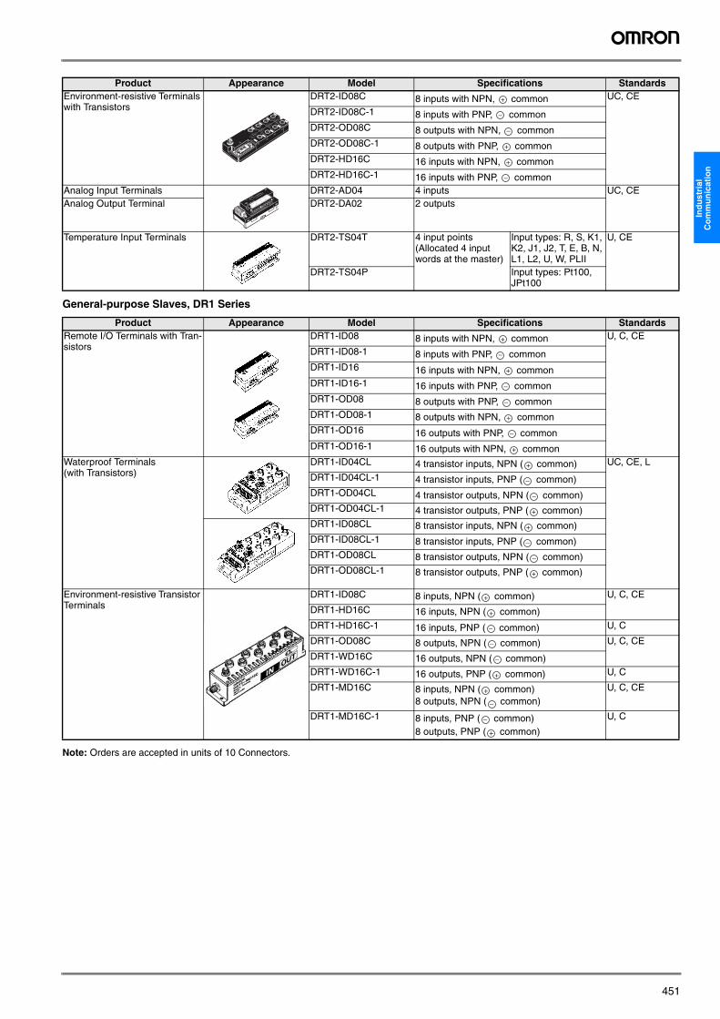
General-purpose Slaves, DR1 Series
Note: Orders are accepted in units of 10 Connectors.
Environment-resistive Terminals with Transistors
DRT2-ID08C 8 inputs with NPN, common UC, CE
DRT2-ID08C-1 8 inputs with PNP, commonDRT2-OD08C 8 outputs with NPN, commonDRT2-OD08C-1 8 outputs with PNP, commonDRT2-HD16C 16 inputs with NPN, commonDRT2-HD16C-1 16 inputs with PNP, common
Analog Input Terminals DRT2-AD04 4 inputs UC, CEAnalog Output Terminal DRT2-DA02 2 outputs
Temperature Input Terminals DRT2-TS04T 4 input points(Allocated 4 input words at the master)
Input types: R, S, K1, K2, J1, J2, T, E, B, N, L1, L2, U, W, PLII
U, CE
DRT2-TS04P Input types: Pt100, JPt100
Product Appearance Model Specifications StandardsRemote I/O Terminals with Tran-sistors
DRT1-ID08 8 inputs with NPN, common U, C, CE
DRT1-ID08-1 8 inputs with PNP, commonDRT1-ID16 16 inputs with NPN, commonDRT1-ID16-1 16 inputs with PNP, commonDRT1-OD08 8 outputs with PNP, commonDRT1-OD08-1 8 outputs with NPN, commonDRT1-OD16 16 outputs with PNP, commonDRT1-OD16-1 16 outputs with NPN, common
Waterproof Terminals (with Transistors)
DRT1-ID04CL 4 transistor inputs, NPN ( common) UC, CE, L
DRT1-ID04CL-1 4 transistor inputs, PNP ( common)DRT1-OD04CL 4 transistor outputs, NPN ( common)DRT1-OD04CL-1 4 transistor outputs, PNP ( common)DRT1-ID08CL 8 transistor inputs, NPN ( common)DRT1-ID08CL-1 8 transistor inputs, PNP ( common)DRT1-OD08CL 8 transistor outputs, NPN ( common)DRT1-OD08CL-1 8 transistor outputs, PNP ( common)
Environment-resistive Transistor Terminals
DRT1-ID08C 8 inputs, NPN ( common) U, C, CE
DRT1-HD16C 16 inputs, NPN ( common)DRT1-HD16C-1 16 inputs, PNP ( common) U, C
DRT1-OD08C 8 outputs, NPN ( common) U, C, CE
DRT1-WD16C 16 outputs, NPN ( common)DRT1-WD16C-1 16 outputs, PNP ( common) U, C
DRT1-MD16C 8 inputs, NPN ( common)8 outputs, NPN ( common)
U, C, CE
DRT1-MD16C-1 8 inputs, PNP ( common)8 outputs, PNP ( common)
U, C
Product Appearance Model Specifications Standards
+
−
−
+
+
−
+
−
+
−
−
+
−
+
+
−
−
+
+
−
−
+
+
+
−
−
−
+
+
−
−
+
Y201-EN2-03.book Seite 451 Donnerstag, 13. April 2006 9:40 09
452 Industrial Communication
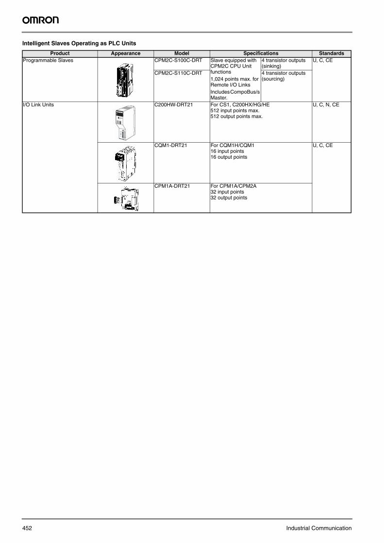
Intelligent Slaves Operating as PLC Units
Product Appearance Model Specifications StandardsProgrammable Slaves CPM2C-S100C-DRT Slave equipped with
CPM2C CPU Unit functions 1,024 points max. for Remote I/O LinksIncludes CompoBus/s Master.
4 transistor outputs (sinking)
U, C, CE
CPM2C-S110C-DRT 4 transistor outputs (sourcing)
I/O Link Units C200HW-DRT21 For CS1, C200HX/HG/HE512 input points max.512 output points max.
U, C, N, CE
CQM1-DRT21 For CQM1H/CQM116 input points16 output points
U, C, CE
CPM1A-DRT21 For CPM1A/CPM2A32 input points32 output points
Y201-EN2-03.book Seite 452 Donnerstag, 13. April 2006 9:40 09
453
Ind
ust
rial
C
om
mu
nic
atio
n
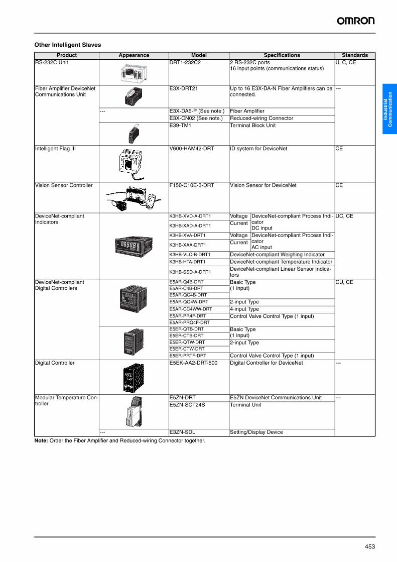
Other Intelligent Slaves
Product Appearance Model Specifications StandardsRS-232C Unit DRT1-232C2 2 RS-232C ports
16 input points (communications status)U, C, CE
Fiber Amplifier DeviceNet Communications Unit
E3X-DRT21 Up to 16 E3X-DA-N Fiber Amplifiers can be connected.
---
--- E3X-DA6-P (See note.) Fiber AmplifierE3X-CN02 (See note.) Reduced-wiring ConnectorE39-TM1 Terminal Block Unit
Intelligent Flag III V600-HAM42-DRT ID system for DeviceNet CE
Vision Sensor Controller F150-C10E-3-DRT Vision Sensor for DeviceNet CE
DeviceNet-compliant Indicators
K3HB-XVD-A-DRT1 Voltage DeviceNet-compliant Process Indi-catorDC input
UC, CE
K3HB-XAD-A-DRT1 Current
K3HB-XVA-DRT1 Voltage DeviceNet-compliant Process Indi-catorAC inputK3HB-XAA-DRT1 Current
K3HB-VLC-B-DRT1 DeviceNet-compliant Weighing IndicatorK3HB-HTA-DRT1 DeviceNet-compliant Temperature Indicator
K3HB-SSD-A-DRT1DeviceNet-compliant Linear Sensor Indica-tors
DeviceNet-compliant Digital Controllers
E5AR-Q4B-DRT Basic Type(1 input)
CU, CEE5AR-C4B-DRTE5AR-QC4B-DRT
E5AR-QQ4W-DRT 2-input TypeE5AR-CC4WW-DRT 4-input TypeE5AR-PR4F-DRT Control Valve Control Type (1 input)E5AR-PRQ4F-DRTE5ER-QTB-DRT Basic Type
(1 input)E5ER-CTB-DRTE5ER-QTW-DRT 2-input TypeE5ER-CTW-DRT
E5ER-PRTF-DRT Control Valve Control Type (1 input)Digital Controller E5EK-AA2-DRT-500 Digital Controller for DeviceNet ---
Modular Temperature Con-troller
E5ZN-DRT E5ZN DeviceNet Communications Unit ---E5ZN-SCT24S Terminal Unit
--- E3ZN-SDL Setting/Display Device
Note: Order the Fiber Amplifier and Reduced-wiring Connector together.
Y201-EN2-03.book Seite 453 Donnerstag, 13. April 2006 9:40 09
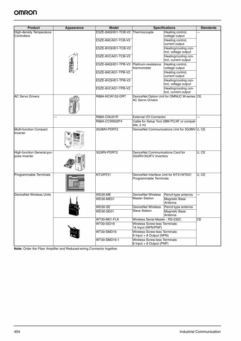
454 Industrial Communication
High-density Temperature Controllers
E5ZE-8AQHD1-TCB-V2 Thermocouple Heating control, voltage output
---
E5ZE-8ACAD1-TCB-V2 Heating control, current output
E5ZE-8VQHD1-TCB-V2 Heating/cooling con-trol, voltage output
E5ZE-8VCAD1-TCB-V2 Heating/cooling con-trol, current output
E5ZE-8AQHD1-TPB-V2 Platinum-resistance thermometer
Heating control, voltage output
E5ZE-8ACAD1-TPB-V2 Heating control, current output
E5ZE-8VQHD1-TPB-V2 Heating/cooling con-trol, voltage output
E5ZE-8VCAD1-TPB-V2 Heating/cooling con-trol, current output
AC Servo Drivers R88A-NCW152-DRT DeviceNet Option Unit for OMNUC W-series AC Servo Drivers
CE
--- R88A-CNU01R External I/O Connector ---R88A-CCW002P4 Cable for Setup Tool (IBM PC/AT or compat-
ible, 2 m)Multi-function Compact Inverter
3G3MV-PDRT2 DeviceNet Communications Unit for 3G3MV U, CE
High-function General-pur-pose Inverter
3G3RV-PDRT2 DeviceNet Communications Card for 3G3RV/3G3FV Inverters
U, CE
Programmable Terminals NT-DRT21 DeviceNet Interface Unit for NT31/NT631 Programmable Terminals
U, CE
DeviceNet Wireless Units WD30-ME DeviceNet Wireless Master Station
Pencil-type antenna ---WD30-ME01 Magnetic Base
AntennaWD30-SE DeviceNet Wireless
Slave StationPencil-type antenna
WD30-SE01 Magnetic Base Antenna
WT30-M01-FLK Wireless Serial Master : RS-232C CEWT30-SID16 Wireless Screw-less Terminals:
16 Input (NPN/PNP)WT30-SMD16 Wireless Screw-less Terminals:
8 Input + 8 Output (NPN)WT30-SMD16-1 Wireless Screw-less Terminals:
8 Input + 8 Output (PNP)
Product Appearance Model Specifications Standards
Note: Order the Fiber Amplifier and Reduced-wiring Connector together.
NCW152
1
23
4 5
67
8
1
23
4 5
67
8
1
23
4 5
67
8
MSNS
CN6
CN4
L1
L2
+ 1
+2
L1CL2CB1
B2
U
W
V
DATA/CHARGE POWER
CN3
CN1
CN2
MODE/SET
200V
R88D-WTA5HAC SERVO DRIVER
50W
U
V
W
-
+
2
+
1
L
2
L1
B2
B1
L2C
L1C
X10
X1
DR
CN11
Y201-EN2-03.book Seite 454 Donnerstag, 13. April 2006 9:40 09
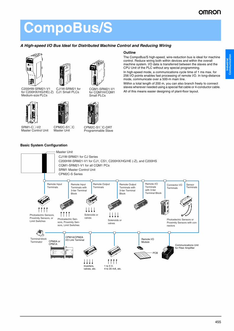
455
Ind
ust
rial
C
om
mu
nic
atio
n
CompoBus/SA High-speed I/O Bus Ideal for Distributed Machine Control and Reducing Wiring
OutlineThe CompoBus/S high-speed, wire-reduction bus is ideal for machine control. Reduce wiring both within devices and within the overall machine system. I/O data is transferred between the slaves and the CPU Unit of the PLC without any special programming. In high-speed mode, a communications cycle time of 1 ms max. for 256 I/O points enables fast processing of remote I/O. In long-distance mode, communicate over a 500-m main line.Within a total length of 200 m, you can also branch freely to connect slaves wherever needed using a special flat cable or 4-conductor cable. All of this means easier designing of plant-floor layout.
Basic System Configuration
SRM1-C@-V2 Master Control Unit
CPM2C-S1@C-DRT Programmable Slave
CPM2C-S1@C Master Unit
C200HW-SRM21-V1 for C200HX/HG/HE(-Z) Medium-size PLCs
CQM1-SRM21-V1 for CQM1H/CQM1 Small PLCs
CJ1W-SRM21 for CJ1 Small PLCs
I NO U T
N o .
SRT21CPM1A
Master Unit
Remote Input Terminals
Remote OutputTerminals
Sensor Terminals
Photoelectric Sensors,Proximity Sensors, orLimit Switches
Solenoids or valves
Photoelectric Sensors orProximity Sensors with con-nectors
Remote Input Terminals with3-tier TerminalBlock
Photoelectric Sen-sors, Proximity Sen-sors, Limit Switches
Remote OutputTerminals with3-tier TerminalBlock
Remote I/O Terminalswith 3-tierTerminal Block
Connector I/O Terminals
Solenoids or valves
Remote I/OModule
PCB
Communications Unit for Fiber Amplifier
CPM1A/CPM2AI/O Link TerminalCPM2A or
CPM1A
Inverters, valves, etc.
1 to 5 V, 4 to 20 mA, etc.
CJ1W-SRM21 for CJ SeriesC200HW-SRM21-V1 for CJ1, CS1, C200HX/HG/HE (-Z), and C200HSCQM1-SRM21-V1 for all CQM1 PCsSRM1 Master Control UnitCPM2C-S Series
Terminal-block Terminator
Y201-EN2-03.book Seite 455 Donnerstag, 13. April 2006 9:40 09
456 Industrial Communication
Features
CompoBus/S - a high-speed fieldbus for 128 inputs and 128 outputsCompoBus/S is a very fast, and easy to install high-speed bus for use with sensors and actuators. The amount of wiring that is required is minimal, making CompoBus/S ideal for machine control.
A complete line-up of master units and slavesCompobus/S allows digital and anlogue I/O signals to be exchanged between a master and the distributed I/O slaves over a flat cable or standard twisted cable over max. 500 meters. It requires no special software tools making it an real I/O bus that puts the PLC I/O on a remote location, without any additional programming effort.
Communication distances up to 500 mIn Long-distance Communications Mode, communications over the main line of up to 500 m are possible to control I/O devices in a wide area using standard cable and up to 200 m if flat cable is used. In the high-speed communications mode, the main line is limited to 100 m for standard cable, and 30 m for flat cable.
High-speed CommunicationsIn High-speed Communications Mode, up to 16 Slaves with 128 I/O. In the 100 meter high-speed mode there is a fixed communication cycle time of 0.8 msec for 256 remote I/O, providing CompoBus/S with an unprecedented performance.
Backwards compatibleRemote I/O communications are also possible in high-speed communi-cations mode by combining these Master Units and slaves with pre-viously released master units and slaves.
Free topologyWithin a total lenght of 200 meters, you can also branch freely to con-nect slaves wherever needed. Only one cable is required to connect a master to a slave or a slave to another slave. If a special flat cable with 4 conductors is used, the communications power supply can also be drawn from the same cable to greatly reduce the amount of floor wiring. Branching from the main line to branch lines is also greatly simplified with a special connector.Both the T-branch and multidrop methods can be combined flexibly when wiring. This wiring feature allows a very flexible system configu-ration that can be adjusted to the floor layout. There are two types of cables (VCTF cable and Special Flat Cable), and when the Special Flat Cable is used, T-branch Connectors can be installed by simply snapping the connector on.
Easy startup and maintenanceThe CompoBus/S System can be started just by wiring the cables and making some simple settings, and the power up the system!Troubleshooting is easy because the Slave’s node number is shown on the master’s indicators if an error occurs with a Slave. Error information is also stored in PLC memory.
Wide variety of mastersSeperate PLC master units are available, or you can use a SRM or CPM2C with an integrated Compobus/S master function in the CPU. The variety of Masters provides flexibility in configuring a system to match your application needs.
Wide variety of slavesUnits in a wide range are available as I/O Slaves for a variety of appli-cations. The variety of Slaves provides flexibility in configuring a system to match the required application.
Connectability for Upgraded Terminals
Note: 1. All of the SRT2 Series except for the SRT2-AD04 and SRT2-DA02.
Slave series Previous Master UnitsC200HW-SRM21CQM1-SRM21SRM1-C01(-V1)SRM1-C02(-V1)3G8B3-SRM00/01C200PC-ISA02/12-SRM
Master Units manufactured April 1999 or laterCJ1W-SRM21C200HW-SRM21-V1CQM1-SRM21-V1SRM1-C01-V2SRM1-C02-V2TP1000-A-SRMC200PC-ISA03/13-SRMCPM2C-S100C/S110CCPM2C-S100C/S110C-DRTCommunications mode settingHigh-speed Long-distance
SRT1 Series FND-X#-SRT
Connectable Connectable ---
SRT2 Series (See note 1.)CPM2C-SRT21CPM1A-SRT21
Connectable Connectable Connectable
SRT2-AD04SRT2-DA02
--- Connectable Connectable
Y201-EN2-03.book Seite 456 Donnerstag, 13. April 2006 9:40 09
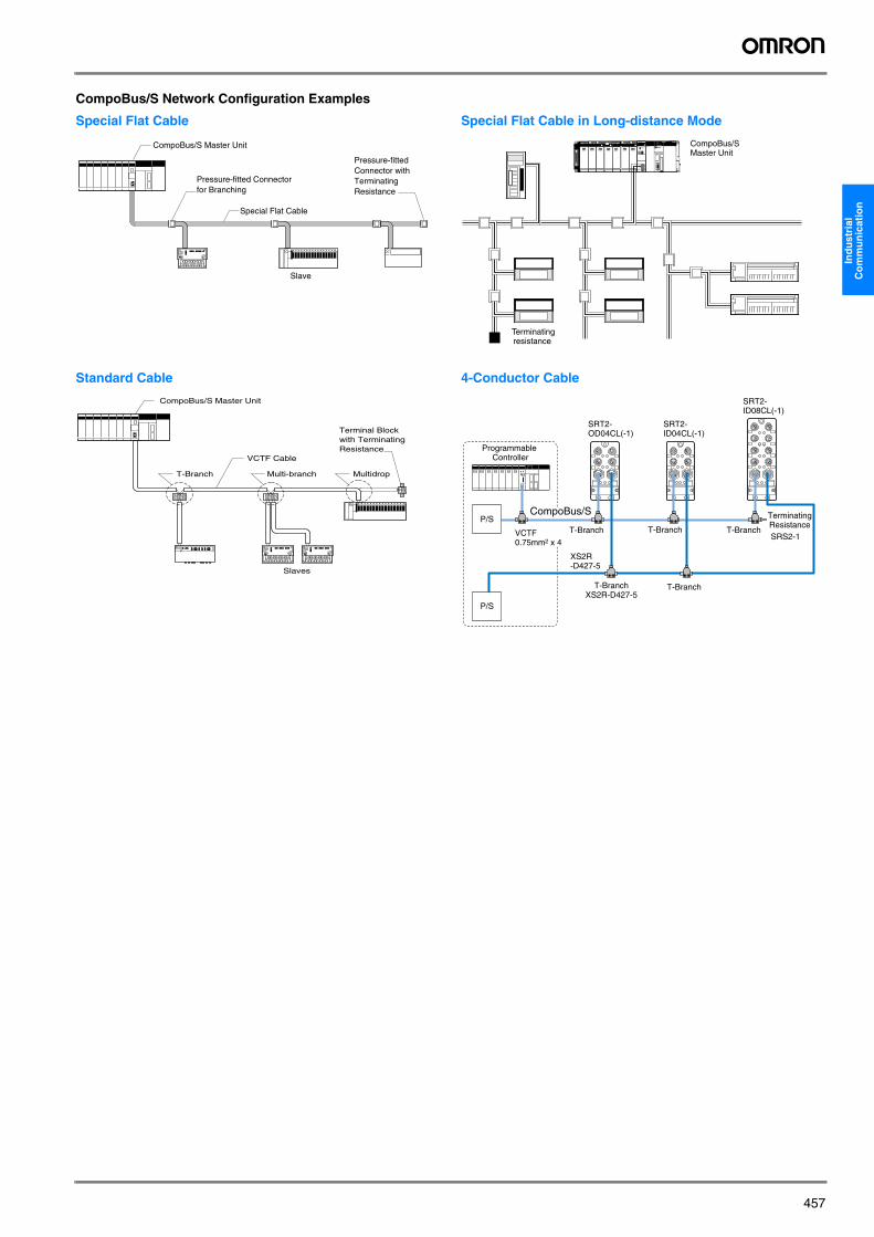
457
Ind
ust
rial
C
om
mu
nic
atio
n
CompoBus/S Network Configuration Examples
Special Flat Cable
Standard Cable
Special Flat Cable in Long-distance Mode
4-Conductor Cable
Pressure-fitted Connector for Branching
Special Flat Cable
Slave
Pressure-fitted Connector withTerminatingResistance
CompoBus/S Master Unit
CompoBus/S Master Unit
VCTF Cable
T-Branch Multi-branch Multidrop
Terminal Blockwith TerminatingResistance
Slaves
CompoBus/S Master Unit
Terminatingresistance
P/S
P/S
SRT2-OD04CL(-1)
SRT2-ID04CL(-1)
SRT2-ID08CL(-1)
CompoBus/S
T-BranchXS2R-D427-5
T-Branch
T-BranchVCTF 0.75mm2 x 4
T-Branch T-BranchSRS2-1
TerminatingResistance
XS2R-D427-5
Programmable Controller
Y201-EN2-03.book Seite 457 Donnerstag, 13. April 2006 9:40 09
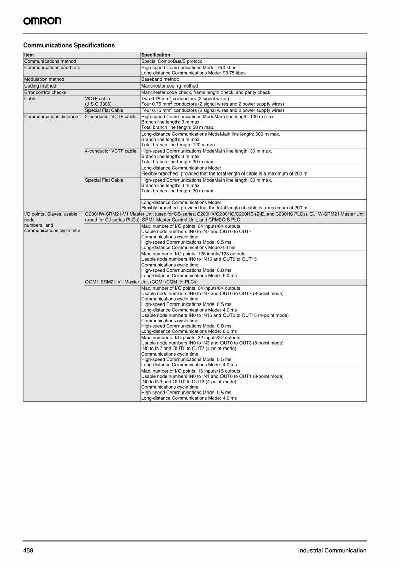
458 Industrial Communication
Communications Specifications
Item SpecificationCommunications method Special CompoBus/S protocolCommunications baud rate High-speed Communications Mode: 750 kbps
Long-distance Communications Mode: 93.75 kbps Modulation method Baseband methodCoding method Manchester coding methodError control checks Manchester code check, frame length check, and parity checkCable VCTF cable
(JIS C 3306)Two 0.75 mm2 conductors (2 signal wires)Four 0.75 mm2 conductors (2 signal wires and 2 power supply wires)
Special Flat Cable Four 0.75 mm2 conductors (2 signal wires and 2 power supply wires) Communications distance 2-conductor VCTF cable High-speed Communications ModeMain line length: 100 m max.
Branch line length: 3 m max.Total branch line length: 50 m max.Long-distance Communications ModeMain line length: 500 m max.Branch line length: 6 m max.Total branch line length: 120 m max.
4-conductor VCTF cable High-speed Communications ModeMain line length: 30 m max.Branch line length: 3 m max.Total branch line length: 30 m max.Long-distance Communications Mode: Flexibly branched, provided that the total length of cable is a maximum of 200 m.
Special Flat Cable High-speed Communications ModeMain line length: 30 m max.Branch line length: 3 m max.Total branch line length: 30 m max.
Long-distance Communications Mode: Flexibly branched, provided that the total length of cable is a maximum of 200 m.
I/O points, Slaves, usable node numbers, and communications cycle time
C200HW-SRM21-V1 Master Unit (used for CS-series, C200HX/C200HG/C200HE-(Z)E, and C200HS PLCs), CJ1W-SRM21 Master Unit (used for CJ-series PLCs), SRM1 Master Control Unit, and CPM2C-S PLC
Max. number of I/O points: 64 inputs/64 outputsUsable node numbers:IN0 to IN7 and OUT0 to OUT7Communications cycle time:High-speed Communications Mode: 0.5 msLong-distance Communications Mode:4.0 msMax. number of I/O points: 128 inputs/128 outputsUsable node numbers:IN0 to IN15 and OUT0 to OUT15Communications cycle time: High-speed Communications Mode: 0.8 msLong-distance Communications Mode: 6.0 ms
CQM1-SRM21-V1 Master Unit (CQM1/CQM1H PLCs)Max. number of I/O points: 64 inputs/64 outputsUsable node numbers:IN0 to IN7 and OUT0 to OUT7 (8-point mode)Communications cycle time:High-speed Communications Mode: 0.5 msLong-distance Communications Mode: 4.0 msUsable node numbers:IN0 to IN15 and OUT0 to OUT15 (4-point mode)Communications cycle time:High-speed Communications Mode: 0.8 msLong-distance Communications Mode: 6.0 msMax. number of I/O points: 32 inputs/32 outputsUsable node numbers:IN0 to IN3 and OUT0 to OUT3 (8-point mode)IN0 to IN7 and OUT0 to OUT7 (4-point mode)Communications cycle time: High-speed Communications Mode: 0.5 msLong-distance Communications Mode: 4.0 msMax. number of I/O points: 16 inputs/16 outputsUsable node numbers:IN0 to IN1 and OUT0 to OUT1 (8-point mode)IN0 to IN3 and OUT0 to OUT3 (4-point mode)Communications cycle time:High-speed Communications Mode: 0.5 msLong-distance Communications Mode: 4.0 ms
Y201-EN2-03.book Seite 458 Donnerstag, 13. April 2006 9:40 09
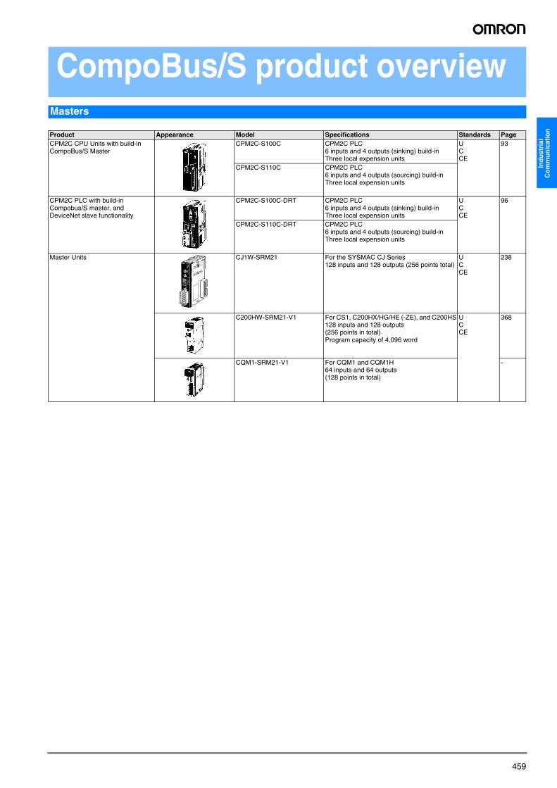
459
Ind
ust
rial
C
om
mu
nic
atio
n
CompoBus/S product overviewMasters
Product Appearance Model Specifications Standards PageCPM2C CPU Units with build-in CompoBus/S Master
CPM2C-S100C CPM2C PLC6 inputs and 4 outputs (sinking) build-in Three local expension units
UCCE
93
CPM2C-S110C CPM2C PLC6 inputs and 4 outputs (sourcing) build-in Three local expension units
CPM2C PLC with build-in Compobus/S master, and DeviceNet slave functionality
CPM2C-S100C-DRT CPM2C PLC6 inputs and 4 outputs (sinking) build-in Three local expension units
UCCE
96
CPM2C-S110C-DRT CPM2C PLC6 inputs and 4 outputs (sourcing) build-in Three local expension units
Master Units CJ1W-SRM21 For the SYSMAC CJ Series128 inputs and 128 outputs (256 points total)
UCCE
238
C200HW-SRM21-V1 For CS1, C200HX/HG/HE (-ZE), and C200HS128 inputs and 128 outputs (256 points in total)Program capacity of 4,096 word
UCCE
368
CQM1-SRM21-V1 For CQM1 and CQM1H64 inputs and 64 outputs(128 points in total)
-
Y201-EN2-03.book Seite 459 Donnerstag, 13. April 2006 9:40 09
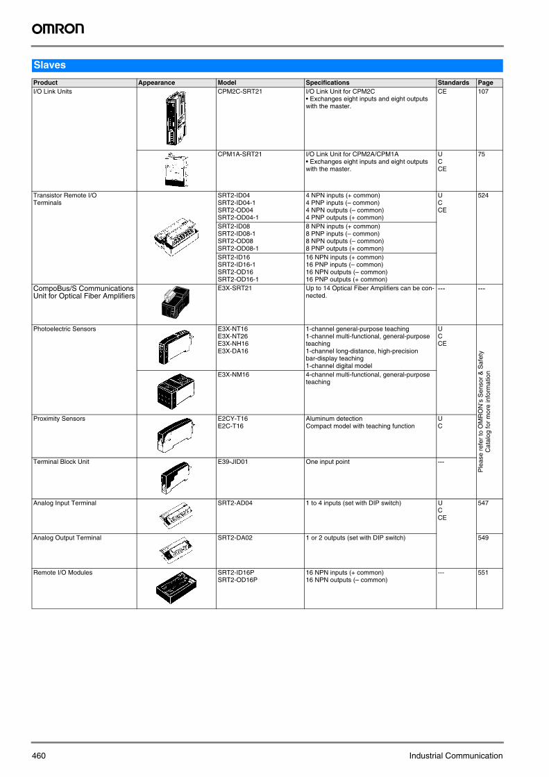
460 Industrial Communication
Slaves
Product Appearance Model Specifications Standards PageI/O Link Units CPM2C-SRT21 I/O Link Unit for CPM2C
• Exchanges eight inputs and eight outputs with the master.
CE 107
CPM1A-SRT21 I/O Link Unit for CPM2A/CPM1A• Exchanges eight inputs and eight outputs with the master.
UCCE
75
Transistor Remote I/O Terminals
SRT2-ID04SRT2-ID04-1SRT2-OD04SRT2-OD04-1
4 NPN inputs (+ common)4 PNP inputs (– common)4 NPN outputs (– common)4 PNP outputs (+ common)
UCCE
524
SRT2-ID08SRT2-ID08-1SRT2-OD08SRT2-OD08-1
8 NPN inputs (+ common)8 PNP inputs (– common)8 NPN outputs (– common)8 PNP outputs (+ common)
SRT2-ID16SRT2-ID16-1SRT2-OD16SRT2-OD16-1
16 NPN inputs (+ common)16 PNP inputs (– common)16 NPN outputs (– common)16 PNP outputs (+ common)
CompoBus/S Communications Unit for Optical Fiber Amplifiers
E3X-SRT21 Up to 14 Optical Fiber Amplifiers can be con-nected.
--- ---
Photoelectric Sensors E3X-NT16E3X-NT26E3X-NH16E3X-DA16
1-channel general-purpose teaching1-channel multi-functional, general-purpose teaching1-channel long-distance, high-precision bar-display teaching1-channel digital model
UCCE
Ple
ase
refe
r to
OM
RO
N’s
Sen
sor
& S
afet
y C
atal
og fo
r m
ore
info
rmat
ionE3X-NM16 4-channel multi-functional, general-purpose
teaching
Proximity Sensors E2CY-T16E2C-T16
Aluminum detectionCompact model with teaching function
UC
Terminal Block Unit E39-JID01 One input point ---
Analog Input Terminal SRT2-AD04 1 to 4 inputs (set with DIP switch) UCCE
547
Analog Output Terminal SRT2-DA02 1 or 2 outputs (set with DIP switch) 549
Remote I/O Modules SRT2-ID16PSRT2-OD16P
16 NPN inputs (+ common)16 NPN outputs (– common)
--- 551
Y201-EN2-03.book Seite 460 Donnerstag, 13. April 2006 9:40 09
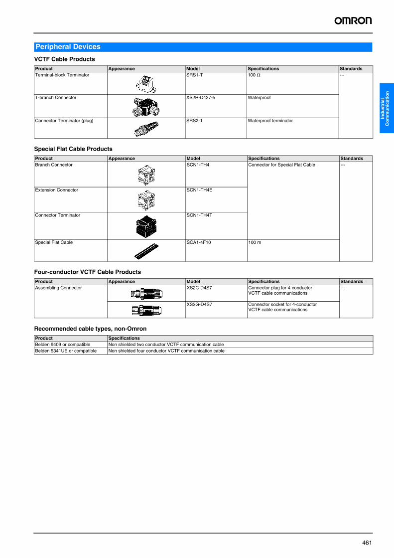
461
Ind
ust
rial
C
om
mu
nic
atio
n
VCTF Cable Products
Special Flat Cable Products
Four-conductor VCTF Cable Products
Recommended cable types, non-Omron
Peripheral Devices
Product Appearance Model Specifications StandardsTerminal-block Terminator SRS1-T 100 Ω ---
T-branch Connector XS2R-D427-5 Waterproof
Connector Terminator (plug) SRS2-1 Waterproof terminator
Product Appearance Model Specifications StandardsBranch Connector SCN1-TH4 Connector for Special Flat Cable ---
Extension Connector SCN1-TH4E
Connector Terminator SCN1-TH4T
Special Flat Cable SCA1-4F10 100 m
Product Appearance Model Specifications StandardsAssembling Connector XS2C-D4S7 Connector plug for 4-conductor
VCTF cable communications---
XS2G-D4S7 Connector socket for 4-conductor VCTF cable communications
Product SpecificationsBelden 9409 or compatible Non shielded two conductor VCTF communication cableBelden 5341UE or compatible Non shielded four conductor VCTF communication cable
Y201-EN2-03.book Seite 461 Donnerstag, 13. April 2006 9:40 09
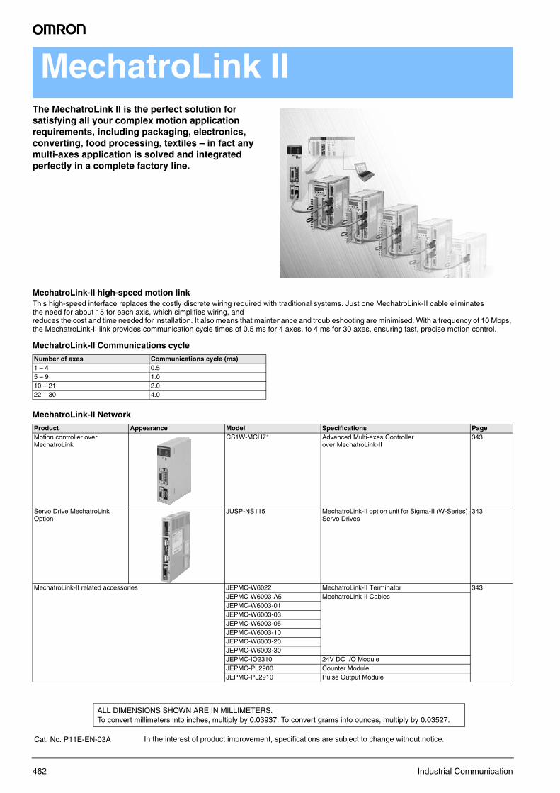
462 Industrial Communication
MechatroLink IIThe MechatroLink II is the perfect solution for satisfying all your complex motion application requirements, including packaging, electronics, converting, food processing, textiles – in fact any multi-axes application is solved and integrated perfectly in a complete factory line.
MechatroLink-II high-speed motion linkThis high-speed interface replaces the costly discrete wiring required with traditional systems. Just one MechatroLink-II cable eliminates the need for about 15 for each axis, which simplifies wiring, and reduces the cost and time needed for installation. It also means that maintenance and troubleshooting are minimised. With a frequency of 10 Mbps, the MechatroLink-II link provides communication cycle times of 0.5 ms for 4 axes, to 4 ms for 30 axes, ensuring fast, precise motion control.
MechatroLink-II Communications cycle
MechatroLink-II Network
Number of axes Communications cycle (ms)1 – 4 0.55 – 9 1.010 – 21 2.022 – 30 4.0
Product Appearance Model Specifications PageMotion controller over MechatroLink
CS1W-MCH71 Advanced Multi-axes Controller over MechatroLink-II
343
Servo Drive MechatroLink Option
JUSP-NS115 MechatroLink-II option unit for Sigma-II (W-Series) Servo Drives
343
MechatroLink-II related accessories JEPMC-W6022 MechatroLink-II Terminator 343JEPMC-W6003-A5 MechatroLink-II CablesJEPMC-W6003-01JEPMC-W6003-03JEPMC-W6003-05JEPMC-W6003-10JEPMC-W6003-20JEPMC-W6003-30JEPMC-IO2310 24V DC I/O ModuleJEPMC-PL2900 Counter ModuleJEPMC-PL2910 Pulse Output Module
In the interest of product improvement, specifications are subject to change without notice.
ALL DIMENSIONS SHOWN ARE IN MILLIMETERS.To convert millimeters into inches, multiply by 0.03937. To convert grams into ounces, multiply by 0.03527.
Cat. No. P11E-EN-03A
Y201-EN2-03.book Seite 462 Donnerstag, 13. April 2006 9:40 09