y11 mechanics and structures notes
DESCRIPTION
Engineering NotesTRANSCRIPT

Mechanics and Microstructures, Electricity Notes (Term 2) 11ES
1
Engineering Mechanics (for coplanar forces)
Reminders:
- Mechanic: a system of forces exerted and influencing a body
- Force: push/pull on a body, in SI units (Newtons)
o Coplanar/co-planar forces: forces lying on the same plane (a 2D force)
Nature and Types of Forces: four types
Concurrent: forces pass through the same point
Collinear/Co-linear: Forces lie on the same straight line (line of action)
Non-concurrent: forces intersect at various points or are parallel
Positive-negative movement of forces:
- It is necessary to define positive and negative movement
o Consistency is often best – see right
- Forces are vectors: considers magnitude (quantity) and direction
(1.) Vector Addition (of collinear forces):
- Forces in the same direction are added together
o E.g. 10N east + 10N east = 20N east
- Forces in the opposite direction are subtracted
o E.g. 10N east + 5N west = 5N east
(2.) Vector Subtraction (of collinear forces):
- Just a special case of addition
- Process can be converted to addition: the vector to be subtracted is changed to reverse its
direction (subsequently reversing its +/- sign)
o u – v = u + (–v)
o E.g. 10N east – 5N west = 10N east + 5N east = 15N east
(3.) Vector Calculations: Head to Tail
- Connect separate vectors acting on a body together in a
head-to-tail chain
- Find the resultant force vector (first tail to last head)
- Use sine and cosine rules to find both magnitude and
direction (angle/bearing)
(4.) Vector Calculations: Perpendicular Components
- All forces can be resolved in their horizontal and vertical
components (due to Pythagoras)
- Use sine, cosine to find the magnitudes of the x- and y-
components
- Find a separate total for the x- and y- components

Mechanics and Microstructures, Electricity Notes (Term 2) 11ES
2
- Use Pythagoras and sine/cosine/tan to find both the magnitude and direction of the
resultant vector (FR).
Space and Free body Diagrams
- Space: shows a realistic real-life image of a situation (i.e. drawings of people)
- Free-body (FBD): shows relevant vectors (magnitude, direction), angles and dimensions
o Also called a force-vector diagram
Resultants and Equilibrants:
- Resultant vector: net effect of a system of other forces
o Imaginary vector that has the same effect as all the other ones
- Equilibrant: an opposing force that balances a system of forces
o The opposite of the resultant vector (e.g. FR = 5kN, FE = -5kN)
Note negative magnitudes mean movement in the opposite direction
Transmissibility of Forces
- A principle explaining that a force can be relocated at any
position on its line of action to produce the same effect.
o E.g. a push has the same effect as a pull
Three Force Rule for Equilibrium
- Static equilibrium: an object at rest
- Three concurrent or parallel forces produce equilibrium (on a body).
o The vectors (magnitude and directions) of the three must together form a closed
triangle, if in equilibrium – triangle of forces rule
A closed triangle means no new resultant force is formed
- E.g. examples involving predominantly drawing:
Triangle drawn from the use of the three force rule (from the question of
the left)

Mechanics and Microstructures, Electricity Notes (Term 2) 11ES
3
- Recommended Additional Drawing Requirements: probably unnecessary
o Scale (e.g. 2cm = 1N)
o Compass
o Protractor
Example 2 (see right): Find the tension in
the cable and the reaction at the ground
as the person holds the 20kg fence post
above the ground.
1. Cable tension is given
2. Weight is found based on
knowledge
3. Third force (equilibrant force) is
implied by question as a reaction
force (causing the friction that
opposes the object falling)
4. Space diagram is constructed –
vectors are moved to form a
closed triangle (it must be closed)
5. 66° is found by measuring the
space diagram with a protractor
6. Calculations/measurements to
find tension (T) and reaction with
the ground (RG).

Mechanics and Microstructures, Electricity Notes (Term 2) 11ES
4
Summary – Procedure of the Three Force Rule:
1. Find the three forces that create equilibrium
2. Construct an accurate diagram, OR apply trigonometry through converting each vector to its
perpendicular components
3. Calculate/measure a solution to the given problem
All three-force rules for equilibrium are likely to include weight (going downwards).
Three Force Rule via Trigonometry:
1. Conversion to x- and y- components
2. Consideration of equilibrium – the three forces must equal zero
3. Construct equations of reaction forces, whilst considering direction
- E.g.
1. T1 and T2 are resolved into their components.
2. Equal and opposite reaction forces:
a. Analyse the horizontal components and their directions:
T1cosθ1 + -T2cosθ2 = 0
∴ T1cosθ1 = T2cosθ2
b. Analyse the vertical components and their directions:
T1sinθ1 + T2sinθ2 = W

Mechanics and Microstructures, Electricity Notes (Term 2) 11ES
5
Moments (of a force):
- Moment: a force that causes rotation/torque about a (pivot) point (i.e. a fulcrum)
o E.g. a lever/see-saw: does not move in a state of equilibrium. Moves up/down when
a moment is applied -> (moments relate to force-distance trade-offs in a lever)
o E.g. using a screwdriver, door hinges, bicycle pedals
- Exist as clockwise and anti-clockwise moments (their direction of rotation).
- In equilibrium, clockwise moment = anticlockwise moment (clockwise often considered +ve)
- Equation:
M = Fd
…where M = moment (Nm), F = force (N), d = perpendicular distance (m).
'r' could also be used to denote distance. In a circle/sphere (particularly in gravity), r could
refer to radius, etc.
- IF force (F) is given and is NOT PERPENDICULAR to the distance, two methods can be used to
re-construct this perpendicular force-distance relationship:
1. Components of a force: x and y
a. Conversion of a force into vertical and horizontal components,
respective to the distance, that is:
i. Vertical force component is perpendicular to the distance
ii. Horizontal component is parallel to the distance – it contributes
no force TO the moment and so is ignored
b. Use of the standard M = Fd equation
2. True Moment Arm: finds distance perpendicular via Pythagoras/trigonometry
a. Converts the given distance into a distance perpendicular to the force,
commonly using cosine
b. Use of the standard M = Fd equation
Couples:
- Couple: two anti-parallel (parallel in opposite directions) coplanar
forces of identical magnitude but opposite sense (direction/arrowhead)
o Also known as 'torqueing around' (because couples are not commonly used): note
this statement is invalid and meaningless in physics
o Creates rotation without translation (no acceleration of the centre of mass – due to
the magnitude of each force being identical)
- Difference to a moment:
o A moment consists of only one force
o Couples are two opposing forces, producing no net force

Mechanics and Microstructures, Electricity Notes (Term 2) 11ES
6
However, the force is not placed at the centre, causing the couple to impart
rotation. [?]
- Equation:
Torque = Mc = Fd [scalar analysis]
Torque = Mc = Fr [vector analysis]
…where Mc (or 'τ') = moment of a couple (Nm), F = force (N), d (or r) = perpendicular
distance (m).
- Question: what forces are required to produce a couple to turn a tap handle…?
1. Do the calculations involving the formula
2. Find the necessary magnitude of the force
3. Acknowledge that to produce a couple, TWO forces of this magnitude is
required, not one.
Force/Couples: an extension of couples
- Equilibrium: requires a vertical force to prevent the body falling (gravity), and a couple to
prevent it rotating
IMPORTANT: "When a couple is considered, one of the 'spouses' can be placed at the origin,
producing 0 torque (Mc = F*0). Meanwhile the other is not at the centre and thus a non-zero value
(that can have the same magnitude as a moment). The difference is that a whole couple has a total
force of 0, while a moment acts separately and thus has a nonzero ordinary force."
Conversion of a Force to Force/Couple:
1. An active force acts perpendicularly to a distance from the fulcrum (e.g. of a shelf). It acts as
a moment.
2. To create equilibrium, symbolically add two forces that cancel each other out (i.e. they are
opposite in direction of one another), at the fulcrum. These represent weight placed on the
fulcrum (or the wall supporting the shelf).
3. Reconsider the original active force, or moment. A couple is also required to prevent
rotation of the body (shelf) – this is already created by it and the reaction force in Step 2.
4. These two forces can then be combined to form a couple. Its moment is determined using
Mc = Fd. It can be moved anywhere along the line of action of the body (towards or away
from the fulcrum -> distance and force will change respectively with no change).
E.g. a weight on a shelf and the force/couple system that results, acting on the wall

Mechanics and Microstructures, Electricity Notes (Term 2) 11ES
7
Conversion of a Force/Couple to Force: reverse process
1. Process starts off with a force/couple system
2. The couple can be reconverted back into two opposite forces. Magnitude and direction is
based off the isolated force vector in the system
a. Magnitude – same for each vector
b. Direction – parallel to the isolated force vector
3. The two vectors of the couple cancel out – the diagram is reconverted back into a moment
(a force exerted a distance apart from a pivot)
Reactive Couples
- One couple can only be balanced by another couple – couples do not balance forces or
moments [is this contradictive?]
o I.e. an active couple is balanced by a reactive couple, that reacts in the opposite
direction

Mechanics and Microstructures, Electricity Notes (Term 2) 11ES
8
Equilibrium of Concurrent Force Systems:
- Equilibrium: a force system is balanced – there is no resultant
- Most force systems are in equilibrium – this can be used to help solve unknown forces
- If there are three forces and they are in equilibrium they will also be concurrent (Three Force
Rule)
Conditions:
1. No resultant force
2. Force polygon (vector) closes (as seen in the Three Force Rule)
3. Sum of all force components and moments equal zero:
a. ΣFV = 0
b. ΣFH =0
c. ΣM = 0
Engineering Materials
Modification of Materials:
- Physical, mechanical, chemical, etc. changes within a material
- Creates new desired properties to meet certain tasks
Work Hardening (or strain hardening/cold working):
- Crystalline structure: consists of dislocations that are defects on an atomic level and induce
weakness in the material
o Dislocations can be visualised as interruptions/terminations in planes of atoms in
the middle of a crystal. They are also called slip planes or slip-lines.
- Work hardening: a process of strengthening a metal through plastic deformation – the metal
is worked (i.e. shaping, bending, hammering, rolling, drawing)
o Working produces more slip planes – initially weakening
o Further working leads to congestion of slip planes, restricting slip plane movement
(of atoms) and increasing material strength.
- Burger's vector (see right): denoted 'b', represents magnitude and direction of lattice
distortion, of a dislocation in a crystal structure.
Heat Treatment
- Classifies controlled heating and cooling to create desired structural changes in (the physical
properties of) a material
- Basic steps: heating, soaking, cooling

Mechanics and Microstructures, Electricity Notes (Term 2) 11ES
9
1. Heating:
o Structure of an alloy changes when heated
o At room temperature, it is either a mechanical mixture, partial or solid solution
o Mechanical mixture: clearly visible elements/compounds in a base metal matrix
Predictably enters a partial/solid solution when heated – predictable
changes in grain size and structure
o Solid solution: solution that has absorbed two or more metals. Metals cannot be
identified even under a microscope.
o Partial solution: combination of the two
2. Soaking:
o Done in air, in a bath or a vacuum
o Evenly distributes heat across the entire body –
longer soaking for larger masses
Uneven heating or overheating should
be avoided
3. Cooling:
o Dissipation of heat – chemical composition
may change structure again in predictable ways
o Predictions allow control of hardness,
toughness, ductility, tensile strength, etc.
o Air cooling, furnace cooling, water/oil cooling
(quenching)
Quenching:
- Rapid cooling, to harden steel. Cooled in a quenching medium:
1. Water:
o One of the most efficient (fastest) mediums
o Produces maximum hardness; thus may cause distortion or tiny cracks to form
2. Oil: e.g. whale, cottonseed, mineral oils
o Sacrifices hardness for more stable results
o Oils oxidise and form a sludge, lowering the efficiency of quenching
3. Inert gases: e.g. nitrogen (most common), helium
4. (Forced) Air

Mechanics and Microstructures, Electricity Notes (Term 2) 11ES
10
Microstructures:
- Microstructure: microscopic appearance of a material's surface (nm-cm level)
o Note: a crystal structure is an atomic level appearance
o Influential to physical properties
o Classified in metallic, polymeric, ceramic and composite categories
Cubic Crystal System:
- A crystal system with the unit cell in the shape of a cube
- Main varieties (3):
Iron-carbon system (of microstructures)
- Ferrite: BCC structure
o Ferrite contains iron and small amounts of carbon up to 0.04%C
o Also known as alpha iron (α-Fe) or delta iron (δ-Fe, which is more stable)
o More ferrite -> increases softness, toughness and ductility
- Austenite: FCC structure
o Austenite contains iron and a carbon content of up to 2%C
o Also known as gamma iron (γ-Fe)
o Grain structure that forms when steel is at red heat (723-1500°C)
o FCC crystal system is denser than BCC – more slip planes
Further increase in softness and ductility (when steel is red-hot)
- Cementite:
o A compound where iron has absorbed carbon: Fe3C
o Formed upon the cooling of austenite from red heat, which breaks down into ferrite
and excess, unabsorbed carbon (existing as graphite/cementite)
o Extremely hard and brittle
Analogy: like cement in concrete
- Pearlite:
o A lamellar (layered) structure of ferrite and cementite, in alternating bands
Typically 88% ferrite, 12% cementite
o Formed upon the cooling of austenite from red heat
that creates both ferrite and cementite. If the carbon is
diffused at small distances (due to still being solid),
plates of cementite form, creating the layered structure.
Pearlite looks like a pearl under a microscope,
hence its name
o Is hard, strong and half as ductile as ferrite
Empty point
here causes a
cubic void

Mechanics and Microstructures, Electricity Notes (Term 2) 11ES
11
o Steels with 0.8%C only have pearlite grains
Microstructure Sketching:
- Visibility: a smooth, polished metal surface shows no detail – light waves are reflected along
the same path they enter
- Etching:
1. A smooth surface is lightly etched (eaten away by a special acid)
2. Grain boundaries are corroded/attacked first (due to higher energy levels),
producing small grooves. Grain boundaries are made visible.
3. Further etching erodes grains at different rates depending on grain orientation.
Microscopic surface of the metal is made uneven, thus grains are made visible.
a. Heavy etching will result in the surface being too dark to determine
individual grains
4. Repolishing of the surface – material is worn away to become smooth again.
Microstructure patterns are invisible again.
Method of Sketching Steel Microstructures
1. Sketch equiaxed grains (crystals with axes of the same length) for annealed materials
2. Fill in the pearlite (represented as striped grains) [?]
a. Ferrite is represented in white [?]
- Always label microstructures
Proportions of ferrite/pearlite in annealed plain carbon steels:
Carbon Content Ferrite grains (white) Pearlite grains (striped)
0%C 100% 0%
0.2%C 75% 25%
0.4%C 50% 50%
0.6%C 25% 75%
0.8%C 0% 100%
>0.8%C Network of cementite (black?) around pearlite

Mechanics and Microstructures, Electricity Notes (Term 2) 11ES
12
Heat Treatment Procedures in Ferrous Metals
1. Hardening:
o Metal with sufficient carbon (>0.3%) is heated to a correct temperature (to red heat
–> austenitising temperature) before rapidly cooled via quenching
o Increases hardness and brittleness:
o FCC austenite is not given time to change to BCC ferrite because of rapid cooling –
produces a (vertically) distorted BCC, called a BCT (body centred tetragonal)
Forms BCT martensite – needle-like structure, too hard and brittle (requiring
tempering)
2. Tempering:
o Metal is heated to a certain temperature (200-600°C, well below the lower critical
temp. of 723°C), soaked to remove internal stresses (structural changes return to
equilibrium), and then cooled in still air.
Increased temperature -> increases softening and ductility, reduces tensile
strength, yield stress, hardness
Rate of cooling does not affect structure, for plain carbon steels
o Relieves internal stresses after steel has been hardened (in most circumstances)
This is because hardened steel is usually too hard/brittle to work with
High speed steel: tempering actually increases hardness
o Carbon atoms trapped in the BCT martensite are diffused to form fine cementite –
sub-microscopic changes. New microstructure called a 'tempered martensite'.
3. Annealing:
o Metal is heated to and soaked for a period of time at a specific temperature before
being cooled back to room temperature
o Produces maximum softness when slowly cooled, e.g.:
Packaging: burying the metal in non-readily conductive heat surfaces
E.g. sand, ash
Furnace cooling: material is cooled inside and alongside the furnace
o Relieves internal stresses, softens them for further working/machining, increases
ductility, produces a uniform grain structure (meaning less weaknesses)

Mechanics and Microstructures, Electricity Notes (Term 2) 11ES
13
o Full annealing: steel is heated to red heat (~900°C?) and soaked to change all grains
to austenite, before very slowly furnace cooled (usually)
Oversoaking will create excessively large grains – weakens the structure
Not often used: expensive, unnecessary degree of softness and loss of
strength
o Process/immediate/sub-critical/in-process annealing: metal is heated below red
heat within the recrystallisation zone (550-650°C)
Usually used during cold-working processes with low-carbon steels (<0.3%C)
– they need the ductility and the relieving of internal stress (e.g. within sheet
and wire industries)
Recrystallises to form ferrite in equiaxed grains and elongated ('made
longer') pearlite grains
Equiaxed grains: crystals with axes of the same length – thus increased
strength and ductility
o Spherodising Annealing: metal is heated and soaked between 650-700°C for several
hours before gently furnace cooled
Softens steels with higher carbon contents (>0.3%C)
Produces spheroids of cementite in a ferrite matrix, allowing for easy
machining – cutting tool pushes the hard, brittle carbide spheres away from
the cutting edge
o Generally, in annealing, mild steel is made to austenitise (at red heat) – producing a
coarse-grain unstressed structure of ferrite and pearlite
4. Normalising:
o Metal is heating and soaked at a specified temperature (higher than in
hardening/annealing, above red heat, at >900°C) and then cooled in still air
o Increases toughness and resistance to external stress
o Comparisons to annealing: see below
o Relieves internal stresses from machining/forging/welding – improving
machinability
Particularly used on forgings and castings
Produces harder, stronger steels than annealed steels
Strongest form of steel
o Produces a uniform grain structure
A finer grain structure than in (process)
annealing – i.e. smaller grains
o Same cooling process – cools faster than
annealing due to thermal gradient

Mechanics and Microstructures, Electricity Notes (Term 2) 11ES
14
5. Case/Surface Hardening:
o A low-carbon steel (straight carbon steel/low-carbon alloy steel) is heated to a
specific temperature in the presence of a material (solid, liquid, gas)
o The material decomposes and deposits more carbon into the surface of the steel
o Allows for wear-resistant surfaces (case), soft and tough cores
o Groups of methods to achieving case hardening: see below
o Carburising: soaking the metal at red heat in a carbonaceous material/atmosphere
(a substance rich in carbon)
Increases carbon content of the case to about 0.8% - hardens the surface
Used when the core is already soft and tough (0.1-0.2%C)
o Nitriding: exposure to nitrogen
Surface composition of a steel is changed by diffusing nitrogen into it and
producing hard nitride compounds
E.g. 11th century medieval swords were hardened through urinating
on the hot sword blade (exposing the metal to NH3)
o Flame and induction hardening: used to case/surface harden steels of >0.3%C,
commonly 0.4-0.6%C
Induction: heated by electric current
For small jobs; e.g. axles, shafts
Flame: heated by a high-temperature flame and then quenched
For larger jobs; e.g. gear teeth, machine beds
Heat Treatment Procedures in Non-Ferrous Metals
- Non-ferrous metal: iron is not the base element
o Not as readily used as ferrous metals, but necessary due to unique combinations
of properties not found in ferrous alloys
- All metallic alloys can be work hardened, but not all metallic alloys can be heat treated
1. Annealing: most nonferrous metals can be annealed
o Heated and soaked at a specific temperature dependent on the type of metal,
before cooled to room temperature (standard procedure)
o Typically done after work hardening (cold working)
o Removes effects of solution heat treatment effects
Improves machinability/workability
2. Solution Heat Treating:
o Alloy is heated to create an altered mechanical mixture before quenched
o Mechanical mixture: clearly visible elements/compounds in a base metal matrix
1. Materials in the alloy change to a solid solution
2. It then reform into an altered mechanical mixture – rate and extent are
controllable
3. Quenched – rapid cooling traps the materials in the solid solution
o Increase in tensile strength from resultant grain structure
o Undergoes a process of precipitation afterwards to prevent the state reverting

Mechanics and Microstructures, Electricity Notes (Term 2) 11ES
15
Precipitation Hardening: can be applied to any alloy
- Used to harden some alloys of steel, magnesium,
aluminium, copper, titanium, nickel
1. The alloy is heated to form a homogenous (uniform)
structure
2. This structure (at the elevated temperature) is
retained via quenching to room temperature
3. The alloy is then aged (hardened and strengthened)
in two ways:
a. The alloy is allowed to stand at room
temperature for a period of time (days)
during which hardening occurs – natural
ageing
b. The alloy is heated at a slightly elevated
temperature to accelerate the process into
several hours – artificial ageing
- Resultant metals are called 'maraging steels' –
increased tensile strength (measured in Pascals)
Heat Treatment: General Procedures on Metals
- Steel: one of the most heat-treatable metals. Most heat-treatment processes involve steel.
o If plain carbon steel (>0.3%) is heated to red-hot and then quenched, it becomes
hard and brittle
o Increased carbon content increases hardness and brittleness – formation of
martensite that reflects these properties
Heat treatment induces changes in (micro-)structures
o Tempering: some stresses are relieved and a hard structure results
- Aluminium Bronze: (copper as the main component, aluminium as an additive)
o When quenched, a hard structure similar to martensite in steels is formed -> called
beta martensite
- Aluminium Copper alloys (including duralumin):
o If appropriate precipitation of a hard phase, the phase finely disperses throughout
the entire structure and strengthens the alloy
o Phase: a chemically stable single homogenous ('of the same kind') area in an alloy
- Titanium alloy:
o Can be heat-treated to form beta' or titanium martensite (as alpha'), dependent on
original proportions of alpha and beta
Titanium martensite in alpha' form is different – it is soft
o Alloy is then tempered to finely disperse the structure and strengthen the alloy
Heat Treatment: General Procedures on Ceramics
- Process -> many ceramics are 'fired' to produce their strength and rigidity
- Alumina: aluminium oxide
o Pressed to shape and then fired to bond particles
- Clay body ceramics: e.g. porcelain

Mechanics and Microstructures, Electricity Notes (Term 2) 11ES
16
o Low mechanical strength prior to firing
o Relies on firing to obtain rigidity
- Glass:
o Can be reheated after manufacturing to produce toughened glass
o Glass is heated and the outer surfaces are cooled rapidly:
Outside surfaces become rigid
As the hot inside cools it contracts, drawing the surface layers into
compression
o Increased strength: compressive stress in the outside surfaces must first be
overcome before the glass experiences tensile stress
Alloying:
- Alloy: a metal consisting of a combination of two of more elements
- Introduction of foreign atoms (symbolically represented as different in size) distorts the
lattice, blocking slips along slip planes and thus hinders dislocation movement
o Dislocations are hindered by anything that blocks the continuity of the material's
atomic array (crystal lattice)
- Improves yield strength (in comparison to the parent metal)
o Yield strength: the stress at which a material begins to
plastically deform
Alloys (Ferrous):
- Ferrous alloys: contains iron as the main constituent
o Pure iron: soft, corrodes -> little commercial use in this form
o Steel: addition of carbon (percentage of carbon content has
profound effects)
Steel: < 2%C
Plain carbon steel (0.03-1.2%C) Likely to also contain manganese and silicon to overcome sulphur and oxygen (undesired by-products of steel making processes)
Alloy steel Contain various other elements like nickel, chromium, etc.
Cast iron: 2-4%C
- Are cast to be shaped in a mould while liquid (hence their name)
Plain carbon steels
Type Carbon content Description Uses
Low carbon steel to 0.15% High ferrite content Withstands large cold working
Fence wire, rolling sheet, car bodies, stampings, rivets, chains
Mild steel 0.15-0.3% High pearlite content Very weldable up to 0.2%C Low hardenability (when red-heated and quenched)
Structural steels
Medium carbon steel 0.3 – 0.6% Predominately pearlite 0.3% - forgings, gears 0.4% - shafts, axles 0.55% - dies, rails (wear-resist.)
High carbon steel 0.6% - 1.0% Predominately pearlite & network of cementite High strength and wear resistance (0.8%C+)
Dies, spanners, hammers, punches, screwdrivers, cables
Ultra high carbon steel
1.0% - 2.0% Network cementite Tool steels – files, knives, drills, taps, axes

Mechanics and Microstructures, Electricity Notes (Term 2) 11ES
17
Alloy Steels
Addition Increased Properties Uses
Nickel Toughness Fatigue resistance
High strength structural work
Chromium Good wear resistance Ball and roller bearings – hard case with tough, shock resistant centre
Manganese Silicon
Strength Toughness
Gears, axles, shafts, punches, abrasion hardening steels
Molybdenum High temperature hardness Strength
Aircraft structures
Tungsten Good temperature wear resistance Tool steels
Vanadium Strong carbide (cementite former) Limits grain growth High toughness
Springs, crankshafts
Stainless steel
10%+ chromium Surface film of chromium oxide: Good corrosion resistance
Austenite (16-26% Cr): cookware, kitchen sinks Ferritic (12-25% Cr): car exhausts, nuts & bolts Martensitic (12-18% Cr): surgical instruments, in chemical/oil industries
High speed tool steels
Contains steel alloying elements in varying amounts
Cutting tools (drills, taps, hacksaw blades, files)
Steel: (up to 2%)
- Carbon in form of cementite (Fe3C)
Cast Irons: (2-4% carbon content)
- Name: originates from them generally cast from in a mould
- Carbon in form of graphite (weak)
Type of Cast Iron Description Uses
Grey 1.5%+ silicon for graphite to form during solidification Graphite present as flakes/plates Fractures induced at end of graphite plates (reduces tensile strength, ductility) Graphite voids (easy machining)
Intricate castings (low melting point) Heavy machine base castings Cylinder blocks (cars, lathe beds)
Nodular / spheroidal graphite (SG)
1.5%+ silicon for graphite to form during solidification Addition of magnesium/cerium Graphite present as nodules (spheres) Graphite does not produce stress concentrations (greater tensile strength, moderate ductility)
Machine castings (subject to bending and vibrating) Camshafts Mining hoist drums Piston rings
White Less than 1% silicon (no formation of graphite) Forms carbide (cementite) Carbide properties create a hard, brittle, non-ductile material
To make malleable cast iron Wear plates Demolition balls Rock crushers Insides of cement mixers
Malleable White case iron castings soaked at 870°C and slowly cooled If further heated to 970°C for 12h, a cluster of graphite forms (pearlite matrix) Graphite increases ductility (due to removal of brittle carbides and graphite flakes that produce stress concentrations)
Manhole covers Axle and differential housings Camshafts Crankshafts Expansion joints (in bridges)

Mechanics and Microstructures, Electricity Notes (Term 2) 11ES
18
Alloys (Non-Ferrous):
- Advantages of non-ferrous to ferrous metals:
o Often greater ductility – easier to work harden (cold working)
o Lower density – lower mass/weight
o Higher thermal and electrical conductivity
o Often significantly lower melting points – easier, cheap casting
o Good resistance to corrosion – special processes not necessary
o Generally non-magnetic (except alloys of nickel or cobalt)
- Advantages of ferrous to non-ferrous metals:
o Ferrous: Higher strength and stiffness (Young's modulus)
o Ferrous: Better for welding
Copper Alloys:
- Uses: electrical components, pump and valve parts, coins, instrument parts, springs, screws
- Copper-zinc alloy: brass
Cartridge brass 70% Cu, 30% Zn Soft and ductile, can be severely cold worked Uses: cartridge/shell cases, tubes, wires, sheet
High-tensile brass (Muntz metal)
60% Cu, 40% Zn High tensile strength (relative to other types of copper) Uses: marine propellers, shafts, pumps
- Copper-tin alloy: tin bronze
o Basically two types:
Wrought alloy 7% Sn (tin) Can be hot- or cold- worked Uses: sheet, strip, rod, wire, coins
Casting alloy 10-18% Sn May include lead to improve machinability Uses: corrosion resistant castings, marine castings
- Copper-tin-phosphorus: phosphor bronze
o 1% phosphorus added – improves tensile strength, corrosion resistance, and lowers
coefficient of friction
o Uses: bearings, springs, fasteners, gear wheels, turbine blades
- Copper-aluminium: aluminium bronze
o Up to 10% aluminium
o High strength and good corrosion resistance – due to thin films of surface alumina
o Uses: 'gold' coins, pump casings, gears
- Copper-nickel: cupronickel
'Silver' coinage cupronickel 25% Ni Uses: coins, knives, forks, spoons, keys, zippers
Monel metal 70% Ni High strength and corrosion resistance Uses: chemical plants, turbine blades, valves, nuts, bolts
Aluminium Alloys:
- Pure aluminium: too soft
o Aluminium is thus normally used as an alloy
o E.g. cooking foil: 99.5% pure aluminium
- Typically alloys with: copper, manganese, silicon, magnesium, zinc (at up to 10%)
- Improvements (of alloying): tensile strength, corrosion resistance, weldability, casting ability,
suitability for heat treatment (with copper and silicon)

Mechanics and Microstructures, Electricity Notes (Term 2) 11ES
19
- Properties:
o 1/3 the Young's modulus of steel
o High electrical conductivity: 60% that of Cu
o Good corrosion resistance – resistant oxide layer surface (anodising)
o Low mass
- Uses: building/aircraft industries (low mass), foil (non-toxic)
o Used in power cables due to low mass, but must be reinforced by a steel core
(aluminium has a low strength)
- Common alloys:
Duralumin 4% Cu, small % of Mg, Si, Mn
Heat-treatable, strong +Cu: higher electrical conductivity, higher corrosion resistance Uses: stressed parts in aircraft, pistons, cylinder heads, cladding
Aluminium-silicon-magnesium alloy
? Medium strength, good weldability Used as a structural alloy: furniture, truck/marine structures, race-car fabrications, pipes, railings
Aluminium-silicon alloy 9-13% Si Used in sand and die casting Uses: car stumps, gear boxes, thin walled complex castings
Titanium Alloy:
- Properties: High strength/mass ratio (specific strength), high melting point (1660°C),
excellent corrosion resistance
- Plentiful ores (rutile from sand – a mineral TiO2), expensive refinement
- Pure titanium: ½ mass of steel, relatively weak (relatively low tensile strength) to steel
o Uses: chemical plant components, surgical implants (biocompatible), marine/aircraft
engine parts
- Titanium alloy: dramatically increased tensile strength
o Uses: rocket motor cases, turbine blades, gas turbine engine cases, honeycomb
panels, high strength fasteners
Zinc Alloy:
- Properties: Low melting points, high corrosion resistance
- Typically alloys with aluminium, copper, magnesium, iron
- Mainly used for die casting
- Uses: fuels pump bodies, toys, car door handles, car body emblems
Engineering Applications of Materials
Reasons for choice of materials:
- Material suitability: properties
- Availability: (and costs)
- Processing: manufacturing (and costs)
- Cost: a secondary concern to only worry about AFTER engineering concerns are satisfied
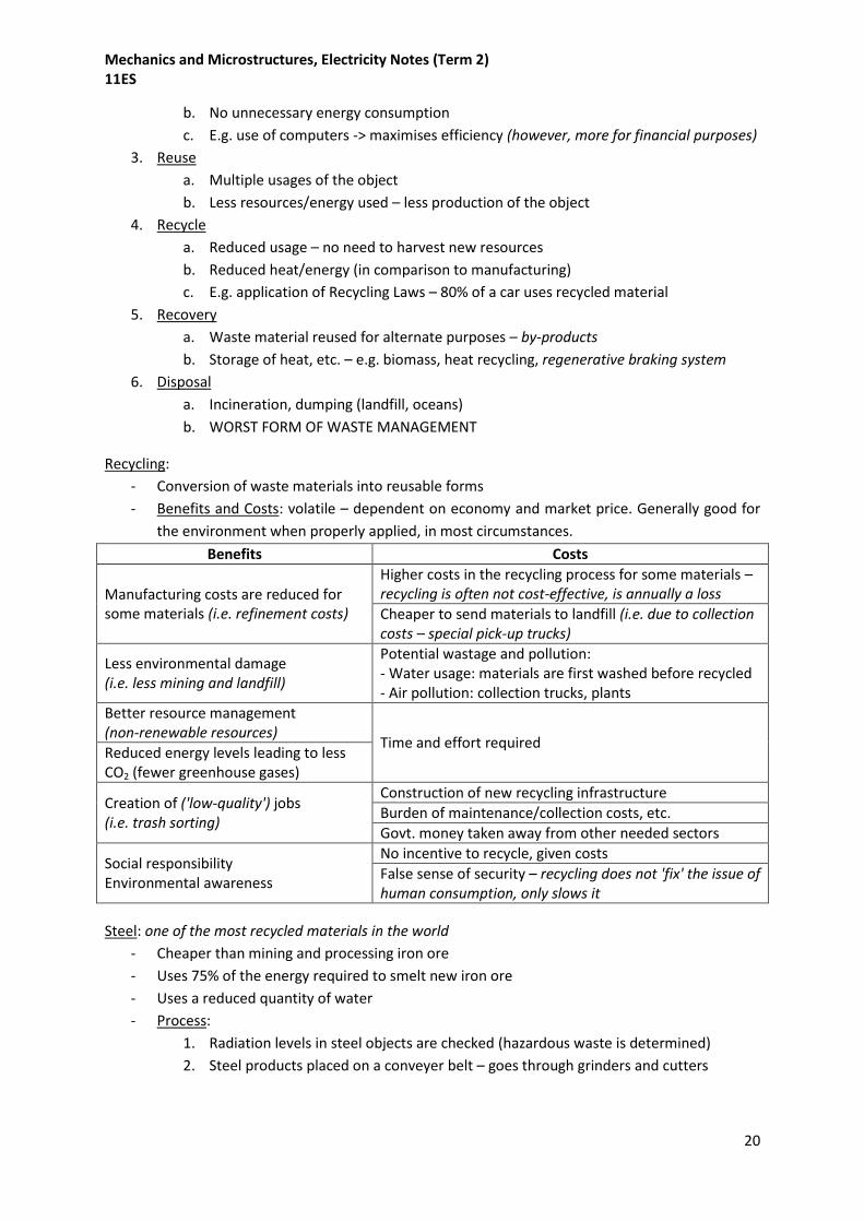
Waste Management Hierarchy: progressively more destructive
1. Prevention (manufacturing considerations)
a. Only producing objects or energy consumption, of things you need
2. Minimisation (manufacturing considerations)
a. No over-engineer or create excessive waste material
Mechanics and Microstructures, Electricity Notes (Term 2) 11ES
20
b. No unnecessary energy consumption
c. E.g. use of computers -> maximises efficiency (however, more for financial purposes)
3. Reuse
a. Multiple usages of the object
b. Less resources/energy used – less production of the object
4. Recycle
a. Reduced usage – no need to harvest new resources
b. Reduced heat/energy (in comparison to manufacturing)
c. E.g. application of Recycling Laws – 80% of a car uses recycled material
5. Recovery
a. Waste material reused for alternate purposes – by-products
b. Storage of heat, etc. – e.g. biomass, heat recycling, regenerative braking system
6. Disposal
a. Incineration, dumping (landfill, oceans)
b. WORST FORM OF WASTE MANAGEMENT
Recycling:
- Conversion of waste materials into reusable forms
- Benefits and Costs: volatile – dependent on economy and market price. Generally good for
the environment when properly applied, in most circumstances.
Benefits Costs
Manufacturing costs are reduced for some materials (i.e. refinement costs)
Higher costs in the recycling process for some materials – recycling is often not cost-effective, is annually a loss
Cheaper to send materials to landfill (i.e. due to collection costs – special pick-up trucks)
Less environmental damage (i.e. less mining and landfill)
Potential wastage and pollution: - Water usage: materials are first washed before recycled - Air pollution: collection trucks, plants
Better resource management (non-renewable resources)
Time and effort required Reduced energy levels leading to less CO2 (fewer greenhouse gases)
Creation of ('low-quality') jobs (i.e. trash sorting)
Construction of new recycling infrastructure
Burden of maintenance/collection costs, etc.
Govt. money taken away from other needed sectors
Social responsibility Environmental awareness
No incentive to recycle, given costs
False sense of security – recycling does not 'fix' the issue of human consumption, only slows it
Steel: one of the most recycled materials in the world
- Cheaper than mining and processing iron ore
- Uses 75% of the energy required to smelt new iron ore
- Uses a reduced quantity of water
- Process:
1. Radiation levels in steel objects are checked (hazardous waste is determined)
2. Steel products placed on a conveyer belt – goes through grinders and cutters

Mechanics and Microstructures, Electricity Notes (Term 2) 11ES
21
3. Resized materials are sorted: a magnetic drum pulls ferrous objects over and across
a collection bin for non-ferrous objects
4. Ferrous objects are sorted: non-ferrous materials like copper/aluminium may have
made it across
5. The steel is smelted in a furnace to be remelted and reforged into a new product
(furnace can be located at a different facility to the sorting process)
Aluminium: commonly recycled
- Cheaper and lower energy consumption, in comparison to manufacturing via electrolysis
o 5% energy consumption in comparison
- Process: (aluminium cans)
1. Similar process to steel: conveyer belt, magnetism, cutters
2. Aluminium pieces are cleaned chemically/mechanically, to reduce oxidation losses
when it is melted and exposed to oxygen
3. Impurities are removed from liquid aluminium:
a. Solids (dross – found floating on the molten metal after oxidisation)
b. Dissolved hydrogen (from degasification)
4. Radiation is tested
5. Aluminium processed in ingots, slabs, etc.
Brass: copper and zinc
- 90-100% of brass is recycled: new brass production is considered costly and a waste of raw
materials
- Process: again similar to previous processes
Plastics (only thermoplastics):
- Limitations:
o Recycled plastics are never re-used for their previous purpose (i.e. beverage
containers), recycled to a plastic chair)
o Limited no. of cycles if additives (dyes, fillers) are progressively added in each cycle
- Process:
1. Recycling plant: plastics are sorted according to categorisation (resin identification
code: 1-7 within a triangle)
2. Plastic is washed/cleaned to remove paper labels, adhesive, impurities
3. Conveyer belts, into hoppers – shreds the plastic into small particles
4. Particles are chemically tested and labelled to exact specifications
5. Pellets are formed via extrusion of the particles

Mechanics and Microstructures, Electricity Notes (Term 2) 11ES
22
Rubber: a type of polymer (i.e. it is a chain of monomers)
- Recycled rubber costs ½ that of natural/synthetic rubber
- Can possess better properties than virgin (non-recycled) rubber
- Process:
o Pure rubber can be recycled through being remelted – e.g. rubber bands
Process is complicated and difficult – expensive
Pure rubber breaks down in exposure to sunlight and air (little presence in
landfill)
o Vulcanised rubber (e.g. car tyres) cannot be truly recycled, only down-cycled and
reused in lower value products (e.g. towards improving asphalt or playground
bedding properties).
Vulcanised rubber has a slow decomposition process (large presence in
landfill)
Note: vulcanising is a process of strengthening rubber by adding sulphur to
link the polymer chains into a stronger matrix
- Car tyres: abundant in landfill, slow decomposition process. Recycling reduces it as an
environmental hazard.
- Process of 'recycling' car tyres:
o Tyre cracking: tyres are made brittle at a low temperature and then cracked to
separate the rubber from other components (e.g. steel wire, nylon fibre)
o Recovered rubber is used as part of a mixture in bitumen – increases high
temperature resistance on roads to prevent it melting (e.g. useful in hot climates)
Engineering Electricity/Electronics
Electricity: the flow of electrons (electric charge) through a system
Potential Difference: 'E', measured in volts (V)
- A measure of electrical pressure (low to high electrical potential energy) between two
points, which causes the flow of current
- Voltage: electric potential energy per unit charge => V = E/q = energy/coulomb
- Also known as voltage or electromotive force
o EMF: voltage generated by the battery. Not a true force – not measured in newtons
o Electrons are not pushed to moving – they move on their own accord
Current: 'I', measured in amperes (A)
- A measure of the rate of the flow of charge per second => I = q/t = charge/time
- Conventional current flow: movement of positive charge (+ve to –ve)
- Electron flow: movement of negative charge, i.e. electrons (-ve to +ve)
o Conventional current flow is incorrect in an electrical current. It is retained today for
historical reasons (to not add confusion to a century of work) and because the
movement of positive charge is possible in other field, e.g. in plasma
- Electron movement: basically the electrons shuffle back and forth, rather than flow through
a wire like water flowing through a pipe [?]
o Electrons flow to satisfy conditions of electric and magnetic fields, obeying
Maxwell's equations

Mechanics and Microstructures, Electricity Notes (Term 2) 11ES
23
o Current can be considered like water flowing through a pipe; electrons cannot.
When energy is added, electrons will move respective of their orbit (i.e. from left to
right). It then loses this energy when it comes close to other electrons (negative
polarity), causing the first electron to lose energy and move back while the second
electron gains energy to move forward respective of its limited orbit.
Electrons do not jump from atom to atom – this requires a redox reaction
like as with forming ionic bonds (impossible with the same elements, without
external 'help')
o Ionic compounds cannot do this: electrons are tightly bonded and cannot transfer
energy
- [Questionable content:]
- Drift current: electric current occurring due to an applied electric field (classical answer)
o Free electrons (electron cloud) in a metal (metallic bonding) randomly move back
and forth in all directions within an ion's orbit – no net movement -> no current
o Applying an electric field (moving from +ve to –ve) causes the electron to be
attracted to the higher electric potential energy: it still randomly moves, but the net
force is in one direction, in the opposite direction and opposing the electric field
(called electron drift) to cancel out the effects of the field
Therefore a good low-frequency approximation can be made that the
electric field in a conductor is always zero.
Each electron will move a little bit, but all electrons will move together,
producing a high net current.
o Often termed EMF over a given distance
- 'In current, the positively charged particles called holes move with the electric field, whereas
the negatively charged electrons move against the electric field.' – e.g. in a diode
- It is not fair to ask where a single electron goes – it has no identity separate from the other
electrons
http://answers.yahoo.com/question/index?qid=20060802014855AAdqt4I
http://van.physics.illinois.edu/qa/listing.php?id=3341
Resistance: 'R', in ohms (Ω)
- The ability of a passage to oppose the flow of current
- Most current flows through the path of least resistance (i.e. it is lazy/efficient)
- Determined by length, cross-sectional area, material, and temperature
o Longer wire -> increases resistance (directly proportional)
o Smaller cross-sectional area -> increases resistance (inversely proportional)
- Resistivity: describes how strongly a material opposes current
o Low resistivity -> more conductive
R = resistivity (rho) * length/cross-sectional area
R = ρ * l/a
R = (Ωm) * m/m2
- Temperature: resistance is constant at a given temperature. If the circuit is changed and
temperature remains the same, a linear relationship results (Ohm's Law)

Mechanics and Microstructures, Electricity Notes (Term 2) 11ES
24
Ohm's Law:
Voltage = Current * Resistance
V = IR
- Ohm's Law does not apply when there is a change in temperature
o Non-ohmic relationship: exponential curve, due to temperature increases
- V-I graph: voltage-current axis. Resistance is determined by the gradient (rise/run). R = V/I
Power:
Power = Voltage * Current
P = VI
- Power is measured in watts, and is the energy consumed per second (i.e. energy used in a
second). This can be explained as:
P = VI = (E/q) * (q/t) = E/t
P = E/t
Conductance:
- Measures passage's easiness to pass electrical current through (opposite of resistance)
- The reciprocal of ohmic resistance: G = 1/Rohmic = I/V (application of Ohm's Law)
Conductivity:
- Measures a material's ability to conduct an electrical current (opposite of resistivity)
- Represented as σ (sigma) or κ (kappa, especially in electrical engineering).
- Reciprocal of resistivity, measured in SI unit, siemens per metre (Sm-1)
Circuits: current can be considered akin to water flowing through a pipe(s)
- Series: components one after another
o VT = V1 + V2 + V3 … + Vn
o IT = I1 = I2 = I3 … = In
o RT = R1 + R2 + R3 … + Rn
- Parallel: components in separate branches
o VT = V1 = V2 = V3 … = Vn
o IT = I1 + I2 + I3 … + In
o 1/RT = 1/R1 + 1/R2 + 1/R3 … 1/Rn
Note: ohmic resistance is the reciprocal of
conductance, therefore the result is that there is more
conductance in a parallel circuit (GT = G1 + G2…)
RT (the equivalent resistor) is always less than the

Mechanics and Microstructures, Electricity Notes (Term 2) 11ES
25
smallest resistor in the parallel circuit (because of increased conductance)
Note: R = V/I can be used to measure a resistor in parallel, as V is constant,
and because IT is based off all Rn resistors. DO NOT attempt to find resistance
as a fraction, etc. (it does not work/is too complex)
Components:
- Resistor: a passive two-terminal component that provides electrical ohmic resistance. As a
whole (as part of the entire circuit) it limits current flow. Individually, it lowers voltage
(making a voltage drop/divider).
- Capacitor: temporary stores electric charges. Consists of two separate metallic plates
insulated from one another by a dielectric
o Dielectric: a poor conductor (dynamic electricity) but good supporter of electrostatic
fields (static electricity)
- Transistor: electronic switch/gate or amplifier. When current flows through the middle leg
(Base, or Gate), current is able to flow through the other two legs.
- Diode: restricts current flow to one direction only (i.e. restricts reverse flow of current,
thereby protecting a circuit from 'reverse polarity')
Electrical Safety:
- Electrocution: electric shock
o Introduction of an external source of electricity that affects the body's ability to
send electrical signals through its nerves
Central nervous system: works via electrical impulses, to give instructions to
vital internal organs
o Muscles in response will contract:
Contraction of chest muscles, restricting breathing in the lungs
Heart's rhythmic motion is disrupted by electrical current into fibrillation
(fluttering, irregular heartbeat contractions)
o Heart:
AC (more dangerous): causes the heart to fibrillate
DC: stops the heart. The heart is then easier to start again – this is the
process of defibrillation.
Severity based on frequency of AC: 50Hz is more dangerous as it is close to
the heartbeat pulse rate (standards chosen before it was realised)
Severity based on current strength and exposure:
Current (mA) Severity from strength Severity from time exposure
0-1mA No perception -
1-15mA Pain at entry/exit points Involuntary muscle contractions (throughout the path of current flow)
Death in minutes (if chest muscles are contracted)
100-200mA Fibrillation – potential death No fibrillation if exposed for less than one heart period
200mA+ (Reversible) stopping of the heart Loss of consciousness
Fibrillation if exposure for less than one heart period
o Average resistance of a human body: 2000Ω
Can vary depending on water moisture placed on skin

Mechanics and Microstructures, Electricity Notes (Term 2) 11ES
26
- Overheating:
o Current is more dangerous than voltage – creates more heat, causing burning of
internal organs
o Fires:
Caused by a current overload in a circuit, or from a short circuit
The electrical fire is potentially electrically energised. Using water, foam, or
any other conductive agent causes electrocution in a person. Aside from the
need to use other agents to fight the fire, the process is the same.
CO2
FM-200 (heptafluoropropane)
PKP (dry chemical powder extinguishers)
Baking soda
Classified a 'Class C' fire in the US system, 'Class E' in Australia
- Exposure to electricity:
o Entry and exit points on the body impact on how dangerous electricity is
o Foot-to-foot: debatably least dangerous – no contact with vital organs – least fatal
o Opposite-hand-to-opposite-foot: most dangerous – passes through vital organs
located at the chest region
Electrical Safety Guidelines and Equipment:
- Fuse: a filament (piece of metal wire, i.e. a lead-tin alloy of a low melting point) that melts
when too much current passes through (typically 5A or 10A). For the filament to not be a fire
hazard, it is encased in high-melting-point casing.
o Easily replaceable with another fuse or circuit breaker
- Circuit breaker: manually resettable switches that mechanically turn and lock themselves
'off' if too much current passes.
o Uses an electromagnet – excess current produces enough magnetism to move the
contacts and break the circuit. Broken contacts are held in place by a spring.
- Earthing: household sockets
o Active/live wire: carries in 240V, 50Hz (Australia)
Top-left pin
Colour-coded brown (previously red; changed for colour blindness issues
involving predominately men, who were the technicians)
o Neutral/return wire: 0V, returns current to power grid/station and its earth
Top-right pin
Colour-coded blue (previously black)
o Earth wire: not part of normal circuit
Connects one part of the appliance (not part of the circuit, thus protecting
from loose wires and short circuits) to a metal stake (post) in the ground,
underneath the building complex. Carries excess current to earth.
Bottom pin
Colour-coded green-yellow (previously green) – green and yellow separately
are indistinguishable, together they are noticeably different
- Double insulation: used for appliances that do not require the third pin

Mechanics and Microstructures, Electricity Notes (Term 2) 11ES
27
o The chassis or case is surrounded by a second layer of insulation (rubber, plastic)
o Prevents the user potentially contacting anything live
o Downfall: unable to open the appliance without breaking it
- Residual Current Devices: RCD or safety switch
o Detects any leakage of current to the earth through some other conductor.
o Acts as a switch that turns off the circuit (and current flow) if current in
does not equal current out.
- Australian Electrical Safety Standards:
o Requires that all electrical articles are approved by a regulatory authority
and identified by a valid Electrical Safety Certificate number.
Energy Ratings for Domestic Appliances:
- Energy rating labels contain two main features for rating:
o Comparative energy consumption (in kWh year-1, or kilowatts per year)
o Star rating:
New 2000 system gave the most efficient systems three stars, to allow for
improvements in efficiency by manufacturers
- Useful for reductions in financial and environmental costs
Household Wiring Conditions:
- Multiple no. of currents: each carries a certain limit of current
o Use of a fuse or circuit breaker for each circuit
- Circuits are thus specialised: e.g. separate light outlets and power outputs
o Circuits for lighting, power; along with highly-specialised circuits purely for individual
stove and hot water systems
- Connections in parallel:
o Distributes 240V to each branch
o Switches turning on/off each branch
- The switch is on the active side of the appliance – if it were on the neutral side, current
could still flow through the appliance and cause electric shock
Fundamentals of AC and DC currents:
- DC: direct current
o Current moves at a constant potential – i.e. it moves in one direction only
o Graph: DC is a constant – a horizontal line
- AC: alternating current
o Flow of electrons that alternates back and forth in many cycles per second (Hz)
At one point, the AC will equal 0V. This means that an appliance such as a
light-bulb, using household AC at 50Hz, will flash off 50 times a second –
but this is faster than the human eye can see.
o Graph: sine wave, or in more complex forms – a square wave, sawtooth wave, etc.

Mechanics and Microstructures, Electricity Notes (Term 2) 11ES
28
- Thus, items designed on DC cannot run on AC
- Peak voltage: maximum voltage
o Household voltage: varies between +340V and -340V, with peak voltage at 350V
- Root-mean-square (RMS):
o Finds the value of DC current that is equivalent in its ability to do work (i.e. its
heating effect) –> this determines the 'average' value of fluctuating AC levels
o The average is also called the "mean-square-voltage", in dimensions volt2 (V2). This
means the AC current is squared to obtain a positive value and then square rooted
to find a weighted average (RMS), which is more accurate than a simple average.
o Resultant pattern within root-mean square (its application):
Conversion from AC to RMS: division of Vpeak by sqrt(2) [i.e. * 0.707V]
Conversion from RMS to AC: multiply by sqrt(2) [i.e. * 1.414V]
o E.g. household voltage: -340V to 340V, with an average voltage of 240V RMS. Note
these are approximations.
o Remember: VP to P = 2 * Vpeak
Comparisons between DC and AC
- DC:
o To create an electrical circuit requires (4): a source of EMF, conductors, a load, and a
control method.
o Relation via Ohm's Law: between V (EMF), I and R
o Kirchhoff's Voltage Law:
Sum of all voltages in a DC series circuit = source/applied voltage
VT = EMF
o Kirchhoff's Current Law:
Current entering a point = current existing the same point
Ienter = Iexit

Mechanics and Microstructures, Electricity Notes (Term 2) 11ES
29
- AC:
o Lenz's Law: an induced current in a conductor will form a magnetic field that
opposes the motion of the inducing field.
I.e. the current direction constantly changes; therefore the magnetic field
constantly changes too.
o Due to changing direction of current, there is both EMF and back EMF (essentially
positive and negative voltage)
o Due to changing direction of current, inductors and capacitors have a reactance that
opposed current flow.
XL = inductive reactance (Ω)
Xc = inductive capacitance (Ω)
L = inductance (Henrys (H))
C = capacitance (Farads (F))
o AC therefore has two components that make up impedance.
Total resistance (RT in Ω)
Total impedance (X in Ω)
o Phase: refers to relationship between AC voltage (EMF) and current at a given
moment
o Purely resistive circuit:
All power is used by the circuit (forwards movement)
Voltage and current are in phase
o Purely reactive circuit:
Power returned to voltage source (backwards movement)
Voltage and current are 90° out of phase
Purely inductive: current lags voltage by 90°
Purely capacitive: current leads voltage by 90°
o Usage of power when considering impedance:
Resistance: uses up power
Reactance: returns the remainder of the power to the voltage source
o If AC passes through a diode, it becomes an irregular DC, called CC (continuous
current). The negative cycle of the AC is omitted.
o AC conversion to DC via full wave bridges (four diodes), etc.
Reactance:
XL = 2πfL
Xc = 1 / (2πfC)
Impedance:
Z = sqrt[ (RT)2 + (XL – Xc)
2 ]
- Note that XL and XC do not have to exist, if there are no inductors (L) or capacitors (C) to
begin with. Therefore this equation can be manipulated to consider only XL or XC if the other
component equals zero, i.e. XC = 0 or XL = 0:
Z = sqrt[ (RT)2 + (XL)
2 ]
Z = sqrt[ (RT)2 + (Xc)
2 ]

Mechanics and Microstructures, Electricity Notes (Term 2) 11ES
30
- It is acceptable to have a negative number in the square root. This means impedance
requires the use of imaginary numbers, defined in one of two ways:
i = sqrt(-1)
i2 = 1
Magnetic Induction: or electromagnetic induction
- Generation of current within a conductor via the use of a
changing/fluctuating magnetic field.
o Electric current has a corresponding magnetic field.
- Similarly, electrical current produces a magnetic field (right-hand
grip). Albeit this is very weak, so the wire is coiled into a solenoid,
and if a metal like iron is placed in the core, an electromagnet is
made (the internal magnetism moving from south to north is
greatly amplified).
Basis of electric motors and generators:
- Electric motor: current in coiled wire induces magnetism, and
the field produces a force that rotates the coil. Applies FBI.
- FBI: left hand rule – shows the directions of force (F), magnetic
field (B), and current (I).
- Magnetic field strength or magnetic-flux density is measured in
the SI unit tesla (T). The strongest magnets encountered can be
over 5 T.
AC electric motor:
- Constitutes 90% of electric motors
- They are safe, simple, robust, cheap
- No need to use a permanent magnet – longer lifespan
Induction Motor: a type of brushless AC motor
1. Coil is wound in such a way around a metal stator – forms a circular cage of electromagnets.
Each of the opposite ends of the circle is a north and south pole.
2. The rotor is a cylindrical electromagnet with distinct opposite polarities.
3. The interaction of these fields creates a force that causes the motor to rotate (torque).
4. AC current means that the polarities of the coil are constantly swapping, causing the motor
to continuously rotate in one direction.
- Types of Induction Motors:

Mechanics and Microstructures, Electricity Notes (Term 2) 11ES
31
o Squirrel Cage: used in fans, refrigerators, some heaters
A stator of copper/aluminium bars
A rotor of laminated steel with aluminium/copper conductors mounted into
slots
Reluctance Motor: a type of AC motor
- Stator and rotor have projecting poles, but no permanent magnets or windings
- Opposite pairs of poles are switched on and off in sequential order, in phases
o E.g. 'A' and 'a' are turned on, then off, and followed by 'B' and 'b'
Types of DC Motors:
Shunt wound Constant speed Low starting torque (not used in situations involving frequent starting/stopping) No runaway under no-load situations
Series Excellent torque at slow speeds High speed under a light load Requires a regulator to prevent runaway
Compound Good starting torque No runaway under no-load situations
Brushless Use of an electric commutator instead of brushes to sense rotor position Greatly reduced wear (from a lack of brushes)
- Runaway: when a motor goes out of control, running at continuously higher RPM until it
destroys itself from mechanical failure, etc.
Types of AC Motors:
Synchronous Similar to an induction motor Rotor travels at the same speed as the rotating magnetic field (unlike an induction motor, the magnetic field of the rotor is not induced)
Brushless Similar to DC brushless motors; but powered by AC Uses a commuter – less likely to fall out of synchronisation under heavy load (in comparison to a synchronous motor)
Induction
Squirrel cage: - Very low torque on start-up - Requires special starting methods when under a load - Can spin in the wrong direction upon starting – occasionally requires an
initial impulse by a heavy copper strip to imbalance one side
Reluctance Robust Good efficiency
Comparison of Electric Motors:
- All motors must have a connection to the rotor to cause the
rotor to spin, i.e. using a brush.
o Brush: a device that conducts current between
stationary wires and moving parts. They function
SIMILAR to paintbrush bristles.
Cheap, low-tech in comparison to using semiconductor devices
- DC motor: requires a split ring commutator that artificially reverses current at appropriate
points to prevent the coil moving back and forth and to instead rotate in one direction

Mechanics and Microstructures, Electricity Notes (Term 2) 11ES
32
- AC motor: no need for a commutator – current reverses naturally
o The current is in phase with the rotor – produces a synchronous motor
http://www.elliottelectronicsupply.com/symbols

Mechanics and Microstructures, Electricity Notes (Term 2) 11ES
33