xw brm td opman r410 (20141208) - sutter instrument making electrical connections, ensure that the...
TRANSCRIPT

Sutter Instrument Company
One Digital Drive Novato, CA 94949
Voice: 415-883-0128 Web: www.sutter.com Fax: 415-883-0572 Email: [email protected]
XenoWorks™ BRM Motorized Micromanipulator
System (TouchDeclutch)
Operation Manual Rev. 4.10 ( 20141208)

XENOWORKS MICROMANIPULATOR SYSTEM (TOUCHDECLUTCH) OPERATION MANUAL – REV. 4.10 (20141208)
ii
Copyright © 2014 Sutter Instrument Company. All Rights Reserved.
XenoWorks™ is a trademark of Sutter Instrument Company.

XENOWORKS MICROMANIPULATOR SYSTEM (TOUCHDECLUTCH) OPERATION MANUAL – REV. 4.10 (20141208)
iii
DISCLAIMER
The XenoWorks BRM Micromanipulator is designed for the specific use of moving
micropipettes in three-dimensional space in increments of micrometers into and out of an
optical pathway of a microscope and no other use is recommended.
This instrument is designed for use in a laboratory environment. It is not intended for use,
nor should it be used, in human experimentation or applied to humans in any way. This is
not a medical device.
Do not open or attempt to repair the instrument. Extreme heat and high voltages are
present and could cause injury.
Do not allow unauthorized and/or untrained operative to use this device.
Any misuse will be the sole responsibility of the user/owner and Sutter Instrument Company
assumes no implied or inferred liability for direct or consequential damages from this
instrument if it is operated or used in any way other than for which it is designed.
SAFETY WARNINGS AND PRECAUTIONS
Electrical
� Operate the XenoWorks BRM using 110-120 V AC, 60 Hz, or 220-240 V AC., 50 Hz line
voltage. This instrument is designed for connection to a standard laboratory power outlet
(Overvoltage Category II), and because it is a microprocessor--controlled device, it should
be accorded the same system wiring precautions as any 'computer type' system. A surge
protector and power regulator are recommended.
� Fuse Replacement: Replace fuse only with the same type and rating as indicated in
the following table.
Fuse
(Type: Time Delay, 5mm x 20mm, glass tube)
Mains Voltage Setting
Rating Manufacturer Examples
“110” (100 – 120 VAC) 2A, 250V (Time
Delay)
Bussmann: GMC-2A, GMC-2-R (RoHS),
GDC-2A, or S506-2A (RoHS)
Littelfuse: 239 002 or 239.002.P (RoHS)
“220” (200 – 240 VAC) T1.0A, 250V Bussmann: GDC-1A or S506-1A (RoHS)
Littelfuse: 218 001 or 218 001.P (RoHS)
A spare fuse is located in the power input module. Please refer to the fuse-replacement
appendix for more details on fuse ratings and for instructions on how to change the fuse.
Avoiding Electrical Shock and Fire-related Injury
� Always use the grounded power supply cord set provided to connect the system to a
grounded outlet (3-prong). This is required to protect you from injury in the event that
an electrical hazard occurs.
� Do not disassemble the system. Refer servicing to qualified personnel.

XENOWORKS MICROMANIPULATOR SYSTEM (TOUCHDECLUTCH) OPERATION MANUAL – REV. 4.10 (20141208)
iv
� To prevent fire or shock hazard do not expose the unit to rain or moisture.
Electromagnetic Interference
To comply with FDA and CE electromagnetic immunity and interference standards; and to
reduce the electromagnetic coupling between this and other equipment in your lab always
use the type and length of interconnect cables provided with the unit for the interconnection
of the controller with the manipulator mechanical and with the joystick (see the
TECHNICAL SPECIFICATIONS appendix for more details).
Operational
Failure to comply with any of the following precautions may damage this device.
� This instrument is designed for operation in a laboratory environment (Pollution Degree
I) that is free from mechanical vibrations, electrical noise and transients.
� This unit is not designed for operation at altitudes above 2000 meters nor was it tested
for safety above 2000 meters.
� Before making electrical connections, ensure that the instrument is switched off.
� DO NOT CONNECT OR DISCONNECT THE CABLES BETWEEN THE
CONTROLLER AND THE MECHANICAL UNITS WHILE POWER IS ON.
Please allow at least 20 seconds after turning the unit off before disconnecting the
mechanical units. Failure to do this may result in damage to the electronics.
� Operate this instrument only according to the instructions included in this manual.
� Do not operate if there is any obvious damage to any part of the instrument.
� Operate only in a location where there is a free flow of fresh air on all sides.
NEVER ALLOW THE FREE FLOW OF AIR TO BE RESTRICTED.
� Do not operate this instrument near flammable materials. The use of any hazardous
materials with this instrument is not recommended and if undertaken is done so at the
users’ own risk.
� Do not attempt to operate the instrument with the manipulator shipping screws in
place - severe motor damage may result.
� Do not operate if there is any obvious damage to any part of the instrument. Do not
attempt to operate the instrument with the manipulator shipping screws in place - severe
motor damage may result. When transporting the mechanical manipulator, be sure to
install the shipping screws supplied in their correct locations. Failure to do this may
result in damage to the motors.
� Never touch any part of the micromanipulator electromechanical device while it is in
operation and moving. Doing so can result in physical injury (e.g., fingers can be caught
and pinched between the moving parts of the micromanipulator).

XENOWORKS MICROMANIPULATOR SYSTEM (TOUCHDECLUTCH) OPERATION MANUAL – REV. 4.10 (20141208)
v
� As with all microinjection devices, sharp micropipettes can fly out of their holder
unexpectedly. Always take precautions to prevent this from happening. Never loosen the
micropipette holder chuck when the tubing is pressurized, and never point micropipette
holders at yourself or others. Always wear safety glasses when using sharp glass
micropipettes with pressure microinjectors.
� Do not handle the manipulator mechanical while the power is on, and take care to
ensure no cables pass close to the mechanical manipulator.
� Sutter Instrument recommends that the operator touch the microscope equipment
base (to discharge any static electricity) prior to using the XenoWorks BRM
Micromanipulator system.
Other
� Use this instrument only for microinjection purposes in conjunction with the procedures
and guidelines in this manual.
� Retain the original packaging for future transport of the instrument.
� Some applications, such as piezo-impact microinjection call for the use of mercury in the
micropipette tip. The use of any hazardous materials with any Sutter Instrument’s
instrument is not recommended and if undertaken is done so at the users’ own risk.
� When transporting the mechanical manipulator, be sure to install the shipping screws
supplied in their correct locations. Failure to do this may result in damage to the motors.
� This instrument contains no user-serviceable components — do not open the instrument
casing. This instrument should be serviced and repaired only by Sutter Instrument or an
authorized Sutter Instrument servicing agent.
� Sutter Instrument reserves the right to change specifications without prior notice.
� This device is intended only for research purposes.
� Do not carry the joystick by its joystick paddle, since damage may result.
Handling Micropipettes
Failure to comply with any of the following precautions may result in injury to the users
of this device as well as those working in the general area near the device.
� The micropipettes used with this instrument are very sharp and relatively fragile.
Contact with the pulled micropipette tips, therefore, should be avoided to prevent
accidentally impaling yourself.
� Always dispose of micropipettes by placing them into a well-marked, spill-proof “sharps”
container.

XENOWORKS MICROMANIPULATOR SYSTEM (TOUCHDECLUTCH) OPERATION MANUAL – REV. 4.10 (20141208)
vi
(This page intentionally left blank.)

XENOWORKS MICROMANIPULATOR SYSTEM (TOUCHDECLUTCH) OPERATION MANUAL – REV. 4.10 (20141208)
vii
TABLE OF CONTENTS
DISCLAIMER ......................................................................................................................................iii
SAFETY WARNINGS AND PRECAUTIONS...................................................................................iii Electrical .................................................................................................................................................iii Avoiding Electrical Shock and Fire-related Injury.............................................................................iii Electromagnetic Interference...............................................................................................................iv Operational .............................................................................................................................................iv Other.........................................................................................................................................................v Handling Micropipettes..........................................................................................................................v
1. GENERAL INFORMATION ...........................................................................................................1 1.1 Introduction.......................................................................................................................................1 1.2 About This Manual...........................................................................................................................1 1.3 Technical Support.............................................................................................................................1 1.4 Product Description..........................................................................................................................1
1.4.1 Packing List ................................................................................................................................1 1.4.2 Joystick Controls and Features ................................................................................................2
1.4.2.1 X- and Y-Axis Control .........................................................................................................3 1.4.2.2 Y-Axis On/Off.......................................................................................................................4 1.4.2.3 Z-Axis Control......................................................................................................................4 1.4.2.4 Joystick Declutch Mechanism............................................................................................4 1.4.2.5 Height Adjustment..............................................................................................................4 1.4.2.6 Joystick Tension Ring.........................................................................................................5 1.4.2.7 ‘Work’ Position ....................................................................................................................5 1.4.2.8 ‘Home’ Position ...................................................................................................................5 1.4.2.9 Speed.....................................................................................................................................5 1.4.2.10 ‘Z-floor’ ...............................................................................................................................5 1.4.2.11 Micropipette Holder Clamp..............................................................................................5 1.4.2.12 Swing Gate .........................................................................................................................6
1.4.3 Additional Features and Functions..........................................................................................6 1.4.3.1 ‘Setup’...................................................................................................................................6 1.4.3.2 Axis Polarity.........................................................................................................................7
2. INSTALLATION ..............................................................................................................................9
3. OPERATING INSTRUCTIONS....................................................................................................13 3.1 General.............................................................................................................................................13
3.1.1 Moving the Micropipette with the Joystick...........................................................................13 3.1.2 Centering the Micropipette with Respect to the Joystick....................................................13 3.1.3 Setting the Angle of Approach of the Micropipette..............................................................14
3.1.3.1 Microinjection Chamber ...................................................................................................14 3.1.3.2 Applications and Suggested Setups.................................................................................14 3.1.3.3 Micropipette Type .............................................................................................................16 3.1.3.4 Working Distance ..............................................................................................................16 3.1.3.5 Piezo Impact Drive............................................................................................................16
3.1.4 Memorizing the ‘Work’ Position ............................................................................................16 3.1.5 Using the ‘Home’ Function.....................................................................................................16

XENOWORKS MICROMANIPULATOR SYSTEM (TOUCHDECLUTCH) OPERATION MANUAL – REV. 4.10 (20141208)
viii
3.1.6 Cleaning the Micropipette.......................................................................................................17 3.1.7 Changing the Working Range of Movement.........................................................................17
3.1.7.1 Setting a ‘Z-Floor’..............................................................................................................17 3.1.8 Exchanging the Micropipette..................................................................................................18
3.2 Starting a Microinjection Session..................................................................................................18 3.2.1 Setting up the Microscope.......................................................................................................18 3.2.2 Setting up the Micromanipulator...........................................................................................19
4. MAINTENANCE............................................................................................................................21 4.1 General.............................................................................................................................................21 4.2 Troubleshooting..............................................................................................................................21 4.3 Transporting the Micromanipulator ............................................................................................25
APPENDIX A. LIMITED WARRANTY............................................................................................27
APPENDIX B. ACCESSORIES .........................................................................................................29 Extensions..............................................................................................................................................29 Rotating Base.........................................................................................................................................29 Mounts ...................................................................................................................................................29 Adapters .................................................................................................................................................29 Holders ...................................................................................................................................................29
APPENDIX C. FUSE REPLACEMENT...........................................................................................31
APPENDIX D. TECHNICAL SPECIFICATIONS...........................................................................33
INDEX.................................................................................................................................................37
TABLE OF FIGURES
Figure 1-1. Components of the XenoWorks micromanipulator. ...........................................................2
Figure 1-2. Joystick. ...................................................................................................................................3
Figure 1-3. The rear panel of the joystick. ...............................................................................................3
Figure 1-4. Joystick height adjustment....................................................................................................4
Figure 1-5. Manipulator Mechanical. .......................................................................................................6
Figure 1-6. Close up of axis polarity switches..........................................................................................7
Figure 2-1. Mounting the right-handed manipulator to the far left corner of the adapter plate. .....9
Figure 2-2. Engaging the manipulator base plate in the microscope adaptor. ..................................10
Figure 3-1. Location of LED and declutch touch band.........................................................................13
Figure 3-2. Micropipette alignment controls. ........................................................................................14
Figure 3-3 (a and b). Suggested approach for suspended cells with angled micropipettes (ICSI,
Stem Cell, Nuclear Transfer). ...............................................................................................15
Figure 3-4 (a and b). Suggested approach for suspended cells with straight micropipettes
(Pronuclear Injection). ...........................................................................................................15
Figure 3-5 (a and b). Suggested approach for adherent cells rand straight pipettes. .......................15

XENOWORKS MICROMANIPULATOR SYSTEM (TOUCHDECLUTCH) OPERATION MANUAL – REV. 4.10 (20141208)
ix
Figure C-1. Fuse replacement. ................................................................................................................31
TABLE OF TABLES
Table A-1. Mains fuse type and ratings.................................................................................................11
Table C-1. Mains fuse type and ratings.................................................................................................31
Table D-1. Speed settings and ranges of movement.............................................................................33
Table D-2. Mains fuse type and ratings. ...............................................................................................34
Table D-3. XenoWorks BRM Controller cables and receptacles/connectors......................................34

XENOWORKS MICROMANIPULATOR SYSTEM (TOUCHDECLUTCH) OPERATION MANUAL – REV. 4.10 (20141208)
x
(This page intentionally left blank.)

XENOWORKS MICROMANIPULATOR SYSTEM (TOUCHDECLUTCH) OPERATION MANUAL – REV. 4.10 (20141208)
1
1. GENERAL INFORMATION
1.1 Introduction
1.2 About This Manual
The XenoWorks Micromanipulator is a manipulator system comprised of three basic parts:
the controller (BRM), manipulator mechanical (MP-285/M), and joystick.
In the next, few pages you will find a product description to help you become acquainted with
operation, followed by installation instructions, and then detailed operating instructions.
Please take the time to read these instructions to assure the safe and proper use of this
instrument.
This manual is continually being updated. If you encounter any areas you feel should be
covered in expanded detail we would like to hear from you. Please contact our Technical
Support staff with your suggestions (415-883-0128 or [email protected]).
1.3 Technical Support
Unlimited technical support is provided by Sutter Instrument Company at no charge to our
customers. Our technical support staff is available between the hours of 8:00 AM and 5:00
PM (Pacific Time) at (415) 883-0128. You may also E-mail your queries to [email protected].
1.4 Product Description
NOTE: Unless otherwise noted, all references to the manipulator mechanical are for the
right-handed version.
1.4.1 Packing List
The XenoWorks™ Micromanipulator is shipped with the following components:
1. Manipulator mechanical
2. Controller
3. Joystick
4. Manipulator mechanical base plate
5. Mains power cord
6. Cable for connecting the manipulator mechanical with the controller
7. Cable for connecting joystick with the controller
8. Instruction manual
9. Manipulator mechanical mounting screws (4)
10. Hex key (for manipulator mechanical mounting screws)
If any items are missing or appear damaged, contact Sutter Instrument or your dealer/rep
immediately.

XENOWORKS MICROMANIPULATOR SYSTEM (TOUCHDECLUTCH) OPERATION MANUAL – REV. 4.10 (20141208)
2
Figure 1-1. Components of the XenoWorks micromanipulator.
1.4.2 Joystick Controls and Features
The user interface of the XenoWorks™ Micromanipulator is a three-axis joystick. When the
micromanipulator is installed correctly, the joystick oriented appropriately on the working
surface, and the default axis polarity settings used (see “Axis Polarity”), a displacement of the
joystick to the left, for example, will result in concomitant movement of the
micromanipulator to the left. The movement of the micromanipulator is directly proportional
to the movement of the joystick, however the movement reduction ratio between the joystick
and the mechanical can be varied (see “Range” below).

XENOWORKS MICROMANIPULATOR SYSTEM (TOUCHDECLUTCH) OPERATION MANUAL – REV. 4.10 (20141208)
3
Figure 1-2. Joystick.
Figure 1-3. The rear panel of the joystick.
1.4.2.1 X- and Y-Axis Control
Movements of the micromanipulator in the X- and Y-axes are achieved by moving the joystick
left and right, and forward and backward, respectively (the switches for establishing axis
polarity for right- and left-handed manipulator mechanicals are located on the back of the
joystick).

XENOWORKS MICROMANIPULATOR SYSTEM (TOUCHDECLUTCH) OPERATION MANUAL – REV. 4.10 (20141208)
4
1.4.2.2 Y-Axis On/Off
The Y-axis can be turned off to produce pure X-axis travel. This results in a mode that may be
preferred for difficult injections/transfers, or when the cell or egg is more sensitive to the
withdrawal of the pipette.
1.4.2.3 Z-Axis Control
Movement of the micromanipulator in the Z-axis (vertical) is achieved by rotating the control
on the end of the joystick. Looking down on the joystick from above, and using the default
axis settings, a rotation of the Z-control in a clockwise direction will cause the
micromanipulator to move downwards. A counterclockwise rotation will result in an upward
movement of the micromanipulator.
1.4.2.4 Joystick Declutch Mechanism
The electronic link between the joystick and the manipulator mechanical can be disconnected
temporarily in order to reposition the joystick without affecting the position of the
micropipette. This declutch function is achieved by touching the joystick just above the
rubber handgrip - the X and Y movement will remain deactivated for as long as your finger is
touching the band. The link is reestablished by releasing the touchpad. See Operating
Instructions for more details on how to use the declutch.
1.4.2.5 Height Adjustment
To maintain good ergonomics and operator comfort, the height of the joystick can be
adjusted, as shown in the figure below. The bottom of the joystick can be placed anywhere
from zero to 45 mm above the black hand-rest pad. The adjustment is made by first loosening
the black locking knob located on the front of the joystick column. Move the joystick
assembly up and down along its vertical track until a comfortable position is achieved, and
then lock the position by tightening the locking knob.
Figure 1-4. Joystick height adjustment.
1.4.2.6 Joystick Tension Ring
There is a friction mechanism in the top of the joystick assembly allowing the X-Y movement
of the joystick to be adjusted for comfort and feel. The friction is reduced by rotating the
black dial clockwise (looking down from above) and increased by rotating counterclockwise.

XENOWORKS MICROMANIPULATOR SYSTEM (TOUCHDECLUTCH) OPERATION MANUAL – REV. 4.10 (20141208)
5
Although there is no recommended setting for this friction, it should be noted that if there is
no friction at all, the joystick would always fall to the center position under gravity, which
may not be desirable. Similarly, if the friction is set too tightly, the joystick may become too
stiff to use or may be locked in place and could be damaged if the dial is tightened further.
With a little practice, a suitable tension setting can be established.
1.4.2.7 ‘Work’ Position
The users’ ‘Work’ position can be designated as any position within the range of travel of the
micromanipulator. It is used primarily to ensure that the micropipette tip is not
inadvertently lost from the microscope field of view. It is recommended that the ‘Work’
position is refreshed at regular intervals during the course of an injection experiment. The
micropipette can be returned to the last position memorized by briefly touching the ‘Work’
key (See Operating Instructions).
1.4.2.8 ‘Home’ Position
Activation of the ‘Home’ function moves the mechanical to its outermost and uppermost
position, with respect to the microscope. The ‘Home’ position of a right-hand
micromanipulator will be all the way up and to the right and the ‘Home’ position of a left-
hand micromanipulator will be all the way up and to the left. It is for this reason that a right-
hand micromanipulator should not be used on the left side of the microscope and vice-versa.
The ‘Home’ position is a factory preset and cannot be re-configured. See Operating
Instructions for details.
1.4.2.9 Speed
The speed of the micromanipulator can be adjusted to accommodate different microscope
magnifications and the differing needs of operators and applications. There are six speed
settings corresponding to six different sensitivities of micromanipulator movement. See
Operating Instructions on how to set the desired movement range. Speed settings 1 and 2 are
good for locating pipette into field of view. Speeds 3, 4, and 5 are ideal for micromanipulation
and microinjection.
1.4.2.10 ‘Z-floor’
The ‘Z-floor’ is a function which allows the user to define a lower limit (or “floor”) of the Z-
axis travel of the micromanipulator. In practice, it is used to protect a micropipette from
being broken by preventing the user from crashing the micropipette into the bottom of the
microinjection chamber. The ‘Z-floor’ is described in more detail in the Operating
Instructions section.
1.4.2.11 Micropipette Holder Clamp
The micropipette holder clamp arrangement on the front of the mechanical is designed to
allow many different micropipette types to be used with the maximum stability possible. The
clamp can be adjusted for height, reach and angle of attack. See Operating Instructions for
details on setting the micropipette holder clamp for the optimum angle of attack of the
micropipette.

XENOWORKS MICROMANIPULATOR SYSTEM (TOUCHDECLUTCH) OPERATION MANUAL – REV. 4.10 (20141208)
6
1.4.2.12 Swing Gate
The swing gate on the front of the mechanical allows the micropipette to be swung out
toward the front of the microscope for better access when changing micropipettes. The gate
can be released by loosening the fixing screw. The screw should be tightened fully during use.
Figure 1-5. Manipulator Mechanical.
1.4.3 Additional Features and Functions
1.4.3.1 ‘Setup’
When the micropipette is aligned at the beginning of an experiment, the tip should be located
in the center of the microscope’s field of view and there should be as much movement range
as possible in both directions in each axis, X, Y and Z. The ‘Setup’ function has been designed
to easily achieve this and thus protect the user from inadvertently running out of motor
travel during an experiment. By following the instructions included in this manual, use of
the ‘Setup’ function will position each of the three axis motors in an optimal position to begin
working.
CAUTION: Use the Setup function only when there is no pipette and holder in the manipulator.
The ‘Setup’ function should only be activated when there is sufficient space available around
the mechanical. Activating the ‘Setup’ function when the manipulator mechanical is too close
to a microscope component such as the condenser, may result in damage to the motor or the
microscope. Refer to Installation Procedure for details on the use of the ‘Setup’ function
during installation and Operating Instructions for details on routine use.

XENOWORKS MICROMANIPULATOR SYSTEM (TOUCHDECLUTCH) OPERATION MANUAL – REV. 4.10 (20141208)
7
1.4.3.2 Axis Polarity
Occasionally, it may be desirable to reverse the direction of one, two or all three motors so
that the movement of the joystick results in movement of the corresponding manipulator
mechanical in the opposite direction. An example of this would be the use of the manipulator
with an upright microscope where the image is inverted.
The axis polarity controls are located on the rear of the joystick column.
Each DIP-switch control affects one axis; switch 1 reverses the X-axis, switch 2 reverses the
Y-axis, and switch 3 reverses the Z-axis. The figure above illustrates the default axis polarity
settings for a left-hand (left image) and right-hand (right image) micromanipulator. Axis
polarities can be changed without having to power down the micromanipulator.
Figure 1-6. Close up of axis polarity switches.

XENOWORKS MICROMANIPULATOR SYSTEM (TOUCHDECLUTCH) OPERATION MANUAL – REV. 4.10 (20141208)
8
(This page intentionally left blank.)

XENOWORKS MICROMANIPULATOR SYSTEM (TOUCHDECLUTCH) OPERATION MANUAL – REV. 4.10 (20141208)
9
2. INSTALLATION
The directions below describe the installation procedure common to both left- and right-
handed micromanipulators, although the figures illustrate a right-hand micromanipulator (a
left hand micromanipulator would be illustrated as a mirror image of these figures). It is
extremely important that these installation instructions are followed closely.
1. Unpack and assemble the microscope adapter and attach it firmly to the microscope
according to the instructions included with the adapter.
2. Unpack the mechanical manipulator adapter base plate. The Y-axis slide on the bottom of
the adapter plate can be adjusted so that the mechanical is positioned correctly with
respect to the microscope’s optical axis. Each model microscope will require special Y-axis
slide settings. To determine the appropriate setting for your microscope, refer to the
lookup table contained in the instruction sheet supplied with the microscope adapter.
3. Align the back edge of the slide in the numbered channel with the number in the
instructions that corresponds with the microscope being used. Lock the Y-axis slide
screws firmly with the hex (Allen) key provided.
Figure 2-1. Mounting the right-handed manipulator to the far left corner of the adapter plate.
4. Unpack the manipulator mechanical. Take extra care while handling the mechanical -
before it is mounted on the microscope adapter, it is vulnerable to impacts which can
damage the stepper motors.

XENOWORKS MICROMANIPULATOR SYSTEM (TOUCHDECLUTCH) OPERATION MANUAL – REV. 4.10 (20141208)
10
5. Remove the six (6) shipping screws (indicated by the red stripes)
IMPORTANT: Retain the six (6) shipping screws and keep them with the instrument
packaging in the event that the instrument needs to be shipped to another location.
6. Carefully place the manipulator on the base plate so that the micropipette holder clamp
faces toward the front of the microscope, as shown above for a right-hand
micromanipulator. The two innermost screw holes (closest to the microscope – arrowed)
on the base of the mechanical should be visible. Attach the manipulator to the adapter
plate in the position shown, using the screws and tool provided. Do not use shipping
screws for this purpose - they are too long.
7. Slide the dovetail on the bottom of the adapter plate into the slide of the microscope
adapter (it may be necessary to loosen the locknut on the rear of the microscope adapter).
Do not tighten the locknut at this time.
Figure 2-2. Engaging the manipulator base plate in the microscope adaptor.
8. Unpack the controller cabinet and place it on a shelf or flat surface near the microscope.
9. Power and Voltage Selection: The power entry module on the rear of the controller has a
voltage-select dial that can be set to either “110” (100 – 120) or “220” (200 – 240) VAC.
Ensure that the voltage rating matches your local voltage supply; if not, switch it now.
10. Power Fuse, Ratings, and Selection: The power entry module also contains the fuse. It is
very important that the correct fuse rating is used for the voltage selected, as indicated in
the table below.

XENOWORKS MICROMANIPULATOR SYSTEM (TOUCHDECLUTCH) OPERATION MANUAL – REV. 4.10 (20141208)
11
Table A-1. Mains fuse type and ratings.
Fuse
(Type: Time Delay, 5mm x 20mm, glass tube)
Mains Voltage
Setting
Rating Manufacturer Examples
“110”
(100 – 120
VAC)
2A, 250V
(Time
Delay)
Bussmann: GMC-2A, GMC-2-R (RoHS), GDC-2A, or S506-
2A (RoHS)
Littelfuse: 239 002 or 239.002.P (RoHS)
“220”
(200 – 240
VAC)
T1.0A,
250V
Bussmann: GDC-1A or S506-1A (RoHS)
Littelfuse: 218 001 or 218 001.P (RoHS)
11. Using the remaining two cables, connect the mechanical and joystick to the back panel of
the controller.
12. Set the joystick height adjustment for comfortable use and adjust the joystick tension
ring to achieve a comfortable tightness. Ensure that the joystick is centered (hanging
straight down) and that the entire joystick is oriented with the hand-rest to the front and
the column to the rear.
13. Connect the power cord to the power input module on the rear of the controller cabinet.
14. Plug the instrument into the electrical supply and switch it on. The green LEDs on the
base of the joystick will illuminate and an audible signal will sound to indicate successful
initialization of the instrument.
15. Select the coarse range setting by rotating the speed control knob to the ‘C’ position (see
Operating Instructions for details).
16. Slowly move the joystick INWARD (toward the microscope), until the end of travel is
reached in the X-axis. Use the Declutch if necessary. Take care not to let the mechanical
touch any part of the microscope, particularly the condenser. Ensuring that the
mechanical base plate is in an outer position on the dovetail slide will help prevent this.
17. Now slide the manipulator mechanical base plate inwards until the manipulator is
approximately 5 mm away from the microscope condenser (in the case of inverted
microscopes).
18. Since the manipulator is currently at its innermost position, the dovetail of the
manipulator adapter plate can safely be locked at this position without danger of the
motor running into the microscope condenser during use. Use the locknut on the rear of
the microscope adaptor to lock the manipulator mechanical base plate in place.
19. The remaining (outer) two mounting screws should now be visible on the base of the
mechanical. Use the final two mounting screws to finish attaching the manipulator
mechanical to the base plate.
20. Press the ‘Setup’ button on the rear of the joystick. This will place the motors in the
following positions: X motor – ¾ of total travel from the outermost position, Y motor –
center of travel, Z motor – ¾ of total travel from the uppermost position. Using the
‘Setup’ position as a starting point, the user is less likely to run out of motor travel
during routine use.
The XenoWorks™ Micromanipulator is now set up and ready for use.

XENOWORKS MICROMANIPULATOR SYSTEM (TOUCHDECLUTCH) OPERATION MANUAL – REV. 4.10 (20141208)
12
See the next section for details on how to align a micropipette at the start of an injecting
session.

XENOWORKS MICROMANIPULATOR SYSTEM (TOUCHDECLUTCH) OPERATION MANUAL – REV. 4.10 (20141208)
13
3. OPERATING INSTRUCTIONS
3.1 General
3.1.1 Moving the Micropipette with the Joystick
Once the micromanipulator has been installed correctly, the micropipette should follow the
movement of the joystick. The higher the number on the range control, the smaller the
movement will be for any given deflection of the joystick. When in range settings ‘2’ through
‘5’, the micropipette will follow the movements of the joystick without any delay. Settings ‘C’
and ‘1’ are for coarse positioning only and should not be used for precision
micromanipulation.
3.1.2 Centering the Micropipette with Respect to the Joystick
The Declutch mechanism is used to re-center the joystick with respect to the micropipette
tip. This is useful when the micropipette is at the very edge of the microscope field of view
but the joystick is centered, or when the micropipette is in the center of the field of view, but
the joystick is at the edge of its travel. To center or reposition the joystick without affecting
the micropipette, simply touch the declutch ring/band just above the rubber grip as shown in
the figure. To re-establish movement, remove your finger from the touch-sensitive band. A
red LED lights on top of the joystick whenever the Declutch function is activated.
Figure 3-1. Location of LED and declutch touch band.

XENOWORKS MICROMANIPULATOR SYSTEM (TOUCHDECLUTCH) OPERATION MANUAL – REV. 4.10 (20141208)
14
3.1.3 Setting the Angle of Approach of the Micropipette
The micropipette holder clamp is capable of rotating around its own axis and the movement
can be locked with the thumbscrew (1) shown here. It is also possible to slide the clamp and
lock it in place with a separate thumbscrew (2). The clamp itself is spring-loaded, allowing a
4 mm diameter micropipette holder (not included) to be advanced or retracted easily without
removing it or risk of it falling out inadvertently.
Figure 3-2. Micropipette alignment controls.
These degrees of freedom allow for angles of attack from zero to greater than 45 degrees,
while at the same time allowing the micropipette holder to be clamped at any point along its
length. This accommodates a large number of different micropipettes, angled or straight, and
accessories such as piezo impact drills. When combined with the three fixing patterns on the
top plate of the mounting adapter, and the sliding action of the mounting adapter, the
XenoWorks™ Micromanipulator is capable of accommodating any application on a large
number of microscope platforms.
The following paragraphs describe factors that affect the setting of the micropipette holder.
3.1.3.1 Microinjection Chamber
Some types of microinjection chamber, plastic culture dishes for example, will require a steep
angle of approach, so that the micropipette clears the sides of the dish (up to 45 degrees).
Other chambers, depression slides, for example, can accommodate a much shallower angle of
approach (typically around 10–15 degrees for a depression slide).
3.1.3.2 Applications and Suggested Setups
In general, any application in which suspension cells are to be injected or manipulated
(embryonic stem cell transfer, intracytoplasmic sperm injection, pronuclear zygote injection,
embryo reconstruction) will require two micropipettes (and thus two micromanipulators),
one for holding and one for injecting. In this instance, the micropipette tips must approach
the tissue side-on to prevent the injection micropipette from pushing the tissue off the
holding pipette. When using a deep dish and angled micropipettes, a 35–45 degree angle of
attack is appropriate (shown in the figures on the page opposite). If using a depression slide
and straight micropipettes, an almost flat angle is required as shown in the figures below.

XENOWORKS MICROMANIPULATOR SYSTEM (TOUCHDECLUTCH) OPERATION MANUAL – REV. 4.10 (20141208)
15
Setup for various applications
a. b.
Figure 3-3 (a and b). Suggested approach for suspended cells with angled micropipettes (ICSI, Stem Cell, Nuclear
Transfer).
a. b.
Figure 3-4 (a and b). Suggested approach for suspended cells with straight micropipettes (Pronuclear Injection).
a. b.
Figure 3-5 (a and b). Suggested approach for adherent cells rand straight pipettes.

XENOWORKS MICROMANIPULATOR SYSTEM (TOUCHDECLUTCH) OPERATION MANUAL – REV. 4.10 (20141208)
16
3.1.3.3 Micropipette Type
Some micropipettes (lab-made or purchased ICSI pipettes, for example) are often designed
with an angle close to the tip. This is to allow the micropipette tip to approach the injected
cell from a trajectory parallel to the bottom of the chamber, and to allow the use of a high-
sided dish. Other micropipettes may not have a bend, in which case they must be used with a
flat injection chamber (a depression slide for example) of a low angle of approach.
3.1.3.4 Working Distance
Most microinjection procedures are carried out on an inverted microscope where the
condenser is located above the stage and the objective lenses below. If the microscope was
purchased specifically for microinjection, it was probably supplied with a “long” or “very
long” working distance condenser that should provide adequate space above the stage to set
up the micropipette and accommodate any type of chamber. When setting up the manipulator
adapter plate, the manipulator mechanical and the micropipette holder, carefully observe the
relative positions of the micromanipulator, the microscope stage, and the condenser to avoid
collision by the manipulator.
3.1.3.5 Piezo Impact Drive
For those applications that require the use of a piezo impact drive, the position of the piezo
must be taken into account when aligning the micropipette holder (and also when attaching
the mechanical to the microscope mount). Typically, a piezo device is mounted at the back of
the micropipette holder, and so the holder can be gripped at the very front. A Prime Tech
piezo device can be mounted anywhere along the length of the micropipette holder, either in
front, or behind the micropipette holder clamp.
3.1.4 Memorizing the ‘Work’ Position
This is accomplished by first using the joystick to position the micropipette in the desired
‘Work’ position. Then, press and hold down the ‘Work’ button on the base of the joystick for
approximately three seconds, until a tone is heard. The beep indicates that the position has
been set. A previously set ‘Work’ position can be overwritten with a new position at any time
by repeating this action. The micropipette can be moved to the currently set position by
briefly touching the ‘Work’ key. The movement can be stopped by quickly pressing ‘Work’
again. Pressing the key once more resumes the movement towards the ‘Work’ position. This
process can be repeated until the micropipette reaches the ‘Work’ position. The current
‘Work’ position is preserved in the micromanipulator memory even if it is switched off; it is
advisable to establish a new ‘Work’ position when setting up the position of the micropipette.
3.1.5 Using the ‘Home’ Function
The ‘Home’ function is activated by briefly pressing the yellow ‘Home’ button, the outermost
button of the group of three on the hand-rest of the joystick.
This function is usually used to temporarily remove the micropipette from the injection
chamber (to change dishes, for example), or to exchange micropipettes. Note that a ‘Work’
position must be set (see above) if the micropipette is to be moved back into the position it
was in before the ‘Home’ function was activated. When the ‘Home’ function is activated, the
micropipette will move from its starting position to the ‘Home’ position. This movement can
be halted at any time by briefly pressing ‘Home’ again, or by briefly pressing ‘Work’.
Pressing ‘Home’ once more will resume the movement of the micropipette to the ‘Home’
XENOWORKS MICROMANIPULATOR SYSTEM (TOUCHDECLUTCH) OPERATION MANUAL – REV. 4.10 (20141208)
17
position. Briefly pressing the ‘Work’ key will reverse the direction and move the micropipette
to the ‘Work’ position (In this way, a micropipette can be partially raised out of the injection
chamber and returned, without having to move all the way out to the ‘Home’ position – see
“Cleaning the Micropipette” below). Note that the micropipette tip moves out at
approximately 45°, no matter what its angle of incidence.
3.1.6 Cleaning the Micropipette
The ‘Work’ and ‘Home’ functions can be used together to clean material from the tip of the
micropipette. Record the ‘Work’ position as the center of the field of view, then activate the
‘Home’ function. As soon as the micropipette tip has passed out of the injection medium,
press ‘Home’ again briefly to stop the micropipette movement. By passing the micropipette
through the surface of the injecting medium, debris on the outside of the micropipette tip is
usually cleared. Press ‘Work’ briefly and the micropipette will return to the ‘Work’ position.
3.1.7 Changing the Working Range of Movement
The range of movement of the micropipette can be varied depending on the desired
movement characteristics and the magnifying power of the microscope. The range can be
changed by simply rotating the range control knob to the desired setting. The ranges
available are listed under Specifications.
3.1.7.1 Setting a ‘Z-Floor’
The ‘Z-floor’ is set in the following manner:
1. Locate the tip of the micropipette in the field of view of the microscope.
2. Slowly rotate the Z-axis control clockwise, lowering the micropipette towards the bottom
of the injection chamber, following the micropipette tip down with the microscope’s fine
focus. Use slower speeds (3 – 5) when close to the bottom of the dish.
3. When the micropipette touches the bottom of the injection chamber it will appear to
move inward as it brushes the bottom of the dish. (CAUTION: Sharp micropipettes, such as cell injection micropipettes with high angles of approach, may break if they are pressed too hard against the bottom of the injection chamber.) Raise the micropipette up slightly
so that it just clears of the bottom of the chamber.
4. Press and hold the ‘Z-floor’ key down for about three (3) seconds. A tone will be heard
indicating that it has been set and a green LED will light on the joystick base indicating
that the ‘Z-floor’ is active. The ‘Z-floor’ can be toggled on and off by pressing the key
briefly. When the ‘Z-floor’ is active, the Z-axis will not move any lower than the preset
position, protecting the micropipette from inadvertent crashes. If the micropipette is
moved below the ‘Z-floor’ position when it is inactive, and the ‘Z-floor’ is then activated,
the micropipette will only move upwards when the Z-axis control on the joystick is
rotated. When the ‘Z-floor’ position is reached, normal movement will resume. A new ‘Z-
floor’ can be set at any time to overwrite the previous setting. The ‘Z-floor’ setting is
erased when the micromanipulator is switched off.
CAUTION: If a ‘Work’ position is set below a ‘Z-floor’ limit, the micropipette will move below the ‘Z-floor’ when the ‘Work’ key is pressed.

XENOWORKS MICROMANIPULATOR SYSTEM (TOUCHDECLUTCH) OPERATION MANUAL – REV. 4.10 (20141208)
18
3.1.8 Exchanging the Micropipette
During the course of a microinjection procedure, it may be necessary to exchange
micropipettes. One effective method of doing this is to incorporate the ‘Home’ function in the
following manner:
1. Center the micropipette in the microscope field of view and above the dish by 3 mm, and
press and hold down the ‘Work’ key to memorize the coordinates.
2. Press ‘Home’, and the mechanical will move to the upper and outer limits of travel. The
movement from ‘Work’ to ‘Home’ can be paused at any time by pressing ‘Home’ or ‘Work’
briefly. Movement to ‘Home’ can be resumed by pressing ‘Home’ again briefly.
3. Unlock and open the swing gate to access the top of the micropipette holder.
4. Taking care not to disturb the position of the micropipette holder in its clamp, loosen the
chuck on the front of the micropipette holder and remove and discard the micropipette
safely.
5. Fit a new micropipette into the holder and lock the chuck in place.
6. Return the swing gate to the working position and lock it in place.
7. Press ‘Work’ to move the micropipette above the injection chamber and in the field of
view.
CAUTION: It is important to remember that when activating the ‘Work’ function, the micromanipulator records the position of the micromanipulator motors, not the micropipette tip. Therefore, if a micropipette is being replaced by one that is longer, the micropipette may crash into the bottom of the injection chamber upon returning to ‘Work’ from ‘Home’. Several measures, taken alone or together, can prevent this: When returning to ‘Work’ from ‘Home’, approach the injection chamber with the new micropipette in stages by toggling the ‘Work’ key. Once the micropipette tip is close to the bottom of the injection chamber, use small movements on low speeds with the joystick.
3.2 Starting a Microinjection Session
3.2.1 Setting up the Microscope
1. Locate the correct focal plane for the microinjection chamber in the following manner:
2. Place a representative microinjection dish, chamber or slide on the stage of the
microscope, set the microscope to its lowest possible magnification, and focus on the
uppermost surface of the bottom of the chamber (an effective method is to draw a pen
mark in the center of the chamber to be used, and focus on that). This establishes the
correct microscope focal plane for microinjection.
3. The microinjection chamber can now be removed and, as long as the microscope focus is
not disturbed, the micropipette tip can be manipulated into the optical axis, above the
bottom of the injection chamber.
3.2.2 Setting up the Micromanipulator
1. Remove the micropipette holder (rod) from the clamp of the mechanical.
2. Activate the ‘Setup’ key on the rear of the joystick. This ensures that the motors are in
their optimum positions prior to starting ‘Work’.

XENOWORKS MICROMANIPULATOR SYSTEM (TOUCHDECLUTCH) OPERATION MANUAL – REV. 4.10 (20141208)
19
3. Load a micropipette (appropriate to the chosen application) into the micropipette holder
and install it in the clamp of the mechanical so that the tip of the micropipette is pointing
in and down towards the optical axis of the microscope.
4. Adjust the angle setting of the micropipette clamp on the mechanical so that the angle of
attack of the pipette is appropriate for the chosen application as described in Operating
Instructions.
5. Once an appropriate angle of approach has been set, loosen the micropipette holder clamp
slightly and slide the holder inwards along its own axis, until the micropipette tip is level
with (almost touching) the plane of the microscope stage.
NOTE: Do this by eye – it is not necessary to look down the microscope at this stage.
6. Place the manipulator in ‘Coarse’ mode ‘C’, and carefully manipulate the joystick until
the micropipette can be seen through the microscope eyepieces.
7. Change the speed to 1 or 2, center the micropipette tip in the microscope field of view, and
change microscope to a higher magnification. Remember not to adjust the microscope
focus at this point. To “focus” the micropipette tip, move it up and down in the Z-axis by
rotating the Z-axis dial at the bottom of the joystick.
8. Once the desired magnification has been reached, and the micropipette is still in view, set
the ‘Work’ position.
9. To replace the microinjection dish, press ‘Home’ to take the micromanipulator to the
‘Home’ position (make sure that a ‘Work’ position has been set first). Once the
micropipette tip is clear of the microscope stage, replace the microinjection dish. Pressing
the ‘Work’ button will cause the micropipette tip to return to the ‘Work’ position
previously set.
10. At this point, it may be desirable to set the ‘Z-floor’ function to prevent accidentally
breaking the micropipette during use. To do this, lower the tip to the bottom of the dish
and you will see the micropipette tip “kick-out” slightly as it touches the dish (this is not
recommended for sharp micropipettes with a high angle of attack, since the micropipette
tip may break). Press and hold the ‘Z-floor’ key until a tone is heard and the green LED
illuminates. The ‘Z-floor’ is now active. The ‘Z-floor’ will stay in the micromanipulator
memory until it is overwritten with a new limit or until the instrument is powered down.
11. The XenoWorks™ Micromanipulator is now ready for microinjection.
Note that, as the system becomes more familiar, many of these steps (like the Z-limit) can be
skipped.

XENOWORKS MICROMANIPULATOR SYSTEM (TOUCHDECLUTCH) OPERATION MANUAL – REV. 4.10 (20141208)
20
(This page intentionally blank.)
XENOWORKS MICROMANIPULATOR SYSTEM (TOUCHDECLUTCH) OPERATION MANUAL – REV. 4.10 (20141208)
21
4. MAINTENANCE
4.1 General
The XenoWorks Micromanipulator requires no regular maintenance.
� In order to avoid restricted movement of the mechanical, make sure that all cables are
not taught and have freedom of movement.
� Do not oil the mechanicals.
� If removed for storage or shipping, press the Setup button on the back of the joystick
before power down so that the shipping screw holes are in alignment. Then install the
shipping screws. If needed, use a screwdriver in the center slot of each motor to fine-tune
the alignment of screw holes.
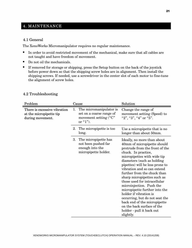
4.2 Troubleshooting
Problem Cause Solution
1. The micromanipulator is
set on a coarse range of
movement setting (“C”
or “1”).
Change the range of
movement setting (Speed) to
“2”, “3”, “4” or “5”.
2. The micropipette is too
long. Use a micropipette that is no
longer than about 50mm.
There is excessive vibration
at the micropipette tip
during movement.
3. The micropipette has
not been pushed far
enough into the
micropipette holder.
Ideally, no more than about
40mm of micropipette should
protrude from the front of the
chuck. In practice,
micropipettes with wide tip
diameters (such as holding
pipettes) will be less prone to
vibration and so can extend
further from the chuck than
sharp micropipettes such as
those used for intracellular
microinjection. Push the
micropipette further into the
holder if vibration is
occurring, but do not seat the
back end of the micropipette
on the back surface of the
holder - pull it back out
slightly.

XENOWORKS MICROMANIPULATOR SYSTEM (TOUCHDECLUTCH) OPERATION MANUAL – REV. 4.10 (20141208)
22
Problem Cause Solution
4. The O-rings in the
micropipette holder
chuck are missing or
damaged.
The micropipette holder has
been designed to minimize
vibration when used with
three O-rings in the chuck,
and when the O-rings are the
only thing contacting the
back end of the micropipette.
Less than three O-rings (or
the back of the micropipette
touching the back of the
holder) may lead to excessive
vibration. Replace all missing
or damaged O-rings.
5. The micropipette is
dragging on the bottom
or sides of the
microinjection chamber.
If the tip is touching the
bottom of the chamber, raise
the micropipette slightly by
turning the Z-axis control
counterclockwise. If the shaft
of the micropipette is
touching the side of the
chamber, consider
repositioning the
micropipette with respect to
the micromanipulator as
described in Section 4.
1. The micropipette holder
clamp has not been
tightened down
sufficiently.
Tighten the micropipette
holder clamp.
2. There is too great a
distance between the
micropipette tip and the
point where the
micropipette holder is
gripped by the holder
clamp on the
micromanipulator.
This is a different problem to
the one described in 2 and 3
above. Here there is too much
of the micropipette holder
shaft projecting from the
clamp on the
micromanipulator. Shorten
the micropipette tip-to-clamp
distance by moving the holder
outboard and clamping the
micropipette holder closer to
its tip.
There is still excessive
vibration at the
micropipette tip during
movement.
3. The fixing screws of the
mounting adapter are
not tight.
Tighten the fixing screws.

XENOWORKS MICROMANIPULATOR SYSTEM (TOUCHDECLUTCH) OPERATION MANUAL – REV. 4.10 (20141208)
23
Problem Cause Solution
4. The swing gate
thumbscrew is loose. Tighten the swing gate
thumbscrew.
5. The mechanical is not
screwed securely to the
mechanical base plate.
Ensure all four screws fixing
the mechanical to its base
plate are tight.
6. The mechanical base
plate is not locked to the
microscope adapter.
The mechanical base plate is
not locked to the microscope
adapter.
7. The micromanipulator is
at the extreme limit of
one or more of its axes.
Remove the micropipette
holder from the
micromanipulator. Activate
the “Setup” function, which
centers the motors. If
necessary, adjust the
mechanical base plate with
respect to the microscope
adapter so that the
microscope objective
intersects the center of the
micromanipulator’s Y-axis.
Realign the micropipette
holder clamp arrangement (X-
and Z-axes), so that when the
micropipette holder is
replaced in the clamp, the
micropipette tip will come as
close as possible to the
microscope’s optical axis.
Only now, should the joystick
be used to fine-position the
tip of the micropipette in the
microscope field of view.
8. The cable attached to
the mechanical is under
tension.
Release any tension by coiling
the cable once on the bench
behind, or to the side of the
microscope.
9. The center fitting of the
micropipette holder is
loose.
Tighten the fitting.
The micropipette has been
lost from the field of view.
A too-coarse range of
movement setting has been
selected, or the joystick
resistance is too loose.
Select a finer range setting
(Speed) or tighten the joystick
friction dial.

XENOWORKS MICROMANIPULATOR SYSTEM (TOUCHDECLUTCH) OPERATION MANUAL – REV. 4.10 (20141208)
24
Problem Cause Solution
One or more motors move
in the opposite direction to
that commanded by the
joystick.
One or more of the axis
polarity DIP switches are in
the wrong position.
Flip the appropriate DIP
switches (see the axis guide in
section 2.4). It is not
necessary to restart the
instrument.
1. The end of motor travel
has been reached. Set up the micropipette
alignment again.
The micropipette will not
move any lower.
2. A ‘Z-limit’ has been set. Deactivate the ‘Z-limit’ (press
the ‘Z-limit’ key once briefly.
The green LED will go out).
1. The Y-axis inversion DIP
switch is in the wrong
position.
Reverse the Y-axis DIP
switch. The micropipette appears to
move in a direction opposite
to that commanded by the
joystick, but only in the Y-
axis. 2. A micropipette with an
angled tip has been
aligned such that the
bend or “heel” of the
micropipette is touching
the dish, but the tip is
not. This is usually only
noticeable at higher
magnifications.
Angled micropipettes should
be adjusted from the start so
that they are slightly “toe-
down”, in other words, the tip
should touch the bottom of
the microinjection chamber
before the bend does.
1. No new ‘Work’ setting
was actually assigned,
and so the micropipette
moved to a different,
previously assigned
position.
Relocate the micropipette tip
and assign a new ‘Work’
position.
The micropipette does not
return to the assigned
coordinates memorized by
the ‘Work’ setting.
2. Repeated rapid, violent
movements of the
joystick may cause the
instrument to miss
information coming
from the joystick
controller to the
processing circuitry, and
so miscalculate the
correct position of
‘Work’. Normally, the
error is no more than a
few tens of microns.
Avoid violent movements of
the joystick since they not
only confuse the electronics,
they can also damage the
joystick assembly. To ensure
that the ‘Work’ position is
always current, save a new
one periodically during the
course of an experiment.

XENOWORKS MICROMANIPULATOR SYSTEM (TOUCHDECLUTCH) OPERATION MANUAL – REV. 4.10 (20141208)
25
Problem Cause Solution
3. The joystick was
inadvertently moved
during the automatic
return to the ‘Work’
position.
Press ‘Work’ again.
The movements of the
mechanical do not
correspond with the
movements of the joystick -
specifically, movements of
the Z-axis control seem to
cause “runaway”
movements of the Z-axis
motor (other anomalous
activity may also be
observed). Often, the end of
the Z-axis travel will be
reached but the motor will
not stop.
The domestic voltage supply
may have dropped below the
specification for the
instrument.
Investigate the domestic
power supply for your facility.
It may be necessary to install
a transformer to bring the
power back to normal. If you
have any questions regarding
power requirements, please
contact Sutter technical
support.
The motors “buzz”
abnormally during
movement, particularly
during movements to/from
“work” or “home” and
particularly at the ends of
axis travel.
There is some resistance
preventing the motors from
moving smoothly.
Do not touch the mechanical
during automatic movement.
Ensure that the cable
connecting the mechanical to
the controller is not under
tension – coil the cable a few
times on the bench surface
behind the microscope.
4.3 Transporting the Micromanipulator
When moving the instrument, the entire system should be disassembled and placed in its
original packaging. Shipping screws are supplied to prevent inadvertent vibrations damaging
the delicate manipulator mechanical. To install the shipping screws, follow this procedure:
1. With the instrument switched on and the mechanical still installed on the microscope
adaptor, place the joystick in the coarse (‘C’ range) setting.
2. Use the joystick to move the mechanical INWARDS, towards the center of the
microscope, exposing the outer two screws that fix the mechanical to the base plate.
3. Loosen, remove and retain these two screws.
4. Activate the ‘Setup’ function by pressing the key on the rear of the joystick.
5. Without touching the joystick further, immediately switch off the power to the
instrument.
6. Carefully unplug the connecting cable from the rear of the mechanical.
7. Remove the mechanical from the adapter plate (remove retaining screws and ensure they
are kept in a safe place).

XENOWORKS MICROMANIPULATOR SYSTEM (TOUCHDECLUTCH) OPERATION MANUAL – REV. 4.10 (20141208)
26
8. Locate the shipping screw holes. There are four through-holes in each axis slide, but only
two of the holes will line up with the correct tapped holes on the inner slide surface when
the instrument is in the ‘Setup’ position.
9. Locate the original shipping screws that should have been retained with the original
packaging, and insert them into the appropriate locations. Do not over tighten the screws
- turn them until they are lightly seated in their holes.
10. Place the mechanical in a plastic bag.
11. The mechanical is now ready for transport in the original packaging.
Take care to ensure that the shipping screws are removed before the instrument is
operated again (see Section 3 for the correct installation procedure).

XENOWORKS MICROMANIPULATOR SYSTEM (TOUCHDECLUTCH) OPERATION MANUAL – REV. 4.10 (20141208)
27
APPENDIX A. LIMITED WARRANTY
� Sutter Instrument Company, a division of Sutter Instrument Corporation, limits the
warranty on this instrument to repair and replacement of defective components for two
years from date of shipment, provided the instrument has been operated in accordance
with the instructions outlined in this manual.
� Abuse, misuse, or unauthorized repairs will void this warranty.
� Warranty work will be performed only at the factory.
� The cost of shipment both ways is paid for by Sutter Instrument during the first three
months this warranty is in effect, after which the cost is the responsibility of the
customer.
� The limited warranty is as stated above and no implied or inferred liability for direct or
consequential damages is intended.
� Consumables, PMTs, galvanometers, and Uniblitz®1 shutters are exempt from this
warranty.
� An extended warranty for up to three additional years can be purchased at the time of
ordering, or until the original warranty expires. For pricing and other information, please
contact Sutter Instrument.
1 Uniblitz® is a registered trademark of Vincent Associates.

XENOWORKS MICROMANIPULATOR SYSTEM (TOUCHDECLUTCH) OPERATION MANUAL – REV. 4.10 (20141208)
28
(This page intentionally blank.)

XENOWORKS MICROMANIPULATOR SYSTEM (TOUCHDECLUTCH) OPERATION MANUAL – REV. 4.10 (20141208)
29
APPENDIX B. ACCESSORIES
The following accessories are available for the XenoWorks Micromanipulator system.
Extensions
4-in (10.16-cm) Dovetail Extension (X285204)
Z-axis vertical extension (X285305)
Z-axis horizontal extension (X285310)
Rotating Base
Rotating base (225RBI)
Mounts
Hinged headstage mount (285HEA)
Adapters
Mounting adapter plate (X285210). For use with MT and MD series stands and platforms, or any surface with 1 inch centered holes.
Right angle adapter (X285300)
Holders
Rod holder (MP-ROD)

XENOWORKS MICROMANIPULATOR SYSTEM (TOUCHDECLUTCH) OPERATION MANUAL – REV. 4.10 (20141208)
30
(This page intentionally blank.)
XENOWORKS MICROMANIPULATOR SYSTEM (TOUCHDECLUTCH) OPERATION MANUAL – REV. 4.10 (20141208)
31
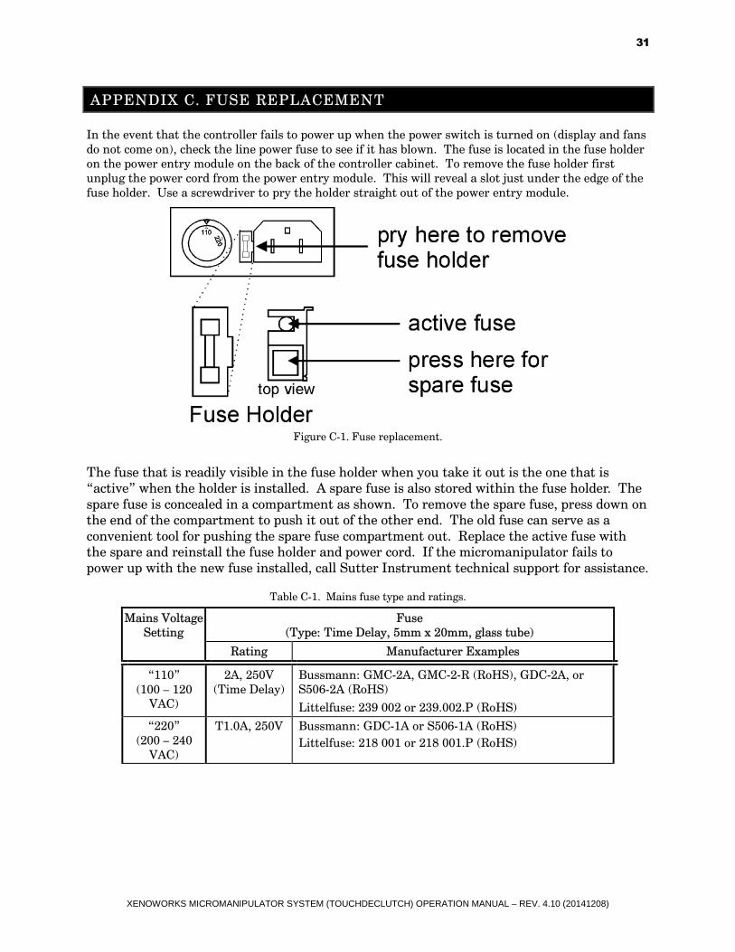
APPENDIX C. FUSE REPLACEMENT
In the event that the controller fails to power up when the power switch is turned on (display and fans
do not come on), check the line power fuse to see if it has blown. The fuse is located in the fuse holder
on the power entry module on the back of the controller cabinet. To remove the fuse holder first
unplug the power cord from the power entry module. This will reveal a slot just under the edge of the
fuse holder. Use a screwdriver to pry the holder straight out of the power entry module.
Figure C-1. Fuse replacement.
The fuse that is readily visible in the fuse holder when you take it out is the one that is
“active” when the holder is installed. A spare fuse is also stored within the fuse holder. The
spare fuse is concealed in a compartment as shown. To remove the spare fuse, press down on
the end of the compartment to push it out of the other end. The old fuse can serve as a
convenient tool for pushing the spare fuse compartment out. Replace the active fuse with
the spare and reinstall the fuse holder and power cord. If the micromanipulator fails to
power up with the new fuse installed, call Sutter Instrument technical support for assistance.
Table C-1. Mains fuse type and ratings.
Fuse
(Type: Time Delay, 5mm x 20mm, glass tube)
Mains Voltage
Setting
Rating Manufacturer Examples
“110”
(100 – 120
VAC)
2A, 250V
(Time Delay)
Bussmann: GMC-2A, GMC-2-R (RoHS), GDC-2A, or
S506-2A (RoHS)
Littelfuse: 239 002 or 239.002.P (RoHS)
“220”
(200 – 240
VAC)
T1.0A, 250V Bussmann: GDC-1A or S506-1A (RoHS)
Littelfuse: 218 001 or 218 001.P (RoHS)

XENOWORKS MICROMANIPULATOR SYSTEM (TOUCHDECLUTCH) OPERATION MANUAL – REV. 4.10 (20141208)
32
(This page intentionally blank.)

XENOWORKS MICROMANIPULATOR SYSTEM (TOUCHDECLUTCH) OPERATION MANUAL – REV. 4.10 (20141208)
33
APPENDIX D. TECHNICAL SPECIFICATIONS
Manipulator Mechanical:
3-axis stepper motor
X, Y, and Z Axes
62.5 nm per microstep
25 mm (1 in) full travel
Joystick:
Inverted joystick with integral Declutch
Height and resistance adjustable
Independent axis-polarity inversion
6-position rotary range-of-movement control
‘Setup’ function
Position memory:
One user-defined set point (‘Work’),
One user-defined axis limit (‘Z-floor’),
Two preset points (‘Home’ and ‘Setup’)
Ranges of Movement (Speed):
Table D-1. Speed settings and ranges of movement.
Range (Speed)
Setting
X & Y (1 joystick swing) Z (1 rotation)
C 12,700 µm 3,200 µm
1 3,300 µm 800 µm
2 880 µm 400 µm
3 400 µm 200 µm
4 200 µm 100 µm
5 100 µm 50 µm

XENOWORKS MICROMANIPULATOR SYSTEM (TOUCHDECLUTCH) OPERATION MANUAL – REV. 4.10 (20141208)
34
Electrical:
Input voltage (Mains): 100 – 120 VAC, 50/60 Hz,
200 – 240 VAC, 50/60 Hz
Power consumption: 200 VA max., 88 VA typical
Mains fuse (rear of cabinet):
Table D-2. Mains fuse type and ratings.
Fuse
(Type: Time Delay, 5 x 20 mm, glass tube)
Mains Voltage
Setting
Rating Manufacturer Examples
“110”
(100 – 120
VAC)
2A, 250V
(Time Delay)
Bussmann: GMC-2A, GMC-2-R (RoHS), GDC-
2A, or S506-2A (RoHS)
Littelfuse: 239 002 or 239.002.P (RoHS)
“220”
(200 – 240
VAC)
T1.0A, 250V Bussmann: GDC-1A or S506-1A (RoHS)
Littelfuse: 218 001 or 218 001.P (RoHS)
Cables (Refer to the following two tables for a description
of all possible cables.)
Table D-3. XenoWorks BRM Controller cables and receptacles/connectors.
Controller Rear Panel
Port
Connector/Receptacle
Cable Connector
Types
Connects to ... Cable Type Cable
Max.
Length
(Power entry)
3-pin male connector
◄─3-pin power standard (female)
│ 3-pin male─►
(Geographical region
dependent)
Mains power source.
10A, 250V, with
safety ground
plug
3 meters
(approx.
10 feet)
DRIVE MODULE
(25-Pin DSUB female
receptacle
◄─DB-25 male │
DB-25 female─► (straight-through)
MP-285M
(25-Pin DSUB male
connector)
Minimum of 26
awg stranded
wire with 500
Volt (see note)
3 meters
(approx.
10 feet)
JOYSTICK MODULE
(RJ45 receptacle)
RJ45 male |
RJ45 male
Joystick
CONTROL
MODULE
(RJ45 receptacle)
3 meters
(approx.
10 feet)
NOTE:: A ferrite at the controller end is strongly recommended (Fair-Rite part number 0443164-251).
Fair-Rite Products Corp., P.O. Box J, One Commercial Row, Wallkill, NY, 12589, USA

XENOWORKS MICROMANIPULATOR SYSTEM (TOUCHDECLUTCH) OPERATION MANUAL – REV. 4.10 (20141208)
35
Storage Environment:
Temperature: 0 – 70 °C (32 – 158 °F)
Humidity: 0 – 95% (non-condensing)
Operating Environment:
Temperature: 3.5 – 35 °C (38.3 – 95 °F)
Humidity: 0 – 80% (non-condensing; 80% @ 31°C (87.8°F)
decreasing linearly to 67% @ 35°C (95°F))
Regulatory: Safety - EN61010-1, CE
EMC - EN61326, CE
Cleaning: 70% alcohol (or e.g., UV)
Dimensions (H x W x D):
Mechanical: 112 x 145 x 185 mm (4.4 x 5.7 x 7.3 in)
Joystick: 265 x 240 x 226 mm (10.4 x 9.4 x 8.9 in)
Controller: 101 x 407 x 280 mm (4 x 16 x 11 in)
Weight:
Mechanical: 174 g (0.38 lb)
Joystick: 254 g (0.56 lb)
Controller: 432 g (0.95 lb)

XENOWORKS MICROMANIPULATOR SYSTEM (TOUCHDECLUTCH) OPERATION MANUAL – REV. 4.10 (20141208)
36
(This page intentionally blank.)

XENOWORKS MICROMANIPULATOR SYSTEM (TOUCHDECLUTCH) OPERATION MANUAL – REV. 4.10 (20141208)
37
INDEX
A
accessories ..............................................................29
adapters ..............................................................29
extensions...........................................................29
holders ................................................................29
mounts................................................................29
rotating base.......................................................29
Additional Features and Functions
Setup.....................................................................6
C
Centering the Micropipette with Respect to the
Joystick...............................................................13
Changing the Working Range of Movement
Setting a ‘Z-Floor’..............................................17
Changing the Working Range of Movement.......17
Cleaning the Micropipette ....................................17
controller
cable specs ..........................................................34
D
disclaimer ............................................................... iii
E
electrical
specifications ......................................................34
F
Frequently-used Functions and Features.............4
Joystick Declutch Mechanism............................4
Speed.....................................................................5
Z-floor....................................................................5
Frequently-used Functions and Features
Height Adjustment..............................................4
Frequently-used Functions and Features
Joystick Friction ..................................................4
Frequently-used Functions and Features
‘Work’ Position ....................................................5
Frequently-used Functions and Features
‘Home’ Position ...................................................5
Frequently-used Functions and Features
Micropipette Holder Clamp................................5
Frequently-used Functions and Features
Swing Gate ...........................................................5
fuse
holder ..................................................................31
location ...............................................................31
mains...................................................................34
replacement........................................................31
spare....................................................................31
fuses, replacement
mains............................................................. iii, 31
G
General Information ...............................................1
about this manual................................................1
technical support .................................................1
General Safety Information.................................. iii
glassware
precautions...........................................................v
I
Infrequently-used Functions and Features
Y-Axis On/Off.......................................................7
Infrequently-used Functions and Features ..........6
Axis Polarity.........................................................6
Installation Procedure ............................................9
Instrument Controls and Features........................2
X- and Y-axis control ...........................................3
Z-axis control........................................................4
M
mains
fuse......................................................................34
fuses .............................................................. iii, 31
voltage.................................................................34
Maintenance...........................................................21
general ................................................................21
transporting the micromanipulator.................25
troubleshooting..................................................21
Memorizing the ‘Work’ Position..........................16
mounts....................................................................29
Moving the Micropipette with the Joystick ........13
N
notes
user......................................................................39
O
Operating Instructions..........................................13
P
Packing List .............................................................1
power entry module...............................................31
Product Description ................................................1
R
resolution................................................................33

XENOWORKS MICROMANIPULATOR SYSTEM (TOUCHDECLUTCH) OPERATION MANUAL – REV. 4.10 (20141208)
38
S
safety warnings...................................................... iii
mains fuse........................................................... iii
safety warnings & precautions
operational...........................................................iv
safety warnings & precautions..............................iv
Setting the Angle of Approach of the Micropipette
Applications and Suggested Setups .................14
Microinjection chamber ....................................14
Micropipette type...............................................16
Piezo impact drive .............................................16
Working distance ...............................................16
Setting the Angle of Attack of the Micropipette.14
specifications
cleaning...............................................................35
dimensions..........................................................35
operating environment .....................................35
regulatory ...........................................................35
weight .................................................................35
specifications ..........................................................33
electrical..............................................................34
joystick................................................................33
manipulator mechanical ...................................33
ranges of movement ..........................................33
storage environment .........................................35
T
technical specifications..........................................33
technical support .....................................................1
transporting the micromanipulator.....................25
travel.......................................................................33
Troubleshooting.....................................................21
U
Using the ‘Home’ Function ..................................16
V
voltage
mains...................................................................34
W
warranty.................................................................27

XENOWORKS MICROMANIPULATOR SYSTEM (TOUCHDECLUTCH) OPERATION MANUAL – REV. 4.10 (20141208)
39
NOTES

XENOWORKS MICROMANIPULATOR SYSTEM (TOUCHDECLUTCH) OPERATION MANUAL – REV. 4.10 (20141208)
40
NOTES