xv-1439-13 isofdis 14346 static design procedure for ...people.fsv.cvut.cz/~sokol/sts3/2014...
TRANSCRIPT
International Institute of Welding – Paris Nord 2 - 90 rue des Vanesses - Villepinte BP 51362 - 95942 Roissy Ch. De Gaulle Cedex – France Phone : + 33 1 49 90 36 08/36 79/36 15/51 59 – Fax : + 33 1 49 90 36 80 – [email protected] – www.iiwelding.org
XV-1439-13 ISO/FDIS 14346: Static design procedure for welded hollow-section joints - Recommendations
08.01.2013
COMMISSION XV DESIGN, ANALYSIS AND FABRICATION OF WELDED STRUCTURES
XV-1439-13 ISO/FDIS 14346: Static design procedure for welded hollow-
section joints - Recommendations Author: ZHAO, Xiao-Ling (AUS)
Chair, Subcommission XV-E Department of Civil Engineering, Monash University Clayton, VIC 3168 Australia [email protected]
Abstract:
This International Standard gives guidelines for the design and analysis of welded uniplanar and multiplanar joints in lattice structures composed of circular (CHS), square (SHS) or rectangular (RHS) hollow sections, and of uniplanar joints in lattice structures composed of combinations of hollow sections with open sections under static loading. This International Standard is applicable to CHS or RHS Y-, X and K-joints and their multiplanar equivalents, gusset plate to CHS or RHS joints, open-section and RHS to CHS joints, and hollow-section to open-section joints.
IIW Keywords:
hollow sections, static design, lattice structures, circular hollow sections, square hollow sections, rectangular hollow sections
Notes:
IIW Commission XV review purposes only © ISO 2012 RECIPIENTS OF THIS DRAFT ARE INVITED TO SUBMIT, WITH THEIR COMMENTS, NOTIFICATION OF ANY RELEVANT PATENT RIGHTS OF WHICH THEY ARE AWARE AND TO PROVIDE SUPPORTING DOCUMENTATION.

IIW C
omm
ission
XV
revie
w pur
pose
s only
© ISO 2012
Static design procedure for welded hollow-section joints — RecommendationsProcédure statique de conception des joints soudés à section creuse — Recommandations
Reference numberISO/FDIS 14346:2012(E)
INTERNATIONAL STANDARD
ISO/FDIS14346
FINALDRAFT
RECIPIENTS OF THIS DRAFT ARE INVITED TO SUBMIT, WITH THEIR COMMENTS, NOTIFICATION OF ANY RELEVANT PATENT RIGHTS OF WHICH THEY ARE AWARE AND TO PROVIDE SUPPOR TING DOCUMENTATION.
IN ADDITION TO THEIR EVALUATION AS BEING ACCEPTABLE FOR INDUSTRIAL, TECHNOLOGICAL, COMMERCIAL AND USER PURPOSES, DRAFT INTERNATIONAL STANDARDS MAY ON OCCASION HAVE TO BE CONSIDERED IN THE LIGHT OF THEIR POTENTIAL TO BECOME STANDARDS TO WHICH REFERENCE MAY BE MADE IN NATIONAL REGULATIONS.
IIW
Voting begins on: 2012-12-04
Voting terminates on: 2013-02-04
XV-1439-13

IIW C
omm
ission
XV
revie
w pur
pose
s only
ISO/FDIS 14346:2012(E)
ii © ISO 2012 – All rights reserved
Copyright notice
This ISO document is a Draft International Standard and is copyrightprotected by ISO. Except as permitted under the applicable laws of the user’s country, neither this ISO draft nor any extract from it may be reproduced, stored in a retrieval system or transmitted in any form or by any means, electronic, photocopying, recording or otherwise, without prior written permission being secured.
Requests for permission to reproduce should be addressed to either ISO at the address below or ISO’s member body in the country of the requester.
ISO copyright officeCase postale 56 • CH-1211 Geneva 20Tel. + 41 22 749 01 11Fax + 41 22 749 09 47Email [email protected] www.iso.org
Reproduction may be subject to royalty payments or a licensing agreement.
Violators may be prosecuted.
XV-1439-13
IIW C
omm
ission
XV
revie
w pur
pose
s only
ISO/FDIS 14346:2012(E)
© ISO 2012 – All rights reserved iii
Contents Page
Foreword ..........................................................................................................................................................................................................................................v1 Scope ................................................................................................................................................................................................................................. 12 Normative references ...................................................................................................................................................................................... 13 Termsanddefinitions ..................................................................................................................................................................................... 14 Symbols and abbreviated terms ........................................................................................................................................................... 25 Requirements .......................................................................................................................................................................................................... 56 Materials ....................................................................................................................................................................................................................127 Joint types .................................................................................................................................................................................................................138 Jointclassification ............................................................................................................................................................................................199 Limit states design ...........................................................................................................................................................................................2410 Partial load and safety factors for loads and resistances ........................................................................................2511 Static design procedures ...........................................................................................................................................................................25
11.1 General ........................................................................................................................................................................................................ 2511.2 Design member forces ................................................................................................................................................................... 2511.3 Design resistance ............................................................................................................................................................................... 2511.4 Design criteria ...................................................................................................................................................................................... 25
12 Design member forces .................................................................................................................................................................................2512.1 Analysis methods ............................................................................................................................................................................... 2512.2 Design member forces ................................................................................................................................................................... 26
13 Design criteria ......................................................................................................................................................................................................2613.1 Failure modes ........................................................................................................................................................................................ 2613.2 Uniplanar joints ................................................................................................................................................................................... 2713.3 Uniplanar overlap joints with a CHS, RHS, I or Hsection chord .............................................................2813.4 Special uniplanar joints ................................................................................................................................................................ 2813.5 Multiplanar joints .............................................................................................................................................................................. 30
14 Design resistance of uniplanar CHS braces to CHS chord joints.......................................................................3014.1 Design axial resistance .................................................................................................................................................................. 3014.2 Design moment resistance......................................................................................................................................................... 31
15 Design resistance of uniplanar gusset plates, I- or H-section braces or RHS braces to CHS chord joints .............................................................................................................................................................................................................32
16 Design resistance of multiplanar joints with CHS chord .........................................................................................3317 Design resistance of uniplanar RHS braces or CHS braces to RHS chord joints ...............................34
17.1 Design axial resistance .................................................................................................................................................................. 3417.2 Design moment resistance......................................................................................................................................................... 36
18 Design resistance of uniplanar SHS or CHS braces to SHS chord joints ....................................................3718.1 Design axial resistance .................................................................................................................................................................. 3718.2 Design moment resistance......................................................................................................................................................... 38
19 Design resistance of uniplanar gusset plate to RHS joints .....................................................................................3820 Design resistance of multiplanar joints with RHS chord .........................................................................................3921 Design resistance of uniplanar CHS or RHS braces to I- or H-section chord joints ......................40
21.1 Design axial resistance .................................................................................................................................................................. 4021.2 Design moment resistance......................................................................................................................................................... 41
22 Design resistance of uniplanar overlap joints with a CHS, RHS, I- or H-section chord .............42Annex A (informative) Quality requirements for hollow sections .....................................................................................46
XV-1439-13

IIW C
omm
ission
XV
revie
w pur
pose
s only
ISO/FDIS 14346:2012(E)
iv © ISO 2012 – All rights reserved
Annex B (informative) Weld details ....................................................................................................................................................................48Annex C (informative) Partial safety factors on static strength ............................................................................................50Bibliography .............................................................................................................................................................................................................................52
XV-1439-13

IIW C
omm
ission
XV
revie
w pur
pose
s only
ISO/FDIS 14346:2012(E)
Foreword
ISO (the International Organization for Standardization) is a worldwide federation of national standards bodies (ISO member bodies). The work of preparing International Standards is normally carried out through ISO technical committees. Each member body interested in a subject for which a technical committee has been established has the right to be represented on that committee. International organizations, governmental and nongovernmental, in liaison with ISO, also take part in the work. ISO collaborates closely with the International Electrotechnical Commission (IEC) on all matters of electrotechnical standardization.
International Standards are drafted in accordance with the rules given in the ISO/IEC Directives, Part 2.
The main task of technical committees is to prepare International Standards. Draft International Standards adopted by the technical committees are circulated to the member bodies for voting. Publication as an International Standard requires approval by at least 75 % of the member bodies casting a vote.
Attention is drawn to the possibility that some of the elements of this document may be the subject of patent rights. ISO shall not be held responsible for identifying any or all such patent rights.
ISO 14346 was prepared by the International Institute of Welding, which has been approved as an international standardizing body in the field of welding by the ISO Council.
Requests for official interpretations of any aspect of this International Standard should be directed to the ISO Central Secretariat, who will forward them to the IIW Secretariat for an official response.
© ISO 2012 – All rights reserved vXV-1439-13

IIW C
omm
ission
XV
revie
w pur
pose
s only
XV-1439-13

IIW C
omm
ission
XV
revie
w pur
pose
s only
Static design procedure for welded hollow-section joints — Recommendations
1 Scope
This International Standard gives guidelines for the design and analysis of welded uniplanar and multiplanar joints in lattice structures composed of circular (CHS), square (SHS) or rectangular (RHS) hollow sections, and of uniplanar joints in lattice structures composed of combinations of hollow sections with open sections under static loading. This International Standard is applicable to CHS or RHS Y, X and Kjoints and their multiplanar equivalents, gusset plate to CHS or RHS joints, opensection and RHS to CHS joints, and hollowsection to opensection joints.
2 Normative references
The following referenced documents are indispensable for the application of this document. For dated references, only the edition cited applies. For undated references, the latest edition of the referenced document (including any amendments) applies.
ISO 630 (all parts), Structural steels
ISO 14347, Fatigue — Design procedure for welded hollow-section joints — Recommendations
ISO/TR 25901, Welding and related processes — Vocabulary
3 Termsanddefinitions
For the purposes of this document, the terms and definitions given in ISO 14347, ISO/TR 25901, and the following apply.
3.1chord face failurechordplastificationplastic failure of the chord face or plastic failure of the chord crosssection
3.2chord punching shearcrack initiation in a hollowsection chord wall leading to rupture of a brace member from the chord member
3.3chord side wall failurechord web failureyielding, crushing or instability (crippling or buckling of the chord side wall or chord web) under the relevant brace member
3.4cross-sectionclassificationidentification of the extent to which the resistance (to axial compression or bending moment) and rotation capacity of a crosssection are limited by its local buckling resistance
NOTE For example, four classes are given in Eurocode 3 (see EN 199311) together with three limits on diametertothickness ratio for CHS or widthtothickness ratio for RHS.
FINAL DRAFT INTERNATIONAL STANDARD ISO/FDIS 14346:2012(E)
© ISO 2012 – All rights reserved 1XV-1439-13

IIW C
omm
ission
XV
revie
w pur
pose
s only
ISO/FDIS 14346:2012(E)
3.5jointconfigurationtype or layout of the joint or joints in a zone within which the axes of two or more interconnected members or elements intersect
3.6local chord member yieldinglocal buckling of the chord connecting face in an overlapped joint
3.7local yielding of overlapping bracelocal yielding of overlapping platelocal yielding of bracelocal yielding of platecracking in the weld or in a brace member, or local buckling of a brace member with reduced effective width
3.8multiplanar jointin a lattice structure, a joint connecting members situated in more than one plane
3.9structural properties of a jointresistance to forces and moments in the connected members, deformation and/or rotation capacity
3.10uniplanar jointin a lattice structure, a joint connecting members situated in a single plane
4 Symbols and abbreviated terms
Ai crosssectional area of member i (i = 0, 1, 2)
As shear area of a chord member
be effective width of a plate or RHS brace member
bei effective width of an overlapping RHS brace member at the chord connection
bej effective width of an overlapped RHS brace member at the chord connection
be,ov effective width of an overlapping RHS brace member at the overlapped brace connection
be,p effective width for punching shear
bi overall outofplane width of a plate or RHS or I or Hmember i (i = 0, 1, 2)
bw effective width for the web of an I or Hsection, or RHS side wall
C1 coefficient used in the chord stress function Qf as shown in Tables 2, 4, 6, and 9
c coefficient defined in Table 13
cs coefficient for effective shear area
de effective width of a CHS brace member
dei effective width of an overlapping CHS brace member at the chord connection
dej effective width of an overlapped CHS brace member at the chord connection
2 © ISO 2012 – All rights reservedXV-1439-13

IIW C
omm
ission
XV
revie
w pur
pose
s only
ISO/FDIS 14346:2012(E)
de,ov effective width of an overlapping CHS brace member at the overlapped brace connection
di overall diameter of CHS member i (i = 0, 1, 2)
dw depth of the web of an I or Hsection chord member (dw h0 −2t0 −2r)
e noding eccentricity of a joint, shown in Figure 1 h), with a positive value of e representing an offset from the chord centreline towards the outside of the truss
Fax axial force in a brace member
Fgap,0* design resistance for the axial force in a chord member at the gap location
Fgap,0 design value of the axial force in a chord member at the gap location
Fi* design resistance of the joint, expressed in terms of the axial force in member i (i = 1, 2)
Fi design value of the axial force in member i (i = 0, 1, 2)
Fpl,0 axial yield capacity of a chord member
Fs* design resistance for the shear force of the brace to chord connection in an overlapped joint
Fs,gap,0 design value of the shear force in a chord member at the gap location
Fs,pl,0 shear yield capacity of a chord member
Fs,0 design value of the shear force in a chord member
g gap between the brace members in a K- or N-joint, defined in Figure 1 h)
gt transverse gap in KK-joints, defined in Figure 1 n)
hi overall inplane depth of a plate or RHS or I or Hsection member i (i = 0, 1, 2)
hz distance between the centres of gravity of the effective parts of the brace (beam) as shown in Table 12
i integer subscript used to designate a member of a joint: 0 denotes a chord member; 1, 2 denote the brace members.In joints with two brace members, 1 normally denotes the compression brace and 2 the tension brace. For a single brace, i = 1 whether it is subject to compression or tension. For an overlap type joint, i is the integer subscript to designate the overlapping brace
j integer subscript used to designate the overlapped brace member in overlap type joints
kb factor defined in Table 3
ℓb,eff. effective perimeter for local yielding of the (overlapping) brace
ℓp,eff. effective perimeter for chord punching shear
Mi design value of the moment in member i (i = 0, 1, 2)
M iip,* design resistance of the joint, expressed in terms of the inplane moment in member i (i = 1, 2)
© ISO 2012 – All rights reserved 3XV-1439-13

IIW C
omm
ission
XV
revie
w pur
pose
s only
ISO/FDIS 14346:2012(E)
Mip,i design value of the inplane moment in member i (i = 1, 2)
M iop,* design resistance of the joint, expressed in terms of the outofplane moment in member i (i = 1,
2)
Mop,i design value of the outofplane moment in member i (i = 1, 2)
Mpl,0 plastic moment capacity of a chord member
N factor to account for chord stress in Qf function (see applicable table)
Ov overlap ratio, expressed as a percentage O qpv = ×100 %
Ov, limitoverlap limit for brace shear check
P length of the projected contact area of the overlapping brace member onto the face of the chord, in the absence of the overlapped brace member, in a K- or N-joint, defined in Figure 1 i)
Qf chord stress function as defined in Tables 2, 4, 6, and 9
Qu function in the design resistance equation as defined in Tables 2, 3, 4, 6, 7, and 8
Qub function in the design resistance equation for brace bending as defined in Table 4
Q length of overlap, measured at the face of the chord, between one brace member toe and the position of the other projected brace member toe, in a K- or N-joint, defined in Figure 1 i)
R fillet radius of an I- or H-section
ro external corner radius of an RHS
T wall thickness
ti wall thickness (for CHS or RHS) or flange thickness (for I- or H-section) of member i (i = 0, 1, 2)
tw web thickness of an I or Hsection
Wel,i elastic section modulus of member i (i = 0, 1, 2)
Wpl,i plastic section modulus of member i (i = 0, 1, 2)
α factor used in the expression of As in Tables 6 and 11
β ratio of the mean diameter or width of the brace members, to that of the chord
for T, Y and Xjoints β =dd
db
bb
1
0
1
0
1
0
or or
for K and Njoints β =+ + + + +d dd
b bb
b b h hb
1 2
0
1 2
0
1 2 1 2
02 2 4or or
for plate to CHS β =bd
1
0
4 © ISO 2012 – All rights reservedXV-1439-13

IIW C
omm
ission
XV
revie
w pur
pose
s only
ISO/FDIS 14346:2012(E)
for plate to RHS β =bb
1
0
γ ratio of the chord width or diameter to twice the chord thickness γ =dt
bt
0
0
0
02 2or
γF partial load factor on applied loading
γM partial safety factor on joint resistance
η ratio of the brace member depth to the chord diameter or width η =hd
hb
1
0
1
0
or
θi included angle between brace member i and the chord (i = 1, 2)
λ slenderness
µ multiplanar factor defined in Tables 5 and 10
σk design stress for chord side wall failure
σu ultimate tensile stress
σy yield stress
σyi yield stress of member i (i = 0, 1, 2)
ϕ angle between the planes in a multiplanar joint defined in Figures 1 j) to o), or resistance factor
χ reduction factor for (column) buckling
CHS circular hollow section
RHS rectangular hollow section
SHS square hollow section
5 Requirements
The following conditions are requirements for hollowsection joints.
— Steel grades shall be according to Clause 6.
— Hollowsection joint types shall be according to Clause 7.
— The nominal wall thickness of hollow sections shall be limited to a minimum of 2,5 mm.
— For hollowsection chords with a wall thickness greater than 25 mm, the steel shall meet adequate through thickness properties as specified in ISO 630.
— The ends of members that meet at a joint shall be prepared in such a way that their crosssectional shape is not modified. Flattened end joints and cropped end joints are not covered in this International Standard.
— Where brace members are welded to a chord member, the included angle between brace and chord (θi) should be at least 30°. This is to ensure that proper welds can be made. For angles less than 30°, confirmation that sound welds can be made should be obtained from the fabricator.
© ISO 2012 – All rights reserved 5XV-1439-13

IIW C
omm
ission
XV
revie
w pur
pose
s only
ISO/FDIS 14346:2012(E)
— In gaptype joints, to ensure that there is adequate clearance to form satisfactory welds, the gap between adjacent brace members shall not be less than the sum of the brace member thicknesses (t1 + t2).
— In overlaptype joints, the overlap shall be large enough to ensure that the interconnection of the brace members is sufficient for adequate shear transfer from one brace to the other. In any case, the overlap ratio (defined in Clause 4) shall be at least 25 %.
— Where overlapping brace members are of different widths, the narrower member shall overlap the wider.
— Where overlapping brace members with the same width have different thicknesses and/or different strength grades, the member with the lowest tiσyivalue shall overlap the other member.
— In gap and overlap Kjoints, the noding eccentricity, e, shown in Figure 1 h) and i), produces a primary bending moment which requires consideration when designing truss members.
— In gap and overlap Kjoints, restrictions are placed on the noding eccentricity, e, shown in Figure 1 h) and i). Within the specified limits (e ≤ 0,25d0 or e ≤ 0,25h0), the bending moment due to this eccentricity is taken into account, for its effect on joint resistance, in the Qf term (a function to account for chord stress at the connection face). If the noding eccentricty, e, exceeds the limits in the previous sentence, the effect of the resulting bending moment on the joint resistance shall be taken into account by distributing part of the total eccentricity moment to the brace members. (In such cases, the joint resistance shall then be determined by checking the interaction of brace axial load and brace bending moment.)
— For joints with one (or both) chord end(s) not connected to other members, the chord shall be extended from the centre of the joint over a length of 3,5d0 or 3,5b0 or the end(s) shall be welded to a cap plate with a thickness of at least 1,5t0 or 10 mm.
a) T-joint
6 © ISO 2012 – All rights reservedXV-1439-13
IIW C
omm
ission
XV
revie
w pur
pose
s only
ISO/FDIS 14346:2012(E)
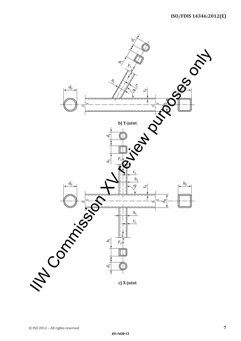
b) Y-joint
c) X-joint
© ISO 2012 – All rights reserved 7XV-1439-13
IIW C
omm
ission
XV
revie
w pur
pose
s only
ISO/FDIS 14346:2012(E)
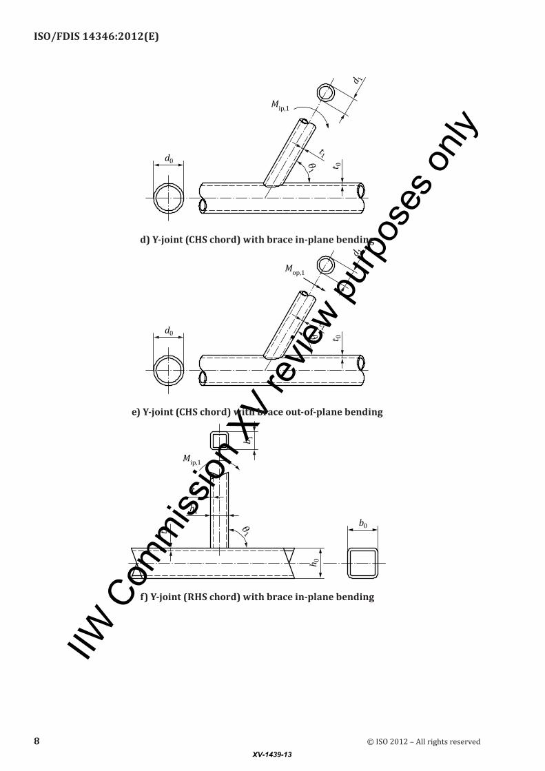
d) Y-joint (CHS chord) with brace in-plane bending
e) Y-joint (CHS chord) with brace out-of-plane bending
f) Y-joint (RHS chord) with brace in-plane bending
8 © ISO 2012 – All rights reservedXV-1439-13
IIW C
omm
ission
XV
revie
w pur
pose
s only
ISO/FDIS 14346:2012(E)
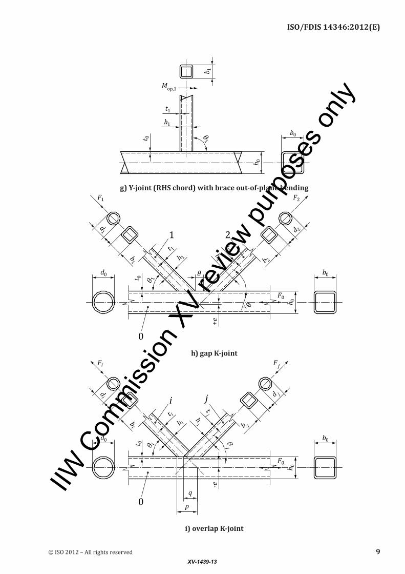
g) Y-joint (RHS chord) with brace out-of-plane bending
h) gap K-joint
i) overlap K-joint
© ISO 2012 – All rights reserved 9XV-1439-13
IIW C
omm
ission
XV
revie
w pur
pose
s only
ISO/FDIS 14346:2012(E)
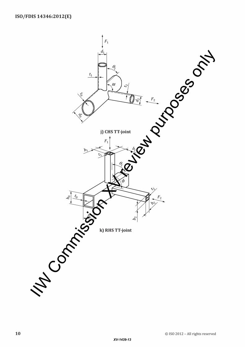
j) CHS TT-joint
k) RHS TT-joint
10 © ISO 2012 – All rights reservedXV-1439-13

IIW C
omm
ission
XV
revie
w pur
pose
s only
ISO/FDIS 14346:2012(E)
l) CHS XX-joint
m) RHS XX-joint
© ISO 2012 – All rights reserved 11XV-1439-13
IIW C
omm
ission
XV
revie
w pur
pose
s only
ISO/FDIS 14346:2012(E)
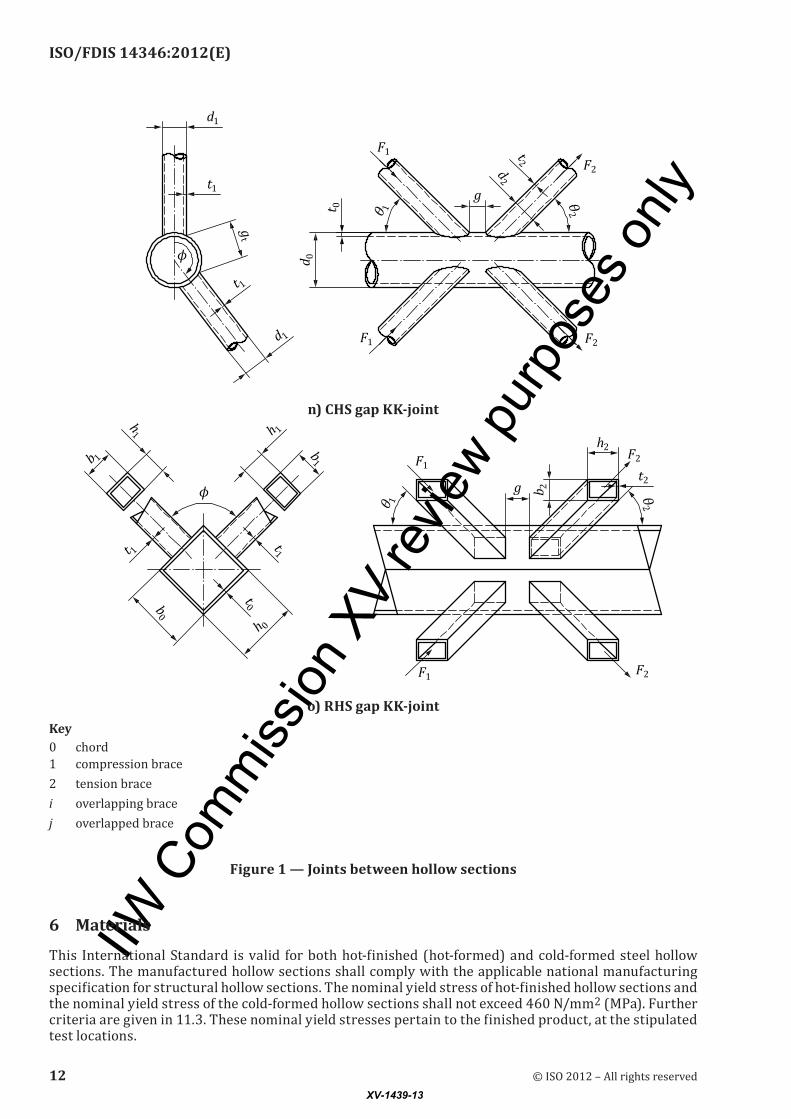
n) CHS gap KK-joint
o) RHS gap KK-jointKey0 chord1 compression brace2 tension bracei overlapping bracej overlapped brace
Figure 1 — Joints between hollow sections
6 Materials
This International Standard is valid for both hot-finished (hot-formed) and cold-formed steel hollow sections. The manufactured hollow sections shall comply with the applicable national manufacturing specification for structural hollow sections. The nominal yield stress of hot-finished hollow sections and the nominal yield stress of the coldformed hollow sections shall not exceed 460 N/mm2 (MPa). Further criteria are given in 11.3. These nominal yield stresses pertain to the finished product, at the stipulated test locations.
12 © ISO 2012 – All rights reservedXV-1439-13
IIW C
omm
ission
XV
revie
w pur
pose
s only
ISO/FDIS 14346:2012(E)
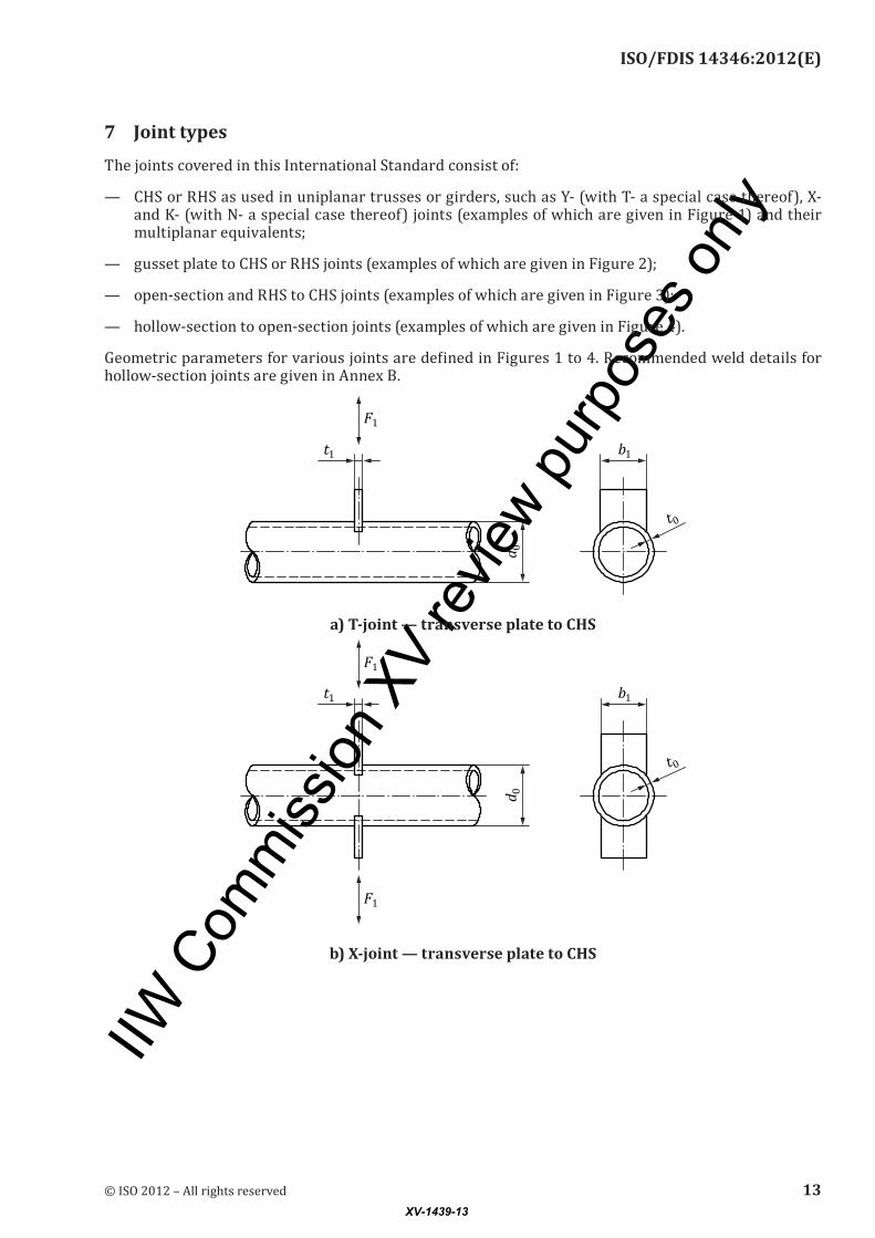
7 Joint types
The joints covered in this International Standard consist of:
— CHS or RHS as used in uniplanar trusses or girders, such as Y (with T a special case thereof), X and K (with N a special case thereof) joints (examples of which are given in Figure 1) and their multiplanar equivalents;
— gusset plate to CHS or RHS joints (examples of which are given in Figure 2);
— opensection and RHS to CHS joints (examples of which are given in Figure 3);
— hollowsection to opensection joints (examples of which are given in Figure 4).
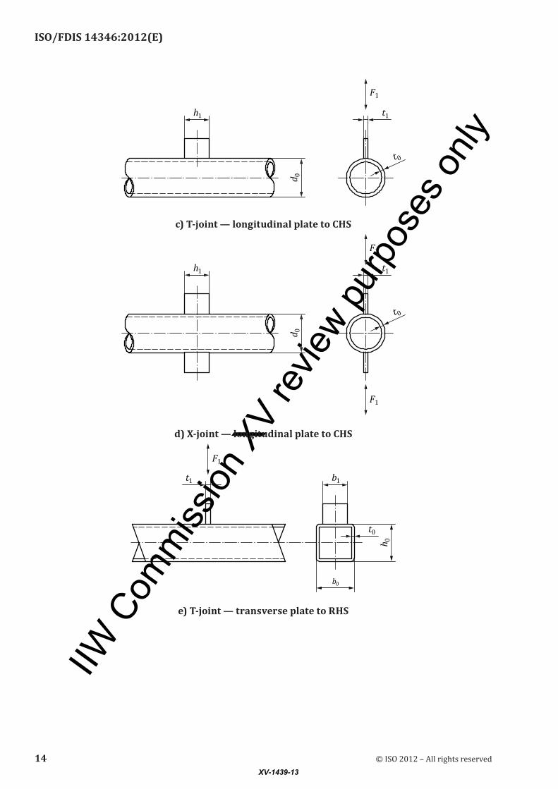
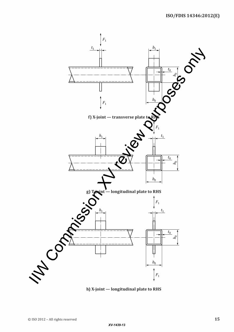
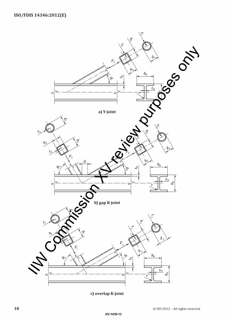
Geometric parameters for various joints are defined in Figures 1 to 4. Recommended weld details for hollowsection joints are given in Annex B.
a) T-joint — transverse plate to CHS
b) X-joint — transverse plate to CHS
© ISO 2012 – All rights reserved 13XV-1439-13
IIW C
omm
ission
XV
revie
w pur
pose
s only
ISO/FDIS 14346:2012(E)
c) T-joint — longitudinal plate to CHS
d) X-joint — longitudinal plate to CHS
e) T-joint — transverse plate to RHS
14 © ISO 2012 – All rights reservedXV-1439-13
IIW C
omm
ission
XV
revie
w pur
pose
s only
ISO/FDIS 14346:2012(E)
f) X-joint — transverse plate to RHS
g) T-joint — longitudinal plate to RHS
h) X-joint — longitudinal plate to RHS
© ISO 2012 – All rights reserved 15XV-1439-13

IIW C
omm
ission
XV
revie
w pur
pose
s only
ISO/FDIS 14346:2012(E)
i) T-joint — longitudinal through plate to RHS
Figure 2 — Joints between gusset plates and CHS or RHS chords
a) T-joint
b) X-joint
16 © ISO 2012 – All rights reservedXV-1439-13

IIW C
omm
ission
XV
revie
w pur
pose
s only
ISO/FDIS 14346:2012(E)
c) T-joint
d) X-joint
Figure 3 — Joints between open section or RHS braces and CHS chords
© ISO 2012 – All rights reserved 17XV-1439-13
IIW C
omm
ission
XV
revie
w pur
pose
s only
ISO/FDIS 14346:2012(E)
a) Y-joint
b) gap K-joint
c) overlap K-joint
18 © ISO 2012 – All rights reservedXV-1439-13

IIW C
omm
ission
XV
revie
w pur
pose
s only
ISO/FDIS 14346:2012(E)
d) T-joint subject to in-plane bendingKey0 I or Hsection chord1 RHS brace (beam)
Figure 4 — Joints between CHS or RHS braces and open-section chords
8 Jointclassification
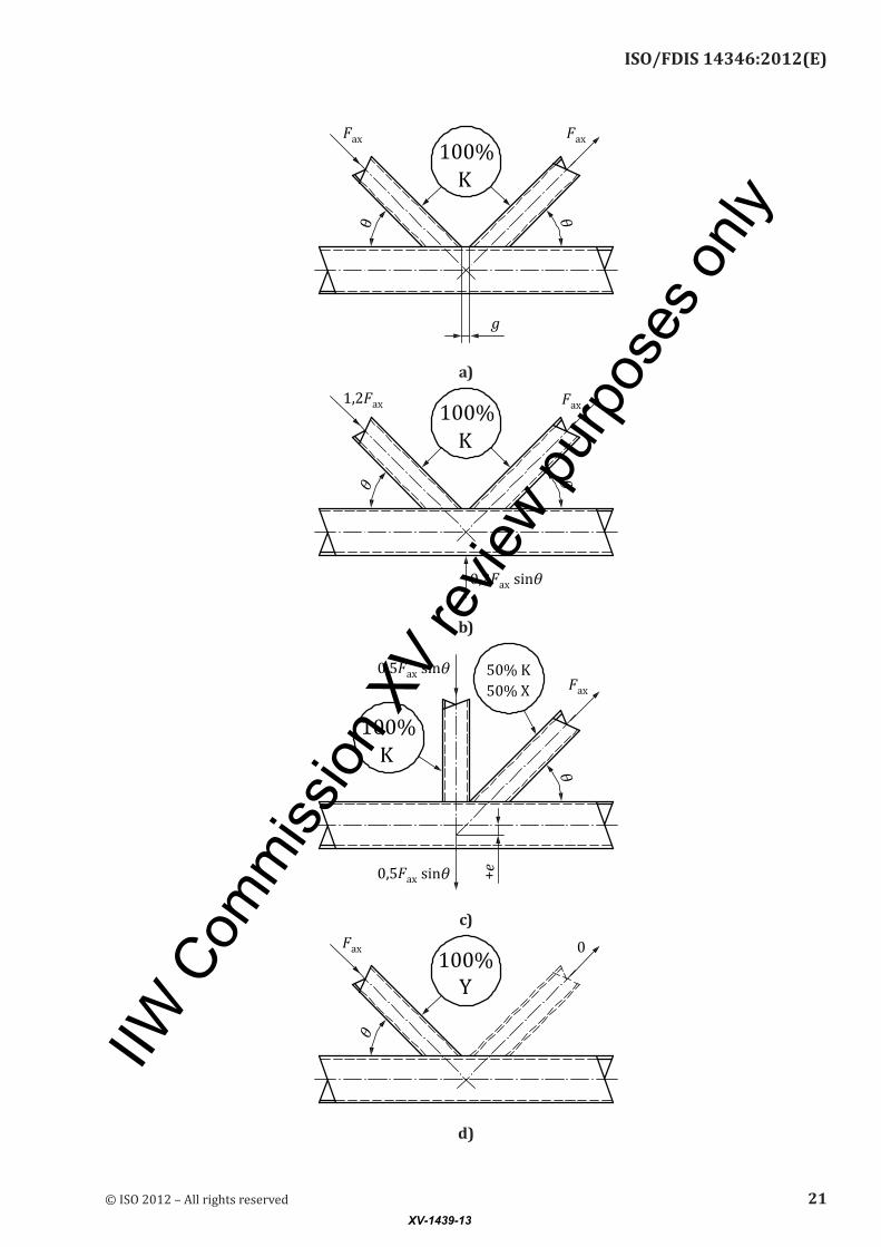
Hollowsection planar truss joints consist of one or more brace members that are directly welded to a continuous chord that passes through the joint. The classification of hollow-section truss-type joints as K (which includes N), Y (which includes T) or Xjoints is based on the method of force transfer in the joint, not on the physical appearance of the joint. The joint types can be defined as follows.
a) When the force component normal to the chord in a brace member (Faxsinθ) is equilibrated by beam shear in the chord member, the joint is classified as a T-joint when the brace is perpendicular to the chord, otherwise it is classified as a Y-joint.
b) When the force component normal to the chord in a brace member (Faxsinθ) is essentially equilibrated (within 20 %) by loads in other brace member(s) on the same side of the joint, the joint is classified as a Kjoint. The relevant gap is, in principle, between the primary brace members whose loads equilibrate. An Njoint is to be considered as a type of Kjoint with one brace at 90°.
c) When the force component normal to the chord (Faxsinθ) is transmitted through the chord member and is equilibrated by brace member(s) on the opposite side, the joint is classified as an X-joint.
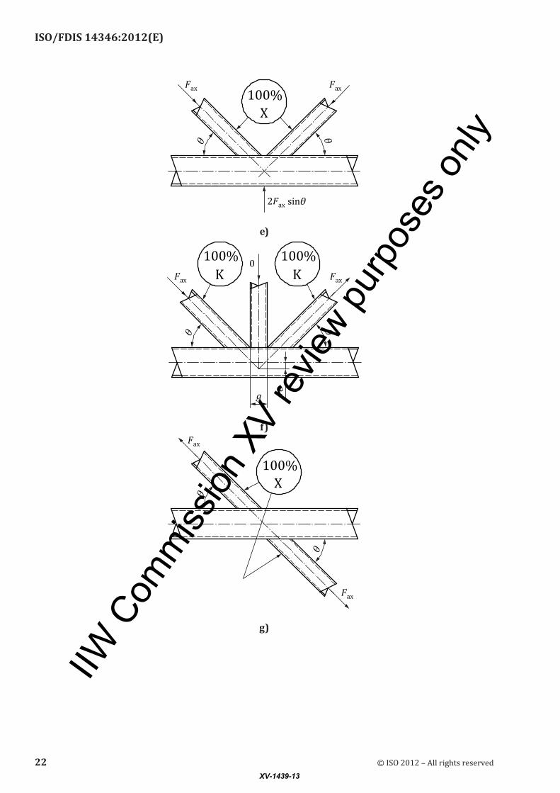
Examples of such classification are shown in Figure 5.
When brace members transmit part of their load as Kjoints and part of their load as T, Y, or Xjoints, the adequacy of each brace needs to be determined by linear interaction of the proportion of the brace load involved in each type of load transfer. One Kjoint, in Figure 5 b), illustrates that the brace force components normal to the chord member may differ by as much as 20 % and still be deemed to exhibit Kjoint behaviour. This is to accommodate slight variations in brace member forces along a typical truss, caused by a series of panel point loads. The Njoint in Figure 5 c), however, has a ratio of brace force components normal to the chord member of 2:1. That particular joint needs to be analysed as both a “pure” Kjoint (with balanced brace forces) and an Xjoint (because the remainder of the diagonal brace
© ISO 2012 – All rights reserved 19XV-1439-13

IIW C
omm
ission
XV
revie
w pur
pose
s only
ISO/FDIS 14346:2012(E)
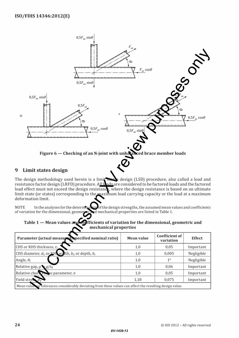
load is being transferred through the joint), as shown in Figure 6. For the diagonal tension brace in that particular joint, one would need to check that:
0 5 0 51 0
, ,,
* *
FF
FF
ax
K
ax
X
+ ≤
where
FK* is the resistance of a Kjoint;
FX* is the resistance of an Xjoint.
20 © ISO 2012 – All rights reservedXV-1439-13
IIW C
omm
ission
XV
revie
w pur
pose
s only
ISO/FDIS 14346:2012(E)
a)
b)
c)
d)
© ISO 2012 – All rights reserved 21XV-1439-13
IIW C
omm
ission
XV
revie
w pur
pose
s only
ISO/FDIS 14346:2012(E)
e)
f)
g)
22 © ISO 2012 – All rights reservedXV-1439-13

IIW C
omm
ission
XV
revie
w pur
pose
s only
ISO/FDIS 14346:2012(E)
h)
i)
Figure5—Examplesofhollow-sectionjointclassification
© ISO 2012 – All rights reserved 23XV-1439-13
IIW C
omm
ission
XV
revie
w pur
pose
s only
ISO/FDIS 14346:2012(E)
Figure 6 — Checking of an N-joint with unbalanced brace member loads
9 Limit states design
The design methodology used herein is a limit states design (LSD) procedure, also called a load and resistance factor design (LRFD) procedure. All loads are considered to be factored loads and the factored load effect must not exceed the design resistance, where the design resistance is based on an ultimate limit state (or states) corresponding to the maximum load carrying capacity or the load at a maximum deformation limit.
NOTE In the analyses for the determination of the design strengths, the assumed mean values and coefficients of variation for the dimensional, geometric and mechanical properties are listed in Table 1.
Table1—Meanvaluesandcoefficientsofvariationforthedimensional,geometricandmechanical properties
Parameter(actualmeasured/specifiednominalratio) Mean value Coefficientofvariation Effect
CHS or RHS thickness, ti 1,0 0,05 ImportantCHS diameter, di, or RHS width, bi, or depth, hi 1,0 0,005 NegligibleAngle, θi 1,0 1° NegligibleRelative gap, g’ = g/t0 1,0 0,06 ImportantRelative chord stress parameter, n 1,0 0,05 ImportantYield stress, σy 1,18 0,075 Important Mean values or tolerances considerably deviating from these values can affect the resulting design value.
24 © ISO 2012 – All rights reservedXV-1439-13

IIW C
omm
ission
XV
revie
w pur
pose
s only
ISO/FDIS 14346:2012(E)
10 Partial load and safety factors for loads and resistances
10.1 The partial load factors for applied loading, for the ultimate (γF) limit state, shall be taken from the relevant building code or specification being used.
10.2 Partial safety factors (γM) or resistance factors (ϕ) for hollowsection joints have already been incorporated into the design resistance formulae given in Clauses 14 to 22. For informational purposes, the partial safety factors used in the various joint resistance formulae are given in Table C.1.
11 Static design procedures
11.1 General
The static design procedures can be summarized as the following three steps:
a) Step one: determine the design member forces in the brace(s) and chord;
b) Step two: determine the design resistance of the joint;
c) Step three: apply design criteria to assess if the joint resistance is sufficient.
11.2 Design member forces
The design member forces shall be determined using Clause 12.
11.3 Design resistance
The design resistance for various types of joints is given in Clauses 14 to 22, where the partial safety factors listed in Table C.1 have already been incorporated. For material with a nominal yield stress (σy) exceeding 355 N/mm2, the joint resistances specified in this International Standard shall be multiplied by 0,9. In addition, if the nominal yield stress exceeds 0,8 of the nominal ultimate stress (σu) then the design yield stress shall be taken as 0,8σu.
11.4 Design criteria
The design member forces determined in 11.2 shall not exceed the design resistance given in 11.3 as appropriate. The design criteria are given in Clause 13.
12 Design member forces
12.1 Analysis methods
12.1.1 For welded hollowsection structures, design member forces require determination by analysis of the complete structure, in which nodal eccentricity of the member centrelines at the joint is taken into account.
12.1.2 Simplified analysis methods are acceptable for triangulated trusses or lattice girders with eccentricities e ≤ 0,25d0 or e ≤ 0,25h0 for gap and overlap Kjoints; these are as follows.
a) Pinjointed analysis. Moments due to eccentricity need to be taken into account for the design of chords.
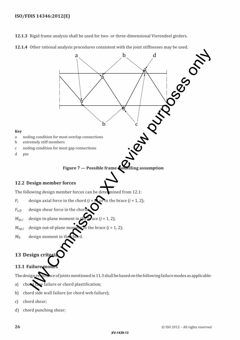
b) Continuous chords with pinended braces. Axial forces and bending moments in the members can be determined using a structural analysis assuming a continuous chord and pinended braces (see Figure 7). This produces axial forces in the braces, and both axial forces and bending moments in the chord. This modelling assumption is particularly appropriate for loads on the chord members which are away from the node points or panel points.
© ISO 2012 – All rights reserved 25XV-1439-13
IIW C
omm
ission
XV
revie
w pur
pose
s only
ISO/FDIS 14346:2012(E)
12.1.3 Rigid frame analysis shall be used for two or threedimensional Vierendeel girders.
12.1.4 Other rational analysis procedures consistent with the joint stiffnesses may be used.
Keya noding condition for most overlap connectionsb extremely stiff membersc noding condition for most gap connectionsd pin
Figure 7 — Possible frame modelling assumption
12.2 Design member forces
The following design member forces can be determined from 12.1:
Fi design axial force in the chord (i = 0) or in the brace (i = 1, 2);
Fs,0 design shear force in the chord;
Mip,i design inplane moment in the brace (i = 1, 2);
Mop,i design outofplane moment in the brace (i = 1, 2);
M0 design moment in the chord.
13 Design criteria
13.1 Failure modes
The design resistance of joints mentioned in 11.3 shall be based on the following failure modes as applicable:
a) chord face failure or chord plastification;
b) chord side wall failure (or chord web failure);
c) chord shear;
d) chord punching shear;
26 © ISO 2012 – All rights reservedXV-1439-13

IIW C
omm
ission
XV
revie
w pur
pose
s only
ISO/FDIS 14346:2012(E)
e) local yielding of (overlapping) brace (or plate);
f) local chord member yielding;
g) brace shear.
NOTE These failure mode descriptions are used in Tables 2 to 15, which list design resistances.
Weld failure shall be avoided.
13.2 Uniplanar joints
13.2.1 General
For joint types described in Clauses 14, 15, 17, 18, 19, 21 and 22, the following design criteria apply.
a) For joints within the range of validity given in Tables 2 to 15, only failure modes listed in the resistance tables need to be considered. The design resistance of a joint shall be taken as the minimum value for these criteria.
b) For joints outside the range of validity mentioned in a), all criteria given in 13.1 shall be considered.
In joints with the brace member(s) subject only to axial forces, the design axial force Fi shall not exceed the design axial resistance of the welded joint Fi
* , expressed as an axial force in the brace member.
13.2.2 Uniplanar joints with CHS chord
The following design criteria apply:
a) for overlap joints, see 13.3;
b) for special uniplanar joints with braces on both sides of the chord, see 13.4;
c) In joints with the brace member(s) subjected to combined bending and axial forces, apply the following:
FF
M
M
M
Mi
i
i
i
i
i*
ip,
ip,
op,
op,
+
+ ≤* *
,
2
1 0
where
Fi, Mip,i, and Mop,i are member forces determined in Clause 12;
Fi* , M iip,
* and M iop,* are design resistances determined in Clauses 14 and 15.
13.2.3 Uniplanar joints with RHS chord
The following design criteria apply:
a) for overlap joints, see13.3;
b) for special uniplanar joints with braces on both sides of the chord, see 13.4;
c) for welded T, Y, X, and gap Kjoints between SHS or CHS brace members and SHS chord members only, where the geometry of the joints is within the range of validity given in Table 6 and also satisfies the additional conditions given in Table 8, the only consideration is chord plastification;
d) in joints with the brace member(s) subjected to a combination of bending and axial forces, the following design criterion applies:
© ISO 2012 – All rights reserved 27XV-1439-13
IIW C
omm
ission
XV
revie
w pur
pose
s only
ISO/FDIS 14346:2012(E)
FF
M
M
M
Mi
i
i
i
i
i* * *
,+ + ≤ip,
ip,
op,
op,
1 0
where
Fi, Mip,i, and Mop,i are member forces determined in Clause 12;
Fi* , M iip,
* and M iop,* are design resistances determined in Clauses 17 and 18.
13.2.4 Uniplanar joints with CHS or RHS brace to I- or H-section chord
The following design criteria apply:
a) for overlap joints, see 13.3;
b) in joints with the brace member(s) subjected to a combination of inplane bending and axial forces, the following applies:
FF
M
Mi
i
i
i* *
,+ ≤ip,
ip,
1 0
where
Fi and Mip,i are member forces determined in Clause 12;
Fi* and M iip,
* are design resistances determined in Clause 21.
13.3 Uniplanar overlap joints with a CHS, RHS, I- or H-section chord
Requirements are:
a) the design axial forces in overlap joints shall not exceed the design axial resistances given in Tables 13 and 14;
b) the local yielding of the overlapping brace criterion and the local chord yielding criterion in Table 13 always apply;
c) the brace shear criterion in Table 14 should only be checked if Ov > Ov,limit:
Ov,limit = 60 % if the hidden seam of the overlapped brace is not welded,
Ov,limit = 80 % if the hidden seam of the overlapped brace is welded.
For overlap joints with hi < bi and/or hj < bj, the brace shear criterion shall always be checked.
13.4 Special uniplanar joints
The design resistance of several types of special uniplanar joints shown in Figure 8 a) to d), which are not dealt with in 13.2 and 13.3, can be directly related to that of the basic types (i.e. X and K).
28 © ISO 2012 – All rights reservedXV-1439-13

IIW C
omm
ission
XV
revie
w pur
pose
s only
ISO/FDIS 14346:2012(E)
a) b)
c) d)
Figure 8 — Special types of uniplanar joints
The following criteria apply:
in the joint in Figure 8 a), F F *1 1≤ , in which F1* is the design resistance of an Xjoint given in
Table 2 or Table 6;
in the joint in Figure 8 b), F F F * i1 isin sin sinθ θ θ1 2 2+ ≤ , in which Fi* is the design resistance of an
Xjoint given in Table 2 or Table 6, where Fi*
isinθ is the larger of F *1 1sinθ and F *2 2sinθ ;
© ISO 2012 – All rights reserved 29XV-1439-13

IIW C
omm
ission
XV
revie
w pur
pose
s only
ISO/FDIS 14346:2012(E)
in the joint in Figure 8 c), F F *1 1≤ and F F *2 2≤ , in which F1* and F2
* are the design resistances of a Kjoint, given in Table 2 or Table 6 — the force in the chord is the total chord force;
in the joint in Figure 8 d), F F *1 1≤ and F F *2 2≤ , in which F1* and F2
* are the design resistances of a Kjoint, given in Table 2 or Table 6.
Further, the following chord shear criteria apply at section 11 in Figure 8 d).
For CHS gap joints:
FF
FF
gap,0
pl,0
s,gap,0
s,pl,0
+
≤
2 2
1 0,
in which Fgap,0 is the design value of the axial force in the chord, Fs,gap,0 is the design value of the shear force in the chord, both at the gap location. Fpl,0 is the axial yield capacity of the chord, i.e. F Apl,0 y0= 0σ ,
and Fs,pl,0 is the shear yield capacity of the chord, i.e. FA
s,pl,0 y0= 0 582 0, σ
πFor gap joints with an RHS chord or an I or Hsection chord:
F F A F F A A As,gap,0 s,pl,0 y s gap,0 gap,0 s y0 sand≤ = ≤ = − +0 58 0 0, ( )*σ σ σ yy0s,gap,0
s,pl,0
1
2
−
FF
in which As is given in Table 6 for RHS chord joints, and Table 11 for I or Hsection chord joints.
13.5 Multiplanar joints
13.5.1 Multiplanar joints with CHS chord
For multiplanar joints with CHS chord, as described in Clause 16, the following design criteria apply.
In each relevant plane of a multiplanar joint, the design criteria given in 13.2.1 and 13.2.2 shall be satisfied using the design resistance with the multiplanar factors given in Table 5.
13.5.2 Multiplanar joints with RHS chord
For multiplanar joints with RHS chord, as described in Clause 20, the following design criteria apply.
In each relevant plane of a multiplanar joint, the design criteria given in 13.2.1 and 13.2.3 shall be satisfied using the design resistance with the multiplanar factors given in Table 10.
14 Design resistance of uniplanar CHS braces to CHS chord joints
14.1 Design axial resistance
The design axial resistance of uniplanar CHS to CHS joints shall be determined using Table 2.
30 © ISO 2012 – All rights reservedXV-1439-13

IIW C
omm
ission
XV
revie
w pur
pose
s only
ISO/FDIS 14346:2012(E)
Table 2 — Design axial resistance of uniplanar CHS braces to CHS chord joints
Limit state Axially loaded joints with CHS braces and chord
Chordplastification F Q Qt
ii
*
sin= u f
y0σθ
02
Chord punching shear (for d d ti ≤ −0 02 ) F d ti i
i
i
* ,sin
sin=
+0 58
1
20 2
σθθ
y0
π
Function Qu
T- and Y-joints See Figure 1 a) and b) Qu = +( )2 6 1 6 8 2 0 2, , ,β γ
X-jointsa See Figure 1 c) Qu = +
−
2 6
1
1 0 7
0 15,,
,ββ
γ
Gap K-joints See Figure 1 h) Q
g tu = +( ) +
+
1 65 1 8 11
1 2
1 6 0 3
00 8
,, ( / )
, ,
,β γ
Function Qf
Q n C
f = −( )1 1 nFF
MM
= +0 0
pl,0 pl,0
in connecting face
Chord compression stress (n < 0) Chord tension stress (n ≥ 0)T-, Y- and X-joints C1 = 0,45 − 0,25β
C1 = 0,20Gap K-joints C1 = 0,25
Range of validity
General
0 2 1 0, ,≤ ≤d di / 0 e d/ 0 ≤ 0 25, g t t≥ +1 2
θ i ≥ °30 σ σy y0i ≤ andσ σy u≤ 0 8,
CHS chordCompression class 1 or 2b andd t0 0/ ≤ 50 (for Xjoints: d t0 0/ ≤ 40 )
Tension d t0 0/ ≤ 50 (for Xjoints: d t0 0/ ≤ 40 )
CHS bracesCompression class 1 or 2 andd ti i/ ≤ 50
Tension d ti i/ ≤ 50
a For Xjoints with cosθ β1 > , the chord should also be checked for shear failure.b Examples of cross-section classification can be found in Eurocode 3 (see EN 1993-1-1:2005,[4] 5.5).
14.2 Design moment resistance
The design moment resistance of uniplanar CHS to CHS joints shall be determined using Table 3.
© ISO 2012 – All rights reserved 31XV-1439-13

IIW C
omm
ission
XV
revie
w pur
pose
s only
ISO/FDIS 14346:2012(E)
Table 3 — Design moment resistance of uniplanar CHS braces to CHS chord joints
Limit state Joints with CHS braces and chord
Chordplastification M Q Qtd1
02
11
*
sin= u f
y0σθ
Chord punching shear(for d d t1 0 02≤ − )
M d tk
1 12
01
0 58* ,sin
= σθy0b
Brace in-plane bending
kb =+1 3
4
1
1
sin
sin
θθ
Brace out-of-plane bending
kb =+3
4
1
1
sin
sin
θθ
Function Qu
Brace in-plane bending See Figure 1 f)
Brace out-of-plane bending See Figure 1 g)
T-, Y-, X- and gap K-joints Qu = 4 3 0 5, ,βγ Qu = +−
1 3
1
1 0 7
0 15,,
,ββ
γ
Function Qf Same as in Table 2Range of validity Same as in Table 2
15 Design resistance of uniplanar gusset plates, I- or H-section braces or RHS braces to CHS chord joints
The design resistance of uniplanar gusset plate to CHS joints shall be determined using Table 4.
Table 4 — Design resistance of uniplanar gusset plates, I- or H-section braces or RHS braces to CHS chord joints
Limit state Brace axial load Brace bending moment
Chordplastification F Q Qt
102
1
*
sin= u f
y0σθ
M Q Qth1
02
11
*
sin= ub f
y0σθ
Chord punching shear (for b d t1 0 02≤ − )
Isection with η ≤ 2 (axial loading and outofplane bending) and RHS
FA
MW
MW
tt
1
1
0
1
0 58+ + ≤ip,1
el,ip,1
op,1
el,op,1y0, σ
All other casesFA
MW
MW
tt
1
1
0
1
1 16+ + ≤ip,1
el,ip,1
op,1
el,op,1y0, σ
Function Qu Function Qub in terms of Qu
CHS chord with Brace axial load Brace in-plane bending
Brace out-of-plane bending
Transverse plateab
See Figure 2 a)See Figure 2 b)
T Qu = +( )2 2 1 6 8 2 0 2, , ,β γ Qub = 0 Q Qbhub u= 0 5 1
1
,
X Qu = +−
2 2
1
1 0 7
0 15,,
,ββ
γ Qub = 0 Q Qbhub u= 0 5 1
1
,
32 © ISO 2012 – All rights reservedXV-1439-13

IIW C
omm
ission
XV
revie
w pur
pose
s only
ISO/FDIS 14346:2012(E)
Limit state Brace axial load Brace bending momentLongitudinal plateb See Figure 2 c) See Figure 2 d)
TQu = +( )5 1 0 4, η Q Qub u= 0 8, Qub = 0
X
I-section or RHSa
See Figure 3 a) or c)See Figure 3 b) or d)
T Qu = +( ) +( )2 2 1 6 8 1 0 42 0 2, , , ,β η γ QQ
ubu=
+( , )1 0 4ηQ Q
bhub u= 0 5 1
1
,
X Qu = +−
+( )2 2
1
1 0 71 0 4 0 15,
,, ,β
βη γ Q
Qub
u=+( , )1 0 4η
Q Qbhub u= 0 5 1
1
,
Function Qf
Q n Cf = −( )1 1 n
FF
MM
= +0 0
pl,0 pl,0
in connecting face
Brace axial load/Brace in-plane bending and out-of-plane bendingChord compression stress (n < 0) Chord tension stress (n ≥ 0)
All joints C1 = 0,25 C1 = 0,20Range of validity
General Same as in Table 2 with additional limits given below
RHS bracesCompression class 1 or 2 and / and1 1b t ≤ 40 h t1 1/ ≤ 40
Tension b t1 1/ and≤ 40 h t1 1/ ≤ 40
I-section bracesCompression class 1 or 2Tension none
Transverse plate b d1 0/ ≥ 0 4,
Longitudinal plate 1 4≤ ≤h d1 0/
a The chord should also be checked for shear failure for: Xjoints with transverse plates and angles θ1 < 90°; Xjoints with RHS or Isection brace members and cos θ1 > h1/d0.b For transverse and longitudinal plates, θ1 is the angle of the force acting on the plate.
16 Design resistance of multiplanar joints with CHS chord
The design resistance for each relevant plane of a multiplanar joint shall be determined by applying the appropriate multiplanar factor μ given in Table 5 to the resistance of the corresponding uniplanar joint calculated according to Table 2, taking account of the actual chord force in the multiplanar joint.
Table 4 (continued)
© ISO 2012 – All rights reserved 33XV-1439-13

IIW C
omm
ission
XV
revie
w pur
pose
s only
ISO/FDIS 14346:2012(E)
Table 5 — Multiplanar factors for multiplanar CHS joints
Type of joint Multiplanar factor μ
TT-joints See Figure 1 j)
Member 1 may be either in tension or compressionμ = 1,0
XX-joints See Figure 1 l)
Members 1 and 2 can be either in compression or tension
µ = +1 0 35 2
1
,FF
NOTE Take account of the sign of F1 and F2 with |F1| ≥ |F2|; F2/F1 is negative if the members in one
plane are in tension and in the other plane in compression
KK-joints See Figure 1 n)
Members 1 are always in compression and members 2 are always in tension
μ = 1,0 Further, in a gap joint, the crosssection in the gap has
to be checked for shear failure FF
FF
gap,0
pl,0
s,gap,0
s,pl,0
+
≤
2 2
1 0,
with F Apl,0 y0= 0σ and FA
s,pl,0 y0= 0 582 0, σ
π
Range of validitySame as in Table 2
60 90 ≤ ≤φ
17 Design resistance of uniplanar RHS braces or CHS braces to RHS chord joints
17.1 Design axial resistance
The design axial resistance of uniplanar RHS or CHS braces to RHS chord joints shall be determined using Table 6.
Table 6 — Design resistance of uniplanar RHS braces or CHS braces to RHS chord joints
Limit state Axially loaded uniplanar joints with RHS chordChordplastification (general check for gap
Kjoints; for T, Y and Xjoints, if
β ≤ 0,85)
F Q Qt
ii
*
sin= u f
y0σθ
02
Local yielding of brace F ti i i* = σ y b,eff.
Chord punching shear (for b b t1 0 02≤ − ) F
ti
i
*,
sin=
0 58 0σθy0
p,eff.
Chord shear (general check for gap
Kjoints; for Xjoints, if cos θ1 > h1/
h0)
FA
ii
*,
sin=
0 58σθy0 s
F A A AFFgap,0 s y0 s y0s,gap,0
s,pl,0
* ( )= − + −
0
2
1σ σ
34 © ISO 2012 – All rights reservedXV-1439-13

IIW C
omm
ission
XV
revie
w pur
pose
s only
ISO/FDIS 14346:2012(E)
Limit state Axially loaded uniplanar joints with RHS chordChord side wall failure
(only for T, Y and Xjoints with β = 1,0)
Ftb Qi
i
*
sin=
σθ
kw f
0
Function Qu
T-, Y- and X-joints See Figure 1 a), Fig
ure 1 b) and c)Qu =
−+
−2
1
4
11
ηβ θ β( )sin
Gap K-joints See Figure 1 h) Qu = 14 0 3βγ ,
Function Qf
Q nfC= −( )1 1 n
FF
MM
= +0 0
pl,0 pl,0
in connecting face
Chord compression stress (n < 0) Chord tension stress (n ≥ 0)T-, Y- and X-joints C1 = 0,6 − 0,5β
C1 = 0,10Gap K-joints C1 = 0,5 − 0,5β but ≥0,10
b,eff. p,eff.and p,eff.
T-, Y- and X-joints b,eff. e= +( )2 2 4 1h b ti − p,eff. e,p= +
221
1
hb
sinθ
Gap K-joints b,eff. e= + +( )2 4h b b ti i i− p,eff.i
ii e,p= + +
2hb b
sinθ
bb t
tt
bi i
ie0 0
y
yi
10
/ but b=
≤
σσ
0 0 bb t
b ie,p0 0
i10
/ but b=
≤
As and Fs,pl,0 F As,pl,0 y0 s= 0 58, σ
T-, Y- and X-joints A h ts = 2 0 0
Gap K-joints
A h t b ts = +2 0 0 0 0α
RHS braces CHS braces
α =+
1
1 4 3202( )/( )g t
α = 0
bw β = 1,0 0,85 < β < 1,0
T-, Y- and X-joints b h tw = +
2101
10
sinθ
Use linear interpolation between the resistance for chord plastification at β = 0,85 and the resistance for chord side wall failure at β = 1,0
Gap K-joints N/Aσk Brace tension Brace compression
Table 6 (continued)
© ISO 2012 – All rights reserved 35XV-1439-13

IIW C
omm
ission
XV
revie
w pur
pose
s only
ISO/FDIS 14346:2012(E)
Limit state Axially loaded uniplanar joints with RHS chord
σ σk y0=
T- and Y-joints X-joints
σ χσk y0= σ χσ θk y0= 0 8 1, sin
where χ is the reduction factor for column buckling according to e.g. Eurocode 3, using the relevant buckling curve and a slender
ness λθ
= −
3 46 2
10
0 1
,sin
ht
T-, Y-, X-, and gap K-joints with CHS brace
For CHS braces, multiply the above resistances by π/4 (except for the chord shear criterion) and replace bi and hi by di (i = 1, 2)
Range of validity T-, Y- or X-joints Gap K-joints
Brace-to-chord ratio
RHS braces bi b b t/ 0 0/ 0 but 0,25≥ + ≥0 1 0 01, ,
CHS braces d b b ti 0 0 0/ /≥ +0 1 0 01, , and 0,25 / 0≤ ≤d bi 0 80,
RHS chordCompression class 1 or 2 and / and /0 0 0 0b t h t≤ ≤40 40
Tension b t h t0 0 0 0/ and /≤ ≤40 40
RHS bracesCompression class 1 or 2 and / and /b t h ti i i i≤ ≤40 40
Tension b t h ti i i i/ and /≤ ≤40 40
CHS bracesCompression class 1 or 2 and /d ti i ≤ 50
Tension di t i/ ≤ 50
Gap N/A 0 5 1 1 5 1, ( ) , ( )− ≤ ≤ −β βg b/ 0a
and g t t≥ +1 2
Eccentricity N/A e h≤ 0 25 0,
Aspect ratio 0 5 2 0, ,≤ ≤h bi i/
Brace angle θ i ≥ 30
Yield stress σ σy y0i ≤ and
σ σy u≤ 0 8,
a For g b/ , ( )0 1 5 1> − β , check the joint also as two separate T or Yjoints.
17.2 Design moment resistance
The design moment resistance of uniplanar RHS braces to RHS chord joints shall be determined using Table 7.
Table 6 (continued)
36 © ISO 2012 – All rights reservedXV-1439-13

IIW C
omm
ission
XV
revie
w pur
pose
s only
ISO/FDIS 14346:2012(E)
Table 7 — Design moment resistance of uniplanar RHS braces to RHS chord joints
Limit stateT- and X-joints (θ1 = 90°)a
Brace in-plane bending Brace out-of-plane bendingb
See Figure 1 f) See Figure 1 g)Chordplastification
(for β ≤ 0,85)M Q Q t hip,1 u f y0
* = σ 02
1 M Q Q t bop,1 u f y0 * = σ 0
21
Local yielding of brace (for 0,85 < β ≤ 1,0)
M Wbb
b h t tip,1 y1 pl,1e
* [ ( ) ( ) ]= − − −σ 11
1 1 1 1M W t b bop,1 y1 pl,1 e
* [ , ]= − −( )σ 0 5 1 12
Chord side wall failure (for β = 1,0c)
M t h t Qip,1 k f* ,= +( )0 5 50 1 0
2σ M t b t h t Qop,1 k f * = −( ) +( )σ 0 0 0 1 05
Function Qu Brace in-plane bending Brace out-of-plane bending
Qu = +−
+−
1
2
2
1 1η βη
βQ h
bu = +−
+ +−
1
1
1
2 1
2 1
1
( )
( )
( )
( )
ββ
ββ β
Function Qf Same as in Table 6
be btt
b be0 0
y0
y1
10
b /t but=
≤
σσ
0
11 1
σk Brace in-plane bending Brace out-of-plane bendingT- and Y-joints X-joints T- and Y-joints X-joints
σ σk y0= σ χσk y0= 0 8, σ χσk y0= σ χσk y0= 0 8,
where χ is the reduction factor for column buckling according to e.g. Eurocode 3 (see EN 199311[4]) of using the relevant buckling curve and a slenderness
λ = −
3 46 20
0
,ht
Range of validity Same as in Table 6, but θ1 ≈ 90° (see footnote a)a The equations are conservative for θ1 < 90°.b Chord distortion to be prevented for brace outofplane bending.c For 0,85 < β < 1,0, use linear interpolation between the resistance for chord plastification at β = 0,85 and the resistance for chord side wall failure at β = 1,0.
18 Design resistance of uniplanar SHS or CHS braces to SHS chord joints
18.1 Design axial resistance
The design axial resistance of uniplanar SHS or CHS to SHS chord joints shall be determined using Table 8. These equations can be viewed as special cases of those presented in Table 6.
© ISO 2012 – All rights reserved 37XV-1439-13

IIW C
omm
ission
XV
revie
w pur
pose
s only
ISO/FDIS 14346:2012(E)
Table 8 — Design resistance of uniplanar SHS or CHS braces to SHS chord joints
Limit state Axially loaded uniplanar joints with SHS chord
Chordplastification Fi Q Qt
i*
sin= u f
y0σ
θ02
Function Qu
T-, Y- and X-joints See Figure 1 a), b) and c) Qu =
−+
−2
1 1
4
1
ηβ θ β( )sin
Gap K-joints See Figure 1 h) Qu = 14 0 3βγ ,
Function Qf Same as in Table 6T-, Y-, X-, and gap K-joints
with CHS braceFor CHS braces, multiply the above resistances by π/4 and replace bi and hi by di
(i = 1, 2)Range of validity
General Same as in Table 6 with additional limits given below
SHS bracesT-, Y- and X-joints b b1 0/ ≤ 0 85,
Gap K-joints 0 6 1 3, ,≤ + ≤( )/(2 )1 2 ib b b b t0 0/ ≥ 15
CHS braces Gap K-joints 0 6 1 31, ,≤ + ≤( )/(2 )2d d di b t0 0/ ≥ 15
18.2 Design moment resistance
The design moment resistance of uniplanar SHS brace to SHS chord joints shall be determined using Table 7 with hi = bi and h0 = b0.
19 Design resistance of uniplanar gusset plate to RHS joints
The design axial resistance of uniplanar gusset plate to RHS joints shall be determined using Table 9.
Table 9 — Design axial resistance of uniplanar gusset plate to RHS joints
Type of joint Limit stateT- and X-joints — transverse
plateSee Figure 2 e) and f)
Chordplastification (for 0,4 ≤ β ≤ 0,85)
F t Q1 02 2 2 8
1 0 9
* ,
,= +
−σ β
βy0 f
Local yielding of plate (for all β)
F t b1 1* = σ y1 e
Chord punching shear (for 0,85b0 ≤ b1 ≤ b0 − 2t0)
F t t b1 0 10 58 2 2* ,= +( )σ y0 e,p
Chord side wall failure (for β ≈ 1,0a)
F t t t Q1 0 1 02 10* = +( )σ y0 f
38 © ISO 2012 – All rights reservedXV-1439-13

IIW C
omm
ission
XV
revie
w pur
pose
s only
ISO/FDIS 14346:2012(E)
Type of joint Limit stateT- and X-joints — longitudinal
plateSee Figure 2 g) and h)
Chordplastification
F ttb
Q1 02 1
0
2 2 1* = + −
σ ηy0 f
T-joints — longitudinal through plateSee Figure 2 i)
Chordplastification
F ttb
Q1 02 1
0
4 2 1* = + −
σ ηy0 f
Function Qf
Q nfC= −( )1 1 n
FF
MM
= +0 0
pl,0 pl,0
in connecting face
Chord compression stress (n < 0) Chord tension stress (n ≥ 0)Transverse plate C1 = 0,03γ but ≥0,10
C1 = 0,10Longitudinal plate C1 = 0,20
Factors
be and be,p btt
b be0 0
y0
y1b /t but =
≤10 0
11 1
σσ
b b be,p0 0b /t
but=
≤10
1 1
Range of validity
RHS chord
Compression class 1 or 2 and / and /0 0 0 0b t h t≤ ≤40 40
Tension b t h t0 0 0 0/ and /≤ ≤40 40
Aspect ratio 0 5 2 0, ,≤ ≤h b0/ 0
Transverse plate b b1 0/ ≥ 0 4,
Longitudinal plate 1 4≤ ≤h b1 0/
Plate angle θ1 90≈
Yield stress σ σy1 y0≤ and
σ σy u≤ 0 8,
a For 0,85 < β < 1,0, use linear interpolation between the resistance for chord plastification at β = 0,85 and the resistance for chord side wall failure at β = 1,0.
20 Design resistance of multiplanar joints with RHS chord
The design resistance for each relevant plane of a multiplanar joint shall be determined by applying the appropriate multiplanar factor μ given in Table 10 to the resistance of the corresponding uniplanar joint calculated according to Table 6, taking account of the actual chord force in the multiplanar joint.
Table 9 (continued)
© ISO 2012 – All rights reserved 39XV-1439-13

IIW C
omm
ission
XV
revie
w pur
pose
s only
ISO/FDIS 14346:2012(E)
Table 10 — Multiplanar factors for multiplanar RHS joints
Type of joint Multiplanar factor μ
TT-joints See Figure 1 k)
Member 1 may be either in tension or compression.μ = 1,0
XX-joints See Figure 1 m)
Members 1 and 2 can be either in compression or tension.
µ = + ≤1 0 35 2
1
1 0, ,FF
for β ≤ 0,85
NOTE Take account of the sign of F1 and F2 with |F1| ≥ |F2|; F2/F1 is negative if the members in one plane
are in tension and in the other plane in compression.
KK-joints See Figure 1 o)
Members 1 are always in compression and members 2 are always in tension
μ = 1,0
Further, in a gap joint, the crosssection in the gap has to be checked for shear failure.
FF
FF
gap,0
pl,0
s,gap,0
s,pl,0
+
≤
2 20 71
1 0,
,
with
F Apl,0 y0= 0σ F As,pl,0 y0= ( )0 58 0 5 0, ,σ for an SHS chord
Range of validitySame as in Table 6
φ ≈ 90
21 Design resistance of uniplanar CHS or RHS braces to I- or H-section chord joints
21.1 Design axial resistance
The design axial resistance of uniplanar CHS or RHS braces to I or Hsection chord joints shall be determined using Table 11.
Table 11 — Design axial resistance of uniplanar CHS or RHS braces to I- or H-section chord joints
Limit state T-, Y-, X-, and gap K-joints See Figure 4 a) and b)
Local yielding of brace F t bi i i
* = 2σ y e
Chord web failure Ft b
ii
*
sin=
σθ
y0 w w
Chord shear
FA
ii
*,
sin=
0 58σθy0 s
F A A AFFgap,0 s y0 s y0s,gap,0
s,pl,0
* ( )= − + −
0
2
1σ σ
FactorsRHS braces CHS braces
40 © ISO 2012 – All rights reservedXV-1439-13

IIW C
omm
ission
XV
revie
w pur
pose
s only
ISO/FDIS 14346:2012(E)
beb t r t
b b h ti
i i i
e wy0
y
e
but= + +
≤ + −
2 7
2
0
σσ
b t r ti
b di t i
e wy0
y
but
e
= + +
≤ −( )
2 7 0
0 5
σ
σ
π,
bw
bh
t r
bt
t r
i
i
i
i
w
w
but= + +( )
≤ + ≤ +( )
sin
sin
θ
θ
5
210
0
0
bdii
t r
bt ii
t r
w but
w
= + +
≤ + +
( )
( )
sin
sin
θ
θ
5 0
210 0
As A A b t t r ts w = − − + +0 0 0 02 2( ) ( )α
α =+
1
1 4 3202( )/( )g t
α = 0
Fs,pl,0 F As,pl,0 y0 s= 0 58, σ
Range of validityX joints T- and Y-joints Gap K-joints
I- or H-section chord
CompressionFlange class 1 or 2
Web class 1 and dw ≤ 400 mm class 1 or 2 and dw ≤ 400 mm
Tension None
CHS bracesCompression class 1
Tension d ti i/ ≤ 50
RHS braces
Compression class 1
Tension b t h ti i i i/ and /≤ ≤40 40
Aspect ratio 0 5 2 0, ,≤ ≤h bi i/
Gap N/A g t t≥ +1 2
Eccentricity N/A e h≤ 0 25 0,
Brace angle θ i ≥ 30
Yield stress σ σy y0 andi ≤ σ σy u≤ 0 8,
21.2 Design moment resistance
The design moment resistance of uniplanar RHS braces (beams) to I or Hsection chord joints shall be determined using Table 12.
Table 11 (continued)
© ISO 2012 – All rights reserved 41XV-1439-13

IIW C
omm
ission
XV
revie
w pur
pose
s only
ISO/FDIS 14346:2012(E)
Table 12 — Design moment resistance of uniplanar RHS braces (beams) to I- or H-section chord joints
Limit state T-joints See Figure 4 d)
Local yielding of braceM t b hip,1 y1 e z
* =σ 1 where hz is the distance between the centres of gravity
of the effective parts of the RHS brace (beam)
Chord web failure M t b h tip,1 y0 w w* , ( )= −0 5 1 1σ
Factorsbe bw
b t r t b h te wy0
y1
but= + + ≤ + −2 7 20 1 1 1
σσ
b h t r t t rw but= + + ≤ + +1 0 1 05 2 10( ) ( )
Range of validity Same as in Table 11, but θ1 ≈ 90°
22 Design resistance of uniplanar overlap joints with a CHS, RHS, I- or H-section chord
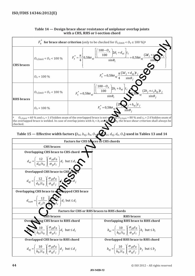
The design axial resistance of uniplanar overlap joints with a CHS, RHS, I or Hsection chord shall be determined using Table 13 and Table 14. Effective width factors (bei, bej, be,ov and dei, dej, de,ov) used in Tables 13 and 14 are given in Table 15.
Table 13 — Design axial resistance of uniplanar overlap joints with a CHS, RHS, I- or H-section chord
Limit state Axially loaded overlap joints
Local yielding of overlapping brace F ti i i
* = σ y b,eff.
Local chord member yieldingFF
MM
0 0 1 0pl,0
c
pl,0
+ ≤ ,
c = 1,7 for CHS chord
c = 1,0 for RHS or Isection chord
Brace sheara
(for Ov,limit < Ov ≤ 100 %)F F Fi i j jcos cos *θ θ+ ≤ s (see Table 14)
b,eff.
CHS braces RHS bracesSee Figure 4 c)
25 % ≤ Ov < 50 % b,eff. e e,ov= + + −( )π
42 4d d d ti i i
b,eff.v
e e,ov=
+ + −
Oh b b ti i i
502 4
50 % ≤ Ov < 100 % b,eff. i ei e,ov i= + + −2 4h b b t
Ov = 100 % b,eff. e,ov= + −( )π4
2 2 4d d ti i b,eff. e,ov= + + −2 4h b b ti i i
General note The efficiency (i.e. design resistance divided by the yield load) of the overlapped brace j shall not exceed that of the overlapping brace i
Range of validity
42 © ISO 2012 – All rights reservedXV-1439-13

IIW C
omm
ission
XV
revie
w pur
pose
s only
ISO/FDIS 14346:2012(E)
Limit state Axially loaded overlap joints
General
d / d d / d
b / b b / b
d / b d / b
i j
i j
i j
0 0
0 0
0 0
0 20
0 25
0
and
and
and
≥
≥
≥
,
,
,225
d d
b bi j
i j
/
/
≥
≥
0 75
0 75
,
,
t t t
t ti j
i j
and ≤
≤0
θ θi j and ≥ °30 Ov ≥ 25 %
σ σ σy y y0 and i j ≤ and σ σy u≤ 0 8,
Chord
CHSCompression class 1 or 2 and d t0 0/ ≤ 50
Tension d t0 0/ ≤ 50
RHS
Compression class 1 or 2 and / 40 and /0 0 0 0b t h t≤ ≤ 40
Tension b t h t0 0 0 0/ 40 and /≤ ≤ 40
Aspect ratio 0,5 /0 0≤ ≤h b 2 0,
I- or H-sec-
tion
CompressionFlange class 1 or 2Web class 1 or 2 and dw ≤ 400 mm
Tension NoneCHS or RHS chord I- or H-section chord
Braces
CHSCompression class 1 or 2 and d t1 1/ ≤ 50 class 1
Tension d t2 2/ ≤ 50
RHS
Compressionclass 1 or 2 and
b t h t1 1 1 1/ 40 and /≤ ≤ 40class 1
Tension b t h t2 2 2 2/ 40 and /≤ ≤ 40
Aspect ratio0,5 / and
0,5 /
≤ ≤≤ ≤h bh bi i
j j
2 0
2 0
,
,
h bh bi i
j j
/ and
/
==1 0
1 0
,
,
a Ov,limit = 60 % if the hidden seam of the overlapped brace is not welded; Ov,limit = 80 % if the hidden seam of the overlapped brace is welded.
Table 13 (continued)
© ISO 2012 – All rights reserved 43XV-1439-13
IIW C
omm
ission
XV
revie
w pur
pose
s only
ISO/FDIS 14346:2012(E)
Table 14 — Design brace shear resistance of uniplanar overlap joints with a CHS, RHS or I-section chord
Fs* for brace shear criterion (only to be checked for Ov,limit < Ov ≤ 100 %)a
CHS braces
Ov,limit < Ov < 100 % F
Od d t
i
i i i
ijs u
ve
u* ,
sin,
(=
−
+
+π4
0 58
100
1002
0 582
σθ
σdd c d tj j j
j
+
s e )
sinθ
Ov = 100 % Fd d t
jj j j
js u
e* ,( )
sin=
+0 58
4
3σ
θπ
RHS braces
Ov,limit < Ov < 100 % F
Oh b t
hi
i i i
ij
js u
ve
u* ,
sin,
(=
−
+
+0 58
100
1002
0 582
σθ
σ++ c b tj j
j
s e )
sinθ
Ov = 100 % Fh b b t
jj j j j
js u
e* ,sin
=+ +( )
0 582
σθ
a Ov,limit = 60 % and cs = 1 if hidden seam of the overlapped brace is not welded; Ov,limit = 80 % and cs = 2 if hidden seam of the overlapped brace is welded. In case of overlap joints with hi < bi and/or hj < bj, the brace shear criterion shall always be checked.
Table 15 — Effective width factors (bei, bej, be, Ov and dei, dej, de, Ov) used in Tables 13 and 14
Factors for CHS braces to CHS chordsCHS braces
Overlapping CHS brace to CHS chord
dd t
tt
d dii i
i ie0 0
y0
y/ but=
≤12 0σ
σ
Overlapped CHS brace to CHS chord
dd t
tt
d djj j
j je0 0
y0
y/ but=
≤12 0σ
σ
Overlapping CHS brace to overlapped CHS brace
dd t
tt
d dj j
j j
i ii ie,ov
y
y/ but=
≤12 σ
σ
Factors for CHS or RHS braces to RHS chordsCHS braces RHS braces
Overlapping CHS brace to RHS chord
db t
tt
d dii i
i ie0 0
y0
y/ but=
≤10 0σ
σ
Overlapping RHS brace to RHS chord
bb t
tt
b bii i
i ie0 0
y0
y/ but=
≤10 0σ
σ
Overlapped CHS brace to RHS chord
db t
tt
d djj j
j je0 0
y0
y/ but=
≤10 0σ
σ
Overlapped RHS brace to RHS chord
bb t
tt
b bjj j
j je0 0
y0
y
10
/ but=
≤
σσ
0
44 © ISO 2012 – All rights reservedXV-1439-13

IIW C
omm
ission
XV
revie
w pur
pose
s only
ISO/FDIS 14346:2012(E)
Overlapping CHS brace to overlapped CHS brace
dd t
tt
d dj j
j j
i ii ie,ov
y
y/ but=
≤12 σ
σ
Overlapping RHS brace to overlapped RHS brace
bb t
tt
b bj j
j j
i ii ie,ov
y
y/ but=
≤10 σ
σ
Factors for CHS or RHS braces to I-section chordsCHS braces RHS braces
Overlapping CHS brace to I-section chord
d t r t dei wy0
yii but= + + ≤2 7 0
σσ
Overlapping RHS brace to I-section chord
b t r t bei wy0
yii but= + + ≤2 7 0
σσ
Overlapped CHS brace to I-section chord
d t r t dej wy0
yjj but= + + ≤2 7 0
σσ
Overlapped RHS brace to I-section chord
b t r t bej wy0
yjj but= + + ≤2 7 0
σσ
Overlapping CHS brace to overlapped CHS brace
dd t
tt
d de,ovj j
yj j
yi ii i
/ but=
≤12 σ
σ
Overlapping RHS brace to overlapped RHS brace
bb t
tt
b be,ovj j
yj j
yi ii i
/ but=
≤10 σ
σ
Table 15 (continued)
© ISO 2012 – All rights reserved 45XV-1439-13

IIW C
omm
ission
XV
revie
w pur
pose
s only
ISO/FDIS 14346:2012(E)
Annex A (informative)
Quality requirements for hollow sections
A.1 The grade and quality of steel chosen shall meet static strength and toughness requirements, taking into account weldability, restraint, thickness, environmental conditions, rate of loading, extent of cold forming, and the consequence of failure.
A.2 For SHS and RHS made by coldforming which satisfy the requirements of Table A.1, the distance between the longitudinal seam and the tangent point to the external corner radius (ro) should be at least twice the wall thickness (2t), as shown in Figure A.1. In those cases where Table A.1 is not satisfied, this distance should be increased to at least 5t.
Keya longitudinal seam
Figure A.1 — Distance between the longitudinal seam and the tangent point to the external corner radius
A.3 For SHS and RHS, welding is permitted in the zones of cold forming if the following conditions (see Table A.1) of external corner radius are satisfied. These restrictions do not apply if heat-treatment has been performed on coldformed sections, to produce sections with compatible metallurgical properties to hot-finished sections.
46 © ISO 2012 – All rights reservedXV-1439-13
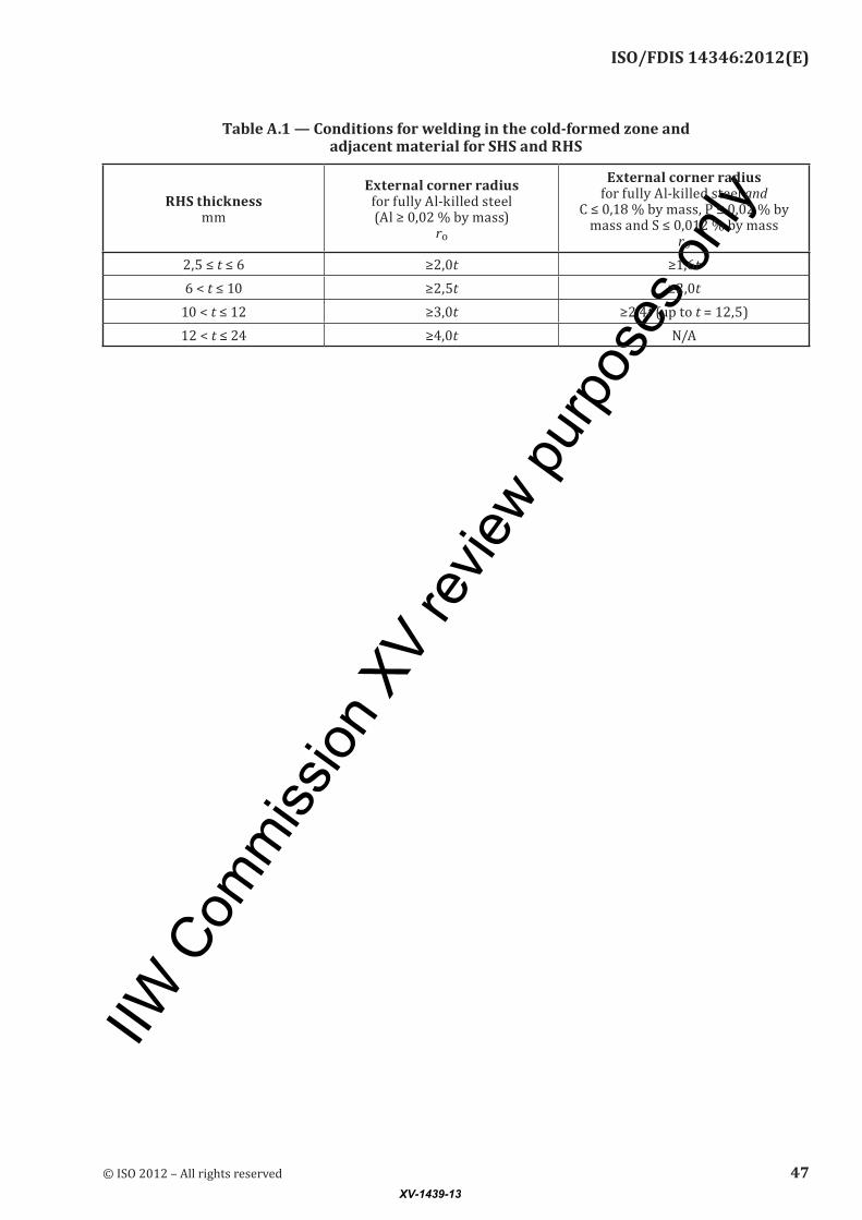
IIW C
omm
ission
XV
revie
w pur
pose
s only
ISO/FDIS 14346:2012(E)
Table A.1 — Conditions for welding in the cold-formed zone and adjacent material for SHS and RHS
RHS thickness mm
External corner radius for fully Alkilled steel (Al ≥ 0,02 % by mass)
ro
External corner radius for fully Alkilled steel and
C ≤ 0,18 % by mass, P ≤ 0,02 % by mass and S ≤ 0,012 % by mass
ro
2,5 ≤ t ≤ 6 ≥2,0t ≥1,6t6 < t ≤ 10 ≥2,5t ≥2,0t
10 < t ≤ 12 ≥3,0t ≥2,4t (up to t = 12,5)12 < t ≤ 24 ≥4,0t N/A
© ISO 2012 – All rights reserved 47XV-1439-13
IIW C
omm
ission
XV
revie
w pur
pose
s only
ISO/FDIS 14346:2012(E)
Annex B (informative)
Weld details
B.1 Except for K and Njoints with partially overlapped brace members (as covered in Clause 22 by reference to the hidden seam), connection shall be established around the entire perimeter of a hollowsection brace member by means of a full penetration weld, a partial penetration weld, a fillet weld or a combination.
B.2 Recommendations advocated in this specification are for welds produced to normal structural welding standards, such as ISO 5817.[23]
B.3 Welds shall satisfy one of the following conditions:
a) welds are to be proportioned to be “fit for purpose” and to resist forces in the connected members, taking account of joint deformation or rotation capacity and considering weld effective lengths;
b) welds are to be proportioned to achieve the capacity of the connected member walls — this will automatically prequalify the weld for any brace member loading.
B.4 For fillet welds:
a) the local dihedral angle at the toe of the brace shall not exceed 120°;
b) such welds are not generally recommended for wall thicknesses greater than 8 mm;
c) when such welds are not feasible at the saddle regions of circular hollowsection joints, partial or full penetration welds shall be provided there, while fillet welds may be used at the crown toe and crown heel regions.
B.5 Weld start and stop positions for noncontinuous welds should not be located at points of stress concentration. Some recommended locations for these weld start and stop positions are shown in Figure B.1.
48 © ISO 2012 – All rights reservedXV-1439-13

IIW C
omm
ission
XV
revie
w pur
pose
s only
ISO/FDIS 14346:2012(E)
Figure B.1 — Recommended weld start and stop positions
© ISO 2012 – All rights reserved 49XV-1439-13

IIW C
omm
ission
XV
revie
w pur
pose
s only
ISO/FDIS 14346:2012(E)
Annex C (informative)
Partial safety factors on static strength
C.1 The partial safety factors that have been used in this International Standard for the calculation of the design resistances for the various joint types are given in Table C.1.
C.2 The partial safety factors (γM) given in Table C.1 are approximately equivalent to the reciprocal of the ϕ factors for LSD (LRFD), i.e. γM is approximately 1/ϕ.
50 © ISO 2012 – All rights reservedXV-1439-13
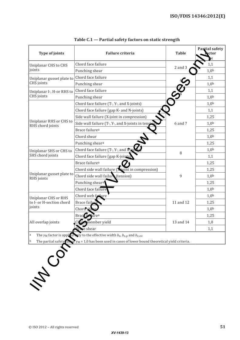
IIW C
omm
ission
XV
revie
w pur
pose
s only
ISO/FDIS 14346:2012(E)
Table C.1 — Partial safety factors on static strength
Type of joints Failure criteria TablePartial safety
factor γM
Uniplanar CHS to CHS joints
Chord face failure2 and 3
1,1Punching shear 1,0b
Uniplanar gusset plate to CHS joints
Chord face failure4
1,1Punching shear 1,0b
Uniplanar I, Hor RHS to CHS joints
Chord face failure4
1,1Punching shear 1,0b
Uniplanar RHS or CHS to RHS chord joints
Chord face failure (T, Y, and Xjoints)
6 and 7
1,0b
Chord face failure (gap K and Njoints) 1,1Side wall failure (Xjoint in compression) 1,25Side wall failure (T, Y, and Xjoints in tension) 1,0b
Brace failurea 1,25Chord shear 1,0b
Punching sheara 1,25
Uniplanar SHS or CHS to SHS chord joints
Chord face failure (T, Y, and Xjoints)8
1,0b
Chord face failure (gap Kjoints) 1,1
Uniplanar gusset plate to RHS joints
Brace failurea
9
1,25Chord side wall failure (Xjoint in compression) 1,25Chord side wall failure (tension) 1,0b
Punching sheara 1,25Chord face failure 1,0b
Uniplanar CHS or RHS to I or Hsection chord joints
Chord web failure11 and 12
1,0b
Brace failurea 1,25Chord shear 1,0b
All overlap jointsBrace failurea
13 and 141,25
Chord member yield 1,0Brace shear 1,1
a The γM factor is applied only to the effective width be, be,p and be,ov.b The partial safety factor γM = 1,0 has been used in cases of lower bound theoretical yield criteria.
© ISO 2012 – All rights reserved 51XV-1439-13
IIW C
omm
ission
XV
revie
w pur
pose
s only
ISO/FDIS 14346:2012(E)
Bibliography
[1] AISC. Load and resistance factor design specification for steel hollow structural sections. Chicago, IL: American Institute of Steel Construction, 2000. Available (viewed 20121112) at: http://gisceu.net/PDF/U187.pdf
[2] ANSI/AISC 36010, Specification for structural steel buildings. Available (viewed 20121112) at: http://www.aisc.org/WorkArea/showcontent.aspx?id=26516
[3] AWS D1.1/D1.1M: 2010, Structural welding code — Steel
[4] EN 199311, Eurocode 3: Design of steel structures — Part 1-1: General rules and rules for buildings
[5] EN 199318, Eurocode 3: Design of steel structures — Part 1-8: Design of joints
[6] EN 102102, Hot finished structural hollow sections of non-alloy and fine grain steels — Part 2: Tolerances, dimensions and sectional properties
[7] EN 102192, Cold formed welded structural hollow sections of non-alloy and fine grain steels — Part 2: Tolerances, dimensions and sectional properties
[8] Dutta D., Wardenier J., Yeomans N., Sakae K., Bucak Ö., Packer J.A.Design guide for fabrication, assembly and erection of hollow section structures. Cologne: Verlag TÜV Rheinland, 1998. (CIDECT Series: Construction with hollow steel sections, Vol. 7)
[9] Dutta D. Structures with hollow sections. Darmstadt: Ernst & Sohn, 2000
[10] IIW XV49181, Design recommendations for hollow section joints — Predominantly statically loaded
[11] IIW XV70189, Design recommendations for hollow section joints — Predominantly statically loaded
[12] IIW XV140212, Static design procedure for welded hollow section joints — Recommendations
[13] Kurobane Y., Packer J.A., Wardenier J., Yeomans N.Design guide for structural hollow section column connections. Cologne: Verlag TÜV Rheinland, 2004. (CIDECT Series: Construction with hollow steel sections, Vol. 9)
[14] Marshall P.W. Design of welded tubular connections — Basis and use of AWS code provisions. Amsterdam: Elsevier, 1992
[15] Packer J.A.Henderson J.E. Hollow structural section connections and trusses — A design guide. Toronto: Canadian Institute of Steel Construction, Second Edition, 1997
[16] Packer J.A., Sherman D.R., Lecce M. Hollow structural section connections. Chicago, IL: American Institute of Steel Construction, 2010. (Steel Design Guide, No. 24.)
[17] Packer J.A., Wardenier J., Zhao X.L., van der Vegte G.J., Kurobane Y.Design guide for rectangular hollow section (RHS) joints under predominantly static loading. Geneva: CIDECT, 2nd Edition, 2009. (CIDECT Series: Construction with hollow steel sections, Vol. 3)
[18] Sedlacek G., Völling B., Pak D., Feldmann M.Local buckling behaviour of coldformed RHS made from S1100. In: Proceedings of 11th International Symposium on Tubular Structures, Québec, Canada, 2006, pp. 147–152
[19] Wardenier J. Hollow section joints. Delft: Delft University Press, 1982
[20] Wardenier J., Kurobane Y., Packer J.A., van der Vegte G.J., Zhao X.LDesign guide for circular hollow section (CHS) joints under predominantly static loading. Geneva: CIDECT, 2nd Edition, 2008. (CIDECT Series: Construction with hollow steel sections, Vol. 1)
52 © ISO 2012 – All rights reservedXV-1439-13

IIW C
omm
ission
XV
revie
w pur
pose
s only
ISO/FDIS 14346:2012(E)
[21] Wardenier J., Packer J.A., Zhao X.L., van der Vegte G.J. Hollow sections in structural applications. Geneva: CIDECT, Second Edition, 2010
[22] Zhao X.L., Wardenier J., Packer J.A., van der Vegte G.J.New IIW ( 2008) static design recommendations for hollow section joints. In: Proceedings of 12th International Symposium on Tubular Structures, Shanghai, China, 2008, pp. 261270
[23] ISO 5817, Welding — Fusion-welded joints in steel, nickel, titanium and their alloys (beam welding excluded) — Quality levels for imperfections
© ISO 2012 – All rights reserved 53XV-1439-13

IIW C
omm
ission
XV
revie
w pur
pose
s only
ISO/FDIS 14346:2012(E)
© ISO 2012 – All rights reserved
ICS 25.160.40Price based on 53 pages
XV-1439-13