xpt/r-2g studio transmitter link - radiorelee tv si fm · pdf filexpt/r-2g studio transmitter...
TRANSCRIPT
XPT/R2G
Pag. 1
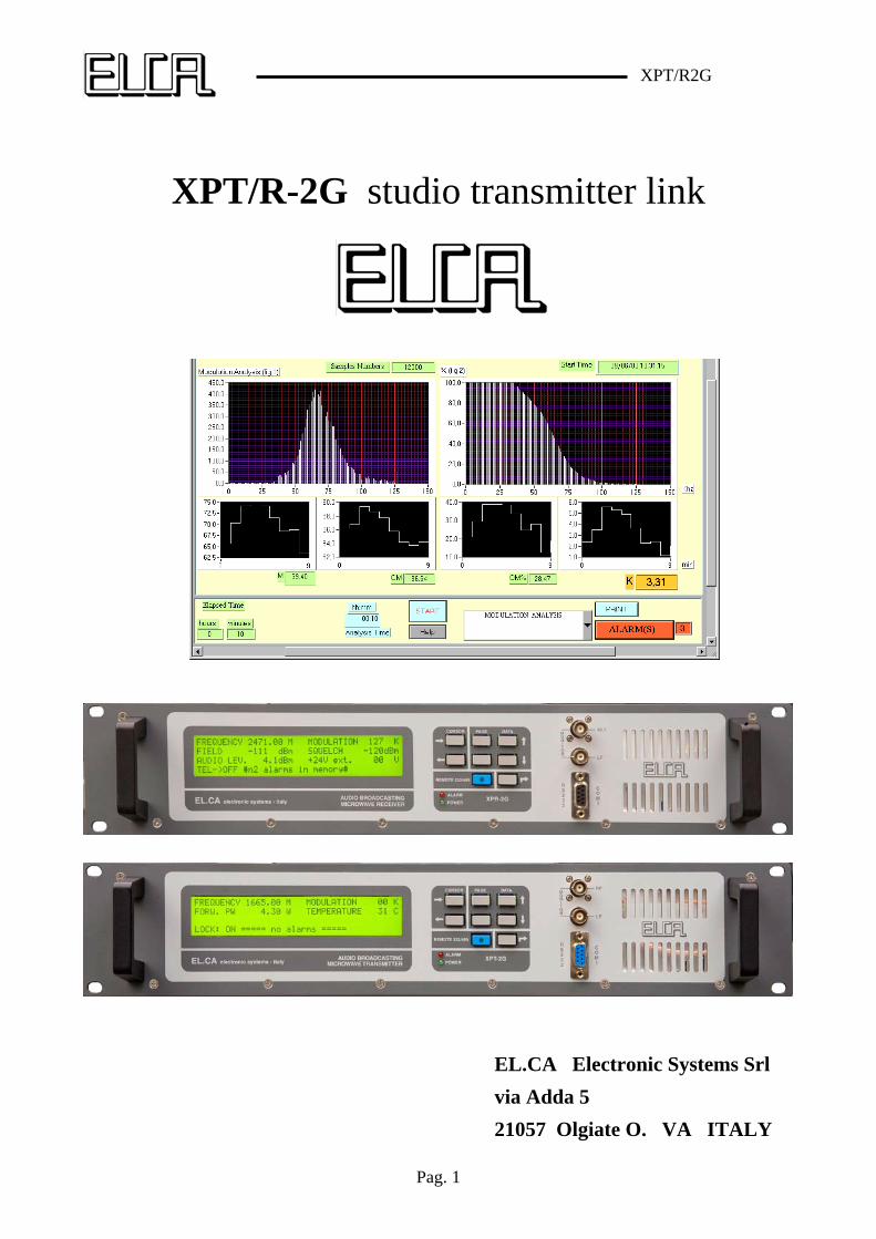
XPT/R-2G studio transmitter link
EL.CA Electronic Systems Srl
via Adda 5
21057 Olgiate O. VA ITALY
XPT/R2G
Pag. 2
XPT-2G STL TRANSMITTER
ELECTRICAL SPECIFICATION
2.1 FREQUENCY - POWER Frequency range ------------------------------------------------------- 1300 – 2600MHZ in 30 MHZ steps Frequency setting---------------------------------------------------------------------- in 50 or 100KHz steps Internal setting mode ------------------------------------------------------------------------------------ by keys External setting mode by remote control------------------------------------------- ( RS232-RS485-GSM ) Frequency stability ------------------------------------------------------------------------------- ±1000Hz/year Frequency generation --------------------------------------------------------------------------PLL synthesizer Modulation type ---------------------------------------------------------- direct VCO frequency modulation Nominal frequency deviation---------------------------------------------------------------------------±75kHz Deviation linearity in all frequency range ---------------------------------------------------------------±1dB Peak detector error ----------------------------------------------------------------------------------------<0.1dB RF output power----------------------------------------------------------------------------------------0 to 4.5W Power resolution setting------------------------------------------------------------------------------------ 0.1W Power control limit setting ---------------------------------------------------------------------------1 to 4.5W Power control stability-----------------------------------------------------------------------------------< 0.2dB Harmonics emission ------------------------------------------------------------------------------------ <-60dBc Spurious emission --------------------------------------------------------------------------------------- <-60dBc Carrier reduction power ( carrier enable off ) -------------------------------------------------------- >50dBc
2.2 MODULATION CAPABILITY MONO (left and right)-------------------------------------------------------------------------- 40Hz to 15kHz STEREO (by internal stereo generator) ------------------------------------------------------ 40Hz to 53kHz SCA (two channels)----------------------------------------------------------------------------40Hz to 100kHz COMPOSITE --------------------------------------------------------------------- MONO or STEREO + SCA
2.3 CHARACTERISTICS IN MONO Signal input ------------------------------------------------------------------------------------------Left + Right Input impedance -------------------------------------------------------------------- 600 (balanced) or 10k Unbalance rejection --------------------------------------------------------------------------------------- >40dB Input level -------------------------------------------------------------------------------------------0 to +12dBm Pre-emphasis -------------------------------------------------------------------------------------------75 or 50s Audio frequency response (30Hz to 15kHz) -------------------------------------------------------- <0.15dB Audio frequency response ( 19kHz to 100kHz)------------------------------------------------------ <-40dB Modulation distortion------------------------------------------------------------------------------------ <0.03% Signal to noise ratio --------------------------------------------------------------------------------------- >70dB
XPT/R2G
Pag. 3
2.4 CHARACTERISTICS IN STEREO Signal inputs ----------------------------------------------------------------------------------------Left or Right Input impedance -------------------------------------------------------------------- 600 (balanced) or 10k Unbalance rejection --------------------------------------------------------------------------------------- >40dB Input level -------------------------------------------------------------------------------------------0 to +12dBm Pre-emphasis -------------------------------------------------------------------------------------------75 or 50s Audio frequency response (40Hz to 15kHz) -------------------------------------------------------- <0.15dB Audio frequency response (19kHz to 100kHz) ------------------------------------------------------- <40dB Cross-talk between left and right channel-------------------------------------------------------------- >50dB Stereo separation between left and right channel ----------------------------------------------------- >50dB Distortion at frequency deviation of 75kHz ---------------------------------------------------------- <0.05% Distortion at frequency deviation of 100kHz--------------------------------------------------------- <0.05% Signal to noise referred at deviation of 75kHz -------------------------------------------------------- >70dB Suppression of 38KHz------------------------------------------------------------------------------------ >70dB Spurious suppression outside band ------------------------------------------ .in according to ETS 300-384 Pilot reference for RDS encoder (19 Khz out) ----------------------------------------------------------1Vpp
2.5 SCA CHARACTERISTICS Input (SCA1, SCA2)-------------------------------------------------------------------------- BNC unbalanced Input impedance -------------------------------------------------------------------------------------------- 10K Frequency response (50kHz to 100kHz) ---------------------------------------------------------------<0.1dB Distortion----------------------------------------------------------------------------------------------------<0.1% Modulation capability ----------------------------------------------------------------------------------0 to 10%
2.6 READOUT ON LCD DISPLAY (40x4 characters) Forward power resolution---------------------------------------------------------------------------------- 0.1W Modulation resolution -------------------------------------------------------------------------------------- 1kHz Power amplifier voltage resolution --------------------------------------------------------------------------1V Heatsink temperature resolution ----------------------------------------------------------------------------1°C
2.7 ALARMS ALARMS OUT ------------------- one reed contact for carrier enable internal power supply external power supply lock detect -3dB power down modulation absence SMS sending by GSM
XPT/R2G
Pag. 4
2.8 POWER SUPPLY AND TEMPERATURE RANGE Operating voltage ----------------------------------------------------------------------- 100 – 250VAC ±15 % Operating voltage DC -------------------------------------------------------------------- 20 – 28 Vdc ±10 % Line power ----------------------------------------------------------------------------------------------- <100VA Nominal temperature range --------------------------------------------------------------------------0° to 40°C Operating temperature range --------------------------------------------------------------------- -10° to 45°C Storage temperature range ----------------------------------------------------------------------- -40° to 50°C
2.9 MECHANICAL SPECIFICATION 19” rackmount -------------------------------------------------------------------------------- 485x135x530mm Weight ---------------------------------------------------------------------------------------------------------- 6kg
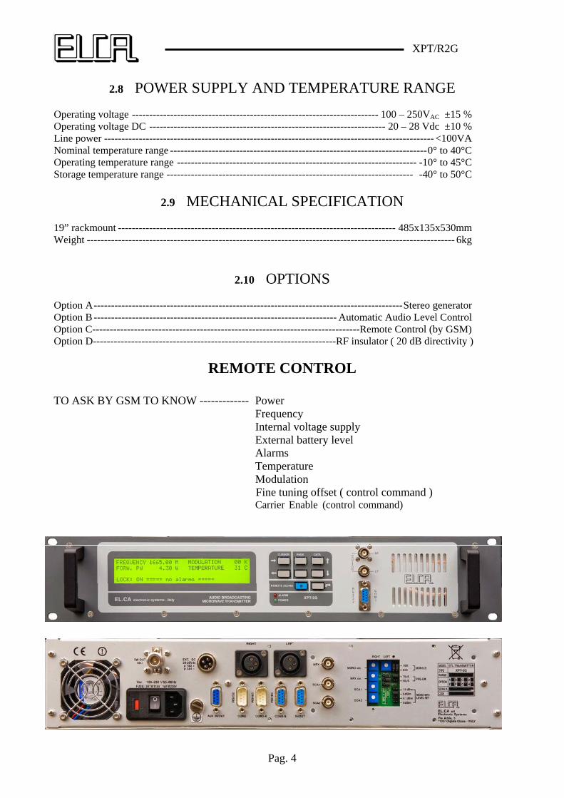
2.10 OPTIONS Option A-----------------------------------------------------------------------------------------Stereo generator Option B ---------------------------------------------------------------------- Automatic Audio Level Control Option C-----------------------------------------------------------------------------Remote Control (by GSM) Option D----------------------------------------------------------------------RF insulator ( 20 dB directivity )
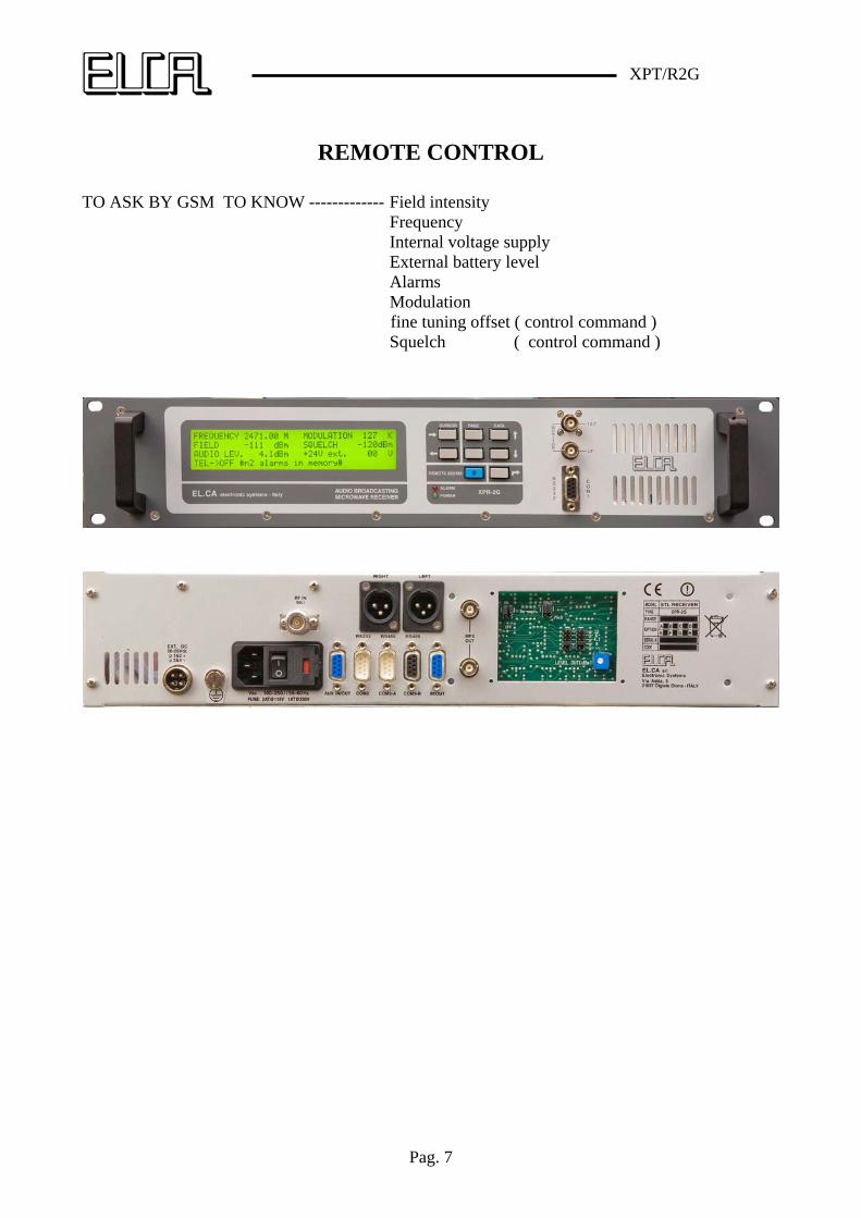
REMOTE CONTROL
TO ASK BY GSM TO KNOW ------------- Power Frequency Internal voltage supply External battery level Alarms Temperature Modulation Fine tuning offset ( control command ) Carrier Enable (control command)

XPT/R2G
Pag. 5
XPR-2G STL RECEIVER
ELECTRICAL SPECIFICATION
3.1 FREQUENCY Frequency range -------------------------------------------------------- 1300 – 2600MHZ in 30MHZ steps Frequency setting------------------------------------------------------------------------ in 50 or 100kHz steps Internal setting mode ------------------------------------------------------------------------------------ by keys External setting mode by remote control------------------------------------------- ( RS232-RS485-GSM ) Frequency stability ------------------------------------------------------------------------------- ±1000Hz/year Frequency generation --------------------------------------------------------------------------PLL synthesizer Nominal frequency deviation demodulation----------------------------------------------------------±75kHz Deviation linearity in all frequency range ---------------------------------------------------------------±1dB Peak detector error ----------------------------------------------------------------------------------------<0.1dB Squelch threshold ---------------------------------------------------------------------- -40/-100dBm Squelch threshold step ---------------------------------------------------------------------------- 1dB Max rf input signal -----------------------------------------------------------------------------20dBm
3.2 SELECTIVITY
RF input selectivity --------------------------------------------- 60 dB for +/- 140 Mhz of input frequency 3 dB IF band-width (static) ------------------------------------------------------------------------- +/-100kHz 40 dB IF band-width (static)------------------------------------------------------------------------ +/-400kHz 60 dB IF band-width (static------------------------------------------------------------------------- +/-800kHz Dinamic at +/- 100 KHz---------------------------------------------------------------------------------- -45dB Dinamic at +/- 200 KHz------------------------------------------------------------------------------------ -5dB Dinamic at +/- 600 KHz------------------------------------------------------------------------------------ 40dB Deviation linearity in all frequency range ---------------------------------------------------------------±1dB
3.3 MPX AUDIO OUTPUT Multiplex level ---------------------------------------------------------------------- 0, 4.1, 6, 12dBm Multiplex response 40Hz – 53kHz------------------------------------------------------------------ +/-0.2dB Multiplex response 53–75kHz----------------------------------------------------------------------- +/-1.5dB Multiplex response 75–100kHz ------------------------------------------------------------------------- - 4dB Multiplex response >115kHz------------------------------------------------------------------------- <-40dB Stereo separation 40Hz–5kHz --------------------------------------------------------------------------- >50dB Stereo separation 5–15kHz ------------------------------------------------------------------------------ >45dB Zout --------------------------------------------------------------------------------------------------------- <100
XPT/R2G
Pag. 6
Zload ------------------------------------------------------------------------------------------------------- >600S/N 40Hz–15kHz (L or R decoded and de-emph.) Vi>-40dBm ---------------------------------- >70dB S/N 40Hz–15kHz (L or R decoded and de-emph. CCIR) Vi>-40dBm ------------------------- > 65dB Harmonic distortion 40Hz–15kHz (L or R decoded and de-emph.) ----------------------------- <0.15%
3.4 LEFT AND RIGHT DECODED
Left and Right audio level ------------------------------------------------------------------------------ 6 dBm 40Hz–15kHz audio response ---------------------------------------------------------------------- +/- 0.15dB Zout ------------------------------------------------------------------------------------------------------- <100 Zload ------------------------------------------------------------------------------------------------------ >600 Stereo separation 40Hz–5kHz -------------------------------------------------------------------------- >40dB Stereo separation 5kHz–15kHz ------------------------------------------------------------------------ >35dB S/N 40Hz–15kHz (L or R decoded and de-emph.) Vi>-40 dBm --------------------------------- >70dB S/N 40Hz–15kHz (L or R decoded and de-emph. CCIR) Vi >-40 dBm -------------------------- >65dB Harmonic distortion (L or R decoded and de-emph.) Vi >-40 dBm -------------------------------< 0.2% Connectors ---------------------------------------------------------------------------------------- XLR
3.5 ALARMS ALARMS OUT ------------------------one reed contact for carrier detect internal power supply external power supply lock detect field intensity SMS sending by GSM
3.6 POWER SUPPLY AND TEMPERATURE RANGE
Operating voltage -------------------------------------------------------------------------100–250VAC ±15 % Operating voltage DC -----------------------------------------------------------------------20–28Vdc ±10 % Line power ------------------------------------------------------------------------------------------------ <50VA Nominal temperature range --------------------------------------------------------------------------0° to 40°C Operating temperature range --------------------------------------------------------------------- -10° to 45°C Storage temperature range ----------------------------------------------------------------------- -40° to 50°C
3.7 MECHANICAL SPECIFICATION 19” rackmount -------------------------------------------------------------------------------- 485x135x530mm Weight ---------------------------------------------------------------------------------------------------------- 5kg
3.8 OPTIONS Option A-------------------------------------------------------------------------------------------Stereo decoder Option C---------------------------------------------------------Remote Control (directly to PC or by GSM)
XPT/R2G
Pag. 7
REMOTE CONTROL
TO ASK BY GSM TO KNOW ------------- Field intensity Frequency Internal voltage supply External battery level Alarms Modulation fine tuning offset ( control command ) Squelch ( control command )
XPT/R2G
Pag. 8
XPT-2G GENERAL DESCRIPTION
XPT-2G is a FM band broadcasting transmitter with modern conceiving and technology, which by a simple design produces an output radio signal with high characteristics of quality, reliability and security.
The simple manufacturing obtained with a high integration of functions, has allowed to create a machine with few controls and connections. Most printed circuits are multilayer with a surface mounting technology component assembling. The eventual repairing can be done by simply changing the fault involved board, without searching the defective component.
One of the most important characteristics is the high quality of the frequency modulation and the high signal-to-noise ratio; moreover, the modulation is typically constant within 0.5dB throughout the whole assigned band (typically 10MHz width) .A proper peak detector allows to perform both traditional modulation measurements (usual bar-graph with peak), and modulation and power modulation ones with long observation periods (even with many hours or days) according to the latest international regulations, which properly cared to fix a limit scientifically measurable to the peak and modulation power (CEPT 54-01).
An particular audio circuit can control the input audio level with a ±6dB dynamics referred to the nominal value: this can be extremely useful when the audio signal level is not fixed or when this one can be subject to fluctuations (usually very slow) due to thermal driftsbad systems maintenance, possible damages along radio link paths etc. A proper board can be inserted to obtain this function and a proper microprocessor follows constantly the modulation value correcting through proper algorithms, implemented in its memory, the value of the modulator gain, keeping this way the modulation very close to the maximum allowed value. The corrections take place at very long periods of time; the board does not perform the audio compressing-limiting functions, but just compensates possible drifts occurring on the systems carrying the audio channel before entering in the FM transmitter. No measurable phase or amplitude distortion is introduced in the modulation when the automatic gain control circuit is enabled. In addition an alarm which switches the power off in case of modulation absence can be inserted since the unmodulated carrier transmission is forbidden in many countries, with no chance to identify the radio.
The transmitter can be set like a modern signals generator so the output power is completely managed by a device which guarantees that the values of forward power, maximum output power versus the temperature and loading conditions, are always the ones set or the ones allowed by maximum limits. A directional wide band coupler with remarkable directivity and large on board memory allows to obtain a power accuracy worthy of a good measurement instrument.
All parameters (frequency, levels, mono/stereo, pre-emphasis, power) can be set by the keyboard and stored in E2PROM in order to be kept even without electric supply. A great number of events can be stored: each alarm is distinguished by a starting and an ending alarm date. The controlled parameters are: modulation absence, heatsink temperature, mains supply voltage, RF power final stage voltage and current, main oscillator fault.
A second RS232 port placed in the rear part can be connected to a MODEM which is connected to the phone line thus assuring the transmitter telecontrol, remotely or from the studio.
The transmitter can be modulated by five different audio signal.
The first two ones are made by monophonic left and right channels, which can be balanced or unbalanced. The input dynamic goes from 0 to +12dBm with an input impedance which can be
XPT/R2G
Pag. 9
high or low. On these channels either the European or American pre-emphasis value can be inserted. A low pass filter on each of the two inputs assures a good attenuation of audio frequencies higher than 15KHz which could interfere, in case of stereophonic transmission, with higher band and with subcarrier of Multiplex signal; the out-of-band attenuation of the filter is not excessive in order not to increase then phase distortion (group delay) of the in band audio signal: 60–70dB attenuation, even with 0.1dB of amplitude linearity up to 15kHz, unavoidably creates a phase distortion on the analogue signal that an experienced ear can perceive. Right or left signals can be combined to generate monophonic transmission (should you only have one of the two signals, it will be necessary to externally connect in parallel the two inputs); in case of stereophonic transmission, the two channels are fed inside the stereo code board.
The mono signal or the stereo one, thus obtained, is combined with the other three possible input audio signals: an external Multiplex signal and two SCA signals, one of which can be the RDS one, which can be synchronized with a 19kHz one connected on the IN/OUT rear connector.
The composite signal can enter the AGC board, which has the task to check its amplitude and consequently to keep the modulation at the correct value, or it can follow its path and enter into the frequency modulator after having passed through a limiter circuit (CLIPPER). This circuit must became active just in cases of faults of previous circuits or in case of mistake in the setting of the low frequency input nominal levels; this is to avoid to interfere with the adjacent channels. To not activating this “fuse”, which produces remarkable distortions on the modulation, it is necessary to take all proper cautions, that is the use of external compressor-limiters or by inserting the internal AGC circuit which protects a lot against damages and drifts.
The oscillator, directly modulated by the composite signal, covers the whole assigned band and synthesized in steps of 50 or 100kHz . The reference frequency is obtained by a 10MHz crystal, whilst the output frequency is set by the main microcontroller. The oscillator phase noise is very good. The modulation linearity is typically contained within 0.5dB without complicated corrections.
The RF final power circuit is wide band and it provides 4.5 W RF output controlled with high accuracy; directional coupler has a directivity higher than 25dB on the whole band and an error which is lower than 0.2dB; it is also compensated in temperature and totally shielded.
The power supply is of a switching type and it gives the four essential voltages, all obtained with this technique. The mechanical position of the power supply and the final circuits of RF power allow to obtain a vent flu just for cooling the involved circuits, obtaining this way a really remarkable efficiency of that function. In normal running conditions, when the transmitter is working in a full power at environmental temperature, the radiator temperature is lower than 50°C, whereas the other circuits temperature does not exceed 40°C. No components are involved with the air flow, so it isn’t requested a filter on the aspiration fan, which replacing is rather simple. The power supply is completely shielded both for internal circuits and for its unavoidable emissions toward the outside.
Data displaying and setting is obtained by a board which is placed directly on the front panel containing a microprocessor, memory, keyboard, LCD display. The displaying area is wide so allowing to display and set needed data in a very easy way, thus making the transmitter-user technician interaction extremely user friendly.
It’s possible to protect the transmitter input and output parameter settings with a password, while all measurements can be done by whoever without interfering on its operation.
Maintenance or repairing of damages do not require the soldering use for the replacement of the parts to be changed; only six flat cables link all different boards.
XPT/R2G
Pag. 10
3.2 Available options
a) STEREO ENCODER : additional board allowing the internal encoding of the stereophonic signal
b) AGC : additional board allowing a frequency modulation
control c) REMOTE CONTROL : software for the GSM connection d) RF INSULATOR : 20 dB isolation from antenna reverse power
XPT/R2G
Pag. 11
XPR-2G GENERAL DESCRIPTION
The XPR-2G receiver is a modern, professional receiver created for the reception of frequency modulated signals and broadcasted in the range 1300–2600MHz .
The high selectivity of the input circuit, the intermediate frequency stages, and the accurate demodulation process, make it also ideal for signal repeating in the FM range.
The receiver’s electrical features are also guaranteed with input power signals of -20dBm, and it can withstand powers greater than 30dB without being damaged.
Where used in very crowded transmitting sites, before connecting the antenna, it’s recommended to ensure that the received signals are not stronger than the permitted ones; particular attention must be paid in verifying the transmitter signals available at the sites, which can include antennas placed on the same tower of the receiving one. It is not unusual to measure power levels reaching considerable number of watts at the receiving antenna.
Where received signals exceed permitted levels, various measures must be taken to ensure the receiver working under the best conditions.
The following solutions can be adopted to solve this issue:
a) Move the receiving antenna so it’s shielded from interfering signals b) Attenuate the antenna signal by 10-20dB where the useful signal level
allows it c) Apply a bandpass double cavity filter at the receiver’s input to increase
the selectivity
At the antenna input, the receiver is equipped with a highly selective four-cell filter. The bandwidth is ±20Mhz with reference to the tuned frequency, and the attenuation of the image frequency is greater than 55dB.
The next stage is composed of a broadband amplifier with low noise figure (NF=3dB) and high IP3. The gain (<20dB) and the low noise figure allow the receiver to recover losses in the input filter (approximately 3–4dB) and therefore to achieve a good sensitivity; with a monophonic signal, 10 microvolts are enough to achieve a signal-to-noise ratio greater than 60dB on the demodulated and deemphasized audio signal.
The signal, thus filtered and amplified, is fed to an high-level balanced mixer (13dB); the local oscillator, for conversion to 70Mhz, derives from a module previously used as a basis for transmitters and featuring a very low phase noise.
The LO frequency is 70Mhz lower than the received frequency, and the minimum programmable step is 50khz or 100kHz . A 10Mhz reference, thermally compensated, allows the operation within a wide range of temperatures (0 – 40°C).
At the mixer output, the signal is fed to a 10 Mhz bandpass active filter with a high IP3. The first intermediate frequency has three selective stages, which give an output signal that has a group delay inside the band (±150kHz) of less than 500 nanosecs. The gain for the three stages is only a few dB, but the task of this module is to clean the signal of any disturbance that the first input filter is unable to eliminate because too close to the carrier signal. The good noise figure at this stage doesn’t have significant effects on the receiver’s sensitivity.
The first IF filter is followed by an attenuator programmed by the AGC signal, allowing the next two stages keeping on working in a linear zone. Two linear phase ceramic filters placed
XPT/R2G
Pag. 12
between two amplifiers provide the right selectivity without introducing excessive distortions of the modulated signal, which definitely has a bandwidth higher than the window imposed by the filters. Accurately designed matching circuits ensure to keep an high quality of the signal, which will subsequently be demodulated.
At the output of this process, the signal is demodulated in amplitude to drive the AGC and the S-meter.
An amplitude limiter follows; at this point, the RF signal is ready for demodulation; in order to achieve high performance, the traditional analogue frequency demodulator was not selected; instead, a digital solution is adopted.
An additional conversion is made (10.7Mhz>700kHz) by means of a crystal oscillator and a passive balanced mixer; the second intermediate frequency signal is fed to a fast trigger. The output pulses of this stage have an average value that depends on the frequency modulation value; the connection is perfectly linear, and, using this method, a demodulator that requires no alignments and independent on selective circuits is obtained.
The RF signal is thus demodulated. The phase and amplitude distortion features of the audio signal depend almost solely on the RF filters, particularly the IF ones. However, the symmetrical distortions can be compensated.
An amplitude equalizer composed of an amplifier with a Zero restores the band flatness to 53kHz.
In addition to the MPX signal, the demodulated signal can also contain RDS or SCA signals up to a base band frequency of 100kHz; beyond this limit, everything must be eliminated because it would be a spurious signal in case of retransmission.
A elliptical filter with 100kHz cut frequency removes the spurious components of the demodulated signal.
Both the intermediate frequency filters and the low-pass filter introduce a phase variation on the demodulated signal; the stereophonic signal quality depends largely on the variation in the base band phase. It is therefore necessary to introduce a phase equalizer to obtain stereophonic separation greater than 50dB.
A peak-to-peak detector accurately measures the modulation; a piece of software can provide the user with all the information in accordance to the current regulations regarding this important parameter.
The MPX signal is fed to two output BNC connectors with programmable fixed levels of 0, 4. 1, 6 or 12dBm; the amplitude can be regulated by ±2dB around the fixed level.
The monophonic signal is obtained from the MPX signal by means of a 15kHz elliptical filter having a slope of 40dB at 19kHz.
The receiver can be equipped with a stereophonic decoder to provide an output with good level of separation (> 40 dB) of the LEFT and RIGHT channels.
The power supply is not provided with the traditional AC mains power transformer. A switching-mode power supply generates 24Vdc directly from the mains power, thus allowing the receiver to be used both in Europe and in the Americas without any modification.
In this manner, yield and weight have been improved as compared to traditional solutions.
An auxiliary power supply generates all the voltages required by the receiver.
The system is internally controlled by a digital card that is interfaced with a keyboard and a large 40x4 characters LCD display. Parameters can thus be easily set and read.
XPT/R2G
Pag. 13
On the front panel, there are two monitor outputs to allow the user to easily control the operation using a spectrum analyzer for the IF output, or an oscilloscope for the audio output.
The rear panel also includes a DB9 connector with alarm signals (carrier-detect, fault, etc.) , which can drive a diversity system.
The receiver can also be powered through an external 24 Vdc power supply, which can also be used in the presence of a mains power supply without any power consumption. AC/DC switching is immediate.
XPT/R2G
Pag. 14
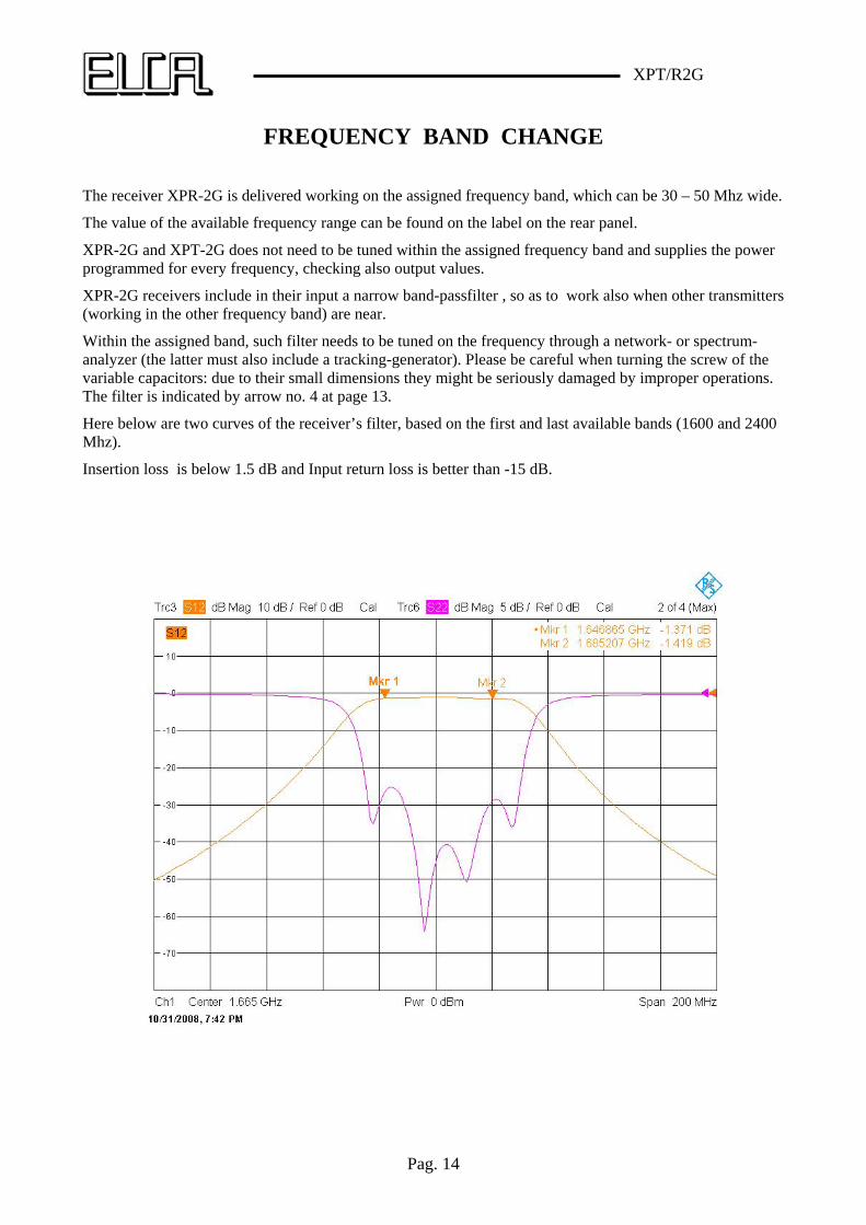
FREQUENCY BAND CHANGE The receiver XPR-2G is delivered working on the assigned frequency band, which can be 30 – 50 Mhz wide.
The value of the available frequency range can be found on the label on the rear panel.
XPR-2G and XPT-2G does not need to be tuned within the assigned frequency band and supplies the power programmed for every frequency, checking also output values.
XPR-2G receivers include in their input a narrow band-passfilter , so as to work also when other transmitters (working in the other frequency band) are near.
Within the assigned band, such filter needs to be tuned on the frequency through a network- or spectrum-analyzer (the latter must also include a tracking-generator). Please be careful when turning the screw of the variable capacitors: due to their small dimensions they might be seriously damaged by improper operations. The filter is indicated by arrow no. 4 at page 13.
Here below are two curves of the receiver’s filter, based on the first and last available bands (1600 and 2400 Mhz).
Insertion loss is below 1.5 dB and Input return loss is better than -15 dB.
XPT/R2G
Pag. 15
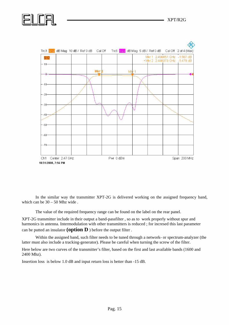
In the similar way the transmitter XPT-2G is delivered working on the assigned frequency band,
which can be 30 – 50 Mhz wide . The value of the required frequency range can be found on the label on the rear panel.
XPT-2G transmitter include in their output a band-passfilter , so as to work properly without spur and harmonics in antenna. Intermodulation with other transmitters is reduced ; for incresed this last parameter
can be putted an insulator (option D ) before the output filter .
Within the assigned band, such filter needs to be tuned through a network- or spectrum-analyzer (the latter must also include a tracking-generator). Please be careful when turning the screw of the filter.
Here below are two curves of the transmitter’s filter, based on the first and last available bands (1600 and 2400 Mhz).
Insertion loss is below 1.0 dB and input return loss is better than -15 dB.
XPT/R2G
Pag. 16
XPT/R2G
Pag. 17
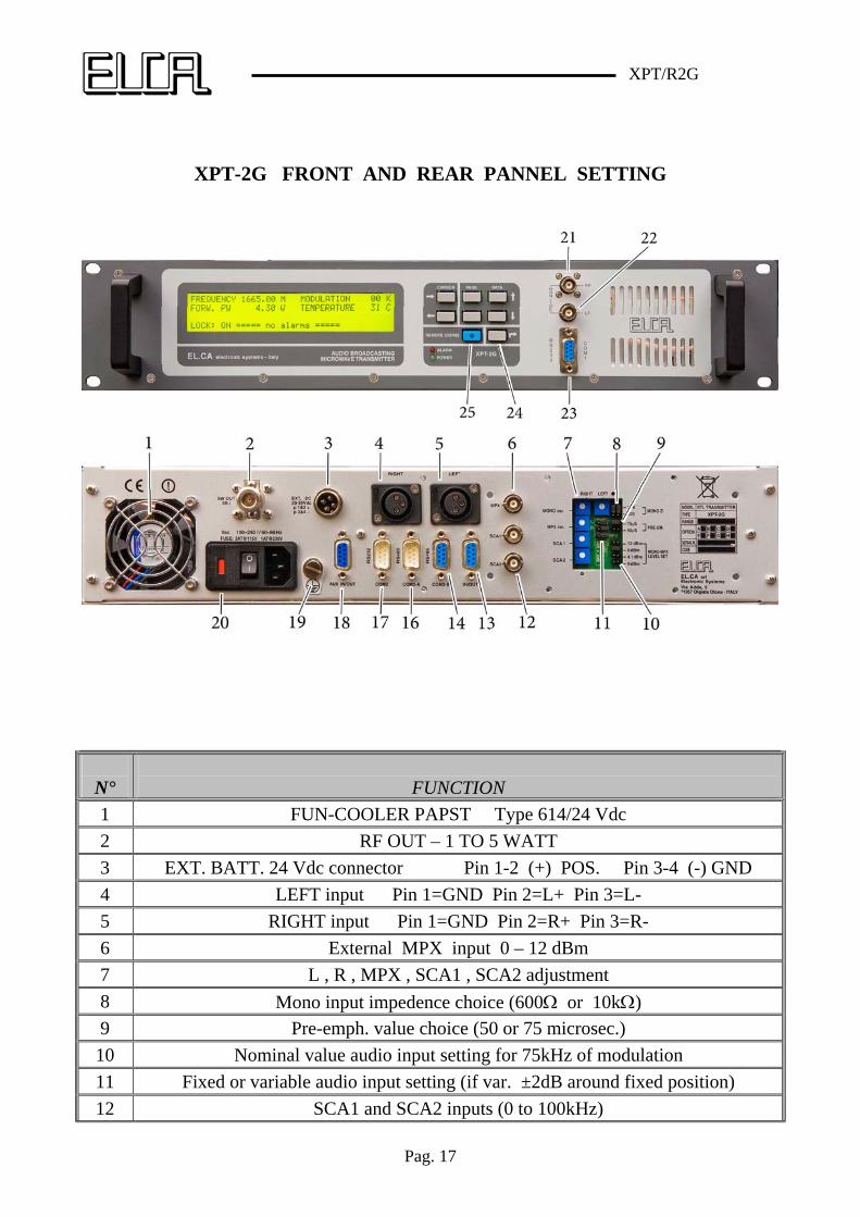
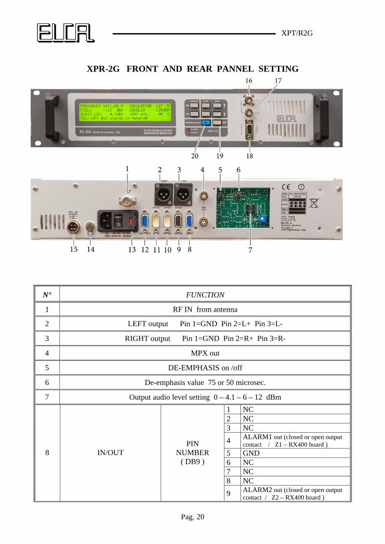
XPT-2G FRONT AND REAR PANNEL SETTING
N°
FUNCTION
1 FUN-COOLER PAPST Type 614/24 Vdc
2 RF OUT – 1 TO 5 WATT
3 EXT. BATT. 24 Vdc connector Pin 1-2 (+) POS. Pin 3-4 (-) GND
4 LEFT input Pin 1=GND Pin 2=L+ Pin 3=L-
5 RIGHT input Pin 1=GND Pin 2=R+ Pin 3=R-
6 External MPX input 0 – 12 dBm
7 L , R , MPX , SCA1 , SCA2 adjustment
8 Mono input impedence choice (600 or 10k)
9 Pre-emph. value choice (50 or 75 microsec.)
10 Nominal value audio input setting for 75kHz of modulation
11 Fixed or variable audio input setting (if var. ±2dB around fixed position)
12 SCA1 and SCA2 inputs (0 to 100kHz)
XPT/R2G
Pag. 18
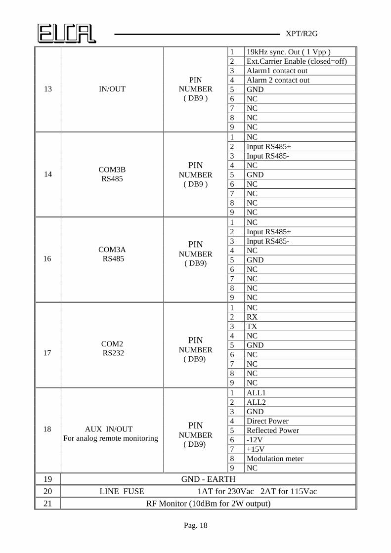
1 19kHz sync. Out ( 1 Vpp ) 2 Ext.Carrier Enable (closed=off) 3 Alarm1 contact out 4 Alarm 2 contact out 5 GND 6 NC 7 NC 8 NC
13 IN/OUT PIN
NUMBER ( DB9 )
9 NC 1 NC 2 Input RS485+ 3 Input RS485- 4 NC 5 GND 6 NC 7 NC 8 NC
14 COM3B RS485
PIN NUMBER
( DB9 )
9 NC 1 NC 2 Input RS485+ 3 Input RS485- 4 NC 5 GND 6 NC 7 NC 8 NC
16
COM3A RS485
PIN NUMBER
( DB9)
9 NC 1 NC 2 RX 3 TX 4 NC 5 GND 6 NC 7 NC 8 NC
17
COM2 RS232
PIN NUMBER
( DB9)
9 NC 1 ALL1 2 ALL2 3 GND 4 Direct Power 5 Reflected Power 6 -12V 7 +15V 8 Modulation meter
18
AUX IN/OUT For analog remote monitoring
PIN NUMBER
( DB9)
9 NC
19 GND - EARTH
20 LINE FUSE 1AT for 230Vac 2AT for 115Vac
21 RF Monitor (10dBm for 2W output)
XPT/R2G
Pag. 19
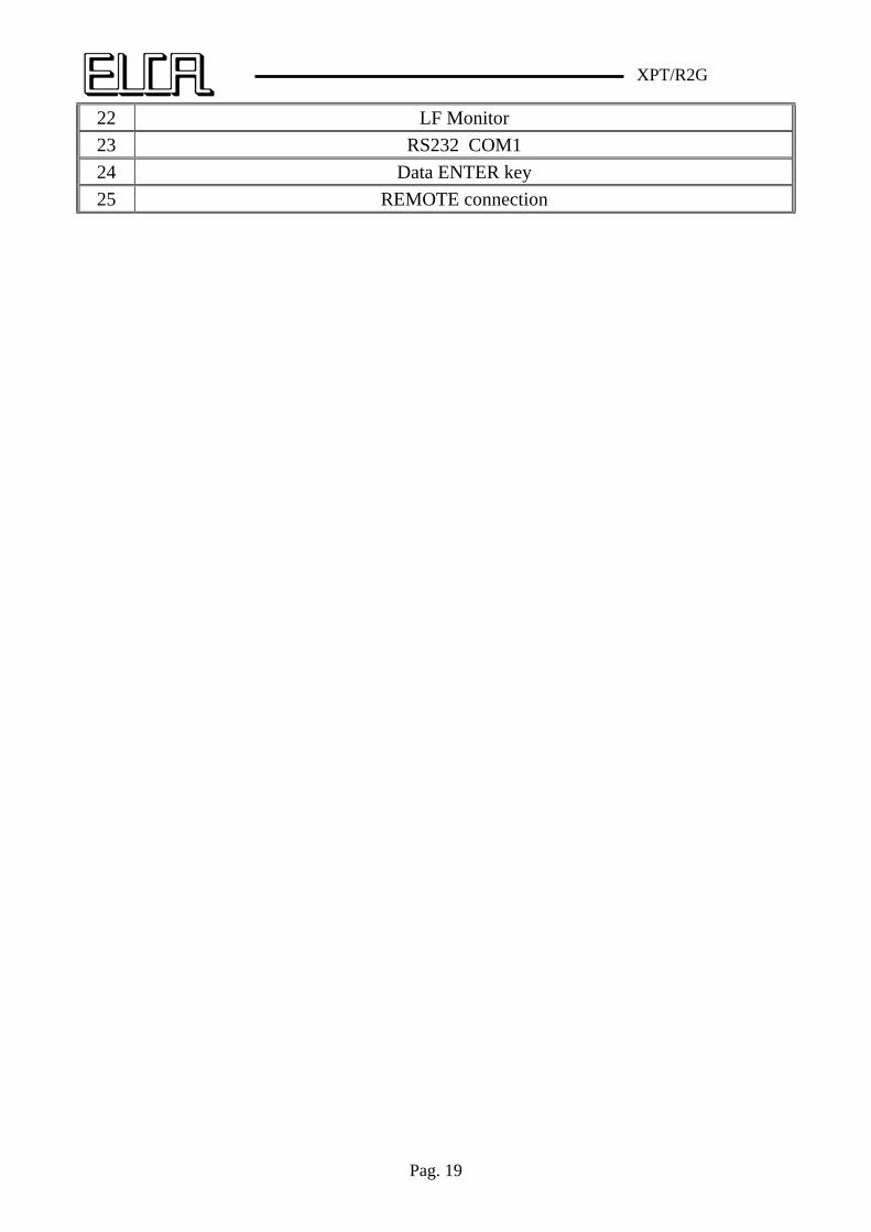
22 LF Monitor
23 RS232 COM1
24 Data ENTER key
25 REMOTE connection
XPT/R2G
Pag. 20
XPR-2G FRONT AND REAR PANNEL SETTING
N°
FUNCTION
1 RF IN from antenna
2 LEFT output Pin 1=GND Pin 2=L+ Pin 3=L-
3 RIGHT output Pin 1=GND Pin 2=R+ Pin 3=R-
4 MPX out
5 DE-EMPHASIS on /off
6 De-emphasis value 75 or 50 microsec.
7 Output audio level setting 0 – 4.1 – 6 – 12 dBm
1 NC 2 NC 3 NC
4 ALARM1 out (closed or open output contact / Z1 – RX400 board )
5 GND 6 NC 7 NC 8 NC
8 IN/OUT PIN
NUMBER ( DB9 )
9 ALARM2 out (closed or open output contact / Z2 – RX400 board )
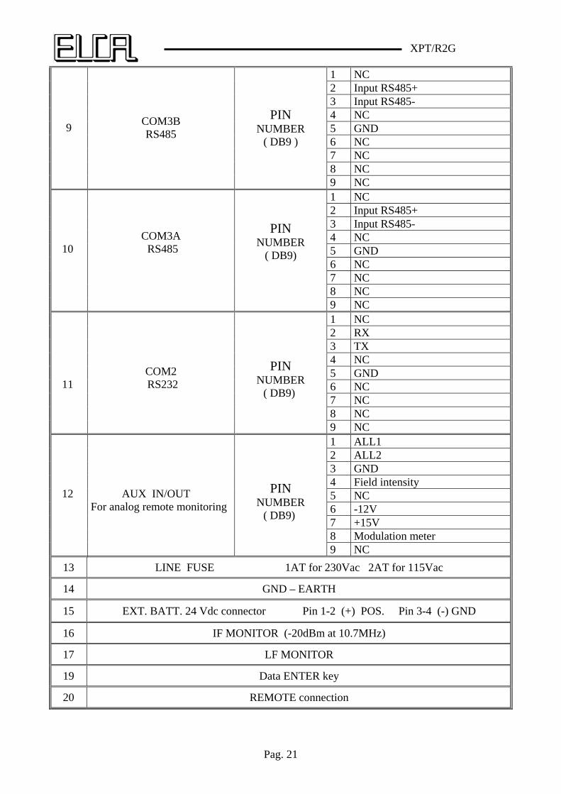
XPT/R2G
Pag. 21
1 NC 2 Input RS485+ 3 Input RS485- 4 NC 5 GND 6 NC 7 NC 8 NC
9 COM3B RS485
PIN NUMBER
( DB9 )
9 NC 1 NC 2 Input RS485+ 3 Input RS485- 4 NC 5 GND 6 NC 7 NC 8 NC
10
COM3A RS485
PIN NUMBER
( DB9)
9 NC 1 NC 2 RX 3 TX 4 NC 5 GND 6 NC 7 NC 8 NC
11
COM2 RS232
PIN NUMBER
( DB9)
9 NC 1 ALL1 2 ALL2 3 GND 4 Field intensity 5 NC 6 -12V 7 +15V 8 Modulation meter
12
AUX IN/OUT For analog remote monitoring
PIN NUMBER
( DB9)
9 NC
13 LINE FUSE 1AT for 230Vac 2AT for 115Vac
14 GND – EARTH
15 EXT. BATT. 24 Vdc connector Pin 1-2 (+) POS. Pin 3-4 (-) GND
16 IF MONITOR (-20dBm at 10.7MHz)
17 LF MONITOR
19 Data ENTER key
20 REMOTE connection
XPT/R2G
Pag. 22
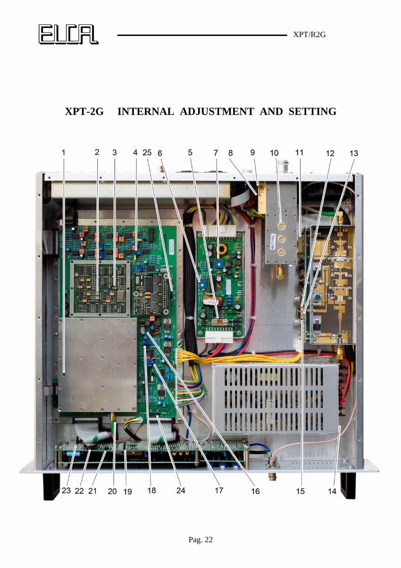
XPT-2G INTERNAL ADJUSTMENT AND SETTING
XPT/R2G
Pag. 23
N°
Board name/ Component
FUNCTION
DESCRIPTION
1 SINTG Mod. adj Adj. for 75kHz dF with right in level
2 DMPX Pilot level Adj. for 7.5kHz dF in Stereo mode
3 DMPX Pilot frequency Adj. for 19.000kHz
4 MBPN L / R balance Adjust for right balance at 1kHz
5 AL400 Ex Battery fuse 3A T
6 AL400 .+ 15Vdc Adjust to 15 Vdc on J1 connector pin 5
7 AL400 Temp. measure Adjust for right value displayed
8 ACC4G Power offset Adj for 0W out with 0W setted
9 ACC4G Power gain Adj for 4W out with 4W setted
10 ACC4G BPF. Adj on the out frequency by network-analyzer
11 A4GP RF Ampl. fuse 1.6A T
12 A4GP Max V rf ampl. Adj. for 10Vdc on the MGF0906 drain (rf ampl.)
13 A4GP Rf ampl drive curr Adj. for 0.2A on the MGF0905 drain
14 PW SUPPL.
Main pw. suppl. Adj. for 24Vdc out
15 A4GP Rf ampl. curr. Adj. for 0.4A on the MGF0906 drain
16 MBPN In.stereo level Adjust for 75kHz dF in stereo
17 MBPN Stereo Adjust for minimum st. separation at 1kHz
18 MBPN Stereo Adjust for minimum st. separation at 15kHz
19 DLCD Progr. Load. Run / Boot
20 SINTG Local Osc. out Ver. 10dBm out
21 DLCD Reset Press for master reset
22 DLCD CLK battery 3V3 litium
23 DLCD Password ON – OFF
24 MBPN Alarms out Closed or open output alarm contacts output
25 AGC Insertion ON / OFF
XPT/R2G
Pag. 24
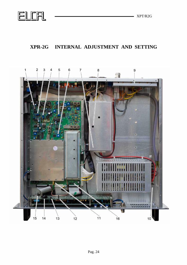
XPR-2G INTERNAL ADJUSTMENT AND SETTING
XPT/R2G
Pag. 25
N°
Board name/ Component
FUNCTION
DESCRIPTION
1 RX400 MPX level Adj. for 6dBm out when 6dBm is setted
2 LFO dF meas. Adj. for read 75kHz dF on display
3 RX400 St.separation Adj. for minimum at 15kHz on the L or R
4 RX400 St.separation Adj. for minimum at 1kHz on the L or R
5 RX400 Field meas. Adj for –90dBm RF input signal
6 RX400 Field meas. Adj for –50dBm RF input signal
7 AL400 Ex Batt.Fuse 2A T
8 AL400 15 Vdc Adj for 15Vdc on the J1 connector on pin 5
9 RF BPF RF filter Adj on the input frequency by network-analyzer
10 PW SUPPL. Main pw. suppl. Adj for 24Vdc out
11 SINTG Local Oscil. out Ver. 10dBm out
12 DLCD Prog .Load Run / Boot
13 DLCD
Reset Press for master reset
14 DLCD CLK battery 3V3 litium
15 DLCD Password ON - OFF
16 RX400 Alarms out Closed or open output alarm contacts output