xpsmcwin configuration software for xpsmc€¦ · · 2010-12-03document scope this manual...
TRANSCRIPT

3300
3281
.03
XPSMCWINConfiguration Software for XPSMC11/2007

2
Table of Contents
Safety Information . . . . . . . . . . . . . . . . . . . . . . . . . . . . . . . . . . . . 7
About the Book . . . . . . . . . . . . . . . . . . . . . . . . . . . . . . . . . . . . . . .9
Chapter 1 System Requirements and Software Installation . . . . . . . . . .11At a Glance . . . . . . . . . . . . . . . . . . . . . . . . . . . . . . . . . . . . . . . . . . . . . . . . . . . . . 11System Requirements. . . . . . . . . . . . . . . . . . . . . . . . . . . . . . . . . . . . . . . . . . . . . 12Installation . . . . . . . . . . . . . . . . . . . . . . . . . . . . . . . . . . . . . . . . . . . . . . . . . . . . . . 14
Chapter 2 XPSMCWIN User Interface . . . . . . . . . . . . . . . . . . . . . . . . . . . . . 15At a Glance . . . . . . . . . . . . . . . . . . . . . . . . . . . . . . . . . . . . . . . . . . . . . . . . . . . . . 15Window Types. . . . . . . . . . . . . . . . . . . . . . . . . . . . . . . . . . . . . . . . . . . . . . . . . . . 16Elements of a Window. . . . . . . . . . . . . . . . . . . . . . . . . . . . . . . . . . . . . . . . . . . . . 18
Chapter 3 Menu Commands . . . . . . . . . . . . . . . . . . . . . . . . . . . . . . . . . . . . 19At a Glance . . . . . . . . . . . . . . . . . . . . . . . . . . . . . . . . . . . . . . . . . . . . . . . . . . . . . 19File. . . . . . . . . . . . . . . . . . . . . . . . . . . . . . . . . . . . . . . . . . . . . . . . . . . . . . . . . . . . 20Edit . . . . . . . . . . . . . . . . . . . . . . . . . . . . . . . . . . . . . . . . . . . . . . . . . . . . . . . . . . . 21Mode . . . . . . . . . . . . . . . . . . . . . . . . . . . . . . . . . . . . . . . . . . . . . . . . . . . . . . . . . . 22Check . . . . . . . . . . . . . . . . . . . . . . . . . . . . . . . . . . . . . . . . . . . . . . . . . . . . . . . . . 23Controller. . . . . . . . . . . . . . . . . . . . . . . . . . . . . . . . . . . . . . . . . . . . . . . . . . . . . . . 24Options . . . . . . . . . . . . . . . . . . . . . . . . . . . . . . . . . . . . . . . . . . . . . . . . . . . . . . . . 27Help. . . . . . . . . . . . . . . . . . . . . . . . . . . . . . . . . . . . . . . . . . . . . . . . . . . . . . . . . . . 28Diagnostics . . . . . . . . . . . . . . . . . . . . . . . . . . . . . . . . . . . . . . . . . . . . . . . . . . . . . 29
Chapter 4 Device Library . . . . . . . . . . . . . . . . . . . . . . . . . . . . . . . . . . . . . . . 31At a Glance . . . . . . . . . . . . . . . . . . . . . . . . . . . . . . . . . . . . . . . . . . . . . . . . . . . . . 31
4.1 Controller. . . . . . . . . . . . . . . . . . . . . . . . . . . . . . . . . . . . . . . . . . . . . . . . . . . . . . . 33At a Glance . . . . . . . . . . . . . . . . . . . . . . . . . . . . . . . . . . . . . . . . . . . . . . . . . . . . . 33Creating a Configuration . . . . . . . . . . . . . . . . . . . . . . . . . . . . . . . . . . . . . . . . . . . 34Setting the Safety Outputs . . . . . . . . . . . . . . . . . . . . . . . . . . . . . . . . . . . . . . . . . 47Connecting a Device to a Safety Output . . . . . . . . . . . . . . . . . . . . . . . . . . . . . . . 49Modifying the Properties . . . . . . . . . . . . . . . . . . . . . . . . . . . . . . . . . . . . . . . . . . . 50
3
4.2 Monitoring Devices . . . . . . . . . . . . . . . . . . . . . . . . . . . . . . . . . . . . . . . . . . . . . . . 51At a Glance . . . . . . . . . . . . . . . . . . . . . . . . . . . . . . . . . . . . . . . . . . . . . . . . . . . . . 51Overview of all Control Devices. . . . . . . . . . . . . . . . . . . . . . . . . . . . . . . . . . . . . . 52Emergency Stop . . . . . . . . . . . . . . . . . . . . . . . . . . . . . . . . . . . . . . . . . . . . . . . . . 54Safety Guards . . . . . . . . . . . . . . . . . . . . . . . . . . . . . . . . . . . . . . . . . . . . . . . . . . . 55Light Curtains (Electro Sensitive Protective Equipment (ESPE)) of Category 4 without Muting . . . . . . . . . . . . . . . . . . . . . . . . . . . . . . . . . . . . . . . . . . 58Light Curtain with Muting . . . . . . . . . . . . . . . . . . . . . . . . . . . . . . . . . . . . . . . . . . . 60Magnetic Switch. . . . . . . . . . . . . . . . . . . . . . . . . . . . . . . . . . . . . . . . . . . . . . . . . . 65Two-Hand Control . . . . . . . . . . . . . . . . . . . . . . . . . . . . . . . . . . . . . . . . . . . . . . . . 66Safety Mat . . . . . . . . . . . . . . . . . . . . . . . . . . . . . . . . . . . . . . . . . . . . . . . . . . . . . . 67Zero Speed Detection . . . . . . . . . . . . . . . . . . . . . . . . . . . . . . . . . . . . . . . . . . . . . 69Injection Molding Machine . . . . . . . . . . . . . . . . . . . . . . . . . . . . . . . . . . . . . . . . . . 76Hydraulic Press Valve Monitoring . . . . . . . . . . . . . . . . . . . . . . . . . . . . . . . . . . . . 78Hydraulic Press 2. . . . . . . . . . . . . . . . . . . . . . . . . . . . . . . . . . . . . . . . . . . . . . . . . 80Eccentric Press . . . . . . . . . . . . . . . . . . . . . . . . . . . . . . . . . . . . . . . . . . . . . . . . . . 84Eccentric Press 2. . . . . . . . . . . . . . . . . . . . . . . . . . . . . . . . . . . . . . . . . . . . . . . . . 88Shaft/Chain Break Monitoring . . . . . . . . . . . . . . . . . . . . . . . . . . . . . . . . . . . . . . . 94Seat Valve Monitoring . . . . . . . . . . . . . . . . . . . . . . . . . . . . . . . . . . . . . . . . . . . . . 95
4.3 EDM Devices . . . . . . . . . . . . . . . . . . . . . . . . . . . . . . . . . . . . . . . . . . . . . . . . . . . . 97EDM Device (External Device Monitoring). . . . . . . . . . . . . . . . . . . . . . . . . . . . . . 97
4.4 Start Device . . . . . . . . . . . . . . . . . . . . . . . . . . . . . . . . . . . . . . . . . . . . . . . . . . . . . 98Start Device . . . . . . . . . . . . . . . . . . . . . . . . . . . . . . . . . . . . . . . . . . . . . . . . . . . . . 98
4.5 Enabling Devices . . . . . . . . . . . . . . . . . . . . . . . . . . . . . . . . . . . . . . . . . . . . . . . . 100Two-Channel or Three-Channel Enabling Device . . . . . . . . . . . . . . . . . . . . . . . 100
4.6 Miscellaneous Devices . . . . . . . . . . . . . . . . . . . . . . . . . . . . . . . . . . . . . . . . . . . 103At a Glance . . . . . . . . . . . . . . . . . . . . . . . . . . . . . . . . . . . . . . . . . . . . . . . . . . . . 103Timer . . . . . . . . . . . . . . . . . . . . . . . . . . . . . . . . . . . . . . . . . . . . . . . . . . . . . . . . . 104OR Device . . . . . . . . . . . . . . . . . . . . . . . . . . . . . . . . . . . . . . . . . . . . . . . . . . . . . 106Foot Switch Control Device . . . . . . . . . . . . . . . . . . . . . . . . . . . . . . . . . . . . . . . . 107Selector Switch . . . . . . . . . . . . . . . . . . . . . . . . . . . . . . . . . . . . . . . . . . . . . . . . . 109Closed Tool Device . . . . . . . . . . . . . . . . . . . . . . . . . . . . . . . . . . . . . . . . . . . . . . 112
4.7 State of Outputs . . . . . . . . . . . . . . . . . . . . . . . . . . . . . . . . . . . . . . . . . . . . . . . . . 113Applying Output States to Other Safety Outputs . . . . . . . . . . . . . . . . . . . . . . . . 113
4

Chapter 5 Configuration . . . . . . . . . . . . . . . . . . . . . . . . . . . . . . . . . . . . . . 115At a Glance . . . . . . . . . . . . . . . . . . . . . . . . . . . . . . . . . . . . . . . . . . . . . . . . . . . . 115
5.1 General Information. . . . . . . . . . . . . . . . . . . . . . . . . . . . . . . . . . . . . . . . . . . . . . 117Generals . . . . . . . . . . . . . . . . . . . . . . . . . . . . . . . . . . . . . . . . . . . . . . . . . . . . . . 117
5.2 Application Scheme Configuration . . . . . . . . . . . . . . . . . . . . . . . . . . . . . . . . . . 119At a Glance . . . . . . . . . . . . . . . . . . . . . . . . . . . . . . . . . . . . . . . . . . . . . . . . . . . . 119Creating a New Configuration / Selecting a Controller Type. . . . . . . . . . . . . . . 120Assigning the Switch Position . . . . . . . . . . . . . . . . . . . . . . . . . . . . . . . . . . . . . . 124Assigning the Protective Guard Function . . . . . . . . . . . . . . . . . . . . . . . . . . . . . 125Assigning the Starting Function. . . . . . . . . . . . . . . . . . . . . . . . . . . . . . . . . . . . . 126Assigning the Enabling Device . . . . . . . . . . . . . . . . . . . . . . . . . . . . . . . . . . . . . 127EDM Adjustment . . . . . . . . . . . . . . . . . . . . . . . . . . . . . . . . . . . . . . . . . . . . . . . . 128Assign a Name and a Stop Category to a Safety Output . . . . . . . . . . . . . . . . . 129Copying the State of One Safety Output onto another Safety Output. . . . . . . . 130
5.3 Configuring the Emergency Stop Function . . . . . . . . . . . . . . . . . . . . . . . . . . . . 131At a Glance . . . . . . . . . . . . . . . . . . . . . . . . . . . . . . . . . . . . . . . . . . . . . . . . . . . . 131Emergency Stop . . . . . . . . . . . . . . . . . . . . . . . . . . . . . . . . . . . . . . . . . . . . . . . . 132Master E-Stop Device . . . . . . . . . . . . . . . . . . . . . . . . . . . . . . . . . . . . . . . . . . . . 136
5.4 Save the Configuration . . . . . . . . . . . . . . . . . . . . . . . . . . . . . . . . . . . . . . . . . . . 137Save . . . . . . . . . . . . . . . . . . . . . . . . . . . . . . . . . . . . . . . . . . . . . . . . . . . . . . . . . 137
5.5 Requesting/Changing the Password. . . . . . . . . . . . . . . . . . . . . . . . . . . . . . . . . 139Password. . . . . . . . . . . . . . . . . . . . . . . . . . . . . . . . . . . . . . . . . . . . . . . . . . . . . . 139
5.6 Sending a Configuration from the PC to the XPSMC and Performing a Check . . . . . . . . . . . . . . . . . . . . . . . . . . . . . . . . . . . . . . . . . . . . . . . . . . . . . . . 141Sending a Configuration . . . . . . . . . . . . . . . . . . . . . . . . . . . . . . . . . . . . . . . . . . 141
5.7 Loading a Configuration . . . . . . . . . . . . . . . . . . . . . . . . . . . . . . . . . . . . . . . . . . 149Loading . . . . . . . . . . . . . . . . . . . . . . . . . . . . . . . . . . . . . . . . . . . . . . . . . . . . . . . 149
5.8 Creation/Transfer of a Validated Configuration Copy . . . . . . . . . . . . . . . . . . . . 151At a Glance . . . . . . . . . . . . . . . . . . . . . . . . . . . . . . . . . . . . . . . . . . . . . . . . . . . . 151Copy/Saving of a Validated Configuration. . . . . . . . . . . . . . . . . . . . . . . . . . . . . 152Transfer of a Validated Configuration Copy . . . . . . . . . . . . . . . . . . . . . . . . . . . 153
5.9 Read Protocol from Controller. . . . . . . . . . . . . . . . . . . . . . . . . . . . . . . . . . . . . . 155Read Protocol from Controller. . . . . . . . . . . . . . . . . . . . . . . . . . . . . . . . . . . . . . 155
Chapter 6 Diagnosis. . . . . . . . . . . . . . . . . . . . . . . . . . . . . . . . . . . . . . . . . . 157XPSMC Safety Controller Diagnostics . . . . . . . . . . . . . . . . . . . . . . . . . . . . . . . 157
5
Appendices . . . . . . . . . . . . . . . . . . . . . . . . . . . . . . . . . . . . . . . . . . . . . . 161At a glance. . . . . . . . . . . . . . . . . . . . . . . . . . . . . . . . . . . . . . . . . . . . . . . . . . . . . 161
Appendix A Wiring (Examples) and Functional Diagrams . . . . . . . . . . . . 163At a Glance . . . . . . . . . . . . . . . . . . . . . . . . . . . . . . . . . . . . . . . . . . . . . . . . . . . . 163Electrical Diagram for the XPSMC. . . . . . . . . . . . . . . . . . . . . . . . . . . . . . . . . . . 165Three One-Channel Emergency Stops, with Automatic Start . . . . . . . . . . . . . . 167Two Two-Channel Emergency Stop, with Start Button . . . . . . . . . . . . . . . . . . . 169Safety Guard with One Channel . . . . . . . . . . . . . . . . . . . . . . . . . . . . . . . . . . . . 171Two Channel Safety Guard . . . . . . . . . . . . . . . . . . . . . . . . . . . . . . . . . . . . . . . . 174Two Channels Safety Guard with Lock . . . . . . . . . . . . . . . . . . . . . . . . . . . . . . . 178Light Curtain with Relay Outputs . . . . . . . . . . . . . . . . . . . . . . . . . . . . . . . . . . . . 182Light Curtain with Transistor Outputs. . . . . . . . . . . . . . . . . . . . . . . . . . . . . . . . . 186Muting for Light Curtains Type 4 . . . . . . . . . . . . . . . . . . . . . . . . . . . . . . . . . . . . 190Magnetic Switch. . . . . . . . . . . . . . . . . . . . . . . . . . . . . . . . . . . . . . . . . . . . . . . . . 192Two-Hand Control . . . . . . . . . . . . . . . . . . . . . . . . . . . . . . . . . . . . . . . . . . . . . . . 196Safety Mat . . . . . . . . . . . . . . . . . . . . . . . . . . . . . . . . . . . . . . . . . . . . . . . . . . . . . 198Zero Speed Detection . . . . . . . . . . . . . . . . . . . . . . . . . . . . . . . . . . . . . . . . . . . . 200Injection Molding Machines . . . . . . . . . . . . . . . . . . . . . . . . . . . . . . . . . . . . . . . . 204Hydraulic Press Valve Monitoring . . . . . . . . . . . . . . . . . . . . . . . . . . . . . . . . . . . 207Hydraulic Press 2. . . . . . . . . . . . . . . . . . . . . . . . . . . . . . . . . . . . . . . . . . . . . . . . 209Eccentric Press . . . . . . . . . . . . . . . . . . . . . . . . . . . . . . . . . . . . . . . . . . . . . . . . . 215Eccentric Press 2. . . . . . . . . . . . . . . . . . . . . . . . . . . . . . . . . . . . . . . . . . . . . . . . 219Selector Switch . . . . . . . . . . . . . . . . . . . . . . . . . . . . . . . . . . . . . . . . . . . . . . . . . 224Timer . . . . . . . . . . . . . . . . . . . . . . . . . . . . . . . . . . . . . . . . . . . . . . . . . . . . . . . . . 226Shaft/Chain-Break Monitoring. . . . . . . . . . . . . . . . . . . . . . . . . . . . . . . . . . . . . . 229Seat Valve Monitoring . . . . . . . . . . . . . . . . . . . . . . . . . . . . . . . . . . . . . . . . . . . . 231Enabling Device 2 Channel . . . . . . . . . . . . . . . . . . . . . . . . . . . . . . . . . . . . . . . . 233Enabling Device 3 Channel . . . . . . . . . . . . . . . . . . . . . . . . . . . . . . . . . . . . . . . . 235Foot Switch . . . . . . . . . . . . . . . . . . . . . . . . . . . . . . . . . . . . . . . . . . . . . . . . . . . . 237
Glossary . . . . . . . . . . . . . . . . . . . . . . . . . . . . . . . . . . . . . . . . . . . . . . 239
Index . . . . . . . . . . . . . . . . . . . . . . . . . . . . . . . . . . . . . . . . . . . . . . 241
6

§
Safety InformationImportant Information
NOTICE Read these instructions carefully, and look at the equipment to become familiar with the device before trying to install, operate, or maintain it. The following special messages may appear throughout this documentation or on the equipment to warn of potential hazards or to call attention to information that clarifies or simplifies a procedure.
The addition of this symbol to a Danger or Warning safety label indicatesthat an electrical hazard exists, which will result in personal injury if theinstructions are not followed.
This is the safety alert symbol. It is used to alert you to potential personalinjury hazards. Obey all safety messages that follow this symbol to avoidpossible injury or death.
DANGER indicates an imminently hazardous situation, which, if not avoided, will result in death or serious injury.
DANGER
WARNING indicates a potentially hazardous situation, which, if not avoided, can result in death, serious injury, or equipment damage.
WARNING
CAUTION indicates a potentially hazardous situation, which, if not avoided, can result in injury or equipment damage.
CAUTION
33003281 7

Safety Information
PLEASE NOTE Electrical equipment should be installed, operated, serviced, and maintained only by qualified personnel. No responsibility is assumed by Schneider Electric for any consequences arising out of the use of this material.
© 2006 Schneider Electric. All Rights Reserved.
8 33003281

About the Book
At a Glance
Document Scope This manual contains the XPSMCWIN software description.
This program allows you to start, set up and diagnose the XPSMC safety controller from a PC.
The simple user interface lets you set up the XPSMC for a multitude of applications for the protection of hazardous areas near mechanical machines.
The XPSMCWIN software is used for the installation, documentation and fault diagnostics of your safety application.
Validity Note Eight versions of the safety controller are available:
Type Characteristics
XPSMC16Z 8 control outputs and 16 safety inputs6 safety transistor outputs2 x 2 safety relay outputsadd-in functionsModbus (RTU) communication and configuration port
XPSMC16ZP 8 control outputs and 16 safety inputs6 safety transistor outputs2 x 2 safety relay outputsadd-in functionsProfibus DP communication portModbus (RTU) communication and configuration port
XPSMC16ZC 8 control outputs and 16 safety inputs6 safety transistor outputs2 x 2 safety relay outputsadd-in functionsCANopen communication portModbus (RTU) communication and configuration port
33003281 9

About the Book
This documentation is valid for XPSMCWIN under Microsoft Windows 2000/XP.
Related Documents
You can download these technical publications and other technical information from our website at www.telemecanique.com
User Comments We welcome your comments about this document. You can reach us by e-mail at [email protected]
XPSMC16X 8 control outputs and 16 safety inputs6 safety transistor outputs2 x 2 safety relay outputsModbus (RTU) communication and configuration port
XPSMC32Z 8 control outputs and 32 safety inputs6 safety transistor outputs2 x 2 safety relay outputsadd-in functionsModbus (RTU) communication and configuration port
XPSMC32ZP 8 control outputs and 32 safety inputs6 safety transistor outputs2 x 2 safety relay outputsadd-in functionsProfibus DP communication portModbus (RTU) communication and configuration port
XPSMC32ZC 8 control outputs and 32 safety inputs6 safety transistor outputs2 x 2 safety relay outputsadd-in functionsCANopen communication portModbus (RTU) communication and configuration port
XPSMC32X 8 control outputs for 32 safety inputs6 safety transistor outputs2 x 2 safety relay outputsModbus (RTU) communication and configuration port
Type Characteristics
Title of Documentation Reference Number
XPSMC - Hardware Manual 33003275
10 33003281

33003281
1
System Requirements and Software InstallationAt a Glance
Overview This chapter contains the system requirements for the software and hardware.
What's in this Chapter?
This chapter contains the following topics:
Topic Page
System Requirements 12
Installation 14
11

System Requirements and Software Installation
System Requirements
Hardware The following is required for configuring the XPSMC safety controller:� XPSMC safety controller� PC with the following capabilities at least
� Pentium® processor, or equivalent� CD-ROM drive for the installation� mouse� free RS232 serial port with a 9-pin subD connector or USB-Port� 20 MB free hard disk space
� display: 800 x 600, 256 colors (1024 x 768 recommended)� configuration cable
� serialXPSMCCPC adaptorTSXPCX1031 serial adaptor
or� USB
standard (1:1) RJ45/RJ45 twisted pair Category 5D Ethernet cable Ref: 490NTW00002TSXCUSB485 USB adaptor
Connection between the PC and the XPSMC Safety Controller
To set up and diagnose the XPSMC for faults with the XPSMCWIN software, you must establish either
� a serial connection from the PC to the XPSMC safety controller.The following 2 cabling components are required to set up the connection� XPSMCCPC adaptor� TSXPCX1031 serial adaptoror
� an USB connection from the PC to the XPSMC safety controller.The following 2 cabling components are required to set up the connection� Standard (1:1) RJ45/RJ45 twisted pair Category 5D Ethernet cable Ref:
490NTW00002� TSXCUSB485 USB adaptor
Software The following are system requirements for the XPSMCWIN software:� Operating system: Microsoft® Windows 2000/XP®
12 33003281

System Requirements and Software Installation
Installing the USB Driver for the TSXCUSB485 Cable
The following table describes steps to install the USB driver for the TSXCUSB485 cable:
Step Action
1 Download the driver from the Web site http://www.telemecanique.com and search for USB Driver.Note: Additionally, the driver pack can be found on the Safety Suite V2 installation CD, within the ...XPSMC Safety Controller\XPSMC Drivers for cable folder.
2 Double click on ...Driver Pack V2.3.
3 Run the Communication_Drivers_Pack_V23.exe.file.
4 Plug in the cable.
5 Select Look for an adequate driver.
6 Select Other sources.
7 Select the location of the driver on the hard disk.
8 The driver is installed.
33003281 13

System Requirements and Software Installation
Installation
Installation Procedure
To install the XPSMCWIN software, you need the installation CD-ROM (included). If your PC does not have a CD-ROM drive, you can also copy the installation files on floppy disks and perform the installation. Proceed as follows:
Step Action
1 Insert the CD with the current version of the Safety Suite (included) into the drive. Follow the installation wizard instructions to install the software.
2 In case installation does not start automatically, run the setup.exe file in the CD-ROM default directory, for example:D:\setup.exe (if D: is the letter corresponding to your CD-ROM drive).
3 The program is ready to be started for the first time
14 33003281

33003281
2
XPSMCWIN User InterfaceAt a Glance
Overview This chapter contains the description of the software user interface.
What's in this Chapter?
This chapter contains the following topics:
Topic Page
Window Types 16
Elements of a Window 18
15

XPSMCWIN User Interface
Window Types
Introduction Typical XPSMCWIN user interface window
The items 1 to 5 have the following meanings:
Item Meaning
1 Menu bar
2 Tool bar
3 Device library window
4 Configuration window
5 Status bar
File Edit Mode Check Controller Options Help
XPSMCWIN
Device Library: Configuration:
i i
Configuration Mode Configuration changed. Com1
Configuration
C1 (XPSMC16 X): ’Controller1’i16
o1
o2
o3
o4
o5
o6
R1
R2
Telemecanique
Inputs: left: 16 I Load: 0 %
i
16
XPSMC16 ZC - CANopen Extension
EDM Devices
Start Devices
Miscellaneous Devices
Enabling Devices
Controller
State of Outputs
XPSMC16 Z
XPSMC16 ZP - Profibus Extension
XPSMC16 X
XPSMC32 Z32
XPSMC32 ZC - CANopen Extension32
XPSMC32 ZP - Profibus Extension32
XPSMC32 X32
16
16
16
Monitoring Devices
1
5
3 42
i
i
i
i
i
i
i
i
16 33003281

XPSMCWIN User Interface
Device Library Window
This window contains the eight possible types of controllers (XPSMC16Z, XPSMC16ZC, XPSMC16ZP, XPSMC16X, XPSMC32Z, XPSMC32ZC, XPSMC32ZP, and XPSMC32X) and the library of all devices available.
A device is copied from this library into the Configuration window by pressing and holding down the left mouse button and simultaneously dragging the mouse.
Configuration Window
This is the working window in XPSMCWIN. The configuration is defined and modified in this window.
All devices are configured by the following similar procedure.
If a device is moved in the Configuration window, a window appears in which the parameters of this device are selected. On the subject of these parameters, reference should also be made to chapter Device Library, p. 31.
The following commands can also be called by clicking the right mouse button on the symbol in the Configuration window:
Note: If this window does not open automatically, this means that this device is not active in the Options editor menu option. In this case, open the window by clicking with the right mouse button on the symbol and selecting the Properties option.
Command Description
Properties Open the Properties window of the selected device.
Copy Using this command, a device can be copied with the properties assigned to it and pasted elsewhere in the configuration tree.
Cut Cut the selected device.
Paste Paste a copied or cut device as a copy or as a new device into the selected location.
Delete Delete the selected object.
Delete incl. copies Delete the selected object and its copies.
Mark copies Mark all the copies of the selected device.
Unmark copies Clear all the copies of the selected device.
Expand all Expand the entire configuration tree.
Expand controller Expand the selected controller tree (only visible when more than one controller are in the current configuration).
Collapse all Collapse the entire configuration tree. Only controller will be shown.
33003281 17

XPSMCWIN User Interface
Elements of a Window
Menu Bar The menu bar contains all the commands of the XPSMCWIN software as shown in the structure overview below.
Menu bar for Configuration mode
Menu bar for Configuration mode (continued)
Menu bar for Diagnostics mode
File
New
Open...
Save
Print Tree
as you see it
all nodes expanded
Exit
Edit
Undo
Redo
Copy
Paste
Delete
Mode
Configuration
Diagnostics
Check
CheckConfiguration
Save As... Cut
Controller
Stop Controller
Run Controller
Change Password
Download Configuration to Controller
Upload Configuration from Controller
Get Validated Copy from Controller
Transfer Validated Copy to Controller
Read Validation
Read Protocol from Controller
Controller Setup (Bus Configuration)
Modbus...
Download Setup to Controller
COM Settings...
Options
Editor...
Language
Deutsch
English
Français
Italiano
Español
Português
Help
Contents....
About...Library...
Show all devices
Show only devices applicable for
CANopen...
Profibus...
Open Protocol
Controller Info
Validated Copy
MC16ZC - CANopen Extension
MC16ZP - Profibus Extension
MC16X
MC32Z
MC32ZC - CANopen Extension
MC32ZP - Profibus Extension
MC16Z
MC32X
File
Print Tree
as you see it
all nodes expanded
Diagnostics
Start diagnostics
Pause diagnostics
Mode
Configuration
Diagnostics
Options
Editor...
Language
Deutsch
English
Français
Italiano
Español
Português
Help
Contents...
About...
Exit
18 33003281

33003281
3
Menu CommandsAt a Glance
Overview This chapter contains the description of the menu commands.
What's in this Chapter?
This chapter contains the following topics:
Topic Page
File 20
Edit 21
Mode 22
Check 23
Controller 24
Options 27
Help 28
Diagnostics 29
19

Menu Commands
File
New Click New to create a new configuration. When this command is called, a new window appears in which the name and the author of this configuration can be indicated. A message box appears for saving an existing configuration if a configuration is already opened.
To enable opening the Properties dialog window automatically, after you drag and drop a device onto the Configuration window, select option automatically open properties dialog if a new device is dropped onto configuration in Editor on the Options menu.
Open Click Open to open a file selection popup menu. Here you can select an existing configuration. Additionally a backup file is created in the same directory with .mcb extension.
Save Click Save to save the current configuration under the current name.
Save As... Click Save As... to save the current configuration under a new name.
Print Tree Click Print Tree to print the configuration, and choose one of the following options:
Exit Click Exit to quit the XPSMCWIN software. If changes have been made to the configuration, you will be asked whether you want to save changes before quitting the program.
Option Meaning
as you see it The configuration tree will be printed as you see it in the configuration window.
all the nodes expanded The configuration tree will be printed with all the nodes expanded.
20 33003281

Menu Commands
Edit
Undo Click Undo to cancel the last action. You can repeat the step up to 10 times in a row.
Redo Click Redo to restore a cancelled action. You can repeat the step up to 10 times in a row.
Copy Click Copy to copy the selected item to the internal clipboard.
Cut Click Cut to cut the selected device.
Paste Click Paste to paste an item from the internal clipboard to the selected location, and choose one of the following options.
Delete Click Delete to delete the selected item.
Option Meaning
as a copy of the device The device will be copied with the properties of the source device (e.g., the same input and output) if the same hardware is connected to different inputs and outputs of the XPSMC.
as a device The device will be copied with its default properties. Alternatively, you can drag the device to the selected location.
33003281 21

Menu Commands
Mode
Configuration The Configuration mode is the software’s working mode. All the commands can be executed in this mode. In the Configuration mode, a configuration is created, modified, and sent to or reloaded from XPSMC. When the program is started, this is the default mode of the software.
Diagnostics The Diagnostics mode is used exclusively for diagnosing the XPSMC connected to the PC. The configuration cannot be modified. In the Diagnostic mode, the software working windows are grey in color.
In this mode, the connected XPSMC safety controller continues to operate without being affected.
22 33003281

Menu Commands
Check
Check Configuration
Use this command to check if the configuration is correct, before you download it into the XPSMC.
33003281 23

Menu Commands
Controller
Stop Controller Click Stop Controller to stop the XPSMC. Its safety outputs are de-activated in accordance with their stop category, (either immediately or with a delay). The password must be entered.
Run Controller Click Run Controller to change the XPSMC to Run mode.
Change Password
Click Change Password to open a window in which you can change the password. Beforehand, you will receive a message saying the controller has been stopped
Download Configuration to Controller
Click Download Configuration to Controller to send the current configuration to the selected controller. Prior to it, you will receive a message that the controller has been stopped. The password must be entered.
Note: Please bear in mind that when the configuration is downloaded, all outputs will be deactivated.
Upload Configuration from Controller
Click Upload Configuration from Controller to load the configuration to the PC and display the current configuration of the connected XPSMC. The XPSMC is still running at the same time.
Create Validated Copy from Controller
Click Create Validated Copy from Controller to create a file as safety copy of a validated configuration.
Transfer Validated Copy to Controller
Click Transfer Validated Copy to Controller to transfers a validated configuration to a controller.
Read Validation Click Read Validation to provide the date of validation and the name of the person who performed the validation of the connected XPSMC configuration.
Read Protocol from Controller
Click Read Protocol from Controller to upload the protocol of the current configuration and present it in a text (not ASCII) format. It allows you to store the protocol on your PC or to print it out. Before you use the command, stop the XPSMC and enter your password. Restart the XPSMC after you have closed the protocol.
Note: As the protocol is read from the Controller, all outputs are deactivated.
24 33003281

Menu Commands
Open Protocol Click Open Protocol to open a locally stored copy of the protocol and print it out. The file is read-only, and you cannot modify it.
Controller Setup (Bus Configuration)
Click Controller Setup (Bus Configuration), and choose one of the following options:
Download Setup to Controller
Click Download Setup to Controller to send the parameters set (for all communication protocols, i.e. Modbus (RTU), CANopen, Profibus DP) to the selected controller of this configuration. The XPSMC must also be stopped. The password must be entered.
Option Meaning
Modbus (RTU)
Opens a window for adjusting the settings required for the operation of all the XPSMCs (up to 8) of this configuration with a MODBUS system. Operation with different MODBUS systems is also possible. By clicking the Download button, the Send the settings to the controller command is executed. The settings are applicable to all controllers.
CANopen Opens a window with address and baud rate.
Profibus DP Opens a window with address only.
Note: This command causes only the bus communication parameters to be sent and not the configuration!
33003281 25

Menu Commands
Controller Info Click Controller Info to display the information about the type of controller, the firmware version, and the controller status.
To view information about the current firmware version of the Controller 1, Controller 2, and the fieldbus, click Details:
COM Selection... Choose COM Selection... to select the COM port (1...16) of the PC to which the XPSMC is connected.
Controller Info
Controller
Type: XPS-MC32 ZC
Firmware version: 2.30
Extension: CANopen Details...
Communication parameters
Modbus: Addr. 1, 19200 bit/s, 8 E
CANopen: Addr. 2, 1 Mbit/s
State
The controller is in RUN mode.
Configuration
The controller contains a validated configuration.Configuration validated by TESTLAB on ***ERROR: validation date corrupted***.
OKRefresh
26 33003281

Menu Commands
Options
Editor... Click Editor... to open the Editor Options dialog box, which allows you to check the automatically open properties dialog if a new device is dropped to configuration function.
Library Click Library , and select one of the following options:
Language Click Language to select the XPSMCWIN software language.
The software switches automatically to the selected language.
Option Meaning
Show all devices All devices are shown.
Show only devices applicable for Only the applicable devices of the XPSMC model are shown.
33003281 27

Menu Commands
Help
Contents... Click Contents... to view an overview of the online help.
About... Click About... to view information about the present version of the software.
28 33003281

Menu Commands
Diagnostics
Start Diagnostics The transmission of the diagnostics data from the XPSMC to the PC will be started.
Stop Diagnostics The transmission of the diagnostics data from the XPSMC to the PC will be stopped.
Note Switching into the diagnostic mode, with menu command Mode → Diagnostics, the menu bar will be modified like described in the chapter Elements of a Window, p. 18.
33003281 29

Menu Commands
30 33003281

33003281
4
Device LibraryAt a Glance
Overview This chapter contains the description of all the functionalities of the XPSMC. These functionalities are contained in the Device Library window in the configuration software.
What's in this Chapter?
This chapter contains the following sections:
Section Topic Page
4.1 Controller 33
4.2 Monitoring Devices 51
4.3 EDM Devices 97
4.4 Start Device 98
4.5 Enabling Devices 100
4.6 Miscellaneous Devices 103
4.7 State of Outputs 113
31

Device Library
32 33003281

Device Library
4.1 Controller
At a Glance
Overview The folder Controller contains the 8 types of controllers: XPSMC16Z, XPSMC16ZC, XPSMC16ZP, XPSMC16X, XPSMC32Z, XPSMC32ZC, XPSMC32ZP, and XPSMC32X.
What's in this Section?
This section contains the following topics:
Topic Page
Creating a Configuration 34
Setting the Safety Outputs 47
Connecting a Device to a Safety Output 49
Modifying the Properties 50
33003281 33

Device Library
Creating a Configuration
Introduction To create a configuration, click File → New.
Response Time You have the possibility to select a reponse time for the XPSMC16Z, XPSMC16ZC, XPSMC16ZC, XPSMC32Z, XPSMC32ZC, XPSMC32ZC devices. You can select 20 or 30 ms for the response times. With the longer response time you can configure more functionality in the device.
In the XPSMC16X and the XPSMC32X this possibility does not exist. Here the reponse time is always 20 ms.
Note: The following examples are for 16 input controllers only. The procedure for 32 input controllers is the same, if it is not otherwise stated.
34 33003281
Device Library
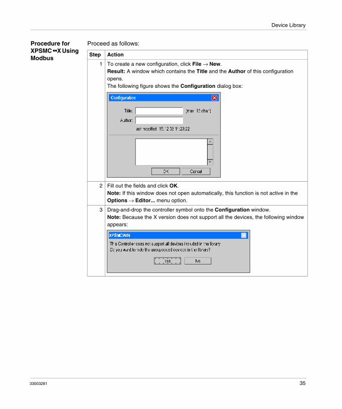
Procedure for XPSMC ••X Using Modbus
Proceed as follows:
Step Action
1 To create a new configuration, click File → New.Result: A window which contains the Title and the Author of this configuration opens.The following figure shows the Configuration dialog box:
2 Fill out the fields and click OK.Note: If this window does not open automatically, this function is not active in the Options → Editor... menu option.
3 Drag-and-drop the controller symbol onto the Configuration window. Note: Because the X version does not support all the devices, the following window appears:
Configuration
| (max. 16 char.)Title:
Author:
last modified: 15.12.03 11:23:22
OK Cancel
Yes No
This Controller does not support all devices included in the library.
XPSMCWIN
Do you want to hide the unsupported devices in the library?
33003281 35

Device Library
4 Select No to see all devices in the library. You can also make this selection in the Options menu.Result: A dialog box with Modbus marking appears.The following figure shows the Controller C1 (XPSMC16 X) dialog box:
5 Click change... to modify bus parameters.Result: The Modbus parameters dialog box appears.The following figure shows the Modbus Parameters dialog box:
This window also opens when all the other controllers in this configuration are added. Enter all necessary parameters.Note: This window can also be accessed by clicking with the right mouse button on the controller symbol and then selecting the Properties option or Controller → Controller Setup (Bus Configuration) if the Modbus option is available.
Step Action
Controller C1 (XPSMC16 X)
Name:
XPSMC16 XType:
OK Cancel
i16
Response Time
all outputs <= 20 ms(Function Safety Mat <= 30 ms)
Modbus
[not used] change...
Controller C1
Modbus Parameters
Controller 1:
Cancel OK
Address Bitrate Parity
(1-247)
19200 even
Controller 2:
Controller 3:
Controller 4:
Controller 5:
Controller 6:
Controller 7:
Controller 8:
different Modbuses
Download i
connect
36 33003281

Device Library
6 Select the Download button.Result: You must select the controller that your configuration corresponds to. Only the bus parameters for this controller will be transmitted.Note: To download the whole configuration including the bus parameters, click Controller → Download Configuration to Controller.
7 After having closed the properties window of the controller, the controller will be represented in a tree structure.Example: All devices of the XPSMCWIN application:
Step Action
File Edit Mode Check Controller Options Help
XPSMCWIN
Device Library: Configuration:
i i
Configuration Mode Configuration changed. Com1
Configuration
C1 (XPSMC16 X): ’Controller1’i 16
o1
o2
o3
o4
o5
o6
R1
R2
Telemecanique
Inputs: left: 16 I Load: 0 %
i
i16
XPSMC16 ZC - CANopen Extensioni
EDM Devices
Start Devices
Miscellaneous Devices
Enabling Devices
Controller
State of Outputs
XPSMC16 Z
XPSMC16 ZP - Profibus Extensioni
XPSMC16 Xi
XPSMC32 Zi32
XPSMC32 ZC - CANopen Extensioni32
XPSMC32 ZP - Profibus Extensioni32
XPSMC32 Xi32
16
16
16
Monitoring Devices
33003281 37

Device Library
Procedure for XPSMC ••Z Using Modbus
Proceed as follows:
Step Action
1 To create a new configuration, click File → New.Result: A window which contains the Title and the Author of this configuration opens.The following figure shows the Configuration dialog box:
2 Fill out the fields and click OK.Note: If this window does not open automatically, this function is then not active in the Options → Editor... menu option.
3 Drag-and-drop the controller symbol onto the Configuration window. Result: A dialog box with Modbus marking appears.The following figure shows the Controller C1 (XPSMC16 Z) dialog box:
4 Select OK.Note: By selecting the response time, you have a possibility to reduce the load of the CPU (not available for the XPSMC16X and XPSMC32X, where the response time is always ≤ 20 ms.) Note that when you change the response time in the current configuration, all configured timers are set to 0 and must be modified again. The limit ranges are then also changed.
Configuration
| (max. 16 char.)Title:
Author:
OK Cancel
Controller C1 (XPSMC16 Z)
Name:
XPSMC16 ZType:
OK Cancel
i16
Response Time
all outputs(Function Safety Mat <= 30 ms)
Modbus
[not used] change...
Controller1
<= 20 ms <= 30 ms
38 33003281

Device Library
5 To modify bus parameters click change....Result: The Modbus parameters dialog box appears.The following figure shows the Modbus Parameters dialog box:
This window also opens when all the other controllers in this configuration are added. Enter all necessary parameters.Note: This window can also be accessed by clicking with the right mouse button on the controller symbol and then selecting the Properties option or Controller → Controller Setup (Bus Configuration) if the Modbus option is available.
6 Select the Download button.Result: You will be asked to select the controller that your configuration corresponds to. Only the bus parameters for this controller will be transmitted.Note: To download the whole configuration including the bus parameters, click Controller → Download Configuration to Controller.
Step Action
Modbus Parameters
Controller 1:
Cancel OK
Address Bitrate Parity
(1-247)
19200 even
Controller 2:
Controller 3:
Controller 4:
Controller 5:
Controller 6:
Controller 7:
Controller 8:
different Modbuses
Download i
connect
33003281 39

Device Library
7 After having closed the properties window of the controller, the controller will be represented in a tree structure.The following figure shows the XPSMCWIN application:
Step Action
File Edit Mode Check Controller Options Help
XPSMCWIN
Device Library: Configuration:
i i
Configuration Mode Configuration changed. Com1
Configuration
C1 (XPSMC16 Z): ’Controller1’i 16
o1
o2
o3
o4
o5
o6
R1
R2
Telemecanique
Inputs: left: 16 I Load: 0 %
i
i16
XPSMC16 ZC - CANopen Extensioni
EDM Devices
Start Devices
Miscellaneous Devices
Enabling Devices
Controller
State of Outputs
XPSMC16 Z
XPSMC16 ZP - Profibus Extensioni
XPSMC16 Xi
XPSMC32 Zi32
XPSMC32 ZC - CANopen Extensioni32
XPSMC32 ZP - Profibus Extensioni32
XPSMC32 Xi32
16
16
16
Monitoring Devices
40 33003281

Device Library
Procedure for CANopen
Proceed as follows:
Step Action
1 To create a new configuration, click File → New.Result: A window which contains the Title and the Author of this configuration opens.The following figure shows the Configuration dialog box:
2 Fill out the fields and click OK.Note: If this window does not open automatically, this function is not active in the Options → Editor... menu option.
3 Drag-and-drop the controller symbol onto the Configuration window.Result: A dialog box with CANopen and Modbus markings appears.The following figure shows the Controller C1 (XPSMC16 z) dialog box:
Configuration
| (max. 16 char.)Title:
Author:
OK Cancel
Controller C1 (XPSMC16ZC)
Name:
XPSMC16 ZC - CANopen ExtensionType:
OK Cancel
i16
Response Time
all outputs
Modbus
[not used] change...
Controller1
<= 20 ms <= 30 ms
(Function Safety Mat <= 30 ms)
CANopen
[not used] change...
33003281 41

Device Library
4 Select OK.Note: By selecting the response time, you have a possibility to reduce the load of the CPU (not available for the XPSMC16X and XPSMC32X, where the response time is always ≤ 20 ms.) Note that when you change the response time in the current configuration, all configured timers are set to 0 and must be modified again. The limit ranges are then also changed.
5 To modify bus parameters, click change... under CANopen.Result: The CANopen parameters dialog box appears. The following figure shows the CANopen Parameters dialog box:
This window also opens when all the other controllers in this configuration are added. Enter all necessary parameters.Note: This window can also be accessed by clicking the controller symbol with the right mouse button and then selecting the Properties option or Controller → Controller Setup (BusConfiguration) if the CANopen option is available.
6 Select the Download button.Result: If you have more than one controller in the configuration, you will be asked to select the controller that your configuration corresponds to. Only the bus parameters for this controller will be transmitted.Note: To download the entire configuration including the bus parameters, click Controller → Download Configuration to Controller.
Step Action
CANopen Parameters
IController 1:
OK Cancel
Address (1-127)
Baud Rate: 250 k
Controller 2:
Controller 3:
Controller 4:
Controller 5:
Controller 6:
Controller 7:
Controller 8:
Download i
connect
42 33003281

Device Library
7 After the Properties window of the controller has been closed, the controller will be represented in a tree structure.The following figure shows the XPSMCWIN application:
Step Action
File Edit Mode Check Controller Options Help
XPSMCWIN
Device Library: Configuration:
i i
Configuration Mode Configuration changed. Com1
Configuration
C1 (XPSMC16 ZC): ’Controller1’i 16
o1
o2
o3
o4
o5
o6
R1
R2
Telemecanique
Inputs: left: 16 I Load: 0 %
i
i16
i
EDM Devices
Start Devices
Miscellaneous Devices
Enabling Devices
Controller
State of Outputs
XPSMC16 Z
XPSMC16 ZP - Profibus Extensioni
i
XPSMC32 Zi32
XPSMC32 ZC - CANopen Extensioni32
XPSMC32 ZP - Profibus Extensioni32
XPSMC32 Xi32
16
16
16
Monitoring Devices
XPSMC16 ZC - CANopen Extension
XPSMC16MC16 X
33003281 43

Device Library
Procedure for Profibus
Proceed as follows:
Step Action
1 To create a new configuration, click File → New.Result: A window which contains the Title and the Author of this configuration opens.The following figure shows the Configuration dialog box:
2 Fill out the fields and click OK.Note: If this window does not open automatically, this function is then not active in the Options → Editor... menu option.
3 Drag-and-drop the controller symbol onto the Configuration window.Result: A dialog box with Profibus and Modbus marking appears.The following figure shows the Controller dialog box:
Configuration
| (max. 16 char.)Title:
Author:
last modified: 15.12.03 11:23:22
OK Cancel
Controller C1 (XPSMC16ZP)
Name:
XPSMC16 ZP - Profibus ExtensionType:
OK Cancel
i16
Response Time
all outputs
Modbus
[not used] change...
Controller1
<= 20 ms <= 30 ms
(Function Safety Mat <= 30 ms)
Profibus
[not used] change...
44 33003281

Device Library
4 Select OK.Note: By selecting the response time, you have a possibility to reduce the load of the CPU (not available for the XPSMC16X and XPSMC32X, where the response time is always ≤ 20 ms.) Note that when you change the response time in the current configuration, all configured timers are set to 0 and must be modified again. The limit ranges are then also changed.
5 To modify bus parameters click change.. under the Profibus marking.Result: The Profibus parameters dialog box appears.The following figure shows the Profibus Parameters dialog box:
This window also opens when all the other controllers in this configuration are added.Note: This window can also be accessed by clicking with the right mouse button on the controller symbol and then selecting the Properties option or Controller → Controller setup, where Profibus option is available.
6 Click the Download button.Result: If you have more than 1 controller in the configuration, you will be asked to select the controller that your configuration corresponds to. Only the bus parameters will be transmitted.Note: To download the entire configuration including the bus parameters, click Controller → Download Configuration to Controller.
Step Action
Profibus Parameters
Controller 1:
OK Cancel
Address
(1-125)
Controller 2:
Controller 3:
Controller 4:
Controller 5:
Controller 6:
Controller 7:
Controller 8:
Download i
connect
33003281 45

Device Library
7 After having closed the properties window of the controller, the controller will be represented in a tree structure.The following figure shows the XPSMCWIN application:
Step Action
File Edit Mode Check Controller Options Help
XPSMCWIN
Device Library: Configuration:
i i
Configuration Mode Configuration changed. Com5
Configuration
C1 (XPSMC16 ZP): ’Controller1’i16
o1
o2
o3
o4
o5
o6
R1
R2
Telemecanique
Inputs: left: 16 I Load: 0 %
i
i16
i
EDM Devices
Start Devices
Miscellaneous Devices
Enabling Devices
Controller
State of Outputs
XPSMC16 Z
XPSMC16 ZP - Profibus Extensioni
i
XPSMC32 Zi32
XPSMC32 ZC - CANopen Extensioni32
XPSMC32 ZP - Profibus Extensioni32
XPSMC32 Xi32
16
16
16
Monitoring Devices
XPSMC16 ZC - CANopen Extension
XPSMC16MC16 X
46 33003281

Device Library
Setting the Safety Outputs
Introduction The following information shows you how to set the safety outputs.
Procedure Set the safety outputs as follows:
Step Action
1 Click the right mouse button, and select Properties.The following dialog box appears:
2 Set the properties of the output.
3 Confirm your settings by clicking OK.
Configuration
Configuration: ’Robot 1’
C1 (XPSMC16 ZP): ’Controller 1’i 16o1
o2
Output with delay time
Output without delay time
Output o1
Delay Off Input:
CancelOK
i01
Name:
Stop Category 0
Stop Category 1
2.5Delay Time: s
(0.1 ... 300 s)
Interruption of Delay Time:
Control Output: c01
? ?
33003281 47

Device Library
Dialog Settings The parameter setting window provides the following setting possibilities:
These functions are available for all devices where the block diagram and help icons appear.
Option Description
Name A specific Name can be assigned to the output.
Stop Category 0/1 A choice can be made between Stop Category (stop not delayed) and Stop Category 1 (stop delayed).
Delay Time Delay Time is defined between 0.1 s and 300 s for the Response Time of 20 ms and between 0.15 s and 300 s for the Response Time of 30 ms for Stop Category 1
Interruption of Delays Time An interrupt input can also be defined for an interruption of the delay. If the connection between the assigned control output and the safety input is opened, the safety output is immediately deactivated.
Icon for Block Diagram A window opens in which the block diagram of the concerned component is represented.
Icon for Help (?) The instruction sheet will be opened at the corresponding chapter of the component from which help is required.
48 33003281

Device Library
Connecting a Device to a Safety Output
Procedure To assign a device to the desired safety outputs proceed as follows:
This procedure is the same for all the functionalities of the XPSMC.
Step Action
1 Open one of the device folder.
2 Click the symbol of the device you wish to connect, and drag it to the appropriate safety output symbol in the Configuration window.Result: When the mouse button is released, the device is connected to the safety output, as represented in a tree structure.
Note: The connection of several devices to a safety output is automatically a logical AND.
LOSS OF SAFETY INPUT CROSS-CONNECTION DETECTION
Ensure that no more than one critical safety input is connected to each of the control outputs.
Failure to follow these instructions can result in death, serious injury, or equipment damage.
WARNING
33003281 49

Device Library
Modifying the Properties
Introduction By dropping a component onto an output, the properties window of this component will be automatically opened. This function can be activated or deactivated in the menu Options → Editor....
Procedure For additional modifications of the properties proceed as follows:
Step Action
1 Right-click and select Properties... in the shortcut menu.Result: In this window, the adjustable parameters of this function can be modified.Note: If this window does not open automatically, this function is not active in the Options → Editor... menu option. In this case, open the window by clicking the symbol with the right mouse button and selecting the Properties... menu option.
2 Indicate the switching item of this function (for example, the Emergency Stop button, the Limit Switch, etc.), the control outputs and the safety inputs with which it is connected to the XPSMC.Note: If a control output c1...c8 has been used, a * follows the name, for example c2*, appears when this output is already in use.The user must guarantee that no dangerous fault can occur when this control output is used more then once, as a dangerous short-circuit, for example, is no longer detected.Note: If a safety input is occupied, it no longer appears in the list of safety inputs currently available. An incorrect double occupation is therefore eliminated.Note: The already used control outputs cannot be used in the Properties window of the device Safety mats.
3 Confirm the defined inputs with OK.
Note: This procedure is the same for all the functionalities of the XPSMC.
50 33003281

Device Library
4.2 Monitoring Devices
At a Glance
Overview This section contains the description of the folder Monitoring Devices.
What's in this Section?
This section contains the following topics:
Topic Page
Overview of all Control Devices 52
Emergency Stop 54
Safety Guards 55
Light Curtains (Electro Sensitive Protective Equipment (ESPE)) of Category 4 without Muting
58
Light Curtain with Muting 60
Magnetic Switch 65
Two-Hand Control 66
Safety Mat 67
Zero Speed Detection 69
Injection Molding Machine 76
Hydraulic Press Valve Monitoring 78
Hydraulic Press 2 80
Eccentric Press 84
Eccentric Press 2 88
Shaft/Chain Break Monitoring 94
Seat Valve Monitoring 95
33003281 51

Device Library
Overview of all Control Devices
Introduction This information is about the Monitoring Devices folder. It contains all the control devices of the XPSMC.
The response time in the following pictures have the basis of 20 ms. When you use the basis of 30 ms the ranges are changing a little bit. See also Response Time, p. 34.
The figure below gives an overview of Monitoring Devices:
MC16 ZC - CANopen Extensioni16MC16 ZP - Profibus Extensioni
i Monitoring Devicesi
1-channel2-channel
Emergency Stop
i1-channel2-channel
Safety Guards
with locki
with Transistor Outputswith Relay Outputs
Light Curtains
with Transistor Output and Mutingwith Relay Output and Muting
Magnetic SwitchTwo Hand Control
Safety MatZero Speed Detection
i Specific Functions
MC16 Zi16
MC32 ZiMC32 ZC - CANopen Extensioni32
MC16 Xi16
MC32 ZP - Profibus ExtensioniMC32 Xi32
16
32
32
i Light Curtain with Muting
Injection Molding Machine
Eccentric Press 2
Seat Valve Monitoring
Shaft/Chain Break Monitoring
Eccentric Press
Hydraulic Press 2
?2
2
Hydraulic Press Valve Monitoring
52 33003281

Device Library
Monitoring Devices (continued):
iEDM
EDM Devices
iAutomatic StartNon-Monitored Start
Start Devices
Monitored Starti
Enabling Device 2-channelEnabling Devices
iTimerOR
Miscellaneous DevicesEnabling Device 3-channel
ii
o1o2
’Controller1’
o3o4o5o6R1R2
1
Selector SwitchClosed Tool
State of Outputs
Foot Switch Control
33003281 53

Device Library
Emergency Stop
Introduction The Emergency Stop folder contains the two device symbols for the one channel and two-channel emergency stop.
Dialog Box Settings
You can make the following settings in the Emergency Stop dialog box:
The table describes the following setting possibilities:
Option Description
Name A specific Name can be assigned to this device.
Function You can choose between a one channel switch and a two channel switch. The device symbol in the configuration tree is adapted automatically.
Inputs The control outputs and the safety inputs with which the emergency stop button is connected to the XPSMC must be indicated in the Inputs group box.
Emergency Stop
Control Output:
OKCancel
Name:
one channel switch
two channel switch
Control Output:
?
Function
Inputs
Ch 1:
Ch 2:
54 33003281

Device Library
Safety Guards
Introduction
The Safety Guards folder contains 3 device symbols: protection door with 1-channel , protection door with 2-channels and protection door with lock (3 channels).
Note: One of the 3 starting devices: automatic starting, non monitored starting or monitored starting must be assigned to each safety guard device. The corresponding safety output cannot be activated without this assignment.
33003281 55

Device Library
Dialog Box Settings
The Safety Guard dialog box allows you to make the following settings:
The table describes the settings you can make setting possibilities:
Option Description
Name A specific Name can be assigned to the device.
Function A choice can be made between a protection barrier with 1 limit switch one channel, w/o lock, 2 limit switches two channel, w/o lock or 2 limit switches with lock two channel, with lock. The device symbol is adapted to the choice made.
Safety Guard with 1 channel, w/o lock
In the Options field, you can define whether a Start Interlock is to be carried out. During the Start Interlock, the protection door must be opened once before the machine is started and then closed again, to guarantee that the connected contact ch.1 also operates.In the Inputs group box, the control output and the safety input to which ch.1 is connected must be indicated.
Safety Guard
Control Output:
CancelOK
Name:
one channel, w/o lock
two channel, w/o lock
Control Output:
?
Function
Inputs
Ch 1:
Ch 2:
Sync Time: s
(0.5 .. 2.5 s)
Start Interlock
two channel, with lock
Options
Sync Time Monitoring Ch. 1 - Ch. 2:
Control Output:Lock:
Safety Guard
56 33003281

Device Library
Safety Guard with 2 Channel, w/o Lock
In the Options field, you can define whether a start interlock is to be carried out. During the start interlock, the protection door must be opened once before the machine is started and then closed again, to guarantee that the connected contacts ch.1 and ch.2 also operate. A synchronization time, during which contacts ch.1 and ch.2 must close, can also be entered. If this time is exceeded, the assigned safety outputs are not activated. For the response time of 20 ms, the range is 0.5...2.5 s; for the response time of 30 ms, the range is 0.45...2.4 s (synchronization time).The control outputs and the safety inputs used must be indicated in the Inputs group box.
Safety Guard with 2 Channels, with Lock
In the Options field, you can define whether a start interlock is to be carried out. During the start interlock, the protection door must be opened once before the machine is started and then closed again, to guarantee that the connected contacts ch.1, ch.2 and lock also operate. A synchronization time, during which contacts ch.1 and ch.2 must close, can also be entered. If this time is exceeded, the assigned safety outputs are not activated. For the response time of 20 ms, the range is 0.5...2.5 s; for the response time of 30 ms, the range is 0.45...2.4 s (synchronization time).The control outputs and the safety inputs used must be indicated in the Inputs group box.
Option Description
33003281 57

Device Library
Light Curtains (Electro Sensitive Protective Equipment (ESPE)) of Category 4 without Muting
Introduction The Light Curtains folder contains two device symbols:
Light curtain (ESPE = Electro Sensitive Protective Equipment) with Transistor Outputs and with Relay Outputs with and without muting.
For the light curtain with transistor outputs, the light curtain checks its safety outputs itself (OSSD = Output Safety Switching Device) by a short interruption. The light curtain safety outputs must be connected to different XPSMC safety inputs.
This output test is not, however, possible for the output and is thus performed by the XPSMC. To guarantee complete short-circuit monitoring, the light curtain safety outputs must be connected to different XPSMC safety inputs and control outputs.
For the light curtain safety outputs the following synchronization time must be entered:
If the time difference between the tripping of the two safety outputs (OSSD) is greater, the safety outputs affected are not activated.
Note: One of the three starting devices: automatic starting, non monitored starting or monitored starting must be assigned to each light curtain device. The corresponding safety output cannot be activated without this assignment.
Response Time Synchronization Time
20 ms 0.5...2.5 s
30 ms 0.45...2.4 s
58 33003281
Device Library
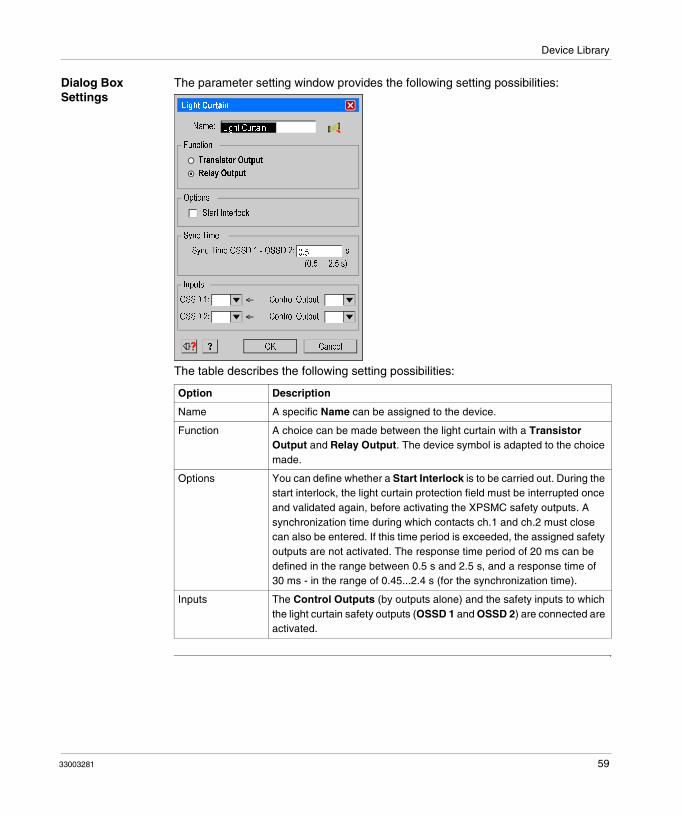
Dialog Box Settings
The parameter setting window provides the following setting possibilities:
The table describes the following setting possibilities:
Option Description
Name A specific Name can be assigned to the device.
Function A choice can be made between the light curtain with a Transistor Output and Relay Output. The device symbol is adapted to the choice made.
Options You can define whether a Start Interlock is to be carried out. During the start interlock, the light curtain protection field must be interrupted once and validated again, before activating the XPSMC safety outputs. A synchronization time during which contacts ch.1 and ch.2 must close can also be entered. If this time period is exceeded, the assigned safety outputs are not activated. The response time period of 20 ms can be defined in the range between 0.5 s and 2.5 s, and a response time of 30 ms - in the range of 0.45...2.4 s (for the synchronization time).
Inputs The Control Outputs (by outputs alone) and the safety inputs to which the light curtain safety outputs (OSSD 1 and OSSD 2) are connected are activated.
Light Curtain
Control Output:
CancelOK
Name:
Transistor Output
Relay Output
Control Output:
?
Function
Inputs
OSSD 1:
OSSD 2:
Start Interlock
Options
Light Curtain
0.5Sync Time OSSD 1 - OSSD 2: s
(0.5 ... 2.5 s)
Sync Time
33003281 59

Device Library
Light Curtain with Muting
Introduction The Light Curtain with Muting folder contains two device symbols:
Light curtain (ESPE = Electro Sensitive Protective Equipment) with transistor outputs or relay outputs, and with muting function.
The muting function can be used to bypass the protection field of a light curtain (ESPE) in order, for example, to bring a part to be worked into and/or leave the hazardous area.
Show a muting example:
The muting function is controlled by four additional sensors belonging to two groups (A and B), and can only be activated when the safety outputs have already been activated (the protection field is then free). If not, the activation of the muting function produces an error message and the safety outputs remain deactivated. Muting operates according to a suitable order of the muting sensors in both directions of transport, and thus inside and outside the hazardous area again.
The muting sensors of groups A and B must be activated during a variable synchronization time tsyn (0.5...3 s with the response time of 20 ms or 0.6...3 s with a response time of 30 ms or to infinity), in order to trigger the muting function. A muting time tM can also be adjusted from 0.5...10 min or to infinity. During this time, the conveyed goods can pass through the activated protection field, without the XPSMC safety outputs switching off the machine. If this time is exceeded, an error message appears and the safety outputs are deactivated.
60 33003281

Device Library
The override button is used to bypass the protection field manually. This is necessary, for example, when the muting function is activated and when conveyed goods have entered and stuck in the light curtain protection field (ESPE). Through this option, the goods can be withdrawn from the machine, in spite of the light curtain (ESPE). To prevent inappropriate use, the override function can only be activated for up to 10 min.
To create the muting signal, sensors with relays output, or mechanical limit switches are suitable for making sure that a distinction is made between individuals and goods. At the same time, all easy defeating must be prevented (stickers or photoelectric sensors for example).
On entering the hazardous area, light signal is recommended to announce the muting status for muting operation; this signal must be connected between terminal H1 and the XPSMC supply voltage (terminal A1). If a fault occurs at the level of this light signal (short-circuit, interruption), the muting function is immediately de-activated and an error message appears. The safety outputs are then deactivated.
Sources of white light with an illumination surface of 1 cm2 and a brightness of at least 200 lm/m are used as a light signal. The current of this light source could vary from 20...350 mA.
The light signal always comes on when the muting signals are generated correctly and announces the bypassing of the light curtain protection function (ESPE):� A new cycle is only initiated with the starting control when no muting signal is
required and when the protection field is free.� During the time a muting signal is produced correctly, no one must be allowed to
enter the hazardous area.
IMPROPER ACCESS TO A PROTECTED AREA
Ensure opening sizes are as small as possible and comply with EN60294.Ensure photo-sensors are clean and free from obstructions.
Failure to follow these instructions can result in death, serious injury, or equipment damage.
DETECTOR INTERFERENCE HAZARD WITH THRU-BEAM SENSORS
Reciprocal mount transmitters and receivers.Mount adjacent receivers at distance greater than minimum separation distance.
Failure to follow these instructions can result in death, serious injury, or equipment damage.
WARNING
WARNING
33003281 61

Device Library
� A guide less means of transport must create the muting signal before it enters the protection field, and may only leave this field when it no longer interrupts the light curtains beams of the protection field.
The muting function meets the requirements of category 4 according to EN 954-1. To ensure the correct monitoring of the muting lamp, a minimum duration of 500 ms for muting is necessary.
Photoelectric muting sensors must operate in dark switching mode, in order to produce the output signal when a light ray is interrupted.
62 33003281

Device Library
Dialog Box Settings
The parameter setting window provides the following setting possibilities:
The table describes the following setting possibilities:
Press the Muting button you get the following Muting Parameters window.
Option Description
Name A specific name can be assigned to this device.
Function A choice can be made between the light curtain with a transistor or relay output. The device symbol is adapted to the choice made.
Options You can define whether a start interlock is to be carried out. During the start interlock, the light curtain protection field must be interrupted once and validated again, before activating the XPSMC safety outputs.
Inputs Both the Control Outputs (by relay outputs only) and the safety inputs to which the light curtain safety relay outputs (OSSD 1 and OSSD 2) are connected are activated.
Light Curtain with Muting
Control Output:
CancelOK
Name:
Transistor Output
Relay Output
Control Output:
?
Function
Inputs
OSSD 1:
OSSD 2:
Start Interlock
Options
Light Curtains
0.5Sync Time OSSD 1 - OSSD 2: s
(0.5 ... 2.5 s, increment 0.1 s)
Muting ...
33003281 63

Device Library
The Muting Parameters window offers the following options:
The following table describes the parameters of the dialog box:
Option Description
Options Muting Time Monitoring:The optional Muting Time indicates the maximum time the muting function is allowed to operate. Exceeding this time with the muting function still activated causes an error message. The Muting Time have the range of 0.5...10 min.Override Time: The Override Time indicates the maximum time during which the relieve time function can be activated. The default value set is 10 min. The Override Time has the range of 0.5...10 minSynchronization Time Monitoring:The optional Sync Time is the time during which the muting sensors of groups A and B must be activated before muting is started. If this time is exceeded, the muting function is not activated. For a response time of 20 ms, the range is 0.5...2.5 s, and for a response time of 30 ms, the range is 0.45...2.4 s for the Sync Time.
Inputs The override input, the 2 groups A and B of muting sensors and the control outputs to which the XPSMC are connected to the light curtain, must be indicated in the Inputs group box. The 2 groups A and B of muting sensors must be necessarily connected to different control outputs.
Muting Parameters
Control Output:
CancelOK
Control Output:
?
Inputs
A 1:
B 1:
Options
Muting Time: min
(0.5 ... 10 min)
Muting Time Monitoring
10Override Time: min
(0.5 ... 10 min)
Sync Time: s
(0.5 ... 3.0 s)
Sync Time Monitoring A1-B1/A2-B2:Control Output:
Override:
A 2:
B 2:
64 33003281

Device Library
Magnetic Switch
Introduction The Monitoring Devices folder contains the Magnetic Switch control device symbol.
The Magnetic Switch consists of an opening contact and a closing contact, which must be actuated within the Synchronization Time, otherwise the Safety Outputs affected are not activated.
Dialog Box Settings
The parameter setting window offers the following settings:
The table describes the following setting possibilities:
Option Description
Name A specific Name can be assigned to this device.
Options You can define whether a Start Interlock is to be carried out. During the Start Interlock, the magnetic switch must be actuated once before the machine is started and then de-activated again to guarantee that the connected contacts are also operating. For the response time of 20 ms, the range is 0.5...2.5 ms, and for the response time of 30 ms, the range is 0.45...2.4 s for the Synchronization Time.
Inputs The control outputs and the safety inputs must be indicated in the Inputs group box.
Magnetic Switch
Control Output:
CancelOK
Name:
Control Output:
?
Inputs
NC:
NO:
Start Interlock
Options
NC
NO
0.5Sync Time: s
(0.5 ... 2.5 s)
Sync Time
Magnetic Switch
33003281 65

Device Library
Two-Hand Control
Introduction The Monitoring Devices folder contains the Two-Hand Control device symbol.
The control panel of the two-hand control consists of two buttons each having an opening contact and a closing contact. These buttons must be actuated within the synchronization time space of 0.5 s, to obtain switching of the safety outputs. If this time is exceeded, the assigned safety outputs are not activated.
To ensure complete short-circuit monitoring, the 2 buttons must be connected to different control outputs. If a button produces an unexpected signal, such as a short-circuit for example, the safety outputs affected are deactivated or are not activated and an error message appears.
Dialog Box Settings
The parameter setting window provides the following setting possibilities:
The table describes the following setting possibilities:
Option Description
Name A specific name can be assigned to this device.
Inputs The control outputs and the safety inputs to which the two-hand control buttons are connected, must be indicated in the Inputs field.
Two Hand Control
Control Output:
OKCancel
Name:
?
Inputs
Button 1:
Button 1:
NO
NC
Control Output:Button 2:
Button 2:
NO
NC
66 33003281

Device Library
Safety Mat
Introduction
The Monitoring Devices folder contains the Safety Mat function symbol.
The switching mat consists of two pairs of metal leads that are short-circuited when the mat is walked on. The XPSMC safety outputs are then immediately deactivated. To be able to detect this short-circuit, the four connection leads must be connected to different safety inputs and control outputs.
Types: see Technical Specifications, Hardware Manual.
Note: 1 of the 3 starting devices: automatic starting, non monitored starting or monitored starting must be assigned to each switching mat function. The corresponding safety output cannot be activated without this assignment.
Note: The control outputs used for this device cannot be used for any other device!
LOSS OF SAFETY INPUT-CROSS CONNECTION DETECTION
In Safety Mat applications, ensure that all four connection leads are connected to different safety inputs and control outputs.
Failure to follow these instructions can result in death, serious injury, or equipment damage.
WARNING
33003281 67

Device Library
Dialog Box Settings
The parameter setting window provides the following setting possibilities:
The table describes the following setting possibilities:
Option Description
Name A specific name can be assigned to this device.
Inputs The control outputs and the safety inputs to which the safety switching mat is connected must be indicated in the Inputs group box.
Safety Mat
Control Output:
OKCancel
Name:
?
Inputs
Input 1:
Control Output:Input 2:
68 33003281

Device Library
Zero Speed Detection
Introduction The Monitoring Devices folder contains the symbol Zero Speed Detection device symbol.
This device detects the zero speed of a motor or a shaft. To enter the motor rotational speed, an encoder wheel and two PNP sensors are required as indicated in figure Functional Diagram, p. 200. These sensors can only be connected to XPSMC safety inputs i1 and i2. If these inputs are already taken, a warning appears automatically.
Points to be Complied
The following points should be complied with for this device:� The sensors must be arranged so that only 1 sensor is activated at any given time
(= HIGH-Signal).� If both sensors are in the LOW state, a cable break error message is indicated
and the corresponding outputs are deactivated.� If both sensors are in the HIGH state after power on of the XPSMC, a notification
is send via Modbus and the corresponding outputs are deactivated. After a zero speed detection and a subsequent motion the notification is reset.
� If zero speed is already detected and both sensors are in HIGH state, a notification is send via Modbus and the corresponding outputs are activated.
� If only 1 sensor produces a dynamic signal after a zero speed, an error message appears after 30 s and the corresponding outputs are deactivated.
� If, after the XPSMC has started, both sensors are in the LOW state, an error message appears.
Note: You cannot use the Zero Speed Detection device simultaneously with the Shift/Chain Break Monitoring device on the XPSMC safety controller, because there are only two counter inputs (i1 and i2) per controller.
Note: The output will be activated if the sensors detect no motion.
33003281 69

Device Library
Sensor States and Behavior
Switch-on Sequence
Operation
* If the state of the sensors is inverse (0/1, 1/0), the behavior is identical.
** If the firmware version is earlier than 2.34 an error message (short circuit between inputs) appears instead of a notification. This error message must be acknowledged with the reset button.
Error Message External error messages must be acknowledged with the reset button.
Notification A notification, sent via Modbus, does not need to be acknowledged. As soon as the sensor states change, it will be acknowledged automatically.
State of Sensor 1 0 0 (*) 1
State of Sensor 2 0 1 (*) 1
Behavior Error Message Zero Speed Notification (**)
Output 0 1 0
State of Sensor 1 0 0 (*) 1
State of Sensor 2 0 1 (*) 1
Behavior Error Message Zero Speed Notification
Output 0 1 1
70 33003281

Device Library
Calculation Both sensors give a frequency depending on the numbers of cogs and the revolution per minute:
or
where
f = Pulse frequency of the sensors in Hertz
n = Rotational speed of the encoder wheel in revolutions per minute
z = Encoder wheel number of cogs
Examples Example 1: Machine with 3000 rpm and an encoder wheel with 26 cogs:
1300 Hz is not authorized, because it is greater than 450 Hz.
Example 2: The same machine (3000 rpm) and an encoder wheel with 8 cogs:
400 Hz is authorized, because it is smaller than 450 Hz.
IMPROPER OPERATON
Do not use the XPSMC in applications where the pulse frequency requirement for detection of cogs on a rotary machine exceeds 450 Hz.
Failure to follow these instructions can result in death, serious injury, or equipment damage.
f Hz[ ] n rpm[ ]60
------------------ z×=
n rpm[ ] f Hz ] 60×[ ]z
-----------------------------=
WARNING
fmax300060
------------ 26× 1300Hz==
fmax300060
------------ 8× 400Hz==
33003281 71

Device Library
Switching Frequency
The frequency limit, below which the zero speed is detected and the safety outputs activated, can be adjusted by the user within a range of 0.05...20 Hz.
Example: A 8-cog encoder wheel is located above a shaft. A zero speed is detected when the speed is less than 10 rpm.
A switching frequency of 1.33 Hz must be indicated to detect a zero speed.
The switching from Motor Operation to Zero Speed (= activation of safety outputs) only occurs when1. 1 safety input contains a HIGH signal and2. the other input contains a LOW signal and3. the frequency on the two inputs is lower than the value entered.
Note: A frequency calculator is included in the properties determination menu. Enter the number of cogs and the zero speed limit in rpm, and the frequency limit to be set is calculated automatically.
fSwitchingfrequency10 rpm[ ]
60--------------------- 8× 1.33Hz= =
72 33003281

Device Library
Dialog Box Settings
The parameter setting window provides the following setting possibilities:
The table describes the following setting possibilities:
Option Description
Name A specific name can be assigned to this device.
Zero Speed Frequency
The frequency limit, below which the zero speed must be detected and the safety outputs activated, must be indicated in this field, as indicated above. For the response time of 20 ms, the range is 0.05...20 Hz, and for the response time of 30 ms, the range is 0.05...16.7 Hz for the Zero Speed Frequency.
Frequency Calculator
A dialogue field opens when you click here.
Inputs (Fixed) i1 and i2
Zero Speed Detection
Sensor 2:
CancelOK
i02
Zero Speed DetectionName:
?
Inputs (fixed)
Sensor 1: i01
Zero Speed Frequency: Hz
(0.05 ... 20 Hz)
Frequency Calculator:
33003281 73

Device Library
The parameter setting window provides the following setting possibilities:
The table describes the following setting possibilities:
Option Description
Rotational Speed Limit
The desired rotational speed limit (in rpm) to detect a zero speed.
Cogs on Encoder Wheel
The number of cogs.
Frequency Limit The frequency limit to be set is calculated automatically; it can be adjusted using the Apply button in the Properties menu.
Frequency Calculator
ApplyCancel
0.10Frequency Limit: Hz
With this setting the actual limit is1.00rpm.
Rotational Speed Limit: rpm
6Cogs on Encoder Wheel:
1
74 33003281

Device Library
Safety inputs i1 and i2 are already automatically indicated in the Inputs field. This device cannot operate with other inputs. If inputs i1 and/or i2 are already used, the following window appears to resolve the conflict:
The table describes the following setting possibilities:
Option Description
Manually or As a user, you assign other safety inputs manually to the function using i1 and/or i2. When OK is clicked, the Properties window of all concerned devices will be opened.
Automatically The software automatically assigns other safety inputs to the function using i1 and/or i2 according to 1 of 3 options:1. shift all inputs
All the safety inputs are shifted as a block. Inputs that are not used and are available may also be shifted.For example, i1 becomes i3, i2 becomes i4 and i4 becomes i6.
2. move up inputsAll the safety inputs are shifted as a block. Inputs that are not used and are available may also be shifted, and spaces thus filled.For example, i1 becomes i3, i2 becomes i4 and i4 becomes i5.
3. replace only concerned inputsOnly the inputs that are used (i1 and/or i2) are shifted to the next free safety inputs. This is the standard option.
Input Selection
OKCancel
manually or
automatically
Do you want to rearrange the inputs
This function needs to use inputs 1 and 2 which are already used elsewhere (See the yellow warning mark(s)).
You need to rearrange your input selection to free these inputs.
shift all inputs (incl. unused)
replace only concerned inputs
Automatic Mode:
move up inputs (use unused)
33003281 75

Device Library
Injection Molding Machine
Introduction
The Specific Functions folder contains the Injection Molding Machine device symbol for monitoring an injection molding machine with a protection door, as indicated in figure Wiring Diagram, p. 206.
The 3 limit switches Ch.1, Ch.2 and Valve must then be connected to various control outputs and safety inputs, to ensure complete short-circuit monitoring. The injection molding machine is activated according to the switching states of limit switches Ch.1, Ch.2 and Valve, in accordance with the function diagram in figure Functional Diagram, p. 204. A Start Interlock is, in this case, mandatory, i.e. the protection door must be opened once and then closed again, to make starting possible.
Note: 1 of the 3 starting devices: automatic starting, non monitored starting or monitored starting must be assigned to each injection molding machine device. The corresponding safety output cannot be activated without this assignment.
76 33003281

Device Library
Dialog Box Settings
The parameter setting window provides the following setting possibilities:
The table describes the following setting possibilities:
Option Description
Name A specific name can be assigned to this device.
Sync Time A synchronization time, during which contacts ch.1 and ch.2 must close, must be entered in this field. If this time is exceeded, the assigned safety outputs are not activated. For the response time of 20 ms, the range is 0.5...2.5 s, and for the response time of 30 ms, the range is 0.45...2.4 s for the Synchronization Time.
Inputs The safety inputs and control outputs used must be indicated in this field.
Injection Molding Machine
Control Output:
CancelOK
Injection Molding MachineName:
?
Inputs
Ch.1:
Control Output:Ch.2:
Sync Time: s
(0.5 ... 2.5 s)
Control Output:Valve:
33003281 77

Device Library
Hydraulic Press Valve Monitoring
Introduction The Specific Functions folder contains the Hydraulic Press Valve Monitoring device symbol for monitoring a hydraulic press valve, as indicated in figure Wiring Diagram, p. 208.
Using this device, a hydraulic press with safety valves with three position switches or with PNP sensors Valve C to Valve C+O can be connected to the XPSMC, as shown in the figure Wiring Diagram, p. 208. The press control delivers the press opening and closing signals. Each time the leading edge of the two press control signals, OPEN PRESS and CLOSE PRESS goes positive, a configurable internal time window is generated, during which the XPSMC waits for a response from the appropriate valve position switch (Valve C and Valve C+O for press closing, Valve O for press opening). If this time window is exceeded, the corresponding safety outputs are deactivated.
If signals Valve C to Valve C+O appear in an order other than the one shown in figure Functional Diagram, p. 207, the affected safety outputs of this function are then deactivated and an error message appears.
This function thus delivers the CLOSING AUTHORIZATION signal to a safety output, if the CLOSE PRESS signal is active and if Valve C and Valve C+O are closed correctly in the time window.
The OPENING AUTHORIZATION signal will also be activated on a safety output, if the OPEN PRESS signal is active and if Valve O is closed correctly in the time window.
When this device is selected, it is first necessary to assign the OPENING AUTHORIZATION function to a safety output and the CLOSING AUTHORIZATION function to another safety output.
This takes place in the window which appears automatically:
Output Selection
CancelOK
Enable CLOSING
Enable OPENING
The selected output o6 shall be used for:
This function has two outputs: one for the opening and one for the closing of the press.
Please select the other output:
Enable OPENING:
o6:
78 33003281
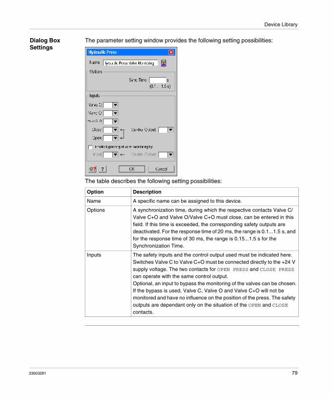
Device Library
Dialog Box Settings
The parameter setting window provides the following setting possibilities:
The table describes the following setting possibilities:
Option Description
Name A specific name can be assigned to this device.
Options A synchronization time, during which the respective contacts Valve C/Valve C+O and Valve O/Valve C+O must close, can be entered in this field. If this time is exceeded, the corresponding safety outputs are deactivated. For the response time of 20 ms, the range is 0.1...1.5 s, and for the response time of 30 ms, the range is 0.15...1.5 s for the Synchronization Time.
Inputs The safety inputs and the control output used must be indicated here. Switches Valve C to Valve C+O must be connected directly to the +24 V supply voltage. The two contacts for OPEN PRESS and CLOSE PRESS can operate with the same control output.Optional, an input to bypass the monitoring of the valves can be chosen.If the bypass is used, Valve C, Valve O and Valve C+O will not be monitored and have no influence on the position of the press. The safety outputs are dependant only on the situation of the OPEN and CLOSE contacts.
Hydraulic Press
CancelOK
Hydraulic Press Valve MonitoringName:
?
Inputs
Valve C:
Valve O:
Control Output:Close:
Open:
Sync Time: s
(0.1 ... 1.5 s)
Enable bypassing of valve monitoring by:
Options
Valve C+O:
Control Output:Input:
33003281 79

Device Library
Hydraulic Press 2
Introduction The Specific Functions folder contains the Hydraulic Press 2 Functions device symbol for a hydraulic press with valve monitoring and optional overtravel monitoring, as indicated on the Wiring Diagram, p. 208.
This device provides an internal mode selector switch function for the operation modes OFF / INCHING / SINGLE STROKE / AUTOMATIC of the hydraulic press. The use of the overtravel monitoring functionality is optional. The press control delivers the press opening and closing signal; the use of these inputs is mandatory when Automatic mode is selected. The use of the input for the Open command is also mandatory when mode Inching is selected. In Inching mode, valve monitoring is not active.
When you drag-and-drop the Hydraulic Press 2 device onto an output, the following window appears. Here you can select the output you need and enable either the opening or the closing movement of the machine.
Output Selection
CancelOK
Enable CLOSING
Enable OPENING
The selected output o5 shall be used for:
This function has two outputs: one for the opening and one for the closing of the press.
Please select the other output:
Enable OPENING:
o5:
80 33003281

Device Library
The following image shows the output selection options:
Hydraulic Press 2
CancelOK
Name:
?
Inputs
Close:
Open:
Control Output
2 - Single Stroke:
1 - Inching:
3 - Automatic:
Sync Time: s
(0.1 ... 1.5 s)
Mode Selector Switch
0 - Off
* contact position ofdeactivated valve
Hydraulic Press 2
Valve O:
Valve C:
on
on *
*
Valve C + O: off *
Use Open/Close Signals from PLC
NWK:
Kx:
Control Output
Use Overtravel Monitoring used
OTS:
UT:
Control Output
Control Output
33003281 81

Device Library
Dialog Box Settings
The following table describes dialog settings of the Hydraulic Press 2:
Option Description
Name A specific name can be assigned to this device.
Options Here you can enter synchronization time in which respective contacts Valve C / Valve C+O and Valve O / Valve C+O must be moved (opened or closed). If the time is exceeded, corresponding Safety Outputs are deactivated. For the response time of 20 ms, the range is 0.1...1.5 s; for the response time, the range is 0.15...1.5 s for the Synchronization Time.
Inputs The safety inputs and the control output used must be indicated here. Switches Valve C to Valve C+O must be connected directly to +24 V supply voltage.NWK and Kx are an own control output. The close and opening contact use also only 1 control output.
82 33003281

Device Library
Mode Selector Switch
The following operation modes are available:� Mode Off
The press is deactivated and all safety outputs connected to the press are turned off.
� Mode InchingPosition switches OTS and UN as well as the switches of the valves PSV1 and PSV2 will not be monitored, and have no influence on the movement of the press. The safety outputs are dependant only on the situation of the Safety Means and Start.
� Mode Single StrokeWith each releasing of the start device, for instance Two-Hand Control, one stroke of the press is implemented. The safety stopping at the top dead centre is realized by the limit switches OTS and UN. The automatic upstroke is controlled by the closing of the limit switch UN. In addition, with selected valve monitoring, the synchronous time of the two halves of the press safety valve (PSV) are monitored with the switches PSV1 and PSV2 when switching on and off.
� Mode ContinuousThe functions of monitoring correspond in theory to those of the mode Single Stroke, however the press does not stop after one cycle. The continued operation starts with the input Safety Means and Start, and the press runs until the Safety Means and Start input is released or the Continuous Off switch is switched off. Dynamic monitoring of the valve and the monitoring of overtravel will only be performed one time in the continuous cycle.
� Mode Continuous AutomaticThe function of monitoring corresponds to those of the mode Single Stroke, however the press does not stop after one cycle. Continued operation starts with the input Safety Means and Start (after the start, the device can be deactivated), and the press runs until the Continuous Off switch is actuated or the Safety Means for Continuous Automatic input is switched off. Dynamic monitoring of the valve and monitoring of overtravel will only be performed one time in the continuous cycle.
Note: In the following situations, reoperate all safety means:� The E-Stop has been pressed.� The operation mode has been changed.� The opening has been finished in single stroke or inching.� Safety means for presses that are not to be operated each stroke should be
dragged and dropped onto the press output and not on the press itself.
Option Description
33003281 83

Device Library
Eccentric Press
Introduction The Specific Functions folder contains the Eccentric Press symbol to control the safety stopping of an eccentric press at top dead center (OTS) with over-travel monitoring and optional valve monitoring.
The press must be operated with a two-hand control device. The XPSMC safety outputs are activated as long as the start signal is active at the beginning of the cycle and the position switches OTS, UN,PSV1, and PSV2 deliver the correct signals throughout the cycle. To enable short-circuit detection, the position switches must be connected to different safety inputs and control outputs.
The function detailed operation differs according to the selected operating method.
Position switches OTS and UN detect the press movement and in particular safety stopping at the top of the dead center OTS.
The control cams are shown on the following functional diagram:
Position switches PSV1 and PSV2 monitor the status of the press safety valve. For the response time of 20 ms, the range is 0.1...1.5 s, and for the response time of 30 ms, the range is 0.15...1.5 s for the Synchronization Time. If this time is exceeded, an error message appears, and the corresponding safety outputs are deactivated until the Reset input is activated.
OTS
UN
Hazardousmotion
Braking angle
Cam
OTS
CamUN
approx. 150°
approx. 300°
approx. 10°
OTS
UN
Positionswitch
Position
switch
Maintain=Automatic opening
Acceptableovertravel
0° = Top dead center OTS
Representation at OTS
Normallyopen"NO"
Normally
closed"NC"
84 33003281

Device Library
To delete an overtravel error or an error at the UN or OTS position switches, the Reset input must be actuated. The errors on the press safety valves, the UN or OTS position switches, and overtravel will not be cleared by switching off the controller.
If one of the safety inputs delivers an incorrect signal, an error message appears, and the corresponding safety outputs are deactivated.
33003281 85

Device Library
Dialog Box Settings
The parameter settings window provides the following setting possibilities:
Description of the settings window:
Setting Description
Name A specific Name can be assigned to the device.
Options The valve monitoring can be activated, and the Synchronization Time for the switch ON and Off of the press safety valves PSV1 and PSV2 can be adjusted. For the response time of 20 ms, the range is 0.1...1.5 s, and for the response time of 30 ms, the range is 0.15...1.5 s for the Synchronization Time.
Inputs Relation between inputs and control outputs can be selected.
Eccentric Press
OKCancel
Eccentric PressName:
?
Inputs
OTS:
UN:
Control Output:
PSV2:
ContinousOff:
Sync Time PSV1-PSV2 (s): (0.1 ... 1.5 s)
Valve Monitoring
Options
PSV1:
Control Output:
Control Output:
Control Output:
Reset:
Inching:
Off:
Continuous Autim.:
Single Stroke:
Mode Selector Switch:
86 33003281

Device Library
Mode Selector Switch The following operation modes are available:� Mode Off
The press is deactivated and all safety outputs connected to the press are turned off.
� Mode InchingPosition switches OTS and UN as well as the switches of the valves PSV1 and PSV2 will not be monitored, and have no influence on the movement of the press. The safety outputs are dependant only on the situation of the Safety Means and Start.
� Mode Single StrokeWith each releasing of the start device, for instance Two-Hand Control, one stroke of the press is implemented. The safety stopping at the top dead centre is realized by the limit switches OTS and UN. The automatic upstroke is controlled by the closing of the limit switch UN. In addition, with selected valve monitoring, the synchronous time of the two halves of the press safety valve (PSV) are monitored with the switches PSV1 and PSV2 when switching on and off.
� Mode ContinuousThe functions of monitoring correspond in theory to those of the mode Single Stroke, however the press does not stop after one cycle. The continued operation starts with the input Safety Means and Start, and the press runs until the Safety Means and Start input is released or the Continuous Off switch is switched off. Dynamic monitoring of the valve and the monitoring of overtravel will only be performed one time in the continuous cycle.
� Mode Continuous AutomaticThe function of monitoring corresponds to those of the mode Single Stroke, however the press does not stop after one cycle. Continued operation starts with the input Safety Means and Start (after the start, the device can be deactivated), and the press runs until the Continuous Off switch is actuated or the Safety Means for Continuous Automatic input is switched off. Dynamic monitoring of the valve and monitoring of overtravel will only be performed one time in the continuous cycle.
Setting Description
33003281 87

Device Library
Eccentric Press 2
Introduction The Specific Functions folder contains the Eccentric Press 2 device symbol to control the safety stopping of an eccentric press at top dead center (OTS) with over-travel monitoring and optional valve monitoring. The valve monitoring shown in the Wiring Diagram, p. 218 is optional. The press must be operated with the minimum of 1 device, such as Light Curtains without Muting, Safety Guard, Magnetic Switch, Two-Hand Control, Foot Switch, and Selector Switch.
The XPSMC safety outputs are activated as described for the different operation modes and the position switches OTS, UN, PSV1 and PSV2 deliver correct signals throughout the cycle. To enable short-circuit detection, the position switches must be connected to different safety inputs and control outputs. The function-specific operations differ according to the selected operation mode. Position switches OTS and UN detect the press movement and ensure safety stopping at the top dead center OTS.
The control cams are shown on the following functional diagram:
OTS
UN
Hazardous
motionBraking angle
Cam
OTS
CamUN
approx. 150°
approx. 300°
approx. 10°
OTS
UN
Positionswitch
Position
switch
Maintain=Automatic opening
Acceptable
overtravel
0° = Top dead center OTS
Representation at OTS
Normally
open"NO"
Normallyclosed
"NC"
88 33003281

Device Library
Two more switches PSV1 and PSV2 monitor the status of the press safety valve. For the response time of 20 ms, the range is 0.1...1.5 s, and for the response time of 30 ms, the range is 0.15...1.5 s for the Synchronization Time. If this time is exceeded, an error message appears, and corresponding safety outputs are deactivated until the reset input is activated.
To delete an overtravel error or an error at the UN or OTS position switches, the reset input has to be actuated. The errors on the press safety valves, the UN or OTS position switches and overtravel will not be cleared by switching off the controller.
If one of the safety inputs delivers an incorrect signal, an error message appears and the corresponding safety outputs are deactivated.
33003281 89
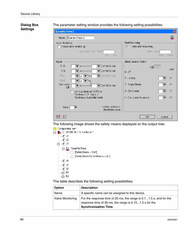
Device Library
Dialog Box Settings
The parameter setting window provides the following setting possibilities:
The following image shows the safety means displayed on the output tree:
The table describes the following setting possibilities:
Option Description
Name A specific name can be assigned to this device.
Valve Monitoring For the response time of 20 ms, the range is 0.1...1.5 s, and for the response time of 30 ms, the range is 0.15...1.5 s for the Synchronization Time.
Eccentric Press 2
CancelOK
Name:
?
Inputs
OTS:
UN:
Control Output:
PSV2:
ContinuousOff:
PSV1:
Control Output:
Control Output:
Control Output:
Reset:
2 - Single Stroke:
1 - Inching:
4 - Continuous Automatic:
3 - Continuous:
Sync Time PSV1-PSV2: s
(0.1 .. 1.5 s)
Enable Valve Monitoring
Dead Time: s
(0.05 .. 0.50 s)
Shaft Monitoring
Enable shaft Monitoring
Mode Selector Switch
on
on *
*
0 - Off
* contact position ofdeactivated valve
Eccentric Press 2
Valve Monitoring
used
continue stroke until OTS on’Continuous Off’ signal in ’Continuous Automatic’ mode
’Eccentric Press’
i Configuration: ’wer’
i C1 (XPSMC16 ZP): ’Controller1’i16
R1
R2
o1
o2
o3
o4
o6
[Safety Means + Start]
[Safety Means for Continuous Auto.]
o5
90 33003281

Device Library
Shaft Monitoring For the response time of 20 ms, the range is 0.05...0.50 s, and for the response time of 30 ms, the range is 0.06...0.48 s for the Synchronization Time.
Inputs The used inputs and the control output must be indicated in this field (see the Wiring Diagram, p. 206. The stopping functionality of the Continuous Off signal can be defined. The Reset Switch and Mode Selector Switch must be connected directly to the +24 V supply voltage.
Mode Selector Switch
The following operation modes are available:� Mode Off
The press is deactivated and all safety outputs connected to the press are turned off.
� Mode InchingPosition switches OTS and UN as well as the switches of the valves PSV1 and PSV2 will not be monitored, and have no influence on the movement of the press. The safety outputs are dependant only on the situation of the Safety Means and Start.
� Mode Single StrokeWith each releasing of the start device, for instance Two-Hand Control, one stroke of the press is implemented. The safety stopping at the top dead centre is realized by the limit switches OTS and UN. The automatic upstroke is controlled by the closing of the limit switch UN. In addition, with selected valve monitoring, the synchronous time of the two halves of the press safety valve (PSV) are monitored with the switches PSV1 and PSV2 when switching on and off.
� Mode ContinuousThe functions of monitoring correspond in theory to those of the mode Single Stroke, however the press does not stop after one cycle. The continued operation starts with the input Safety Means and Start, and the press runs until the Safety Means and Start input is released or the Continuous Off switch is switched off. Dynamic monitoring of the valve and the monitoring of overtravel will only be performed one time in the continuous cycle.
� Mode Continuous AutomaticThe function of monitoring corresponds to those of the mode Single Stroke, however the press does not stop after one cycle. Continued operation starts with the input Safety Means and Start (after the start, the device can be deactivated), and the press runs until the Continuous Off switch is actuated or the Safety Means for Continuous Automatic input is switched off. Dynamic monitoring of the valve and monitoring of overtravel will only be performed one time in the continuous cycle.
Option Description
33003281 91

Device Library
Depending on whether Enable Shaft Monitoring is selected or not, the corresponding device will or will not appear in the Configuration window immediately under Eccentric Press.
Without shaft monitoring
With shaft monitoring
When devices have been moved to the safety means, the safety means to be started in the Continuous Automatic mode appear underneath the corresponding small circles, as shown in the example below.
’Eccentric Press’
i Configuration:
i C1 (XPSMC32 ZP): ’Controller1’i32
R1
R2
o1
o2
o3
o4
o5
o6
[Safety Means + Start]
[Safety Means for Continuous Auto.]
’Eccentric Press’
i Configuration:
i C1 (XPSMC32 ZP): ’Controller1’i32
R1
R2
o1
o2
o3
o4
o5
o6
Shaft/Chain Break Monitoring
[Safety Means + Start]
[Safety Means for Continuous Auto.]
92 33003281

Device Library
Two-hand control and a light curtain
Note: The Selector Switch device can be used to provide the signals for Safety Means and Start and/or Safety Means and Continuous Automatic to the press device. The Selector Switch devices permit a great deal of flexibility regarding various safety means for the different operation modes (see Selector Switch, p. 109).Safety means for presses that are not to be operated each stroke should be dragged and dropped onto the press output and not on the press itself.
’Eccentric Press’
i Configuration:
i C1 (XPSMC32 ZP): ’Controller1’i32
R1
R2
o1
o2
o3
o4
o5
o6
Shaft/Chain Break Monitoring
[Safety Means + Start]
[Safety Means for Continuous Auto.]
’Light Curtain’
’Two Hand Control’
33003281 93

Device Library
Shaft/Chain Break Monitoring
Introduction The Specific Functions folder contains the Shaft/Chain Break Monitoring icon. The device is used to monitor the movement of a cam switch mechanism of an eccentric press, as shown in the Shaft/Chain-Break Monitoring, p. 229. This device is directly linked to the OTS and UN position switches by a cogwheel sensor and can only be connected either to input i1 or i2. You can drag and drop the device from the library onto any output of the controller. For theEccentric Press 2 device, you can only enable the Shaft Monitoring device inside the Properties window.
Dialog Box Settings
The parameter setting window provides the following possibilities:
The table describes the following setting possibilities:
Option Description
Name A specific name can be assigned to this device.
Options For the response time of 20 ms, the range is 0.02...0.10 s, and for the response time of 30 ms, the range is 0.03...0.9 s for the Pulse cycle.
Inputs Only i01 or i02 are selectable.
Note: You can only use 2 different Shaft/Chain Break Monitoring devices in 1 XPSMC, because there are only 2 counter inputs (i1 and i2) available, see also Zero Speed Detection, p. 69.
Shaft/Chain Break Monitoring
CancelOK
Name:
IPulse Cycle: s
(0.02 .. 0.10 s)
Sensor:
? ?
Options
Shaft/Chain Break Monitoring
Input
Only input i01 or i02 can be used to connect the sensor.
Pulse Cycle Calculator:
94 33003281

Device Library
Seat Valve Monitoring
Introduction The Specific Functions folder contains the device symbol for monitoring of a seat valve as shown in figure Wiring Diagram, p. 232.
The device senses the start signal for operating the valve with the first input and the answer signal of the concerned valve contact with the second input.
Dialog Box Settings
The parameter setting window provides the following setting possibilities:
The table describes the following setting possibilities:
Option Description
Name A specific name can be assigned to this device.
Options The function of the valve contact can be selected as either NO or NC. For the response time of 20 ms, the range is 0.1...3.0 s, and for the response time of 30 ms, the range is 0.15...3.0 s for the Synchronization Time.
Inputs After the start signal is given and the valve contact is not operating, the output of the device is immediately activated and remains activated until the synchronisation time is exceeded. The output only remains activated if the valve contact is operating during the synchronisation time. After this, the valve contact may open and close without disrupting the output as long as the start signal is maintained. If the start command disappears, the output will always be deactivated.
Seat Valve Monitoring
Seat Valve MonitoringName:
NO
NC
Control Output:
CancelOK?
Inputs
Start:
Control Output:Valve:
Sync Time: s
(0.1 ... 3.0 s)
Sync Time Monitoring Start - Valve:
Valve Contact:
Options
33003281 95

Device Library
96 33003281

Device Library
4.3 EDM Devices
EDM Device (External Device Monitoring)
Introduction The EDM Device folder contains the device symbol for monitoring a feedback loop. This device is used to monitor external devices such as subsequent contactors or relays.
If, for example, external contactors K1 / K2 are activated, the EDM input to which opening contacts K1 and K2 are assigned must then be opened, by the end of the adjustable synchronization time at the latest. If this is not the case, an error message appears and the safety outputs concerning K1 and K2 are deactivated.
Before activating the safety output, ensure that the EDM input is activated. If it is not, an error message appears, and the safety output gets deactivated.
Dialog Box Settings
The parameter setting window provides the following setting possibilities:
The table describes the following setting possibilities:
Option Description
Name A specific name can be assigned to this device.
Options A synchronization time, during which the return circuit must open, can be entered in this field. If this time is exceeded, the corresponding safety output is deactivated. For the response time of 20 ms, the range is 0.1...0.5 s, and or the response time of 30 ms, the range is 0.15...0.5 s for the Synchronization Time. If the Synchronization Time is not activated, only check whether the EDM input is closed immediately before activating the safety outputs.
Inputs The safety input and the control output must be indicated in this field.
EDM
Name:
Control Output:
OKCancel?
Inputs
Input:
EDM Time (s):
(0.15 .. 0.50 s)
Options
EDM Time Monitoring:
33003281 97

Device Library
4.4 Start Device
Start Device
Introduction The Start Devices folder contains 3 device symbols for
� Automatic Start,� Non-Monitored Start,� Monitored Start.
The functional diagram for these devices is shown, as an example, in figure Functional Diagram, p. 174.
Dialog Box Settings
The parameter setting window provides the following setting possibilities:
The table describes the following setting possibilities:
Option Description
Name A specific name can be assigned to this device.
Start
Name:
Automatic Start
Non monitored Start
Control Output:
OKCancel?
Input
Start:
Function
positiv
negativ
Trigger Edge:
Options
Monitored Start
98 33003281

Device Library
Function You can then select one of the starting devices again in this field. The device symbol in the configuration tree is adapted automatically.The following options are available:� Automatic Start
The safety outputs are activated as soon as all the starting conditions are fulfilled. A start button is not necessary.
� Non monitored StartThe safety outputs are activated as soon as all the starting conditions are fulfilled and starting is initiated by the start button being pressed. The Start button must not re-activated to launch the Start device, and the non monitored start then operates in the same way as the automatic start.
� Monitored StartIn this case, the safety outputs are only activated when all the starting conditions are fulfilled and starting is initiated when the start button is pressed (automatic start on a positive trigger edge) or when the start button is pressed and released (automatic start on a negative trigger edge). It is possible to define whether starting should take place on the positive-going edge or negative-going edge of the starting signal. Unlike non monitored starting, the safety output cannot be activated when the start button is actuated by an XPSMC Power-Up or when the start button is maintains status 1 for some time after the operation. This will cause an error message.
Options During monitored starting, a selection can be made in this field between automatic start on a positive trigger edge (= starting when the start button is pressed) or automatic start on a negative trigger edge(= starting when the start button is released).
Inputs The safety input and the control output must be indicated here.
Option Description
33003281 99

Device Library
4.5 Enabling Devices
Two-Channel or Three-Channel Enabling Device
Introduction The Enabling Devices folder contains 2 device symbols for the enabling switch. This device can be used alone on a safety output, with a safety guard or together with a safety guard on the OR device.
With an enabling switch, a safety guard can be bypassed and a hazardous movement can consequently be started, even with a protection door open, during the fitting out of a machine for example. The enabling switch does not activate the dangerous movement but gives a validation for the dangerous movement to be actuated.
This function works with a two or three channel enabling switch (Wiring Diagram, p. 234 or figure Wiring Diagram, p. 236). Category 4 is only achieved when using the 3 position enabling switch. For the types of enabling switches that can be used, see the Technical Data chapter of the Hardware instruction manual.
To produce the confirmation signal, the enabling switch must first be set to position 0 and then to position 1. The authorization is thus activated, as are the XPSMC safety outputs. If the enabling switch reaches position 2, the safety outputs are again deactivated. When the enabling switch is set back to position 0, no further enabling is authorized, even if the switch is returned to position 1.
Note: The enabling device can be dragged and dropped together with a safety guard onto the OR device. An external switch (preferably a key switch) should be used to enable the input of the enabling device.
100 33003281

Device Library
Dialog Box Settings
The parameter setting window provides the following setting possibilities:
The table describes the following setting possibilities:
Option Description
Name A specific name can be assigned to this device.
Function You can select one of the enabling switches in this field. The device symbol in the configuration tree is adapted automatically. The switching diagram needed for the contact switch is also schematically illustrated here.
Options Here a max. enable time can be given. If the enabling switch is active longer than the enable time, the corresponding safety outputs will be deactivated and a fault message will be given. The time is adjustable from 0.5...10 min.
Inputs The safety inputs and control outputs used must be indicated in this field. To ensure reliable short-circuit detection, all the contacts must be set into service on different control outputs.
Enabling Device
Control Output:
CancelOK
Enabling DeviceName:
two channels
Control Output:
?
Function
Inputs
Ch 1:
Ch 2:
Enable Time: min
(0.5 ... 10 min)
Enable Time Monitoring:
Three channels
Options
Control Output:Ch 3:
NO
NC
NO
33003281 101

Device Library
102 33003281
Device Library
4.6 Miscellaneous Devices
At a Glance
Overview This section contains the description of the Miscellaneous Devices folder, which contains all the logic devices.
What's in this Section?
This section contains the following topics:
Topic Page
Timer 104
OR Device 106
Foot Switch Control Device 107
Selector Switch 109
Closed Tool Device 112
33003281 103

Device Library
Timer
Introduction The Miscellaneous Devices folder contains the Timer device symbol. Figure Functional Diagram, p. 226 indicates the corresponding functional diagrams.
This device enables the safety output(s) with the timer function.
Dialog Box Settings
The parameter setting window provides the following setting possibilities:
The table describes the following setting possibilities:
Option Description
Name A specific name can be assigned to this device.
Timer
Control Output:
CancelOK
TimerName:
switch ON delay
?
Function
Input
Input:
Time: s
(0.1 ... 300 s)
switch OFF delay
switch ON pulse
switch OFF pulse
Input:
104 33003281

Device Library
Function You can select one of the four operating modes: 1. Switch ON delay
If the safety input changes its status from 0 to 1 and stays at 1, the adjustable time delay starts, and the time delay has reached its setpoint, the safety output is set to 1. If the control output is set to 0, the safety output is simultaneously set to 0. If the safety input status changes to 0, and the time delay has not expired, the safety output remains at 0.
2. Switch OFF delayIf the safety input changes its status from 0 to 1, the safety output is immediately set to 1. If the safety input changes its status from 1 to 0 and stays at 0, the adjustable time delay starts, and the time delay has reached its setpoint, then the safety output is set to 0. If the safety input status changes to 1, and the time delay has not reached its setpoint, the safety output remains at 1.
3. Switch ON pulseIf the safety input changes its status from 0 to 1 and stays at 1, the adjustable time delay starts, and the safety output is simultaneously set to 1. The safety output is set to 0, if the time delay has reached its setpoint, or the safety input changes to 0.
4. Switch OFF pulseIf the safety input changes its status from 1 to 0, then the adjustable time delay starts, and the safety output is set to 1. The safety output is set to 0, if the time delay has reached its setpoint.
The function is presented by an explanatory schematic diagram.
Time For a response time of 20 ms the range is 0.1 to 300 s and for a response time of 30 ms the range is 0.15...300 s.
Inputs The safety input and the control output used for the control signal must be indicated here.
Option Description
33003281 105

Device Library
OR Device
Introduction The Miscellaneous Devices folder contains the symbol of the OR Device.
The result of an OR connection between several devices is validation of an output.
There are no properties available for this device.
The OR component cannot be used with an E-Stop device.
106 33003281

Device Library
Foot Switch Control Device
Introduction The Miscellaneous Devices folder contains the Foot Switch Control device symbol. The device monitors a NO and NC contact from 1 control output.
Dialog Box Settings
The parameter setting window provides the following setting possibilities:
The table describes the following setting possibilities:
Option Description
Name A specific Name can be assigned to this device.
Options � Start Interlock: Foot switch must be released before starting the foot switch function.
� Sync Time Monitoring: for the response time of 20 ms, the range is 0.5...2.5 s, and for the response time of 30 ms, the range is 0.45...2.4 s for the Synchronization Time, required for the 2 inputs, NO and NC.
Inputs The Inputs must be supplied from a control output.
HAZARDOUS APPLICATIONS
Do not use foot switches on machines without point-of-operation protection.
Failure to follow these instructions will result in death or serious injury.
Foot Switch Control
CancelOK
Name:
?
Inputs
Control Output:Contact NO:
Contact NC:
Sync Time: s
(0.5 ... 2.5 s)
Start Interlock
Options
Foot Switch Control
Sync Time Monitoring:
NO
NC
DANGER
33003281 107

Device Library
Note: The use of the Foot Switch requires additional safety measures! The Foot switch does not provide technical safety for a press control. Example: In order to control the continuous mode of a press with the Foot Switch, additional safety means are necessary (e.g., Safety Guard, Light Curtain).
108 33003281

Device Library
Selector Switch
Introduction The Miscellaneous Devices folder contains the Selector Switch device symbol.
You can drag the selector switch device symbol to either the Eccentric Press 2, the Hydraulic Press 2, or directly to an output.
The selector switch device helps you to select the devices to be used as safety means and start means. When you drag and drop the selector switch symbol onto an output or a press, no dilaog box will appear, because you should first drag and drop all relevant devices onto the switch and configure them, before you define your selection.
The following is a list of devices that can be dragged and dropped onto the Selector Switch device (their number is limited by the number of inputs of the controller).
For the Hydraulic Press 2 and Eccentric Press 2 (Safety Means + Start / Safety Means for Continuous Automatic):
� Safety Guards� Light Curtains without Muting� Magnetic Switches� Two-Hand Control� Foot Switch� Enabling Device� Closed Tool device
For an output:
� Safety Guards� Light Curtains� Magnetic Switches� Two-Hand Control� Foot Switch Control� Safety Mat� Zero Speed Detection� Hydraulic Press� Eccentric Press� Shaft / Chain Break Monitoring� Seat Valve Monitoring� Start devices� Enabling devices� Timer
33003281 109

Device Library
The following image shows the selector switch on a safety means and start of the Eccentric Press 2 with three related devices:
’Foot Switch Control’
’Eccentric Press’
’Magnetic Switch’
’Two Hand Control’
i Configuration:
i C1 (XPSMC32 ZC): ’Controller1’i32
’Selector Switch’
R1
R2
o1
o2
o3
o4
o5
o6
[Safety Means + Start]
[Safety Means for Continuous Automatic]
110 33003281

Device Library
Dialog Box Settings
The following image shows the selector switch with related devices. Here you can allocate the devices to the relevant input.
The parameter setting window provides the following setting possibilities:
The table describes the following setting possibilities:
For the safety means and start it is active in� Position 1: Two-Hand Control � Position 2: Magnetic Switch � Position 3: Foot Switch Control and Magnetic Switch
Option Description
Name A specific name can be assigned to this device.
Device Declaration Selector Switch position: Select the relevant input to the selector switch position.
Selector Switch
CancelOK
Name:
?
Device Declaration
Input: i01
Selector Switch Position: 1
Selector Switch
i02
2
i03
3 4 5 6
used:
’Two Hand Control’:
’Foot Switch Control’:
’Magnetic Switch’:
33003281 111

Device Library
Closed Tool Device
Introduction The Miscellaneous Devices folder contains the Closed Tool symbol. You can use this device with a Selector Switch and an additional start device (e.g., Foot Switch Control) on Hydraulic Press 2 or Eccentric Press 2. You can also move it directly to the safety means for continuous automatic operation of the Eccentric Press 2.
When you configure the Closed Tool device directly to the Safety Means for continuous automatic operation of the Eccentric Press 2, you also need an external key switch to enable the continuous automatic operation as well as a signal lamp.
112 33003281

Device Library
4.7 State of Outputs
Applying Output States to Other Safety Outputs
Introduction The Output states folder contains the symbol of the safety outputs for each controller.
By moving the output X symbol on the output Y in the Configuration window, the safety output Y will have the same behavior as the safety output X. Other components can be assigned to the output Y.
The same result will be achieved by moving the output X symbol with the left mouse button onto the output Y.
Example
In this example, safety output o1 is associated with Non monitored Start, Safety Guard and two channel Emergency Stop. Safety output o2 represents the 2nd channel of this safety function and will behave exactly like o1.
No adjustment is provided for in this function. Modifications can only be performed in the original safety function (in this case, safety output o1); they are then taken into account automatically in the corresponding safety output.
i
C1: ’Controller1’i16
Configuration:
i
o1
’Emergency Stop’
’Safety Guard’
o1 (C1)
o2
’Non monitored Start’
33003281 113

Device Library
114 33003281
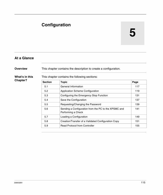
33003281
5
ConfigurationAt a Glance
Overview This chapter contains the description to create a configuration.
What's in this Chapter?
This chapter contains the following sections:
Section Topic Page
5.1 General Information 117
5.2 Application Scheme Configuration 119
5.3 Configuring the Emergency Stop Function 131
5.4 Save the Configuration 137
5.5 Requesting/Changing the Password 139
5.6 Sending a Configuration from the PC to the XPSMC and Performing a Check
141
5.7 Loading a Configuration 149
5.8 Creation/Transfer of a Validated Configuration Copy 151
5.9 Read Protocol from Controller 155
115

Configuration
116 33003281

Configuration
5.1 General Information
Generals
Introduction
By way of example, the creation of a configuration is explained by means of the following application:
The entry of personnel into the hazardous zone of the robot arm is prevented by the guard/protection door with 2 limit switches. For adjustment and maintenance purposes, the robot arm may also be controlled when the door is open by using an enabling switch. The choice of using the guard or enabling switch for personnel safety is done by an external selector switch mounted near the guard. The safety of any personnel inside or around this cell is further enhanced with a two-channel emergency stop.
Note: The configuration can be created with the PC offline, i.e. without being connected with an XPSMC, and later sent to the XPSMC.
Robot
openProtection door
Limit switch Limit switch
Enablingswitch
StartE-Stop Selectorswitch
33003281 117

Configuration
The corresponding wiring diagram could be as follows:
ESC External Start Conditions(1) See Technical Data for maximum fuse size, Hardware manual
Enable switch contact:
A complete overview of all the functions and their configurations is given in chapter Wiring (Examples) and Functional Diagrams, p. 163.
Maximum Response Time
You can select the response time for all XPSMC••Z versions. For the XPSMC••X versions, the response time is always ≤ 20 ms. By selecting the response time, you can reduce the load of the CPU. Note that when you change the response time in a current configuration, all configurable timers are set to zero and must be modified again. The limit ranges for the timers is also changed.
LOGIC Channel 1
Channel 2
XPSMC16
safety controller
Channel 1
Release safety gate
E-Stop
open
Enabling
switch
Start
(NC)(NO)
(1)(1)
Channel 2 Channel 1
Emergency stop
Channel 2
Channel 1
Channel 2
Channel 1
Channel 2
Channel 1
Channel 2
Channel 1
Channel 2
Channel 1
Channel 2
ESC ESC
Enable
highspeed
Selector switch S6:
0 - OFF
1 - Guard
2 - Enable switch
Note: XPSMC32 with 32 inputs i1...i32, otherwise identical
On
Off
118 33003281

Configuration
5.2 Application Scheme Configuration
At a Glance
Overview This section contains the application scheme of configuration.
What's in this Section?
This section contains the following topics:
Topic Page
Creating a New Configuration / Selecting a Controller Type 120
Assigning the Switch Position 124
Assigning the Protective Guard Function 125
Assigning the Starting Function 126
Assigning the Enabling Device 127
EDM Adjustment 128
Assign a Name and a Stop Category to a Safety Output 129
Copying the State of One Safety Output onto another Safety Output 130
33003281 119

Configuration
Creating a New Configuration / Selecting a Controller Type
Procedure Proceed as follows:
Step Action
1 Start the XPSMCWIN configuration software.Result: The program user interface appears.
2 Drag the symbol of the desired controller from the Device Library window into the still empty Configuration window.
3 Release the left mouse button and a new configuration is automatically created.Result: Fill in the window which has opened.Note: If the window does not open automatically, you are prompted to activate automatic opening in the Options editor menu option.The following figure shows the Configuration dialog box:
Configuration
Robot 1 (max. 16 char.)Title:
Your name|Author:
last modified: 15.12.03 11:23:22
OK Cancel
120 33003281

Configuration
4 Click on the relevant change... button to provide for adjustments for the future Modbus and Profibus communication.The following figure shows the Controller dialog box:
5 Click on the change... button of Modbus or Profibus.
Step Action
Controller C1 (XPSMC32 ZP)
Name:
XPSMC32 ZP-Profibus ExtensionType:
OK Cancel
i32
Modbus
not used change...
Controller1
Profibus
not used change...
<= 30 ms<= 20 ms
Response Time
all outputs
(Function Safety Mat <= 45 ms)
33003281 121

Configuration
6 Fill in the window which has opened.The following figure shows the Modbus Parameters dialog box:
The following figure shows the Profibus Parameters dialog box:
As the PC is not yet connected to controller 1, the Modbus settings cannot yet be sent at this level to controller 1.You can download only the parameters (no configuration) for the Modbus and Profibus by clicking on the Download button when your PC is connected to the safety controller.
Step Action
Modbus Parameters
Controller 1:
OK Cancel
Address Bit Rate Parity
(1-247)
19200 even
Controller 2:
Controller 3:
Controller 4:
Controller 5:
Controller 6:
Controller 7:
Controller 8:
different Modbuses
Download i
connect
1
Profibus Parameters
Controller 1:
OK Cancel
Address
(1-125)
Controller 2:
Controller 3:
Controller 4:
Controller 5:
Controller 6:
Controller 7:
Controller 8:
Download i
connect
2
122 33003281

Configuration
7 Click OK.Result: Your screen should now look like the one in this figure:
Step Action
File Edit Mode Check Controller Options Help
XPSMCWIN
Device Library: Configuration:
i i
Configuration Mode Configuration changed. Com5
Configuration: ’Robot 1’
C1 (XPSMC32 ZP): ’Controller1’i 16
o1
o2
o3
o4
o5
o6
R1
R2
Telemecanique
Inputs: left: 32 I Load: 0 %
i
i16
XPSMC16 ZC - CANopen Extensioni
EDM Devices
Start Devices
Miscellaneous Devices
Enabling Devices
Controller
State of Outputs
XPSMC16 Z
XPSMC16 ZP - Profibus Extensioni
XPSMC16 Xi
XPSMC32 Zi32
XPSMC32 ZC - CANopen Extensioni32
XPSMC32 ZP - Profibus Extensioni32
XPSMC32 Xi32
16
16
16
Monitoring Devices
33003281 123

Configuration
Assigning the Switch Position
Introduction For safety reasons, a position switch is necessary, which determines if the machine will be started with the safety guard OR with the enabling switch (see the block diagram in the chapter Generals, p. 117).
To configure this OR connection, the symbol of the OR device has to be moved to the o1 output as follows:
Configuration
Configuration: ’Robot 1’C1 (XPSMC32 ZP): ’Controller 1’i32
o1OR
o2
1
124 33003281

Configuration
Assigning the Protective Guard Function
Procedure Proceed as follows:
Step Action
1 In the Safety Guard folder (which is located in the Monitoring Devices folder), select the 2-channel protection door symbol, and drag it onto the symbol of the OR component.Result: A window opens, in which you have to define the function properties, for example:
2 Confirm with OK.Result: The protection door device is then assigned with the OR component to safety output o1.
Safety Guard
Control Output:
CancelOK
c02
2-channelName:
one channel, w/o lock
two channel, w/o lock
Control Output: c03
?
Function
Inputs
Ch 1: i02
Ch 2: i03
0.90Sync Time: s
(0.45 ... 2.40 s)
Start Interlock
two channel, with lock
Options
Sync Time Monitoring Ch. 1 - Ch. 2:
Control Output:Lock:
C1 (XPSMC32 ZP): ’Controller 1’i32o1
OR’2-channel’
1
33003281 125

Configuration
Assigning the Starting Function
Procedure Proceed as follows:
Step Action
1 In the Start Devices folder, which is located in the Monitoring Devices folder, select the Monitored Start device symbol and drag-and-drop it to the Safety Guard Device in the configuration window.Result: A dialog box for the definition of the function properties opens. The following figure shows an example of the dialog box:
2 Confirm with OK.Result: The Monitored Start Device is assigned to the Safety Guard device safety output o1.
Start
Start guardName:
Automatic Start
Non monitored Start
Control Output:
CancelOK
c01
?
Input
Start: i01
Function
positiv
negativ
Trigger Edge:
Options
Monitored Start
Configuration: ’Robot 1’C1 (XPSMC32 ZP): ’Controller 1’i32
o1OR
’Safety Guard’
’Start guard’
1
126 33003281
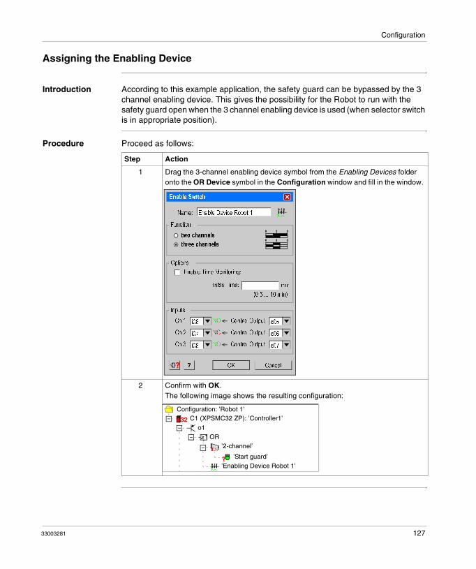
Configuration
Assigning the Enabling Device
Introduction According to this example application, the safety guard can be bypassed by the 3 channel enabling device. This gives the possibility for the Robot to run with the safety guard open when the 3 channel enabling device is used (when selector switch is in appropriate position).
Procedure Proceed as follows:
Step Action
1 Drag the 3-channel enabling device symbol from the Enabling Devices folder onto the OR Device symbol in the Configuration window and fill in the window.
2 Confirm with OK.The following image shows the resulting configuration:
Enable Switch
Control Output:
CancelOK
c05
Enable Device Robot 1Name:
two channels
Control Output: c06
?
Function
Inputs
Ch 1: i06
Ch 2: i07
Enable Time: min
(0.5 ... 10 min)
Enable Time Monitoring:
three channels
Options
Control Output: c07Ch 3: i08
NO
NC
NO
Configuration: ’Robot 1’C1 (XPSMC32 ZP): ’Controller1’i32
o1OR
’2-channel’
’Start guard’’Enabling Device Robot 1’
1
33003281 127
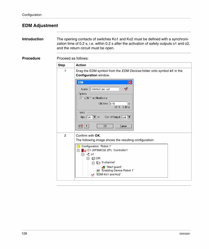
Configuration
EDM Adjustment
Introduction The opening contacts of switches Ko1 and Ko2 must be defined with a synchroni-zation time of 0.2 s, i.e. within 0.2 s after the activation of safety outputs o1 and o2, and the return circuit must be open.
Procedure Proceed as follows:
Step Action
1 Drag the EDM symbol from the EDM Devices folder onto symbol o1 in the Configuration window.
2 Confirm with OK.The following image shows the resulting configuration:
EDM
EDM Ko1 and Ko2Name:
Control Output:
CancelOK
c04
?
Inputs
Input: i04
0.15EDM Time:
(0.15 .. 0.50 s)
Options
EDM Time Monitoring:
s
Configuration: ’Robot 1’C1 (XPSMC32 ZP): ’Controller1’i32
o1OR
’2-channel’
’Start guard’’Enabling Device Robot 1’
’EDM Ko1 and Ko2’
1
128 33003281
Configuration
Assign a Name and a Stop Category to a Safety Output
Procedure Proceed as follows:
Step Action
1 Click the right mouse button on its function symbol in the Configuration window to assign a name and a stop category to safety output o1.
2 Select the Properties menu option. Indicate a name and the stop category.
Note: Any safety output not modified has a default stop category of 0.
3 Confirm with OK.Result: This completes the configuration of safety output o1.
Output
Delay Off Input:
CancelOK
Safety GuardName:
Stop Category 0
Stop Category 1
Delay Time:
(0.15 .. 300 s)
Interruption of Delay Time:
Control Output:
? ?
s
33003281 129

Configuration
Copying the State of One Safety Output onto another Safety Output
Description In our example, o2 represents the 2nd channel of a safety control system, and must consequently behave exactly like o1. Left-click o1 in the configuration window, then drag and drop it onto o2.
The global protection door function is then configured for safety outputs o1 and o2.
Your screen should look like the one below:
File Edit Mode Check Controller Options Help
XPSMCWin
Device Library: Configuration:
i i
Configuration Mode Configuration changed. Com5
i
i16XPSMC16 ZC - CANopen Extensioni
EDM Devices
Start Devices
Miscellaneous Devices
Enabling Devices
Configuration: ’Robot 1’Controller
State of Outputs
C1 (XPSMC32 ZP): ’Controller 1’iXPSMC16 Z
XPSMC16 ZP - Profibus Extensioni
XPSMC16 Xi
XPSMC32 Zi32XPSMC32 ZC - CANopen Extensioni32XPSMC32 ZP - Profibus Extensioni32
XPSMC32 Xi32
16
16
16
32
Monitoring Devices
o1: ’Safety guard’
OR
’2-channel’
’Start guard’
’Enable Device Robot 1’
’EDM Ko1 and Ko2’
o2
o1(C1)
o3
o4
o5
o6
R1
R2
1
Inputs left: 25 I Load: 15 %
Telemecanique
130 33003281

Configuration
5.3 Configuring the Emergency Stop Function
At a Glance
Overview This section contains the configuration description of the Emergency Stop function.
What's in this Section?
This section contains the following topics:
Topic Page
Emergency Stop 132
Master E-Stop Device 136
33003281 131

Configuration
Emergency Stop
Description Depending on the application, the machine’s global control system must be able to be stopped by means of Emergency Stop button S1 which activates free outputs 13 / 14 and 23 / 24 of relay group R1. Their contactors KE1 and KE2 are assigned to ensure that when the machine is started, KE1 and KE2 are stopped in a statutory fashion.
Procedure Proceed as follows:
Step Action
1 Drag the Two-Channel Emergency Stop symbol from the Emergency Stop folder (which is located in the Monitoring Devices folder) onto the output symbol of R1 in the Configuration window, and fill in the window.
2 Confirm with OK.Result: Now the E-Stop device is assigned to the safety relays group R1.
3 To also assign it to the solid state output o1, click with the right mouse button on the E-Stop device in the Configuration window.
4 Choose Copy from the selection.Result: The E-Stop device will then be copied with all its properties.
5 Click with right mouse button on the symbol of the output o1.
Emergency Stop
Control Output:
OKCancel
c08
Emergency Stop compl. machineName:
one channel switch
two channel switch
Control Output: c01
?
Function
Inputs
Ch 1: i09
Ch 2: i10
132 33003281

Configuration
6 Select Paste and as copy of device.Result: The E-Stop device will now also act on the output o1, and as the output state o1 is linked with o2, it will also act on o2.Note: To view the copies of a device, right click the mouse on the device. Mark e.g. E-Stop and select the menu Mark Copies. On the copies a green bubble appears. To remove the bubbles click Unmark Copies.
7 To adjust the return circuit, drag the EDM device symbol from the EDM Devices folder onto the symbol for R1 in the Configuration window, fill in the dialog box in accordance with the application.
Step Action
’EDM Ko1 and Ko2’
’Emergency Stop compl. Machine’
o1(C1)
’Emergency Stop compl. Machine’
’EDM E-Stop’
o2
o3
o4
o5
o6
R1
2
2
?
?
EDM
EDM E-StopName:
Control Output:
CancelOK
c02
?
Inputs
Input: i12
EDM Time:
(0.1 ... 0.5 s)
Options
EDM Time Monitoring:
s
33003281 133
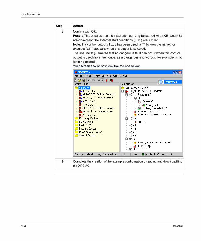
Configuration
8 Confirm with OK.Result: This ensures that the installation can only be started when KE1 and KE2 are closed and the external start conditions (ESC) are fulfilled.Note: If a control output c1...c8 has been used, a "*" follows the name, for example "c2*", appears when this output is selected.The user must guarantee that no dangerous fault can occur when this control output is used more then once, as a dangerous short-circuit, for example, is no longer detected.Your screen should now look like the one below:
9 Complete the creation of the example configuration by saving and download it to the XPSMC.
Step Action
File Edit Mode Check Controller Options Help
XPSMCWin
Device Library: Configuration:
i i
Configuration Mode Configuration changed. Com5
i
i16
XPSMC16 ZC - CANopen Extensioni
EDM Devices
Start Devices
Miscellaneous Devices
Enabling Devices
Controller
State of Outputs
XPSMC16 Z
XPSMC16 ZP - Profibus Extensioni
XPSMC16 Xi
XPSMC32 Zi32
XPSMC32 ZC - CANopen Extensioni32
XPSMC32 ZP - Profibus Extensioni32
XPSMC32 Xi32
16
16
16
Monitoring Devices
Inputs left: 25 I Load: 15 %
Telemecanique
Configuration: ’Robot 1’
C1 (XPSMC32 ZP): ’Controller1’i 32
o1: ’Safety guard’
OR
’2-channel’
’Start guard’’Enabling Device Robot 1’
’EDM Ko1 and Ko2’
o2
o1(C1)
o3
o4
o5
o6
R1
R2
1
’Emergency Stop compl. machine’
’EDM E-Stop’
’Emergency Stop compl. machine’
134 33003281

Configuration
LOSS OF SAFETY INPUT CROSS-CONNECTION DETECTION
Ensure that no more than one critical safety input is connected to each of the control outputs.
Failure to follow these instructions can result in death, serious injury, or equipment damage.
WARNING
33003281 135

Configuration
Master E-Stop Device
Description A E-Stop device acts as a Master E-Stop on all the other devices of the output. The other devices will be deactivated when the Master E-Stop is pressed. When this occurs, the start of this output is not possible until the start conditions of all the other devices are met.
This is also available for all the copies of the E-Stop devices.
Note: An output state does not transfer a master E-Stop command on other devices. Only the status itself is transferred.
136 33003281

Configuration
5.4 Save the Configuration
Save
Description The configuration can be saved by opening the File → Save menu option (or by
clicking on the floppy disk symbol button ) under the current name or by opening the File → Save As... option and assigning a new path/name.
Note: When you close the configuration file and then open it again, a back-up copy is created in the same directory, with a .mcb extension. This way your last saved and closed configuration is stored as a back-up file.
33003281 137

Configuration
138 33003281

Configuration
5.5 Requesting/Changing the Password
Password
Enter Password
Each XPSMC command involving quitting the RUN mode (setting up the XPSMC for example) must be confirmed with a password. If such a command is performed, a dialogue window opens in which the password must be entered.
Change Password
The default password is safety; as a safety measure, it must be changed to an individual password. The password must contain between 4 and 12 symbols. Any combination of letters and numbers may be used.
The password can be modified with command Controller → Change password.
Note: Your PC must be connected to the XPSMC safety controller.
Note: The password is case sensitive. Security and security are thus two different passwords.
33003281 139

Configuration
140 33003281

Configuration
5.6 Sending a Configuration from the PC to the XPSMC and Performing a Check
Sending a Configuration
Procedure To send a completed configuration from the PC to the safety controller, follow this procedure:
Step Action
1 Select Check → Check Configuration to check the configuration.You can click on the Check Configuration icon alternatively:
Result: If the configuration contains no errors, the following message box appears:
If the configuration contains errors, a yellow question mark will be seen, and a corresponding message box will appear.
File Edit Mode Check Controller Options Help
i i
XPSMCWIN
OK
No errors found.
33003281 141

Configuration
2 Go to Controller → Download Configuration to Controller to download the configuration:
You can click on the Configuration icon alternatively:
Step Action
File Edit Mode Check
XPSMCWIN
Device Library:
i i
i
i16XPSMC16 ZC - CANopen Extensioni
EDM Devices
Start Devices
Controller
XPSMC16 Z
XPSMC16 ZP - Profibus Extensioni
XPSMC16 Xi
XPSMC32 Zi32XPSMC32 ZC - CANopen Extensioni32XPSMC32 ZP - Profibus Extensioni32
XPSMC32 Xi32
16
16
16
Monitoring Devices
Run Controller
Change Password
Download Configuration to Controller
Upload Configuration from Controller
Stop Controller
Validated Copy
Read Validation
Read Protocol from Controller
Open Protocol
Controller Setup (Bus Configuration)
Download Setup to Controller
Controller Info
COM Settings ...
i
i
i
i
Options HelpController
Controller Options Help
Configuration
i i
142 33003281
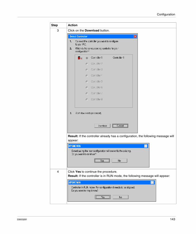
Configuration
3 Click on the Download button.
Result: If the controller already has a configuration, the following message will appear:
4 Click Yes to continue the procedure.Result: If the controller is in RUN mode, the following message will appear:
Step Action
Connect the controller you want to configureto your PC.
Which is the corresponding controller in yourconfiguration?
Start download (or cancel).
Select Controller
Controller 1 ‘Controller 1‘
CancelDownload
i 32
Controller 2
Controller 3
Controller 4
Controller 5
Controller 6
Controller 7
Controller 8
1.
2.
3.
Yes No
Downloading the new configuration will overwrite the existing.
XPSMCWIN
Do you want to continue?
NoYes
Controller in RUN mode. For configuration it needs to be stopped.
Do you want to stop it now?
XPSMCWIN
33003281 143

Configuration
5 Click Yes to continue the procedure.Result: To stop the controller, enter your password (default password is safety in lower case)
6 Click OK to continue.Result: The download procedure is starting.After the download, you will see the protocol:
Note: Read this protocol carefully and check it with your hardware configuration. With Validate you confirm the correctness of the software configuration in the controller shown in the protocol.
7 Click on Validate button to validate the protocol.
Step Action
Please enter the password:
OK Cancel
Password
******
Protocol
0000 ************************************************************************************0001 XPS-MC V2.260002 Build: DB0A0110C70A021AC70A021A0003 Configuration protocol0004 Controller number: 010005 Configuration name: Robot 10006 Configuration date: 2006/02/10 10:240007 ************************************************************************************0008 RESPONSETIME: 30ms0009 RESPONSETIME: Device Safety mat = 45ms0010 ************************************************************************************0011 Modbus parameter:0012 Address: 0010013 Bitrate: 192000014 Parity: even0015 Stopbits: 10016 ************************************************************************************0017 Profibus Parameter0018 Address: 0020019 Baudrate: Autodetect0020 ************************************************************************************0021 Assignment control outputs / inputs:0022 Control output group: 010023 Used inputs: 01, 10,0024 Control output group: 020025 Used inputs: 02, 12,
CancelValidate
i
144 33003281

Configuration
8 Enter your name in the Validation dialog box:
9 Click OK to continue.Result:The Password dialog box will be displayed:
10 Enter your password and click OK.
11 Click OK to continue.Result: The following message will be displayed:
12 Click Yes to upload the protocol.Result: The following message will be displayed:
Step Action
Validation
CancelOK
I
Your name (max. 20 characters):
Options
Allow copying of validated configuration from controller
Create a copy of validated configuration now
Please enter the password:
OK Cancel
Password
******
NoYes
Do you want to upload the protocol of the validation for your documentation now?
Alternatively you can upload it later by using the menu ‘Controller‘.
XPSMCWIN
OK
Configuration downloaded successfully.
XPSMCWIN
No
Do you want the controller in RUN mode now?
33003281 145

Configuration
13 Click OK to start the controller.Result: The following message will be displayed
14 Click OK to finish the procedure.
Step Action
OK
Controller is in RUN mode now.
XPSMCWIN
146 33003281

Configuration
Typical Configuration Errors
Configuration error 1: If you forgot to assign a start device to the Two-Channel Safety Guard, the main window and the message box will look as follows:
File Edit Mode Check Controller Options Help
XPSMCWin
Device Library: Configuration:
i i
i
i16
XPSMC16 ZC - CANopen Extensioni
EDM Devices
Start Devices
Miscellaneous Devices
Enabling Devices
Controller
State of Outputs
XPSMC16 Z
XPSMC16 ZP - Profibus Extensioni
XPSMC16 Xi
XPSMC32 Zi32
XPSMC32 ZC - CANopen Extensioni32
XPSMC32 ZP - Profibus Extensioni32
XPSMC32 Xi32
16
16
16
Monitoring Devices
Configuration: ’Robot 1’
C1 (XPSMC32 ZP): ’Controller1’i32
o1: ’Safety guard’
OR
’2-channel’
’Start guard’
’Enabling Device Robot 1’
’EDM Ko1 and Ko2’
o2
o1(C1)
o3
o4
o5
o6
R1
R2
1
’Emergency Stop compl. machine’
’EDM E-Stop’
’Emergency Stop compl. machine’
?
XPSMCWIN
OK
MISSING START DEFINITION.
Some devices require a start to be defined but haven’t by now.Please see the yellow question mark(s) in configuration tree and attach a start device to the marked items(s).
33003281 147
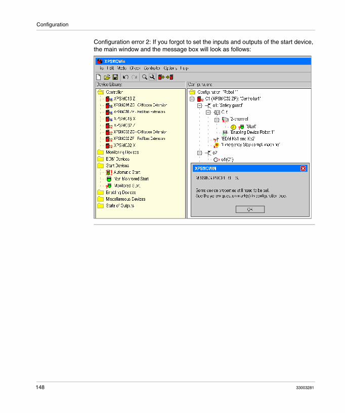
Configuration
Configuration error 2: If you forgot to set the inputs and outputs of the start device, the main window and the message box will look as follows:
File Edit Mode Check Controller Options Help
XPSMCWin
Device Library: Configuration:
i i
i
i16XPSMC16 ZC - CANopen Extensioni
EDM Devices
Start Devices
Miscellaneous Devices
Enabling Devices
Controller
State of Outputs
XPSMC16 Z
XPSMC16 ZP - Profibus Extensioni
XPSMC16 Xi
XPSMC32 Zi32XPSMC32 ZC - CANopen Extensioni32XPSMC32 ZP - Profibus Extensioni32
XPSMC32 Xi32
16
16
16
Monitoring Devices
Configuration: ’Robot 1’
C1 (XPSMC32 ZP): ’Controller1’i 32
o1: ’Safety guard’
OR
’2-channel’
’Start’
’Enabling Device Robot 1’
’EDM Ko1 and Ko2’
o2
o1(C1)
o3
o4
o5
o6
R1
R2
1
’Emergency Stop compl. machine’
’EDM E-Stop’
’Emergency Stop compl. machine’
?
XPSMCWIN
OK
MISSING PROPERTIES.
Some device properties still need to be set.See the yellow question mark(s) in configuration tree.
Automatic Start
Non-Monitored Start
Monitored Start
148 33003281

Configuration
5.7 Loading a Configuration
Loading
Description The configuration of a controller can be uploaded at any time without stopping the controller.
Procedure Proceed as follows:
Step Action
1 Connect your PC to the XPSMC safety controller.
2 Choose the command Controller → Upload Configuration from Controller or
click on the button in the toolbar.Reaction: The configuration is loaded from the XPSMC and then represented in the usual tree structure.
i
33003281 149

Configuration
150 33003281

Configuration
5.8 Creation/Transfer of a Validated Configuration Copy
At a Glance
Overview This section contains the description of creation and transfer a validated configuration copy.
What's in this Section?
This section contains the following topics:
Topic Page
Copy/Saving of a Validated Configuration 152
Transfer of a Validated Configuration Copy 153
33003281 151

Configuration
Copy/Saving of a Validated Configuration
Condition As a condition to create a copy of a validated configuration, the Enable copying of validated configuration from controller option must be selected during the validation of the configuration, see also Sending a Configuration, p. 141, step for the validation. Under this condition the user is able to make a copy of the validated configuration from the XPSMC into a binary file at any time. In addition, the Create a copy of the validated configuration now option can be selected in order to immediately create such a copy during the validation.
Copy of a Validated Configuration
Included with the configuration itself, the following data of the original controller is taken:� validation counter (VDC)� password� validation data (name, date)� device parameters (Modbus parameters, controller number)
This file can be used as a safety copy to transfer the validated configuration to another controller without the need of a new validation.
Saving a Validated Configuration
Proceed as follows:
Step Action
1 Connect the PC to the controller containing the validated configuration which is free for copy.
2 Choose the command Controller → Create validated copy.Result: The configuration will be read out of the controller.
3 Enter the save location and file name in the window which appears.Result: The copy will be saved as this file.
152 33003281

Configuration
Transfer of a Validated Configuration Copy
Description When a file with a copy of a validated configuration has been made (see chapter Copy/Saving of a Validated Configuration, p. 152) for a certain controller, it is easy to transfer the configuration into another controller, especially for replacement of a XPSMC unit for service or for installation of controllers in identical machines.
Procedure 1 - New Controller
Proceed as follows:
Step Action
1 Connect the PC to the controller in which the validated configuration is to be transferred.Result: The controller is not configured, the Power LED is on, and the CNF LED is blinking.
2 Choose the command Controller → Validated copy → Transfer validated copy to controller.Result: You get 2 messages:� Please connect the controller you want the configuration to transfer to and
press ’OK’ to start the transfer.� Transferring the copy will overwrite the existing configuration in the controller.
Do you want to continue?
3 Indicate in the appearing window the name of the validated configuration file.Result: The validated configuration is transferred into the connected controller.A message box tells you to powercycle the controller to start the new configuration.
33003281 153

Configuration
Procedure 2 -Configured Controller, Password Available
Proceed as follows:
Procedure 3 - Configured Controller, Password Unavailable
Reset the controller by pressing the Reset button and simultaneously performing a power cycle. Then follow Procedure 1 - New Controller, p. 153.
Validated Configuration into another Controller
The new controller now has the validated configuration, including the validation counter (VDC), the password, the validation data (name, date) and the device parameters (Modbus parameters, controller number).
It can be used like the original controller from which the copy was made from, except that the running time (OPC) of the configuration is set to zero.
Step Action
1 Connect the PC to the controller in which the validated configuration is to be transferred.
2 Choose the command Validated copy → Transfer validated copy to controller.Note: If the controller is running, another message box reminds you that the controller has to be stopped. You will also be reminded to enter your password. If you do not have a password, you will have to reset the controller by powercycling it and simultaneously pressing the Reset button. See also Procedure 1 - New Controller, p. 153 for downloading a validated copy.
3 Indicate in the appearing window the name of the file.Result: The validated configuration is picked out from the file and transferred into the connected controller.A message box tells you that you have to powercycle the controller to start the new configuration and run the controller.
Note: To modify the configuration, you need the password of the validated configuration. The controller password has been overwritten.
154 33003281

Configuration
5.9 Read Protocol from Controller
Read Protocol from Controller
Procedure Proceed as follows:
Step Action
1 Connect the PC to the XPSMC safety controller.
2 The controller has to be put in Stop mode with the menu Controller → Stop Controller.
3 A window appears, and you are asked to enter your password to stop the controller.
4 Choose the menu Controller → Read Protocol from Controller.Result: The protocol will be displayed in a separate window and can be printed.Note: This print is just a work tool.The only proof of the correctness of the configuration is the validated and signed protocol. (See chapter Sending a Configuration, p. 141)
33003281 155

Configuration
156 33003281

33003281
6
DiagnosisXPSMC Safety Controller Diagnostics
Introduction Various states of an XPSMC can be loaded from a PC for fault diagnostics and error finding purposes.
Procedure The fault Diagnostic mode is activated as follows:
Note: During the fault diagnostics, the XPSMC continues to operate without being influenced, to allow the progress of a complete machine cycle to be monitored.
Step Action
1 Connect your PC to the XPSMC safety controller in operation.
2 Start the XPSMCWIN software.
3 Open a configuration from a file or upload the configuration from the controller.Note: During the opening of a saved configuration from a file, the configuration must correspond to the one already in the controller. The controller configuration must have been validated.
4 Choose the Diagnostic mode. To do this, choose the menu Mode → Diagnostic
or click on the icon for the Diagnostic mode. Result: The window will become grey, to show that no modifications can be made.
157

Diagnosis
Color Definitions In the Configuration window, a colored circle is placed next to each function symbol of the configuration tree.
The color indicates the current status of the corresponding function:
Meaning of symbols
Symbols Meaning
Red Point The safety output concerned is deactivated, or this device has not been validated (for example, protection door open, Emergency Stop not initiated, etc.), or the concerned input is opened.
Red Point with a Yellow Flash An error exists for this device (input/output). The error message will then be shown by clicking on the device.
Green Point The safety output concerned is activated, or this device has been validated (for example, protection door closed, emergency stop initiated, etc.), or the concerned input is closed.
File Mode Diagnosis Options HelpXPSMCWIN 2.00
Device Library Configuration
Monitoring DevicesEDM DevicesStart Devices
Miscellaneous DevicesEnabling Devices
i i
Diagnostic Mode Diagnostic running Com5
ConfigurationController
State of Outputs
C1 [XPSMC32 ZP]: ’Controller1’i32
[259] o1[257] ’Emergency Stop’
i01: ’Ch. 1’
i
Telemecanique
Device [257] : Short circuit between inputs.
[261] o2[260] ’Light Curtain’
[258] Auto Start ’Auto. Start’i02: ’OSSD 1’
i03: ’OSSD 2’
o3o4o5o6[262] R1
[260] ’Light Curtain’[258] Auto Start ’Auto. Start’i02: ’OSSD 1’
i03: ’OSSD 2’R2
158 33003281
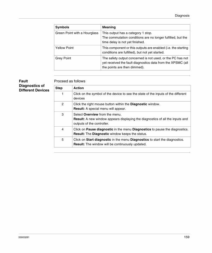
Diagnosis
Fault Diagnostics of Different Devices
Proceed as follows
Green Point with a Hourglass This output has a category 1 stop.The commutation conditions are no longer fulfilled, but the time delay is not yet finished.
Yellow Point This component or this outputs are enabled (i.e. the starting conditions are fulfilled), but not yet started.
Grey Point The safety output concerned is not used, or the PC has not yet received the fault diagnostics data from the XPSMC (all the points are then dimmed).
Symbols Meaning
Step Action
1 Click on the symbol of the device to see the state of the inputs of the different devices
2 Click the right mouse button within the Diagnostic window.Result: A special menu will appear.
3 Select Overview from the menu.Result: A new window appears displaying the diagnostics of all the inputs and outputs of the controller.
4 Click on Pause diagnostic in the menu Diagnostics to pause the diagnostics. Result: The Diagnostic window keeps the status.
5 Click on Start diagnostic in the menu Diagnostics to start the diagnostics.Result: The window will be continuously updated.
33003281 159

Diagnosis
160 33003281

Appendices
At a glance
Overview Additional information that is not necessarily required for an understanding of the documentation.
What's in this Appendix?
The appendix contains the following chapters:
Chapter Chapter Name Page
A Wiring (Examples) and Functional Diagrams 163
33003281 161

Appendices
162 33003281

33003281
A
Wiring (Examples) and Functional DiagramsAt a Glance
Overview This chapter contains examples of wiring and functional diagrams.
Note: The data for safety categories in accordance with EN 954-1 refers to the maximum achievable categories. The machine control must also be appropriately configured in order to achieve the desired category.
163

Wiring and Functional Diagrams
What's in this Chapter?
This chapter contains the following topics:
Topic Page
Electrical Diagram for the XPSMC 165
Three One-Channel Emergency Stops, with Automatic Start 167
Two Two-Channel Emergency Stop, with Start Button 169
Safety Guard with One Channel 171
Two Channel Safety Guard 174
Two Channels Safety Guard with Lock 178
Light Curtain with Relay Outputs 182
Light Curtain with Transistor Outputs 186
Muting for Light Curtains Type 4 190
Magnetic Switch 192
Two-Hand Control 196
Safety Mat 198
Zero Speed Detection 200
Injection Molding Machines 204
Hydraulic Press Valve Monitoring 207
Hydraulic Press 2 209
Eccentric Press 215
Eccentric Press 2 219
Selector Switch 224
Timer 226
Shaft/Chain-Break Monitoring 229
Seat Valve Monitoring 231
Enabling Device 2 Channel 233
Enabling Device 3 Channel 235
Foot Switch 237
164 33003281

Wiring and Functional Diagrams
Electrical Diagram for the XPSMC
Response Time When not other mentioned the following drawings show a XPSMC16 with a response time of 20 ms.
Wiring Diagram
XPSMC16 / XPSMC32
The static outputs are rated category 4 according to EN954-1.
HAZARDOUS VOLTAGE
Disconnect all power before servicing equipment.
Failure to follow these instructions will result in death or serious injury.
DANGER
XPSMC16safety controllerT
A1 c8 c7 c6 c5 c4 c3 c2 c1
A2 GND GND GND o1 o2 o3 o4 o5 o6 14 24 34 44
13 23 H1 33 34
K3
K4
K1
K2
Channel 1
Channel 2
Channel 1
Channel 2
Channel 1
Channel 2
Channel 1
Channel 2
Channel 1
Channel 2
Channel 1
Channel 2
TERK0
µC 1
µC 1
LOGIC
24 V
5 V
XPSMC16
XPSMC32
XPSMC32safety controllerT
A1 c8 c7 c6 c5 c4 c3 c2 c1
A2 GND GND GND o1 o2 o3 o4 o5 o6 14 24 34 44
i1 i2 i3 i4 i5 i6 i7 i8 i9 i10 i11 i12 i13 i14 i15 i16 13 23 H1 33 34
K3
K4
K1
K2
Channel 1
Channel 2
Channel 1
Channel 2
Channel 1
Channel 2
Channel 1
Channel 2
Channel 1
Channel 2
Channel 1
Channel 2
TERK0
µC 1
µC 1
LOGIC
24 V
5 V
c8 c7 c6 c5 c4 c3 c2 c1 ... i32i17
i1 i2 i3 i4 i5 i6 i7 i8 i9 i10 i11 i12 i13 i14 i15 i16
33003281 165

Wiring and Functional Diagrams
Technical Data Description of terminals
Terminal Layout Meaning
A1-A2 24V power supply; A1 is the + pole (+24 VDC), A2 is the - pole (0 VDC, GND)
GND It is identical to the 0 V potential on A2 for loads on the o1...o6 semiconductor safety outputs.
c1-c8 control outputs for safety input power supplyThe control outputs contain a signal which enables short circuit detection monitoring, voltage intrusion and open circuit detection for all connected control components.
i1-i16 or i1-i32 safety inputs
H1 connection for muting lamp
o1-o6 semiconductor safety outputs
13/14, 23/24, 33/34, 43/44
safety outputs, potential free
TER 8 pin RJ45 connector used to connect the XPSMC safety controller to a PC for configuration and/or diagnostics. The communication via the TER terminal is Modbus RTU protocol and can also be used to connect to a HMI magelis operating terminal, or a standard PLC.
Fieldbus connector for a fieldbus dependant on version:� Profibus DP: 9 pin D-SUB female connector� CANopen: 9 pin D-SUB male connector.
166 33003281

Wiring and Functional Diagrams
Three One-Channel Emergency Stops, with Automatic Start
Functional Diagram
The following diagram shows three One-Channel Emergency Stops and the relevant control outputs for categories 0 and 1:
OperationEmergency
Stop
OperationEmergency
Stop
Operation
InputEmergency Stop 1
InputEmergency Stop 2
InputEmergency Stop 3
Relay Outputs K1/K2Stop Category 0
Relay Outputs K3/K4Stop Category 1
tv = 0.1…300 s tv = 0.1…300 s
33003281 167

Wiring and Functional Diagrams
Wiring Diagram The following image shows the wiring diagram of the One-Channel Emergency Stop:
(1) See Technical Data in XPSMC safety controller Hardware manual for maximum fuse sizes.
The static outputs are rated category 4 according to EN954-1.
F1(1)
Safety ControllerXPSMC16T
A2 GNDGNDGND o1 o2 o3 o4 o5 o6 14 24 34 44
K3
K4
K1
K2
Channel 1
Channel 2
Channel 1
Channel 2
Channel 1
Channel 2
Channel 1
Channel 2
Channel 1
Channel 2
Channel 1
Channel 2
K0
µC 1
µC 1
LOGIC
24 V
5 V
0V
230V ~ 230V ~
A1 c8 c7 c6 c5 c4 c3 c2 c1 i1 i2 i3 i4 i5 i6 i7 i8 i9 i10 i11 i12 i13 i14 i15 i16 13 23 H1 33 34
TERFieldbus
0V
EmergencyStop
F2(1)
+24 V +24 V
F3(1)
Emergency Stop Category 0
S1
Emer-gencyStop 1
S2
Emer-gencyStop2
S3
Emer-gencyStop3
Note: A jumper between the 2 terminals of an Emergency Stop will not be recognised. Short-circuit between i1, i2, i3 will be recognised.
168 33003281

Wiring and Functional Diagrams
Two Two-Channel Emergency Stop, with Start Button
Functional Diagram
The following functional diagram shows two Two-Channel Emergency Stops and the relevant control outputs for Categories 0 and 1:
OperationEmergency
Stop
OperationEmergency
StopOperation
Input Emergency Stop 1Channel 1
Input Emergency Stop 1Channel 2
Input Emergency Stop 2Channel 1
Input Emergency Stop 2Channel 2
InputStart
Output o1Stop Category 0
Output o2Stop Category 1
tv = 0.1…300s tv = 0.1…300s
33003281 169

Wiring and Functional Diagrams
Wiring Diagram The following wiring diagram shows two Two-Channel Emergency Stops and the relevant control outputs for the Categories 0 and 1:
(1) See Technical Data in XPSMC safety controller Hardware manual for maximum fuse sizes.
The static outputs are rated category 4 according to EN954-1.
0 V 0 V
F1(1)
XPSMC16safety controllerT
A2 GNDGNDGND o1 o2 o3 o4 o5 o6 14 24 34 44
K3
K4
K1
K2
Channel 1
Channel 2
Channel 1
Channel 2
Channel 1
Channel 2
Channel 1
Channel 2
Channel 1
Channel 2
Channel 1
Channel 2
TERK0
µC 1
µC 1
LOGIC
24 V
5 V
+24 V +24 V
S3S2S1
A1 c8 c7 c6 c5 c4 c3 c2 c1 i1 i2 i3 i4 i5 i6 i7 i8 i9 13 23 H1 33 34
Emer-
gency
Push
Button
StartEmer-
gency
Push
Button
Emergency stop category 0
Emergency stop category 1
i10 i11 i12 i13 i14 i15 i16
170 33003281

Wiring and Functional Diagrams
Safety Guard with One Channel
Functional Diagram
The following functional diagram shows the Safety Guard with One Channel with Start Interlock and different Start Functions:
Start Function Start Interlock = YES
Automatic Start
Monitored StartRising Edge
Monitored StartFalling Edge
InputLimit switch
Output
Guardopened
Guardclosed
GuardclosedP
ower
no start
Input Limit Switch
Output
Guardopened
Guardclosed
GuardclosedP
ower
no start
Input MonitoredStart
Input LimitSwitch
Output
Guardopened
Guardclosed
GuardclosedP
ower
no start
Input MonitoredStart
33003281 171

Wiring and Functional Diagrams
The following functional diagram shows the Safety Guard with One Channel without Start Interlock and different Start Functions:
Start Function Start Interlock = NO
Automatic Start
Monitored StartRising Edge
Monitored StartFalling Edge
InputLimit switch
Output
Guardopened
Guardclosed
GuardclosedP
ower
InputLimit switch
Output
Guardopened
Guardclosed
GuardclosedP
ower
Input MonitoredStart
Input LimitSwitch
Output
Guardopened
Guardclosed
GuardclosedP
ower
Input MonitoredStart
172 33003281

Wiring and Functional Diagrams
Wiring Diagram The following wiring diagram shows the Safety Guard with One Channel with and without Start Interlock and different Start Functions:
(1) See Technical Data in XPSMC safety controller Hardware manual for maximum fuse sizes.
The static outputs are rated category 4 according to EN954-1.
F1(1)
Safety ControllerXPSMC16T
A2 GNDGNDGND o1 o2 o3 o4 o5 o6 14 24 34 44
K3
K4
K1
K2
Channel 1
Channel 2
Channel 1
Channel 2
Channel 1
Channel 2
Channel 1
Channel 2
Channel 1
Channel 2
Channel 1
Channel 2
K0
µC 1
µC 1
LOGIC
24 V
5 V
0V
230V ~ 230V ~
A1 c8 c7 c6 c5 c4 c3 c2 c1 i1 i2 i3 i4 i5 i6 i7 i8 i9 i10 i11 i12 i13 i14 i15 i16 13 23 H1 33 34
TERFieldbus
0V
S1
Start
S2
������������������������������������������������������������������������
open
Release
F2(1)
+24 V +24 V
33003281 173

Wiring and Functional Diagrams
Two Channel Safety Guard
Functional Diagram
The following functional diagram shows the Two-Channel Safety Guard with Start Interlock and different Start Functions:
Start Function Start Interlock = YES
Automatic Start
Monitored StartRising Edge
Input limit switch1
Input EDM
Guardopened
Guardclosed
GuardclosedP
ower
Input limit switch2
Output t < t EDM
t < t syn.
no start
EDM: External Device Monitoring
Input limit switch1
Input monitoredstart
Guardopened
Guardclosed
GuardclosedP
ower
Input limit switch2
Input EDM
t < t syn.
no start
Outputt < t EDM
EDM: External Device Monitoring
174 33003281

Wiring and Functional Diagrams
The following functional diagram shows the Two-Channel Safety Guard without Start Interlock and different Start Functions:
Monitored StartFalling Edge
Start Function Start Interlock = NO
Automatic Start
Start Function Start Interlock = YES
Input limit switch1
Input monitoredstart
Guardopened
Guardclosed
GuardclosedP
ower
Input limit switch2
Input EDM
t < t syn.
no start
Outputt < t EDM
EDM: External Device Monitoring
Input limit switch1
Input EDM
Guardopened
Guardclosed
GuardclosedP
ower
Input limit switch2
Output t < t EDM
t < t syn.
t = t EDM
t > t EDM
EDM: External Device Monitoring
33003281 175

Wiring and Functional Diagrams
Monitored StartRising Edge
Monitored StartFalling Edge
Start Function Start Interlock = NO
Input limit switch1
Input monitoredstart
Guardopened
Guardclosed
GuardclosedP
ower
Input limit switch2
Input EDM
t < t EDM
t < t syn.
Output
EDM: External Device Monitoring
Input limit switch1
Input monitoredstart
Guardopened
Guardclosed
GuardclosedP
ower
Input limit switch2
Input EDM
t < t EDM
t < t syn.
Output
EDM: External Device Monitoring
176 33003281

Wiring and Functional Diagrams
Wiring Diagram The following wiring diagram shows the Two-Channel Safety Guard with and without Start Interlock and different Start Functions:
ESC External Start ConditionsEDM External Device Monitoring(1) See Technical Data in XPSMC Safety Controller Hardware manual for maximum fuse size
The static outputs are rated category 4 according to EN954-1.
F1(1)
Safety ControllerXPSMC16T
A2 GNDGNDGND o1 o2 o3 o4 o5 o6 14 24 34 44
K3
K4
K1
K2
Channel 1
Channel 2
Channel 1
Channel 2
Channel 1
Channel 2
Channel 1
Channel 2
Channel 1
Channel 2
Channel 1
Channel 2
K0
µC 1
µC 1
LOGIC
24 V
5 V
0V
+24 V +24 V
A1 c8 c7 c6 c5 c4 c3 c2 c1 i1 i2 i3 i4 i5 i6 i7 i8 i9 i10 i11 i12 i13 i14 i15 i16 13 23 H1 33 34
TERFieldbus
K01 K02
Channel 1 Channel 2
0V
ESC
K01
K02S1
Start
S2S3
���������������������������������������������������������������������
open
EDM
33003281 177
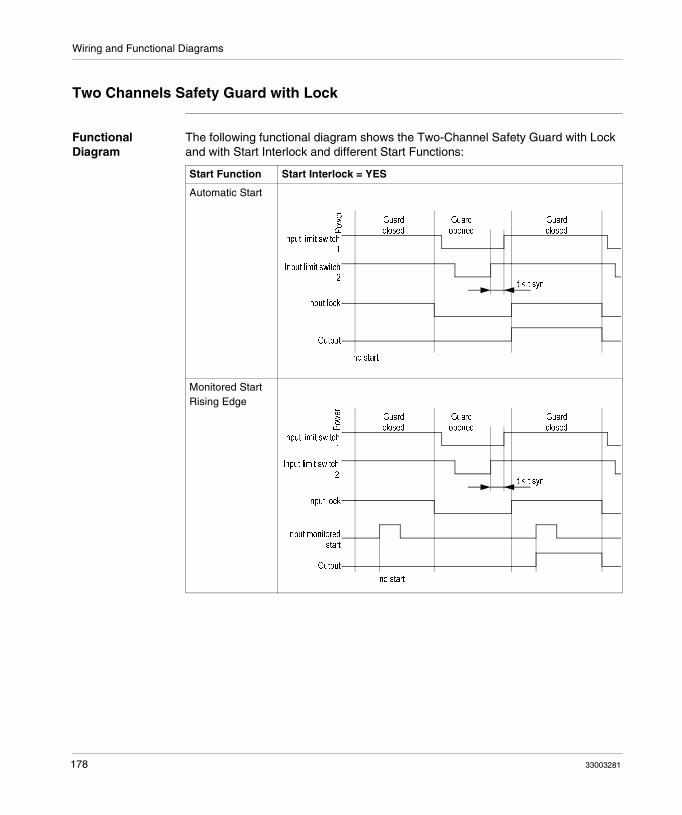
Wiring and Functional Diagrams
Two Channels Safety Guard with Lock
Functional Diagram
The following functional diagram shows the Two-Channel Safety Guard with Lock and with Start Interlock and different Start Functions:
Start Function Start Interlock = YES
Automatic Start
Monitored StartRising Edge
Input limit switch1
Input lock
Guardclosed
GuardclosedP
ower
Input limit switch2
Output
t < t syn.
Guardopened
no start
Input limit switch1
Input lock
Guardclosed
GuardclosedP
ower
Input limit switch2
Input monitoredstart
t < t syn.
Guardopened
Output
no start
178 33003281

Wiring and Functional Diagrams
The following functional diagram shows the Two-Channel Safety Guard with Lock and without Start Interlock and different Start Functions:
Monitored StartFalling Edge
Start Function Start Interlock = NO
Automatic Start
Start Function Start Interlock = YES
Input limit switch1
Input lock
Guardclosed
GuardclosedP
ower
Input limit switch2
Input monitoredstart
t < t syn.
Guardopened
Output
no start
Input limit switch1
Input lock
Guardclosed
GuardclosedP
ower
Input limit switch2
Output
t < t syn.
Guardopened
33003281 179

Wiring and Functional Diagrams
Monitored StartRising Edge
Monitored StartFalling Edge
Start Function Start Interlock = NO
Input limit switch1
Input lock
Guardclosed
GuardclosedP
ower
Input limit switch2
Input monitoredstart
t < t syn.
Guardopened
Output
Input limit switch1
Input lock
Guardclosed
GuardclosedP
ower
Input limit switch2
Input monitoredstart
t < t syn.
Guardopened
Output
180 33003281

Wiring and Functional Diagrams
Wiring Diagram The following wiring diagram shows the Two-Channel Safety Guard with Lock and with and without Start Interlock and different Start Functions:
ESC External Start ConditionsEDM External Device Monitoring(1) See Technical Data in XPSMC Safety Controller Hardware manual form maximum fuse
size
The static outputs are rated category 4 according to EN954-1.
������������
��������������
F1(1)
Safety ControllerXPSMC16T
A2 GNDGNDGND o1 o2 o3 o4 o5 o6 14 24 34 44
K3
K4
K1
K2
Channel 1
Channel 2
Channel 1
Channel 2
Channel 1
Channel 2
Channel 1
Channel 2
Channel 1
Channel 2
Channel 1
Channel 2
K0
µC 1
µC 1
LOGIC
24 V
5 V
0V
+24 V +24 V
A1 c8 c7 c6 c5 c4 c3 c2 c1 i1 i2 i3 i4 i5 i6 i7 i8 i9 i10 i11 i12 i13 i14 i15 i16 13 23 H1 33 34
TERFieldbus
K01 K02
Channel 1 Channel 2
0V
ESC
K01
K02
S3
Start
S4
open
EDM
���������������������������������������������������������������������
S2
S1 ������������
��������������
33003281 181

Wiring and Functional Diagrams
Light Curtain with Relay Outputs
Functional Diagram
The following functional diagram shows the Light Curtain with Relay Outputs with Start Interlock and different Start Functions:
Start Function Start Interlock = YES
Automatic Start
Monitored StartRising Edge
Input OSSD 1
Input EDM
Light curtainfree
Light curtain freeR
ising
Input OSSD 2
Output
t < t syn.
Light curtain inter-rupted
t < tEDMno start
OSSD: Output Safety Switching Device
Input OSSD1
Input monitoredstart
Light curtainfree
Light curtain freeR
ising
Input OSSD2
Input EDM
t < t syn.
Light curtain inter-rupted
t < tEMD no start
Output
OSSD: Output Safety Switching Device
182 33003281

Wiring and Functional Diagrams
The following functional diagram shows the Light Curtain with Relay Outputs without Start Interlock and different Start Functions:
Monitored StartFalling Edge
Start Function Start Interlock = NO
Automatic Start
Start Function Start Interlock = YES
Input OSSD1
Input monitoredstart
Light curtainfree
Light curtain freeR
ising
Input OSSD2
Input EDM
t < t syn.
Light curtain inter-rupted
t < tEDM no start
Output
OSSD: Output Safety Switching Device
Input OSSD 1
Input EDM
Light curtainfree
Light curtainR
ising
Input OSSD 2
Output
t < t syn.
Light curtain inter-rupted
t < t EDMt = t EDM
t > t EDM
OSSD: Output Safety Switching Device
33003281 183

Wiring and Functional Diagrams
Monitored StartRising Edge
Monitored StartFalling Edge
Start Function Start Interlock = NO
Input OSSD1
Input monitoredstart
Light curtainfree
Light curtainR
ising
Input OSSD2
Input EDM
t < t syn.
Light curtain inter-rupted
t < tEDMOutput
OSSD: Output Safety Switching Device
Input OSSD1
Input monitoredstart
Light curtainfree
Light curtainR
ising
Input OSSD2
Input EDM
t < t syn.
Light curtain inter-rupted
t < t EDMOutput
OSSD: Output Safety Switching Device
184 33003281

Wiring and Functional Diagrams
Wiring Diagram The following wiring diagram shows the Light Curtain with Relay Outputs with and without Start Interlock and different Start Functions:
ESC External Start ConditionsEDM External Device MonitoringESPE Electro Sensitive Protective EquipmentOSSD Output Safety Switching Device(1) See Technical Data in XPSMC Safety Controller Hardware manual form maximum fuse
size
The static outputs are rated category 4 according to EN954-1.
F1(1)
Safety ControllerXPSMC16T
A2 GNDGNDGND o1 o2 o3 o4 o5 o6 14 24 34 44
K3
K4
K1
K2
Channel 1
Channel 2
Channel 1
Channel 2
Channel 1
Channel 2
Channel 1
Channel 2
Channel 1
Channel 2
Channel 1
Channel 2
K0
µC 1
µC 1
LOGIC
24 V
5 V
0V
+24 V +24 V
A1 c8 c7 c6 c5 c4 c3 c2 c1 i1 i2 i3 i4 i5 i6 i7 i8 i9 i10 i11 i12 i13 i14 i15 i16 13 23 H1 33 34
TERFieldbus
K01 K02
Channel 1 Channel 2
0V
ESPE =ESPE output
S1
Start
ESC
K01
K02(1) (2)
(1)ESPE
OSSD1 OSSD2
EDM
(2)
33003281 185

Wiring and Functional Diagrams
Light Curtain with Transistor Outputs
Functional Diagram
The following functional diagram shows the Light Curtain with Transistor Outputs with Start Interlock and different Start Functions:
Start Function Start Interlock = YES
Automatic Start
Monitored StartRising Edge
Input OSSD1
Input EDM
Light curtainfree
Light curtain freeR
ising
Input OSSD2
Output
t < t syn.
Light curtain inter-rupted
t < tEDM
no start
OSSD: Output Safety Switching Device
Input OSSD1
Input monitoredstart
Light curtainfree
Light curtain freeR
ising
Input OSSD2
Input EDM
t < t syn.
Light curtain inter-rupted
t < tEDMno start
Output
OSSD: Output Safety Switching Device
186 33003281

Wiring and Functional Diagrams
The following functional diagram shows the Light Curtain with Transistor Outputs without Start Interlock and different Start Functions:
Monitored StartFalling Edge
Start Function Start Interlock = NO
Automatic Start
Start Function Start Interlock = YES
Input OSSD1
Input monitoredstart
Light curtainfree
Light curtain freeR
ising
Input OSSD2
Input EDM
t < t syn.
Light curtain inter-rupted
t < tEDMno start
Output
OSSD: Output Safety Switching Device
Input OSSD1
Input EDM
Light curtainfree
Light curtain freeR
ising
Input OSSD2
Output
t < t syn.
Light curtain inter-rupted
t < t EDMt = t EDM
t > t EDM
OSSD: Output Safety Switching Device
33003281 187

Wiring and Functional Diagrams
Monitored StartRising Edge
Monitored StartFalling Edge
Start Function Start Interlock = NO
Input OSSD1
Input monitoredstart
Light curtainfree
Light curtain freeR
ising
Input OSSD2
Input EDM
t < t syn.
Light curtain inter-rupted
t < tEDMOutput
OSSD: Output Safety Switching Device
Input OSSD1
Input monitoredstart
Light curtainfree
Light curtain freeR
ising
Input OSSD2
Input EDM
t < t syn.
Light curtain inter-rupted
t < t EDMOutput
OSSD: Output Safety Switching Device
188 33003281

Wiring and Functional Diagrams
Wiring Diagram The following wiring diagram shows the Light Curtain with Transistor Outputs with and without Start Interlock and different Start Functions
ESC External Start ConditionsEDM External Device MonitoringESPE Electro Sensitive Protective EquipmentOSSD Output Safety Switching Device(1) See Technical Data in XPSMC Safety Controller Hardware manual form maximum fuse
size
The static outputs are rated category 4 according to EN954-1.
F1(1)
Safety ControllerXPSMC16T
A2 GNDGNDGND o1 o2 o3 o4 o5 o6 14 24 34 44
K3
K4
K1
K2
Channel 1
Channel 2
Channel 1
Channel 2
Channel 1
Channel 2
Channel 1
Channel 2
Channel 1
Channel 2
Channel 1
Channel 2
K0
µC 1
µC 1
LOGIC
24 V
5 V
0V
+24 V +24 V
A1 c8 c7 c6 c5 c4 c3 c2 c1 i1 i2 i3 i4 i5 i6 i7 i8 i9 i10 i11 i12 i13 i14 i15 i16 13 23 H1 33 34
TERFieldbus
K01 K02
Channel 1 Channel 2
0V
ESPE =ESPE output
S1
Start
ES
K01
K02(-) (1) (2)
(+)ESPE
OSSD1 OSSD2
EDM
33003281 189

Wiring and Functional Diagrams
Muting for Light Curtains Type 4
Functional Diagram
The following functional diagram shows the Muting for light curtains type 4:
Start
Required
Input
Start
Input
Muting A1
Input
Muting B1
Input
Muting A2
Input
Muting B2
Input
Override
Output H1
Muting Lamp
Output
Channel 1
Output
Channel 2
Muting
t > t syn.
ESPE
Protects
Muting Active
Detection Zone By-Passed
ESPE
Protects
Muting
Fault
Outputs
Off
Override Active
Detection Zone by-
Passed
ESPE
Protects
t < t Muting
t < t syn.
t < t syn.
Detection Zone
Interrupted
t < t Override
Input
OSSD 1
Input
OSSD 2
Override (F)
Detection Zone
190 33003281

Wiring and Functional Diagrams
Wiring Diagram The following wiring diagram shows the Muting for light curtains type 4:
ESC External Start ConditionsEDM External Device MonitoringESPE Electro Sensitive Protective Equipment(1) See Technical Data in XPSMC Safety Controller Hardware manual form maximum fuse
size
The static outputs are rated category 4 according to EN954-1.
F1(1)
Safety ControllerXPSMC16T
A2 GNDGNDGND o1 o2 o3 o4 o5 o6 14 24 34 44
K3
K4
K1
K2
Channel 1
Channel 2
Channel 1
Channel 2
Channel 1
Channel 2
Channel 1
Channel 2
Channel 1
Channel 2
Channel 1
Channel 2
K0
µC 1
µC 1
LOGIC
24 V
5 V
0V
+24 V +24 V
A1 c8 c7 c6 c5 c4 c3 c2 c1 i1 i2 i3 i4 i5 i6 i7 i8 i9 i10 i11 i12 i13 i14 i15 i16 13 23 H1 33 34
TERFieldbus
K01 K02
Channel 1 Channel 2
0V
Muting lampESPE =ESPE output
S6
Override
S5
MutingB2
S3
MutingB1
S4
Muting
S2
Muting
S1
Start
ES
K01
K02(-) (1) (2)
(+)ESPE
OSSD1 OSSD2
H1
A1 A2
EDM
33003281 191

Wiring and Functional Diagrams
Magnetic Switch
Functional Diagram
The following functional diagram shows the Magnetic Switch with Interlock and different Start Functions:
Start Function Start Interlock = YES
Automatic Start
Monitored StartRising Edge
Input NC
MagnetpresentP
ower
Magnetabsent
t < t syn.
Magnetpresent
Input NO
Input EDM
Output
no start
t < tEDM
Input NC
MagnetpresentP
ower
Magnetabsent
t < t syn.
Magnetpresent
Input NO
Input monitoredstart
Input EDM
no startt < tEDM
Output
192 33003281
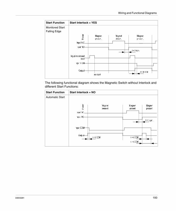
Wiring and Functional Diagrams
The following functional diagram shows the Magnetic Switch without Interlock and different Start Functions:
Monitored StartFalling Edge
Start Function Start Interlock = NO
Automatic Start
Start Function Start Interlock = YES
Input NC
MagnetpresentP
ower
Magnetabsent
t < t syn.
Magnetpresent
Input NO
Input monitoredstart
Input EDM
no startt < tEDM
Output
Input NC
MagnetpresentP
ower
Magnetabsent
t < t syn.
Magnetpresent
Input NO
Input EDM
Outputt < t EDM t = t EDM
t > t EDM
33003281 193

Wiring and Functional Diagrams
Monitored StartRising Edge
Monitored StartFalling Edge
Start Function Start Interlock = NO
Input NC
Magnetpresent
Power Magnet
absent
t < t syn.
Magnetpresent
Input NO
Input monitoredstart
Outputt < tEDM
Input EDM
Input NC
MagnetpresentP
ower
Magnetabsent
t < t syn.
Magnetpresent
Input NO
Input monitoredstart
Outputt < t EDM
Input EDM
194 33003281

Wiring and Functional Diagrams
Wiring Diagram The following wiring diagram shows the Magnetic Switch with and without Interlock and different Start Functions
ESC External Start ConditionsEDM External Device Monitoring(1) See Technical Data in XPSMC Safety Controller Hardware manual form maximum fuse
size
The static outputs are rated category 4 according to EN954-1.
F1(1)
Safety ControllerXPSMC16T
A2 GNDGNDGND o1 o2 o3 o4 o5 o6 14 24 34 44
K3
K4
K1
K2
Channel 1
Channel 2
Channel 1
Channel 2
Channel 1
Channel 2
Channel 1
Channel 2
Channel 1
Channel 2
Channel 1
Channel 2
K0
µC 1
µC 1
LOGIC
24 V
5 V
0V
+24 V +24 V
A1 c8 c7 c6 c5 c4 c3 c2 c1 i1 i2 i3 i4 i5 i6 i7 i8 i9 i10 i11 i12 i13 i14 i15 i16 13 23 H1 33 34
TERFieldbus
K01 K02
Channel 1 Channel 2
0V
ESC
K01
K02S2
Start
S1 =Magnetic switch
EDM
BK BU
WH BN+
Mag-net NC NO
S1
33003281 195

Wiring and Functional Diagrams
Two-Hand Control
Functional Diagram
The following functional diagram shows the Two-Hand Control device:
Two-Hand-Control
Activated
Two-Hand-Control
Not Activated
Two-Hand-Control
Activated
Input Push Button 1NO
Input Push Button 1NC
Input Push Button 2NO
Input Push Button 2NC
Output
No Start
t < 500ms
Power ON (RUN)
196 33003281

Wiring and Functional Diagrams
Wiring Diagram The following wiring diagram shows the Two-Hand Control device:
(1) See Technical Data in XPSMC safety controller Hardware manual for maximum fuse sizes.
The static outputs are rated category 4 according to EN954-1.
F1(1)
Safety ControllerXPSMC16T
A2 GNDGNDGND o1 o2 o3 o4 o5 o6 14 24 34 44
K3
K4
K1
K2
Channel 1
Channel 2
Channel 1
Channel 2
Channel 1
Channel 2
Channel 1
Channel 2
Channel 1
Channel 2
Channel 1
Channel 2
K0
µC 1
µC 1
LOGIC
24 V
5 V
0V
+24 V +24 V
A1 c8 c7 c6 c5 c4 c3c2 c1 i1 i2 i3 i4 i5 i6 i7 i8 i9 i10 i11 i12 i13 i14 i15 i16 13 23 H1 33 34
TERFieldbus
Channel 1 Channel 2
Valves
0V
S2S1NO NC NO NC S1 =
2-Hand push-button 1
S2 =2-Hand push-button 2
Y1 Y2
33003281 197

Wiring and Functional Diagrams
Safety Mat
Functional Diagram
The following functional diagram shows the Safety Mat:
Power
ON
(RUN)
Safety MatNot Activated
Safety MatActuated
Safety MatNot Activated
Power
ON
(RUN)
Safety MatNot Activated
Safety MatActuated
Safety MatNot Activated
Power
ON
(RUN)
Safety MatNot Activated
Safety MatActuated
Safety MatNot Activated
Input 1Safety Mat
Input 2Safety Mat
InputStart
Input 1Safety Mat
Output
Input 2Safety Mat
InputEDM
Input 1Safety Mat
Output
Input 2Safety Mat
InputEDM
InputStart
t = t EDMt > t EDM
t < t EDM
t < t
Output
InputEDM
t < t EDM
Start Function
AutomaticStart
Monitored StartRising Edge
Monitored StartFalling Edge
198 33003281

Wiring and Functional Diagrams
Wiring Diagram The following wiring diagram shows the Safety Mat:
ESC External Start ConditionsEDM External Device Monitoring(1) See Technical Data in XPSMC Safety Controller Hardware manual form maximum fuse
size
The static outputs are rated category 4 according to EN954-1.
F1(1)
Safety ControllerXPSMC16T
A2 GNDGNDGND o1 o2 o3 o4 o5 o6 14 24 34 44
K3
K4
K1
K2
Channel 1
Channel 2
Channel 1
Channel 2
Channel 1
Channel 2
Channel 1
Channel 2
Channel 1
Channel 2
Channel 1
Channel 2
K0
µC 1
µC 1
LOGIC
24 V
5 V
0V
+24 V +24 V
A1 c8 c7 c6 c5 c4 c3 c2 c1 i1 i2 i3 i4 i5 i6 i7 i8 i9 i10 i11 i12 i13 i14 i15 i16 13 23 H1 33 34
TERFieldbus
K01 K02
Channel 1 Channel 2
0V
ESC
K01
K02
S2
Start
S1
Safety Mat
Control outputs which are connected to asafety Mat cannot be used for other items.
EDM
33003281 199

Wiring and Functional Diagrams
Zero Speed Detection
Functional Diagram
The following functional diagram shows the Zero Speed Detection:
Note: It is vital to use inputs i1 and i2 for zero speed detection. The two sensors must be arranged so that only one sensor is activated at any given time. If the inputs are in the low state, the zero speed signal will disappear after t=1/f seconds and an open-circuit will be indicated. If the 2 inputs are in the high state, the zero speed signal will disappear after t=1/f seconds and a short-circuit will be indicated. If the 2 inputs are in the high or low state after starting, no enabling will take place.
Input i1Sensor 1
Input i2Sensor 2
Output
pF1,F2 < F Max. F1, F2 > F Max.
pF1, F2 < F Max.
Sensor control: Sensor 1
Sensor 2
200 33003281
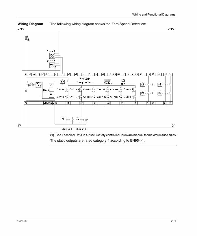
Wiring and Functional Diagrams
Wiring Diagram The following wiring diagram shows the Zero Speed Detection:
(1) See Technical Data in XPSMC safety controller Hardware manual for maximum fuse sizes.
The static outputs are rated category 4 according to EN954-1.
F1(1)
XPSMC16Safety ControllerT
A2 GNDGNDGND o1 o2 o3 o4 o5 o6 14 24 34 44
K3
K4
K1
K2
Channel 1
Channel 2
Channel 1
Channel 2
Channel 1
Channel 2
Channel 1
Channel 2
Channel 1
Channel 2
Channel 1
Channel 2
K0
µC 1
µC 1
LOGIC
24 V
5 V
0V
+24 V +24 V
A1 c8 c7 c6 c5 c4 c3 c2 c1 i1 i2 i3 i4 i5 i6 i7 i8 i9 i10 i11 i12 i13 i14 i15 i16 13 23 H1 33 34
TERFieldbus
K01 K02
0V
Channel 2
-
Channel 1
+-
+
A
A
Sensor 2
Sensor 1
33003281 201

Wiring and Functional Diagrams
Important Key Points to Observe
The following points should be observed for the correct operation of the zero speed detection:� The sensors must be arranged so that only 1 sensor is activated at any given time
(= HIGH-Signal).� If both sensors are in the LOW state, a cable break error message is indicated
and the corresponding outputs are deactivated.� If both sensors are in the HIGH state after power on of the XPSMC, a notification
is available via Modbus RTU, or via the configuration terminal (PC), and the corresponding outputs are deactivated. After a zero speed detection and a subsequent motion the notification is reset.
� If zero speed is already detected and both sensors are in HIGH state, a notification is available via Modbus RTU, or via the configuration terminal (PC), and the corresponding outputs are activated.
� If only 1 sensor produces a dynamic signal after a zero speed, an error message appears after 30 s and the corresponding outputs are deactivated.
� If, after the XPSMC has started, both sensors are in the LOW state, an error message is available via the Error LED on the XPSMC and Modbus RTU, or via the configuration terminal (PC).
Note: You cannot use the Zero Speed Detection device simultaneously with the Shift/Chain Break Monitoring device on the XPSMC safety controller, because there are only two counter inputs (i1 and i2) per controller.
Note: The output will be activated if the sensors detect no motion.
202 33003281

Wiring and Functional Diagrams
Sensor States and Behavior
Switch-on Sequence
Operation
* If the state of the sensors is inverse (0/1, 1/0), the behavior is identical.
** If the firmware version is earlier than 2.34 an error message (short circuit between inputs) appears instead of a notification. This error message must be acknowledged with the reset button.
Error Message External error messages must be acknowledged with the reset button.
Notification A notification, sent via Modbus, does not need to be acknowledged. As soon as the sensor states change, it will be acknowledged automatically.
State of Sensor 1 0 0 (*) 1
State of Sensor 2 0 1 (*) 1
Behavior Error Message Zero Speed Notification (**)
Output 0 1 0
State of Sensor 1 0 0 (*) 1
State of Sensor 2 0 1 (*) 1
Behavior Error Message Zero Speed Notification
Output 0 1 1
33003281 203

Wiring and Functional Diagrams
Injection Molding Machines
Functional Diagram
The following functional diagram shows the Safety Guard with One Channel with Start Interlock and different Start Functions:
Start Function Start Interlock = NO
Automatic Start
Monitored StartRising Edge
InputLimit switch 1
Guardclosed
Guardopened
Guardclosed
t < t syn.
Power ON
(RUN)
InputLimit switch 2
InputValve monitoring
Output
no start
InputLimit switch 1
Guardclosed
Guardopened
Guardclosed
t < t syn.
Power ON
(RUN)
InputLimit switch 2
InputValve monitoring
InputStart
no start
Output
204 33003281

Wiring and Functional Diagrams
Monitored StartFalling Edge
Start Function Start Interlock = NO
InputLimit switch 1
Guardclosed
Guardopened
Guardclosed
t < t syn.
Power ON
(RUN)
InputLimit switch 2
InputValve monitoring
Input Start
no start
Output
33003281 205

Wiring and Functional Diagrams
Wiring Diagram The following wiring diagram shows the Injection Molding with Start Functions:
EDM External Device MonitoringESC External Start Conditions(1) See Technical Data in XPSMC safety controller Hardware manual for maximum fuse sizes.
The static outputs are rated category 4 according to EN954-1.
F1(1)
Safety ControllerXPSMC16T
A2 GNDGNDGND o1 o2 o3 o4 o5 o6 14 24 34 44
K3
K4
K1
K2
Channel 1
Channel 2
Channel 1
Channel 2
Channel 1
Channel 2
Channel 1
Channel 2
Channel 1
Channel 2
Channel 1
Channel 2
K0
µC 1
µC 1
LOGIC
24 V
5 V
0V
+24 V +24 V
A1 c8 c7 c6 c5 c4 c3 c2 c1 i1 i2 i3 i4 i5 i6 i7 i8 i9 i10 i11 i12 i13 i14 i15 i16 13 23 H1 33 34
TERFieldbus
K01 K02
Channel 1 Channel 2
0V
ES
K01
K02
S1
Start
S2 S3
open
EDM
S4 =Monitoring of the second power cir-cuit cutoff device.
������������������������������������������������������������������������
S4
206 33003281

Wiring and Functional Diagrams
Hydraulic Press Valve Monitoring
Functional Diagram
The following functional diagram shows the Hydraulic Press Valve Monitoring:
Stopin OTS
Opening of PressStopin BDC
Closing of PressStop
in OTS
InputClosing of Press
InputOpening of Press
InputValve O+C
OutputClosing of Press
OutputOpening of Press
t < t syn.
t < t syn.
t < t syn.
InputValve C
InputValve O
Sensor signals at valve level:
Valve Stop(Opened)
Pressing(Closing)
Stop(Closed)
Retraction(Opening)
Valve C
Valve O
Valve O + C
Sensor
1
2
3
33003281 207

Wiring and Functional Diagrams
Wiring Diagram The following wiring diagram shows the Hydraulic Press Valve Monitoring:
(1) See Technical Data in XPSMC safety controller Hardware manual for maximum fuse sizes.
The static outputs are rated category 4 according to EN954-1.
F1(1)
XPSMC16Safety ControllerT
A2 GNDGNDGND o1 o2 o3 o4 o5 o6 14 24 34 44
K3
K4
K1
K2
Channel 1
Channel 2
Channel 1
Channel 2
Channel 1
Channel 2
Channel 1
Channel 2
Channel 1
Channel 2
Channel 1
Channel 2
K0
µC 1
µC 1
LOGIC
24 V
5 V
0V
+24 V +24 V
A1 c8 c7 c6 c5 c4 c3 c2 c1 i1 i2 i3 i4 i5 i6 i7 i8 i9 i10 i11 i12 i13 i14 i15 i16 13 23 H1 33 34
TERFieldbus
K01 K02
0V
Press Opening Enable
-
Press Closing Enable
S5
Openthe
Press
S4
Closethe
Press+-
+
+-
Sensor 3 - Valve O + C
Sensor 2 - Valve O
Sensor 1 - Valve C
A
A
A
Sensor 3
Sensor 2
Sensor 1
208 33003281

Wiring and Functional Diagrams
Hydraulic Press 2
Functional Diagrams
The following functional diagram shows the Hydraulic Press 2, Mode = INCHING
Mode AUTOMATIC
Emergency Stop
Mode INCHING
Mode SINGLE STORKE
OPENING COMMAND
SAFETY COMMAND
OTS
NWK*
UT
VALVE C*
VALVE O*
VALVE O+C*
OUTPUT OPENING
OUTPUT CLOSING
OVERTRAVEL OK
HYDRAULIC PUMP*
CLOSING COMMAND*
* = not used
Hyd
rau
lic P
ress
, Mo
de
= In
chin
g
33003281 209

Wiring and Functional Diagrams
The following functional diagram shows the Hydraulic Press 2, Mode = SINGLE STROKE, with overtravel monitoring and Open + Close command from the PLC:
Hyd
rau
lic P
ress
, Mo
de
= S
ING
LE
STO
RK
E, w
ith
ove
rtra
vel m
on
ito
rin
g a
nd
Op
en +
Clo
se
com
man
d f
rom
PL
C
Emergency Stop
Mode INCHING
Mode SINGLE STROKE
Mode AUTOMATIC
HYDRAULIC PUMP
OPENING COMMAND
CLOSING COMMAND
SAFETY COMMAND
OTS
NWK
UT
VALVE C
VALVE O
VALVE O+C
OUTPUT OPENING
OUTPUT CLOSING
OVERTRAVEL OK
210 33003281

Wiring and Functional Diagrams
The following functional diagram shows the Hydraulic Press 2, Mode = SINGLE STROKE:
Emergency Stop
Mode INCHING
Mode SINGLE STROKE
Mode AUTOMATIC
HYDRAULIC PUMP*
OPENING COMMAND*
CLOSING COMMAND*
SAFETY COMMAND
OTS
NWK*
UT*
VALVE C
VALVE O
VALVE O+C
OUTPUT OPENING
OUTPUT CLOSING
OVERTRAVEL OK*
* = not used
Hyd
rau
lic P
ress
, Mo
de
= S
ING
LE
ST
RO
KE
33003281 211

Wiring and Functional Diagrams
The following functional diagram shows the Hydraulic Press 2, Mode = Automatic, with overtravel monitoring and Open + Close command from the PLC:
Hyd
rau
lic P
ress
, Mo
de
= A
UT
OM
AT
IC, w
ith
ove
rtra
vel m
on
ito
rin
g a
nd
Op
en +
Clo
se c
om
-m
and
fro
m P
LC
Emergency Stop
Mode INCHING
Mode SINGLE STROKE
Mode AUTOMATIC
HYDRAULIC PUMP
OPENING COMMAND
CLOSING COMMAND
SAFETY COMMAND
OTS
NWK
UT
VALVE C
VALVE O
VALVE O+C
OUTPUT OPENING
OUTPUT CLOSING
OVERTRAVEL OK
212 33003281

Wiring and Functional Diagrams
The following functional diagram shows the Hydraulic Press 2, Mode = AUTOMATIC, without OT + UT signals:
Emergency Stop
Mode INCHING
Mode SINGLE STROKE
Mode AUTOMATIC
HYDRAULIC PUMP*
OPENING COMMAND
CLOSING COMMAND
SAFETY COMMAND
OTS*
NWK*
UT*
VALVE C
VALVE O
VALVE O+C
OUTPUT OPENING
OUTPUT CLOSING
OVERTRAVEL OK*
* = not used
Hyd
rau
lic P
ress
, Mo
de
= A
UT
OM
AT
IC, w
ith
ou
t O
T +
UT
sig
nal
s
33003281 213

Wiring and Functional Diagrams
Wiring Diagram The following wiring diagram shows the Hydraulic Press 2:
0 V
230 V AC
0 V
230 V AC
F1
Safety ControllerXPSMC32T
A1 c8 c7 c6 c5 c4 c3 c2 c1
A2 GNDGNDGND o1 o2 o3 o4 o5 o6 14 24 34 44
i1 i2 i3 i4 i5 i6 i7 i8 i9 i1 i11 i12 i13 i14 i1 i1 13 23 H1 33 34
K3
K4
K1
K2
Channel 1
Channel 2
Channel 1
Channel 2
Channel 1
Channel 2
Channel 1
Channel 2
Channel 1
Channel 2
Channel 1
Channel 2
TERK0
µC 1
µC 1
LOGIC
24 V
5 V
N N
i17 i1
KM1
KM1SM2
OFF
SM1
ON
FM1
2
1
E-Stop
+24 V +24 V
i1 i2 i2 i2 i2 i2 i2 i2 i2 i2 i2 i3 i3 i3
210 3
OTS = Top Dead CenterUT = Bottom Dead CenterNWK = Overtravel Monitoring
Y1
S8
Operation Modes+-
B1
F2
close
Y2
open
Y3
open+close
S7
Two-hand button 2
S6
Two-hand button 1
S5
Emergency Stop
KM1
Kx
S4
NWK
S3
UT
S2
OTSOpen Command
Close Command
S1
OPEN
Valve C
+-
B2
Valve O
+-
B3
Valve O+C
0 - Off1 - Inching2 - Single Stroke3 - Automatic
214 33003281

Wiring and Functional Diagrams
Eccentric Press
Functional Diagrams
The following functional diagram shows the Eccentric Press, Mode = SINGLE STROKE
Bra
king
Sin
gle
Str
oke
Off
EmergencyStop
OperationMode:
Inpu
t Pus
h B
utto
n 1
NO
Inpu
t Pus
h B
utto
n 1
NC
Inpu
t Pus
h B
utto
n 2
NO
Inpu
t Pus
h B
utto
n 2
NC
Inpu
t Em
erge
ncy
Sto
pC
hann
el 1
Inpu
t Em
erge
ncy
Sto
pC
hann
el 2
Inpu
tO
TS
Inpu
tU
NIn
put
PS
V 1
Inpu
tP
SV
2In
put
Con
tinuo
us O
ff
Inpu
tR
eset
Inpu
tM
ode
Sel
ecto
r S
witc
h O
ff
Inpu
tM
ode
Sel
ecto
r S
witc
h In
chin
gIn
put
Mod
e S
elec
tor
Sw
itch
Sin
gle
Str
oke
Inpu
tM
ode
Sel
ecto
r S
witc
hC
ontin
uous
Aut
omat
icO
utpu
tV
alve
1O
utpu
tV
alve
2
Out
put
Em
erge
ncy
Sto
p
Sto
p in
OT
S
Start
SINGLESTROKE
Clo
sing
of
Pre
ssS
top
in O
TS
t < 5
00m
s
max
. Ove
rtra
vel
Mai
ntai
n au
tom
. ru
n-up
t < t
syn.
t < t
syn.
Bra
king
33003281 215

Wiring and Functional Diagrams
The following functional diagram shows the Eccentric Press, Mode = INCHING
Eng
age
Dis
enga
geE
ngag
eD
isen
gage
Eng
age
Dis
enga
geS
top
OT
S
t < 5
00m
st <
500
ms
t < 5
00m
s
Inch
ing
Off
EmergencyStop
Reset SelectorSwitchInching
Inpu
t 2-H
and
Pus
h B
utto
n 1
NO
Inpu
t 2-H
and
Pus
h B
utto
n 1
NC
Inpu
t 2-H
and
Pus
h B
utto
n 2
NO
Inpu
t 2-H
and
Pus
h B
utto
n 2
NC
Inpu
t Em
erge
ncy
Sto
pC
hann
el 1
Inpu
t Em
erge
ncy
Sto
pC
hann
el 2
Inpu
tO
TS
Inpu
tU
NIn
put
PS
V 1
Inpu
tP
SV
2In
put
Con
tinuo
us O
ff
Inpu
tR
eset
Inpu
tM
ode
Sel
ecto
r S
witc
h O
ff
Inpu
tM
ode
Sel
ecto
r S
witc
h In
chin
gIn
put
Mod
e S
elec
tor
Sw
itch
Sin
gle
Str
oke
Inpu
tM
ode
Sel
ecto
r S
witc
hC
ontin
uous
Aut
omat
icO
utpu
tV
alve
1O
utpu
tV
alve
2
Out
put
Em
erge
ncy
Sto
p
Irre
leva
nt
216 33003281
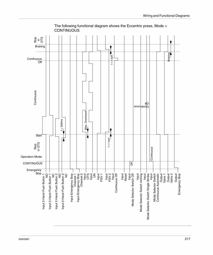
Wiring and Functional Diagrams
The following functional diagram shows the Eccentric press, Mode = CONTINUOUS
EmergencyStop
Operation Mode:
CONTINUOUS
Inpu
t 2-H
and
Pus
h B
utto
n 1
NO
Inpu
t 2-H
and
Pus
h B
utto
n 1
NC
Inpu
t 2-H
and
Pus
h B
utto
n 2
NO
Inpu
t 2-H
and
Pus
h B
utto
n 2
NC
Inpu
t Em
erge
ncy
Sto
pC
hann
el 1
Inpu
t Em
erge
ncy
Sto
pC
hann
el 2
Inpu
tO
TS
Inpu
tU
NIn
put
PS
V 1
Inpu
tP
SV
2In
put
Con
tinuo
us O
ff
Inpu
tR
eset
Inpu
tM
ode
Sel
ecto
r S
witc
h O
ff
Inpu
tM
ode
Sel
ecto
r S
witc
h In
chin
gIn
put
Mod
e S
elec
tor
Sw
itch
Sin
gle
Str
oke
Inpu
tM
ode
Sel
ecto
r S
witc
hC
ontin
uous
Aut
omat
icO
utpu
tV
alve
1O
utpu
tV
alve
2
Out
put
Em
erge
ncy
Sto
p
Start
ContinuousOff
Con
tinuo
usS
top
in O
TS
Sto
pin
O
TS
t < 5
00m
s
Max
. Ove
rtra
vel
t < t
syn.
t < t
syn.
Off
Con
tinuo
us
Bra
king
ContinuousOff
Braking
33003281 217

Wiring and Functional Diagrams
Wiring Diagram
The following wiring diagram shows the Eccentric Press:
OTS Top Dead CenterPSV Safety Valve(1) See Technical Data in XPSMC safety controller Hardware manual for maximum fuse sizes.
The static outputs are rated category 4 according to EN954-1.
HAZARDOUS VOLTAGE
Disconnect all power before servicing equipment.
Failure to follow these instructions will result in death or serious injury.
DANGER
Fieldbus
0 V
230 V ~
0 V
230 V ~
F1(1)
XPSMC16safety controllerT
A2 GNDGNDGND o1 o2 o3 o4 o5 o6 14 24 34 44
K3
K4
K1
K2
Channel 1
Channel 2
Channel 1
Channel 2
Channel 1
Channel 2
Channel 1
Channel 2
Channel 1
Channel 2
Channel 1
Channel 2
TERK0
µC 1
µC 1
LOGIC
24 V
5 V
N N
KM1
KM1SM2
On
SM1
Off
FM1
2
1
+24 V +24 V
210 3
Valve ControlPSV1
PSV1 PSV2
(Y1a)Y1
Valve ControlPSV2
(Y1b)
a bP
2
4
1P
2
4
1
S8
S7
RESET
S6
(Y1b)
PSV 2
1
P>
S5
UN
S4
OTS
S3S2S1
Main drive
A1 c8 c7 c6 c5 c4 c3 c2 c1 i1 i2 i3 i4 i5 i6 i7 i8 i9 i10 i11 i12 i13 i14 i15 i16 13 23 H1 33 34
2-Hand
Push
Button1
2-Hand
Push
Button2
Emer-
gency
11
12
21
22
(Y1a)
PSV1 2
1
P>
22
21
1
2
3
4
5
6
7
8
F2(1)
S9
Closed
tool
Closedtool
218 33003281

Wiring and Functional Diagrams
Eccentric Press 2
Functional Diagram
The following functional diagram shows the Eccentric Press 2, Mode = INCHING:
Emergency Stop
Mode INCHING
Mode SINGLE STROKE
Mode CONTINUOUS
Mode CONTINUOUS
AUTOMATIC
Safety Means + Start
SAFETY Means for Continuous
Automatic*
Shaft / Chain Break Sensor*
OTS*
UN*
PSV1*
PSV2*
CONTINUOUS OFF*
RESET
OUTPUT
* = Not Used
Ecc
entr
ic P
ress
: IN
CH
ING
33003281 219

Wiring and Functional Diagrams
The following functional diagram shows the Eccentric Press 2, Mode = SINGLE STROKE:
Emergency Stop
Mode INCHING
Mode SINGLE STROKE
Mode CONTINUOUS
Mode CONTINUOUS AUTO-
MATIC
Safety Means + Start
SAFETY Means for Continuous
Automatic*
Shaft / Chain Break Sensor*
OTS
UN
PSV1
PSV2
CONTINUOUS OFF*
RESET
OUTPUT
* = Not Used
Ecc
entr
ic P
ress
: S
ING
LE
ST
RO
KE
T < Tsync
T < Tsync
T < TTot
220 33003281

Wiring and Functional Diagrams
The following functional diagram shows the Eccentric Press 2, Mode = CONTINUOUS:
Emergency Stop
Mode INCHING
Mode SINGLE STROKE
Mode CONTINUOUS
Mode CONTINUOUS AUTO-
MATIC
Safety Means + Start
SAFETY Means for Continuous
Automatic*
Shaft / Chain Break Sensor
OTS
UN
PSV1
PSV2
CONTINUOUS OFF*
RESET
OUTPUT
* = Not Used
Ecc
entr
ic P
ress
: C
ON
TIN
UO
US
T < Tsync
T < Tsync
T < TTot
33003281 221

Wiring and Functional Diagrams
The following functional diagram shows the Eccentric Press 2, Mode = CONTINUOUS AUTOMATIC:
Emergency Stop
Mode INCHING
Mode SINGLE STROKE
Mode CONTINUOUS
Mode CONTINUOUS AUTO-
MATIC
Safety Means + Start
SAFETY Means for Continuous
Automatic
Shaft / Chain Break Sensor
OTS
UN
PSV1
PSV2
CONTINUOUS OFF
RESET
OUTPUT
* = Not Used
Ecc
entr
ic P
ress
: C
ON
TIN
UO
US
AU
TOM
AT
IC
T < Tsync
T < Tsync
T < TTot
222 33003281

Wiring and Functional Diagrams
Wiring Diagram
The following image shows the wiring diagram of the Eccentric Press 2 device:
OTS Top Dead Center PSV Safety Valve
HAZARDOUS VOLTAGE
Disconnect all power before servicing equipment.
Failure to follow these instructions will result in death or serious injury.
DANGER
0 V
230 V AC
0 V
230 V AC
F1
Safety ControllerXPSMC16T
A1 c8 c7 c6 c5 c4 c3 c2 c1
A2 GNDGNDGND o1 o2 o3 o4 o5 o6 14 24 34 44
i1 i2 i3 i4 i5 i6 i7 i8 i9 i1 i11 i12 i13 i14 i1 i1 13 23 H1 33 34
K3
K4
K1
K2
Channel 1
Channel 2
Channel 1
Channel 2
Channel 1
Channel 2
Channel 1
Channel 2
Channel 1
Channel 2
Channel 1
Channel 2
TERK0
µC 1
µC 1
LOGIC
24 V
5 V
N N
i17 i18
KM1
KM1SM2
OFF
SM1
ON
FM1
2
1
E-Stop
+24 V +24 V
i19 i20 i21 i22 i23 i24 i25 i26 i27 i28 i29 i30 i31 i32
210 3
Valve controlPSV1
PSV1 PSV2
(PSV = Safety valve)
(Y1a)Y1
Valve controlPSV2
(Y1b)
a bP
2
4
1P
2
4
1
S8
Mode Selector SwitchS7
RESET
S6
Endur..
OFF
(Y1b)
PSV2 2
1
P>
(Y1a)
PSV1 2
1
P>
S5
UN
S4
OTS
S3
Emer-
gency
stop
NCNOS2
2-Hand
push-
button 2
NCNOS1
2-Hand push-
button 1
S10
Safety-
gate 1
S9
Safety
gate 1
Cam
Control-
ler B1
+-
A
33003281 223

Wiring and Functional Diagrams
Selector Switch
Functional Diagram
The following image represents the functional diagram of the Selector Switch device:
The static outputs are rated category 4 according to EN954-1.
Input Position 1
Input Position 2
Input Position 3
Input Position 4
Input Position 5
Pos
ition
0
Pos
ition
1
Pos
ition
2
Pos
ition
3
Pos
ition
4
Pos
ition
5
224 33003281
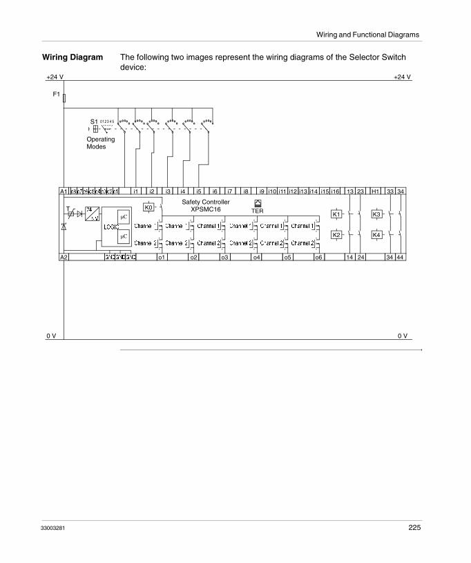
Wiring and Functional Diagrams
Wiring Diagram The following two images represent the wiring diagrams of the Selector Switch device:
0 V
+24 V
0 V
+24 V
F1
Safety ControllerXPSMC16T
A1 c8 c7 c6 c5 c4 c3c2 c1
A2 GNDGNDGND o1 o2 o3 o4 o5 o6 14 24 34 44
i1 i2 i3 i4 i5 i6 i7 i8 i9 i10 i11 i12 i13 i14 i15 i16 13 23 H1 33 34
K3
K4
K1
K2
Channel 1
Channel 2
Channel 1
Channel 2
Channel 1
Channel 2
Channel 1
Channel 2
Channel 1
Channel 2
Channel 1
Channel 2
TERK0
µC
µC
LOGIC
24
5 V
2 54310
Operating Modes
S1
33003281 225

Wiring and Functional Diagrams
Timer
Functional Diagram
The following image represents the functional diagram of the Timer device for the On-/Off-Delay:
Input
On-Delay
Pow
er O
N
Output
Timedelay
Input
Off-Delay
Pow
er O
N
Output
Time delay
226 33003281

Wiring and Functional Diagrams
The following image represents the functional diagram of the Timer device for the On-/Off Pulse:
Input
On Pulse
Pow
er O
N
Output
Pulse Time
Input
Off Pulse
Pow
er O
N
Output
Pulse Time
33003281 227

Wiring and Functional Diagrams
Wiring Diagram The following image represents the wiring diagram of the Timer device:
(1) See Technical Data in XPSMC safety controller Hardware manual for maximum fuse sizes.
The static outputs are rated category 4 according to EN954-1.
0 V 0 V
F1(1)
XPSMC16safety controllerT
A2 GNDGNDGND o1 o2 o3 o4 o5 o6 14 24 34 44
K3
K4
K1
K2
Channel 1
Channel 2
Channel 1
Channel 2
Channel 1
Channel 2
Channel 1
Channel 2
Channel 1
Channel 2
Channel 1
Channel 2
TERK0
µC 1
µC 1
LOGIC
24 V
5 V
+24 V +24 V
Control
signal
A1 c8 c7 c6 c5 c4 c3 c2 c1 i1 i2 i3 i4 i5 i6 i7 i8 i9 i1 i11 i12 i13 i14 i1 i1 13 23 H1 33 34
Output
signal
228 33003281
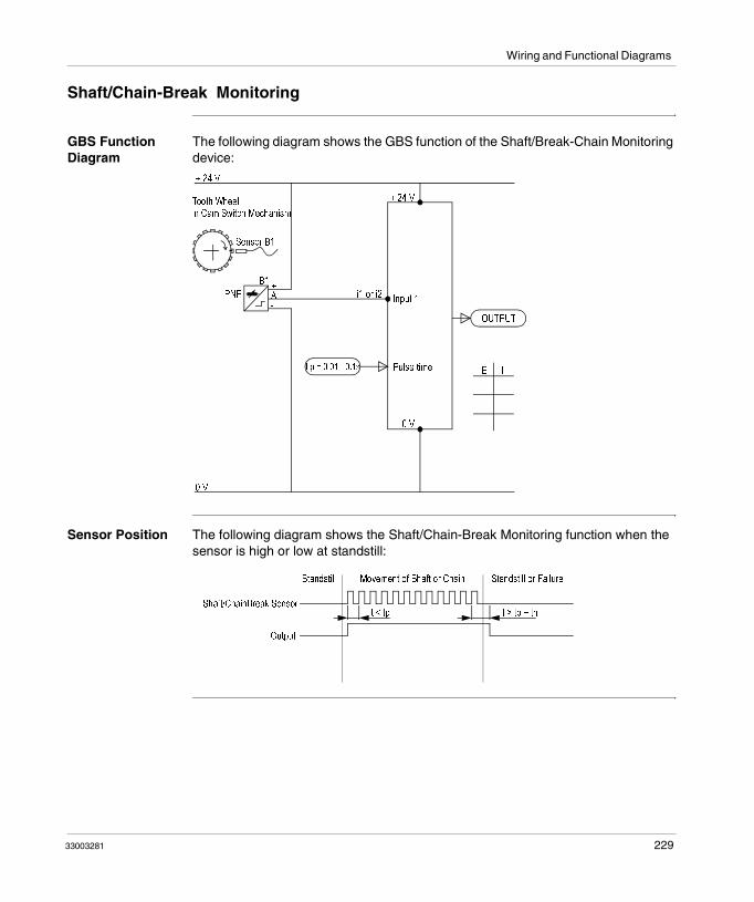
Wiring and Functional Diagrams
Shaft/Chain-Break Monitoring
GBS Function Diagram
The following diagram shows the GBS function of the Shaft/Break-Chain Monitoring device:
Sensor Position The following diagram shows the Shaft/Chain-Break Monitoring function when the sensor is high or low at standstill:
+ 24 V
Sensor B1
Tooth Wheelin Cam Switch Mechanism
B1
PNP-A+
Input 1i1 or i2
+ 24 V
Pulse timet p = 0.01 - 0.1s
0 V
OUTPUT
E I
- -
0 V
Shaft/ChainBreak Sensor
Output
Movement of Shaft or Chain Standstill or FailureStandstill
t < tp t > tp + th
33003281 229

Wiring and Functional Diagrams
Wiring Diagram The following image is the Shaft/Chain-Break Monitoring wiring diagram:
The static outputs are rated category 4 according to EN954-1.
0 V
+24 V
0 V
+24 V
Sensor at the Encoding Wheel in the Cam Controller
F1
+
Safety ControllerXPSMC16T
A1 c8 c7 c6 c5 c4 c3 c2 c1
A2 GNDGNDGND o1 o2 o3 o4 o5 o6 14 24 34 44
i1 i2 i3 i4 i5 i6 i7 i8 i9 i10 i11 i12 i13 i14 i15 i16 13 23 H1 33 34
K3
K4
K1
K2
Channel 1
Channel 2
Channel 1
Channel 2
Channel 1
Channel 2
Channel 1
Channel 2
Channel 1
Channel 2
Channel 1
Channel 2
TERK0
µC 1
µC 1
LOGIC
24 V
5 V
Only at i1 or i2.
A-
B1
230 33003281

Wiring and Functional Diagrams
Seat Valve Monitoring
Functional Diagram
The following image represents the functional diagram of the Seat Valve Monitoring device:
Power ON
(RUN) Start
Not ActivatedStart
ActivatedStart
Not Activated
InputStart
Output
InputValve Contact NO
t < t syn.
InputValve Contact NC
No Start
33003281 231

Wiring and Functional Diagrams
Wiring Diagram The following image represents the wiring diagram of the Seat Valve Monitoring device:
(1) See Technical Data in XPSMC safety controller Hardware manual for maximum fuse sizes.
The static outputs are rated category 4 according to EN954-1.
F1(1)
XPSMC16Safety ControllerT
A2 GNDGNDGND o1 o2 o3 o4 o5 o6 14 24 34 44
K3
K4
K1
K2
Channel 1
Channel 2
Channel 1
Channel 2
Channel 1
Channel 2
Channel 1
Channel 2
Channel 1
Channel 2
Channel 1
Channel 2
K0
µC 1
µC 1
LOGIC
24 V
5 V
0V
+24 V +24 V
A1 c8 c7 c6 c5 c4 c3 c2 c1 i1 i2 i3 i4 i5 i6 i7 i8 i9 i10 i11 i12 i13 i14 i15 i16 13 23 H1 33 34
TERFieldbus
Y1
0V
S1
Seat Valve
Seat
Valve
Operat-
ing Start
S2
Valve
contact
232 33003281

Wiring and Functional Diagrams
Enabling Device 2 Channel
Functional Diagram
The following diagram represents the functional diagram of the Enabling Device 2 Channel:
Position 1
Output
Position 0
InputEnable Switch NO
InputEnable Switch NC
Power ON
(RUN)
t < t Enable
Position 1
Position 1
Position 0
Position 2
No Start
33003281 233

Wiring and Functional Diagrams
Wiring Diagram The following diagram represents the wiring diagram of the Enabling Device 2 Channel:
(1) See Technical Data in XPSMC safety controller Hardware manual for maximum fuse sizes.
The static outputs are rated category 4 according to EN954-1.
F1(1)
XPSMC16Safety ControllerT
A2 GNDGNDGND o1 o2 o3 o4 o5 o6 14 24 34 44
K3
K4
K1
K2
Channel 1
Channel 2
Channel 1
Channel 2
Channel 1
Channel 2
Channel 1
Channel 2
Channel 1
Channel 2
Channel 1
Channel 2
K0
µC 1
µC 1
LOGIC
24 V
5 V
0V
+24 V +24 V
A1 c8 c7 c6 c5 c4 c3 c2 c1 i1 i2 i3 i4 i5 i6 i7 i8 i9 i10 i11 i12 i13 i14 i15 i16 13 23 H1 33 34
TERFieldbus
K01 K02
0V
Channel 2Channel 1
S4
Enabling Device 2 Channel Contact Function
NO 13 - 14
NC 21 - 22
0 21On
Off
13
14
NO21
22
NC
EnableSwitch
0 21 Legend
Note: XPSMC32 with 32 inputs i1...i32, otherwise identical.
234 33003281

Wiring and Functional Diagrams
Enabling Device 3 Channel
Functional Diagram
The following diagram represents the functional diagram of the 3-contact Enable Switch:
Position 1
InputEnable Switch NO
Output
No Start
InputEnable Switch NO
InputEnable Switch NC
Power ON
(RUN)
t < t Enable
Position 1Position 0 Position 2 Position 1 Position 0
33003281 235
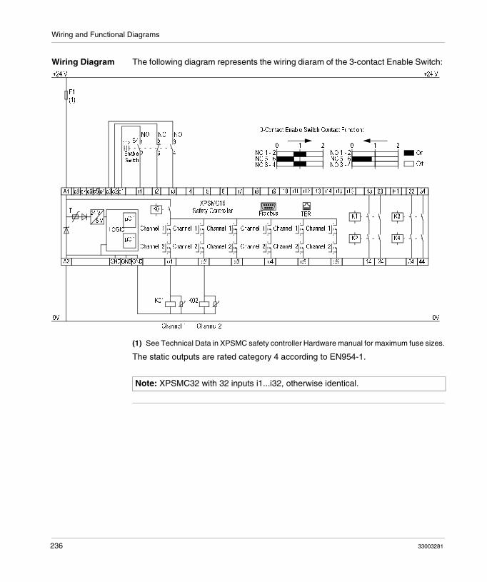
Wiring and Functional Diagrams
Wiring Diagram The following diagram represents the wiring diaram of the 3-contact Enable Switch:
(1) See Technical Data in XPSMC safety controller Hardware manual for maximum fuse sizes.
The static outputs are rated category 4 according to EN954-1.
F1(1)
XPSMC16Safety ControllerT
A2 GNDGNDGND o1 o2 o3 o4 o5 o6 14 24 34 44
K3
K4
K1
K2
Channel 1
Channel 2
Channel 1
Channel 2
Channel 1
Channel 2
Channel 1
Channel 2
Channel 1
Channel 2
Channel 1
Channel 2
K0
µC 1
µC 1
LOGIC
24 V
5 V
0V
+24 V +24 V
A1 c8 c7 c6 c5 c4 c3 c2 c1 i1 i2 i3 i4 i5 i6 i7 i8 i9 i10 i11 i12 i13 i14 i15 i16 13 23 H1 33 34
TERFieldbus
K01 K02
0V
Channel 2Channel 1
S4
3-Contact Enable Switch Contact Function:
NO 1 - 2
NO 3 - 4NC 5 - 6
0 21NO 1 - 2
NO 3 - 4NC 5 - 6
0 21On
Off
1
2
NO3
4
NO5
6
NC
Enable
Switch
0 21
Note: XPSMC32 with 32 inputs i1...i32, otherwise identical.
236 33003281

Wiring and Functional Diagrams
Foot Switch
Functional Diagram
The following images represents the Foot Switch functional diagram:
The static outputs are rated category 4 according to EN954-1.
Input NC
Volgage ON
(RUN) confirmed foot switch not confirmed confirmed
Input NO
Output
t < tsyn.
Input NC
Volgage ON
(RUN) confirmed foot switch not confirmed
Input NO
Output
t < tsyn.
confirmed foot switch
no switch on
Start interlock = NO
Start interlock = YES
33003281 237
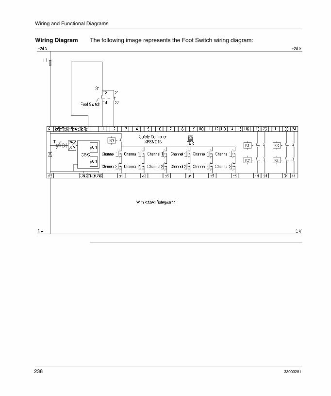
Wiring and Functional Diagrams
Wiring Diagram The following image represents the Foot Switch wiring diagram:
0 V
+24 V
0 V
+24 V
With Added Safeguards
F1
S1
Foot Switch
13
14
21
22
Safety ControllerXPSMC16T
A1 c8 c7 c6 c5 c4 c3 c2 c1
A2 GNDGNDGND o1 o2 o3 o4 o5 o6 14 24 34 44
i1 i2 i3 i4 i5 i6 i7 i8 i9 i10 i11 i12 i13 i14 i15 i16 13 23 H1 33 34
K3
K4
K1
K2
Channel 1
Channel 2
Channel 1
Channel 2
Channel 1
Channel 2
Channel 1
Channel 2
Channel 1
Channel 2
Channel 1
Channel 2
TERK0
µC 1
µC 1
LOGIC
24 V
5 V
238 33003281

Glossary
EDM external device monitoring
ESC external start conditions
ESPE electro sensible protective equipment
OSSD output safety switching device
OTS top dead center (Oberer Totpunktschalter)
RUN Mode XPSMC functional status during which the connected circuit members are monitored and the safety outputs are switched.
E
O
R
33003281 239

Glossary
Safety Input Monitored input for connection of switching devices. By using various control outputs (c1...c8) to power the safety inputs, cross-connections, external voltage and earth connections can be detected on the safety inputs.
Safety Outputs Relay or solid-state output activated by the XPSMC logic unit, which are able to cut off the subordinate control elements.
Synchronization Time
maximum time difference allowed between the appearance of 2 input signals
TER (Connector for Terminal)
8 pin RJ45 connector for the connections of a PC for the configuration or diagnostic (bus system with Modbus protocol) or connections of another Modbus module (PLC, terminals, etc. ...).
VDC validation counter
S
T
V
240 33003281

CBAIndex
Aapplication examples
3-contact Enable Switch, 235eccentric press, 215eccentric press 2, 219electrical diagram for XPSMC, 165Enabling Device 2 Channel, 233foot switch, 237hydraulic press 2, 209hydraulic press valve monitoring, 207injection molding machines, 204light curtain with relay outputs, 182light curtain with transistor outputs, 186magnetic switch, 192muting for light curtains type 4, 190One-Channel Emergency Stop, with automatic start, 167safety guard with one channel, 171safety mat, 198seat valve monitoring, 231timer, 226two channel safety guard, 174two channels safety guard with lock, 178Two-ChannelEmergency Stop, with start button, 169two-hand control, 196zero speed detection, 200
assigning the enabling device, 127assigning the protective guard function, 125assigning the starting function, 126assigning the switch position, 124
33003281
Cclosed tool, 112color definitions, 158configuration errors, 147connecting a device to a safety output, 49connection drawing
3-contact Enable Switch, 235eccentric press, 215eccentric press 2, 219electrical diagram for XPSMC, 165Enabling Device 2 Channel, 233foot switch, 237hydraulic press 2, 209hydraulic press valve monitoring, 207injection molding machines, 204light curtain with relay outputs, 182light curtain with transistor outputs, 186magnetic switch, 192muting for light curtains type 4, 190One-Channel Emergency Stop, with automatic start, 167safety guard with one channel, 171safety mat, 198seat valve monitoring, 231selector switch, 224shaft/chain-break monitoring, 229timer, 226two channel safety guard, 174two channels safety guard with lock, 178Two-ChannelEmergency Stop, with start
241

Index
button, 169two-hand control, 196zero speed detection, 200
copy/saving of a validated configuration, 152create a configuration, 34creating a new configuration, 120
Ddevice
closed tool, 112EDM, 97enabling, 100monitoring, 52OR, 106selector switch, 109start, 98timer, 104
diagnosticsXPSMC safety controller, 157
Eeccentric press, 84eccentric press 2, 88EDM adjustment, 128EDM device, 97emergency stop, 54, 132
Ffault diagnostics, 159foot switch control device, 107
Ggenerals, 117
Hhydraulic press 2, 80hydraulic press valve monitoring, 78
242
Iinjection molding machine, 76installation, 14installing the USB driver for the TSXCUSB485 cable, 13
Llight curtain
with muting, 60light curtains (ESPE) of category 4
without muting, 58loading, 149
Mmagnetic switch, 65master E-Stop device, 136maximum response time, 118menu command
check, 23controller, 24diagnostics, 29edit, 21file, 20help, 28mode, 22options, 27
modifying the properties, 50
OOR device, 106output states, 113overview of all control devices, 52
Ppassword, 139
Rread protocol from controller, 155response time, 34
33003281
Index
Ssafety guards, 55safety mat, 67safety output
assign a name, 129assign a stop category, 129copying the state of one onto another, 130
save, 137seat valve monitoring, 95select a controller type, 120selector switch device, 109sending a configuration, 141setting the safety outputs, 47shaft/chain break monitoring, 94shaft/chain break monitoring dialog settings, 94start device, 98system requirements, 12
Ttime
response time, 34timer, 104transfer of a validated configuration copy, 153two-channel or three-channel enabling device, 100two-hand control, 66
Uuser interface
elements of a window, 18window types, 16
Zzero speed detection, 69
33003281
243
Index
244
33003281