xmers facts & terminology
TRANSCRIPT

WELCOME

TRANSFORMERS
Facts/features/terminology
By K.R.Suri
Retd. General Manager,PGCIL
TOPICS FOR DISCUSSION
POWER Xmers Vs Distt. Xmers
Functions of Radiators/Cooling
Types of Xmers.
Capacity
Flux Density

TOPICS FOR DISCUSSIONCONTD.
Vector Group
Harmonics
%age Impedance
Parallel Operations.
OLTC
Protective equipments in Xmers.

POWER VS DISTRUBTION XMERS
No description available to distinguish.
However Xmers upto 10 MVA, 33/11 Kv are Distribution Xmers. Beyond that all are Power Xmers.
Available Power Xmers3 Phase,400Kv, 315/500 MVA1 Phase, 400kv, 105MVA1 Phase 765/800Kv, 500MVA

POWER VS DISTRUBTION XMERSCONTD.
Distribution Power
Designed for maximum Efficiency at around 75% of rated capacity
Designed for maximum Efficiency at full load at its rating.
Designed for low flux density i.e. 1- 1.2 Tesla. As they are subjected to low Voltage conditions.
Designed for high flux density i.e. up to 1.7 Tesla. As they are subjected to high voltages under light load conditions.
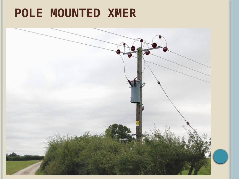
POLE MOUNTED XMER

33/11 KV XMER

400KV, 500 MVA XMER

1PHASE 765 KV XMER

1PHASE 765 KV XMER
FUNCTION OF RADIATORS OR COOLING
Radiators cool the Xmers indirectly through Xmer oil.
Xmer oil when gets heated up has a tendency to rise up and thus automatically circulates within the Xmers for cooling

RADIATOR COOLING PRINCIPLE
TRANSFORMERRadiator Bank
Heated oil Goes Up

TYPE OF COOLINGON – Oil and Natural.
ONAF – Oil natural Air Forced.
AFOF – Air forced Oil Forced.

OIL & NATURAL [ON] COOLING

FORCED AIR COOLING

FORCED AIR COOLING

OFAF COOLING
TRANSFORMER
Radiator Bank
Heated oil Goes Up
M

OIL PUMP

EFFECTS OF COOLING 500MVA – 400KV
Max. Temp. Rise Allowed 50˚ Above Ambient.
However while designing Techno - Economical Factors are considered.
ONAN ONAF OFAF
MVA 300 400 500
Current
433 578 725
TYPES BASED ON WINDINGS
2 Winding Xmers
3 Winding Xmers
Multi Winding Xmers
Auto Xmers

2 WINDING XMER

3 WINDING XMER

MULTI WINDING XMER

AUTO XMER

TYPES BASED ON OUTPUT PHASES
3 Phase to 3 Phase
3 Phase to 1 Phase
3 Phase to 2 Phase
3 Phase to Multi Phase

3PHASE TO SINGLE PHASE XMER.
127*1.732 = 230 V
127V
127V
127V
230 V
230 V
230 V

3 PHASE TO 2 PHASE XMER

SCOT/T CONNECTED XMERS.
120°
90°
BENEFITS OF MULTI CIRCUIT XMERS
Mostly incoming supply is unbalanced magnitude wise as well as vectorally.
Hence output voltage is regulated and gives balance loading to primary.

UNBALANCE LOADING

LIMITATIONS OF MULTI CIRCUIT XMERS
Not Rated so Far more than 10 MVA and high Voltages upto 33 KV.
TYPE OF XMER CONSTRUCTION WISE
Dry / Resign Bonded
Oil Type

DRY/RESIGN XMER

RATING WISE TYPESContinuous Rating
•POWER XMERS•DISTRIBUTION XMERS
Short time rated•TRACTIONS XMERS•ARC FURNACE XMERS•MINING XMERS

OTHER TYPES XMERS
High Impedance / Neutral Grounding.
Isolation
Special type Traction
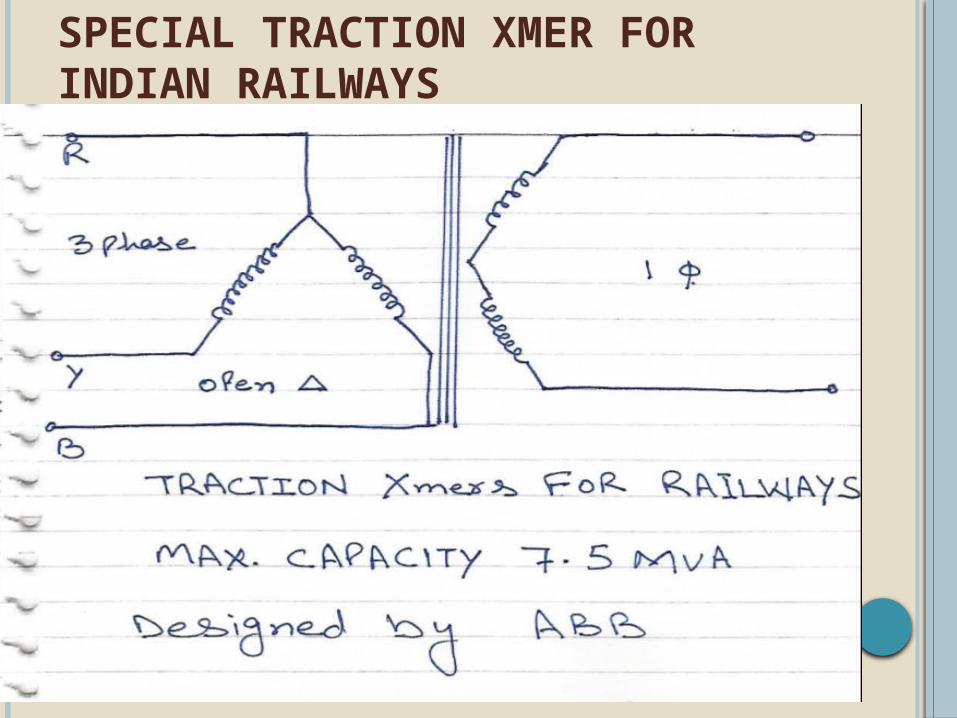
SPECIAL TRACTION XMER FOR INDIAN RAILWAYS

VECTOR GROUP
Δ ↔Υ ↔ ΥΔ ↔ Δ

VECTOR DIAGRAM
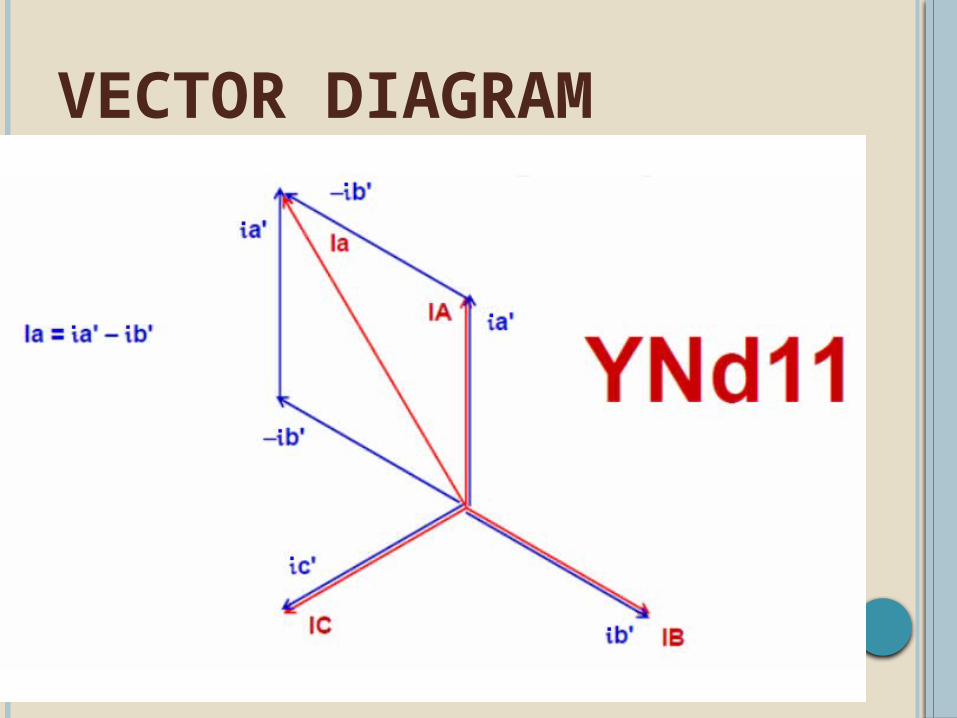
VECTOR DIAGRAM

TESTING FOR VECTOR GROUP

VECTOR GROUP OF AUTO XMERS

HARMONICSXmers of High Capacity beyond 250 MVA have tendency to generate 3rd harmonics.
3rd Harmonics -- ?

HARMONICS

HARMONICS

REASONS OF HARMONICS
Inherent design of Xmer
Developed due to characteristics of Load i.e. Induction Motors. CFL/Tube Lights, Neutral Unbalance, Quality of CRGO, Arc Furnaces
Out of Which third harmonic is more prominent.
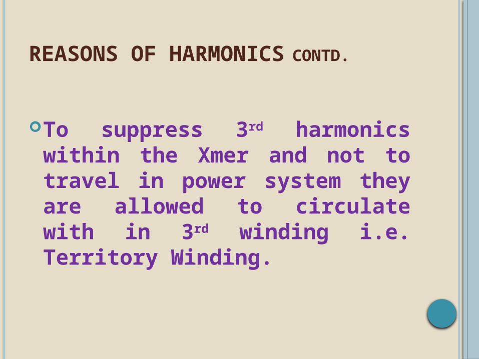
REASONS OF HARMONICSCONTD.
To suppress 3rd harmonics within the Xmer and not to travel in power system they are allowed to circulate with in 3rd winding i.e. Territory Winding.

TERRITORY WINDING R
YB
3rd Harmonics Circulates within Delta

CAPACITY
315 MVA 300+15*MVA500 MVA 470+30*MVA
* Rated for this capacity, However Not used.

TERRITORY WINDING - 1 PHASE

TERRITORY WINDING - 3 PHASE

%AGE IMPEDANCEIt is called as Voltage drop in transformer due to winding resistance and leakage reactance.
It is also called as voltage required on one side to calculate full load current under short circuit condition of other side.
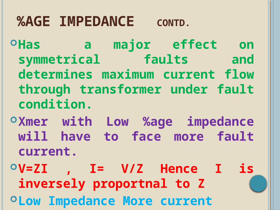
%AGE IMPEDANCECONTD.
Has a major effect on symmetrical faults and determines maximum current flow through transformer under fault condition.
Xmer with Low %age impedance will have to face more fault current.
V=ZI , I= V/Z Hence I is inversely proportnal to Z
Low Impedance More current

However High Impedance means increase voltage drop increases Xmer losses, Decreases Short Circuit Current, Big Size of Xmer
Which in other mean in techno - economical way
Normally Power Xmer are designed a range from 9% to 12%
Distribution Xmer are designed 5% to 8%
%AGE IMPEDANCE CONTD.

IMPEDANCE CHECK AT SITE

SIGNIFICANCE OF %AGE IMPEDANCE
It has a major role to Play in Parallel operation of Xmers.

WHY %AGE IMPEDANCE SHOULD BE SAME
Xmer having different %age Impedance i.e. Internal Drop will not share load in equal proportion.
Effective Impedance (Z) of Xmer is%age Impedance*V2/MVA

PARALLEL OPERATION OF XMERS
CB
T1 T2

CONDITIONS OF PARALLEL OPERATION
Voltage & Ratio should be same
Vector Group / Phase Sequence
should be same.
%age impedance should be same.
Tap Changer Ratio should be same.

XMERS HAVING DIFFERENT IMPEDANCE/CAPACITY
Xmer %age Imp. Capacity Voltage Effective Imp
A 12.5 315 400 63.5 Ohm
B 10.5 315 400 53.35 Ohm
C 12.5 500 400 40 Ohm

CASE I --- EQUAL %AGE IMPEDANCEASSUMING TOTAL LOAD 800 MVA
63.5Ohm
63.5Ohm
40 Ohm, 500 MVA
315 MVA
220 Kv
400 KV
223 MVA
223 MVA 354
MVA
I = 800*1000/400*1.73=1155 A
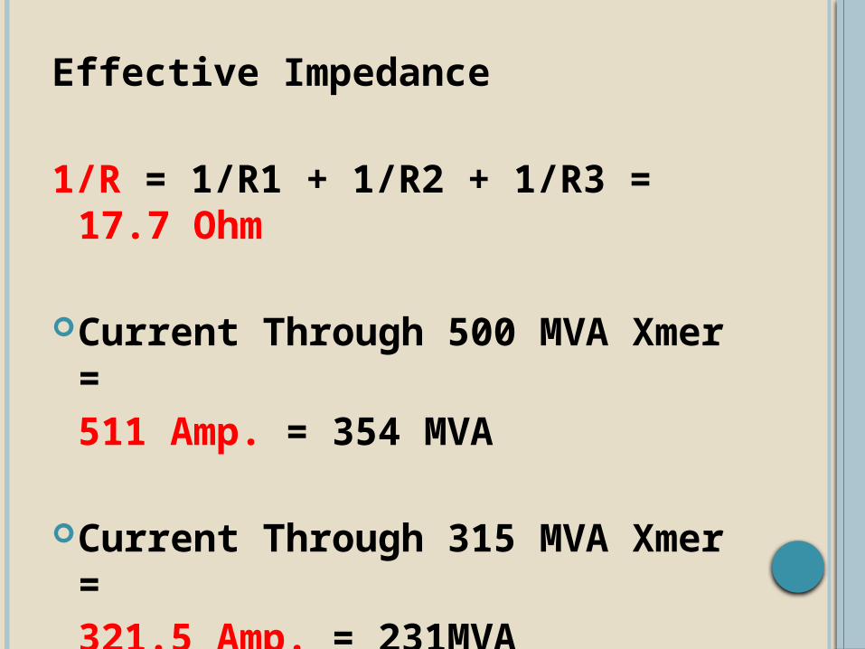
Effective Impedance
1/R = 1/R1 + 1/R2 + 1/R3 = 17.7 Ohm
Current Through 500 MVA Xmer = 511 Amp. = 354 MVA
Current Through 315 MVA Xmer = 321.5 Amp. = 231MVA
Total load 816 MVA
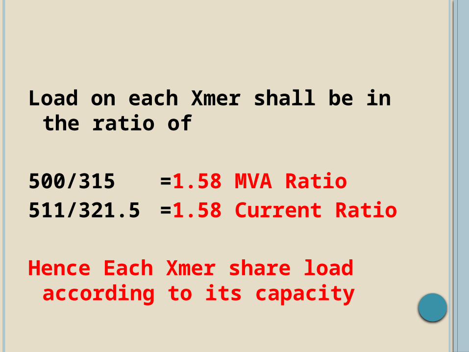
Load on each Xmer shall be in the ratio of
500/315 =1.58 MVA Ratio511/321.5 =1.58 Current Ratio
Hence Each Xmer share load according to its capacity

CASE II – UNEQUAL %AGE IMPEDANCEASSUMING TOTAL LOAD 800 MVA
63.5Ohm 63.5
Ohm
315 MVA
220 Kv
400 KV
251 MVA
251 MVA
290 MVA
I = 800*1000/400*1.73=1155 A
315 MVA
53.3Ohm
500 MVA

Effective Impedance1/R = 1/R1 + 1/R2 + 1/R3 = 19.90 Ohm.
Current Through 500 MVA Xmer = 431 Amp. = 298 MVA
Current Through 315 MVA Xmer =
361 Amp. = 251MVATotal load 800 MVA

Load ratio on each Xmer is
500/315 = 1.58 MVA Ratio431/361 = 1.19 Current Ratio
Hence Each Xmer is not sharing load according to its capacity.
CONCLUSION
600 MVA = X+X*1.19600 MVA = 2.19*XX = 274 MVA600 = 274+1.19*326Hence Load can only be allowed between 550 to 600MVA.

TAP CHANGERS
Types
Off Load
On Load

OFF LOAD TAP CHANGER

ON LOAD TAP CHANGERS
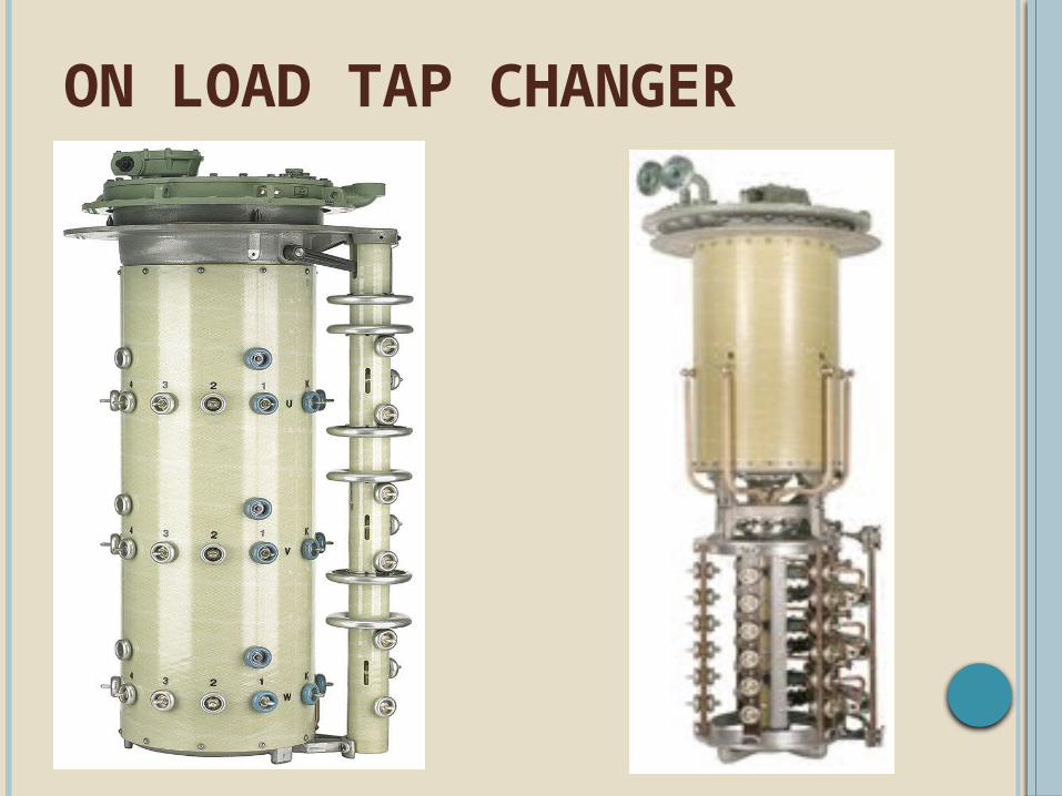
ON LOAD TAP CHANGER

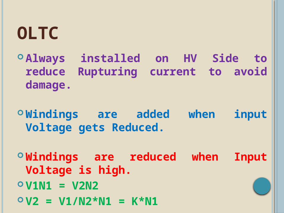
OLTCAlways installed on HV Side to reduce
Rupturing current to avoid damage.
Windings are added when input Voltage gets Reduced.
Windings are reduced when Input Voltage is high.
V1N1 = V2N2V2 = V1/N2*N1 = K*N1

TRANSFORMER OIL
TYPES
NAPTHELENE BASE
PARAFFIN BASE

NAPTHA BASE
EASILY OXIDISED------ HENCE SLUDGE FORMATION IS MORE. SLUDGE CIRCULATES WITH OIL AND DOES NOT HINDER COOLING
PARAFFIN BASE
SLOW OXIDATION RATE, IT IS INSOLUBLE THUS RESTS AT BOTTOM OF TANK & EFFECTS COOLING
INDIAN CONTEXT ---- PARAFFIN IS USED, AS EASILY AVAILABLE

PROTECTIVE EQUIPMENTS Buchhloz Relay
PRV
MOG
Silica Gel Breather
Fire Fighting SystemWater Spray SystemNitrogen Fire Extinguish System.
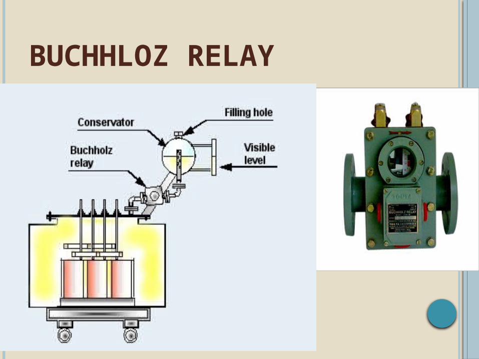
BUCHHLOZ RELAY

PRV
Transformer

MOG

SILICA GEL BREATHER
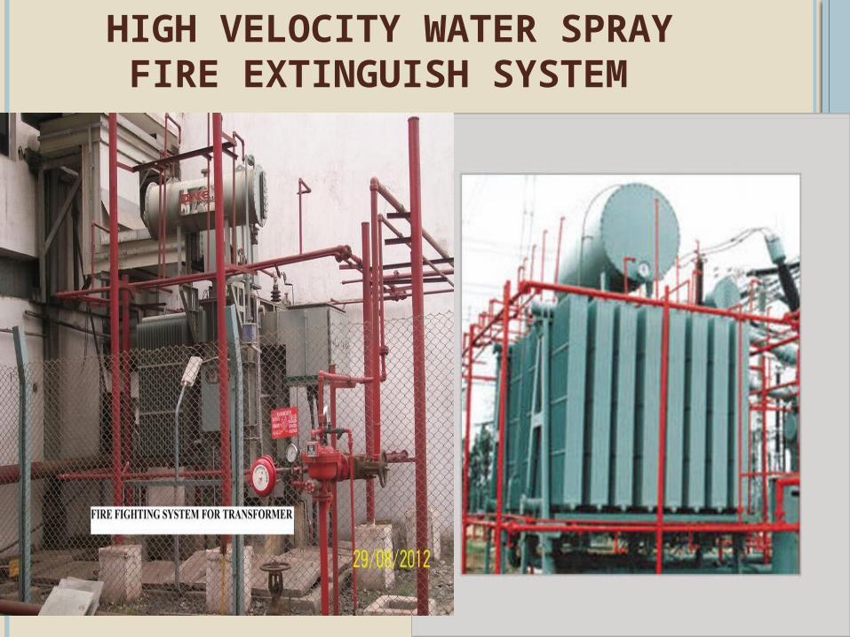
HIGH VELOCITY WATER SPRAY FIRE EXTINGUISH SYSTEM

TEMP. SENSORS
Sensors

NITROGEN FIRE EXTINGUISH SYSTEM

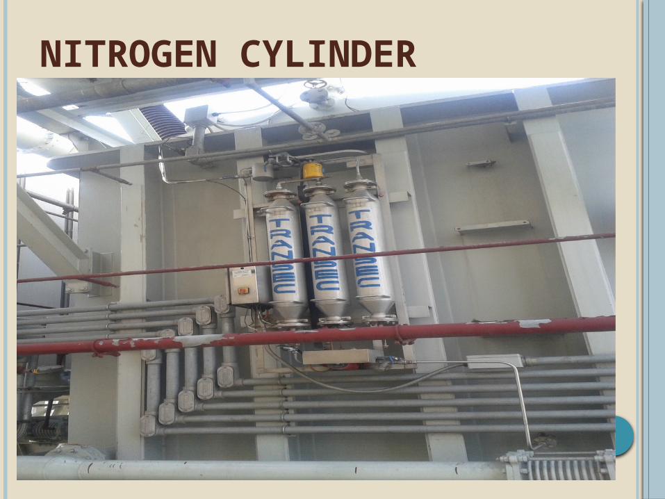
NITROGEN CYLINDER

Thank you