xld series power unit installation ... - gre alpha 200 installation guid… · gre alpha...
TRANSCRIPT
Gre Alpha Electronics Limited, Address: Unit 501, 5/F,No. 16 Science Park West Avenue, Hong Kong Science Park,Shatin,Hong Kong.
Tel: (852) 2423-3332 Fax: (852) 2423-3626
Website: www.grealpha.com
XLD Series Power Unit Installation Instructions
1) Installation of the XLD series power unit requires the proper connection of both the AC wiresto the AC facility power, and the DC wires to the LED lighting system. (Note: All electricalwiring should comply with local and national electrical codes. Installation should beperformed by qualified electrical service personnel. )
2) To access both the AC and DC power wiring and wiring compartments, remove the top coverby removing the 4 screws using a Philips screwdriver. Ensure that the white plastic washerson each screw are not lost during removal.
3) Install and secure the AC conduit pipe to the XLD power unit’s ½ “ knockout by using the proper conduit fitting hardware. The AC source wires should be protruding from the conduitpipe and into the XLD’s AC wiring compartment.(Note: For installation in outdoor or wet locations, liquid tight fittings and conduit mustbe used for proper NEMA 3 protection.)
4) Connect the AC source wires to the XLD power unit’s AC input wires using the proper ULapproved wire nuts. Refer to the rating label affixed on the XLD power unit for AC wire color codes. The Black wire from the XLD unit should connect to the incoming AC Linewire. The White wire from the XLD unit should connect to the incoming AC Neutral wire.Finally, the Green wire from the XLD unit should connect to the incoming AC Ground wire.(Note: The XLD’s complete metal case is referenced to AC ground, upon proper installation of AC input wires.)
5) Connect the XLD unit DC wires to the LED lighting system by connecting the DC wires tothe LED lighting system input wires. The wire connections are made within the XLD’s DC wiring compartment, using wire nuts, crimp terminals, wire-to-wire connectors, or any othertype of electrical connection. Refer to the rating label affixed on the XLD power unit for DCwire color codes. The Black wires from the XLD unit are the DC negative side and should connect to the lighting system’s DC negative input, ‘-‘. The Red wires from the XLD unit arethe DC positive side and should connect to the lighting system’s DC positive input, ‘+’. TheLED lighting system DC input wires can be secured to the XLD power unit, by attachingconduit pipe and conduit fittings, or cord and cord fittings onto the XLD’s DC side ½”knockout . Note: The output wires for each channel should not be interconnected.
6) Once all wiring is completed, turn on the AC supply to check for proper LED lighting systemoperation. Once proper operation is confirmed, turn off the AC supply and then re-install thetop cover of the XLD power unit, using the 4 screws and Philips screwdriver. Ensure that theplastic washers are installed on each screw before re-installation. It is also important toensure that all wiring is maintained within each wiring compartment to prevent wires frombeing pinched between the cover’s gasket and the unit’s case. (Note: In outdoorinstallations, or any installation in wet locations, tighten the screws using a torquecontrolled screwdriver, with a torque setting of 4.0 to 6.0 inch pounds.)
1 of 4
Product Application Note AN-008 Rev.A.0 Updated:13/05/30

Note: Heyco Liquid Tight Conduit and conduit fittings (or equivalent) required for installations requiring NEMA 3 protection. The DC Output side can also be used with liquid tight cord fittings and UL rated Cord.
XLD Series
LED Lighting System
Class 2 Power Supply w/ NEMA 3 protection
½” Conduit directly connected to power supply (EMT or Liquid Tight type)
120/240 VAC Supply From Facility
AC Input:Conduit ready input connection for ½” conduit and �ttings
DC Output:½” Conduit or Cord connection to LED System
Automatic Constant- voltage orconstant - current operation.
Typical Installation
DC Out: +V: Red Wires DC Gnd: Black Wires
+V1 DC
L N G
XLD200
AC In: Line – Black Wire Neutral – White Wire Ground – Green Wire
Connection Information
Gnd
Gre Alpha Electronics Limited, Address: Unit 501, 5/F,No. 16 Science Park West Avenue, Hong Kong Science Park,Shatin,Hong Kong.
Tel: (852) 2423-3332 Fax: (852) 2423-3626
Website: www.grealpha.com
2 of 4
Product Application Note AN-008 Rev.A.0 Updated:13/05/30
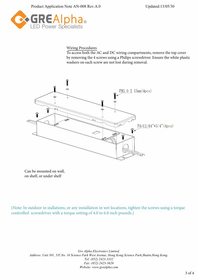
Wiring ProceduresTo access both the AC and DC wiring compartments, remove the top cover by removing the 4 screws using a Philips screwdriver. Ensure the white plastic washers on each screw are not lost during removal.
Can be mounted on wall, on shelf, or under shelf
(Note: In outdoor in stallations, or any installation in wet locations, tighten the screws using a torque controlled screwdriver with a torque setting of 4.0 to 6.0 inch pounds.)
3 of 4
Gre Alpha Electronics Limited, Address: Unit 501, 5/F,No. 16 Science Park West Avenue, Hong Kong Science Park,Shatin,Hong Kong.
Tel: (852) 2423-3332 Fax: (852) 2423-3626
Website: www.grealpha.com
Product Application Note AN-008 Rev.A.0 Updated:13/05/30

Note: All Installations must conform to UL, Local and National Electrical Codes.For NEMA 3 protection in outdoor installations, the use of Heyco liquid tight fittings (or equivalent) is required.
XLD Series LED Driver Optional Installation
AC Cord Input and DC Cord Output
UL Outdoor Rated AC Cord-Customer Supplied
Heyco Liquid Tight (or equivalent) Cord Fittings-Customer Supplied
XLDXXX-XXXX-FC
4 of 4
Product Application Note AN-007 Rev.A.0 Updated:13/05/30
Gre Alpha Electronics Limited, Address: Unit 501, 5/F,No. 16 Science Park West Avenue, Hong Kong Science Park,Shatin,Hong Kong.
Tel: (852) 2423-3332 Fax: (852) 2423-3626
Website: www.grealpha.com