xiv nasas: fatigue, fracture and ageing structures; eds ... · xiv nasas: fatigue, fracture and...
TRANSCRIPT
XIV NASAS: Fatigue, Fracture and Ageing Structures; Eds.: C M Manjunatha. VR Ranganath, RK Paretkar and DR Peshwe, 30-3 1 Januav 2005, Visvesvaraya National Institute of Technology, Nagpur, pp. 3 16-323.
Application of Acoustic Emission to Study Debond Growth in Co-eured/Co-bonded Composite Structures under Fatigue Loading
S Sanjeev ~ u m a r * , B Rarnanaiah, HN Sudheendra, GM Kamath and M Subba Rao Advanced Composites Division, National Aerospace Laboratories, Bangalore - 560 017
Abstract
Increasing use offibre-reinforced composite materials for primary and secondav components in aircrafi construction Izas resulted in the development of lightweight and eficient structures. The major emphasis is now towards realization of such structures at reduced cost. In order to achieve this, newer concepts in design and manufacturing of structural composites are being explored. One such concept is to make components with integral construction through co- curing and co-bonding. Through this approach, one can integrate a number of sub-components to realize assemblies in a single cure. Adhesive bonding is one of the most widely used processes for joining tcvo structural members. Adhesive bonding is preferred to mechanical fastening in view of the better structuml stifiess that can be achieved. However, the quality of bonding depends on a number of parameters and is very sensitive to the quality of the bonding supjfaces. Pn view of this, it may be extremely dl.cult arzd impractical to expect the same degree of bond quality over the bor~ded region, especially witlz large aircraft structzlral componetzts. Hence, we invariably end up with variations irz the bond quality. There is a concern from the designers as well as rhe certibing agerzcies with regard to these bond quality vuriations on its long-tenz structural pe$ormarzce. With this background, Advanced Composites Division, NAL, has projected a test programme to understand how the structure with inherent good bonds, poor bonds arzd debonds would behave and to what extent the presence of defects would reflect on the structural integrity. It is essential that the growth ofdebonds, debond initiation at poorly bonded regions are monitored in real-time to assess the structural integrity. Among the conventional Non-destructive Evaluation (NDE) techniques, Acoustic Emission (AE) is probably the only technique that would provide this information. In this paper, we describe the application of AE technique to monitor defect initiation and growth of debonds during fatigue cycling in co-cured/co-bonded structural components such as flaps for a civilian aircraft. This provides usejidl information towards establishing damage tolerance of a co-cureaco-bonded composite structure.
Keywords: Bonded Composite Joints, Debonds, Non-Destructive Evaluation (NDE), Acoustic Emission (AE), Structural Integrity, Fatigue Cycling.
1. Introduction
Development in composite materials technology has been responsible for the efforts to widen composite applications in order to enhance the performance of military and commercial aircrafts. The application of composites has evolved from secondary to primary structures with the growing knowledge and understanding of composites. The use of composites to form complex aerospace structural components in place of their metallic counterparts not only reduces the number of parts to make a component, but also reduces the use of fasteners and joints. Hence the advantage is two-fold: avoiding weak points like drilled holes for fasteners and joints in a component and fewer fasteners and joints mean shorter assembly time. As no drilling and machining operations are required, stress concentration is also avoided. The advent of co-curing and co-bonding techniques for the fabrication of composite structures is a quantum change in manufacturing and has indeed brought with it a whole lot of advantages. Water
* Corresponding author. Tel: 091-80-25086424; Fax: 091-80-21267352, E-mail: [email protected]
Sanjeev Kumar et al.
intrusion and galvanic corrosion between fasteners and composite are also critical issues associated with metallic fastening which can be overcome through co-curing/co-bonding.
1.1. Defects in Adhesive Bonds
Adhesive bonding of composite structures is surely the best alternative to mechanical fastening as it has the potential to save significant weight and costs. The stresses on a structure can be distributed over the entire bond area which eliminates stress concentration. The use of adhesive bonding has for long been' evaded due to the lack of confidence in the ability to control process variables to the extent needed. Efforts to quantify the effect of defects and process variability in improving reliability and producibility of bonded composite joints have been met with limited success. With increasing applications of adhesive bonding in the aerospace industry, more concerns arise towards Non-destructive Testing and Evaluation of these bonds and their properties. Evaluation of adhesive bonds to determine the strength of the joint is a critical need in realizing bonded primary structures. However, the evaluation of bond strength is considered the most difficult problem for Non-destructive evaluation and has always remained speculative. Although significant progress has been made on a variety of techniques to increase sensitivity of Non-destructive Evaluation (NDE) methods to detect bond line defects, no known Non- destructive technique has the ability to provide a measure of the bond strength. Load transfer in adhesive-bonded joints is primarily through shear, but peel stresses may also occur at some joints due to eccentricities in the load path [l]. The inherent weakness of bonded joints in peel strength makes them more vulnerable in the presence of bond line defects. Much care and attention must be paid to the preparation of adherend surfaces to realize a quality bond. Defects in bonded constructions may occur due to lack of proper preparation of adherend surfaces, presence of loose surface dirt and oil, variations in process parameters, insufficient pressure application for compaction during curing, moisture ingress etc. Composite structures undergo gradual degradation during their lifetime resulting in the initiation of different forms of damage. Monitoring for structural and functional failure is a major maintenance activity encountered during the service life of an aircraft. Every structure has an inherent requirement to function to its designed need and maintain its structural integrity throughout its service life. It is therefore understood that effective reliable techniques are essential for monitoring the health of aircraft structures. Although initial damage can occur at an early stage of use, composite structures can be used much longer in a safe way. For a correct assessment of the lifetime of a structure, continuous monitoring of its structural integrity is required.
1.2. Non-destructive Evaluation (NDE)
Quality Assurance of composite aircraft structures is mainly based on regular visual inspections and supplemented with techniques such as Ultrasonic and Radiography inspection. Besides these, there is still the possibility of occurrence of damage in between two inspection intervals. Hence, there is a wide interest in techniques that can continuously monitor the structural integrity of a composite structure in keal-time during its service life. A further advantage of this would be to estimate the remaining lifetime of the structure. Designers therefore aim at a damage-tolerant approach, which concerns with ensuring that defects that are assumed to be present from the start of a component's life will be found and appropriate action taken before they cause structural failure. This radical change in design principles from a safe-life approach towards damage-tolerance allows for lighter structures and better performance. Of all the NDE techniques available today, Acoustic Emission (AE) is probably the only technique that can be reliably used for real-time monitoring of aircraft structures to provide information about damage initiation and its propagation. Other NDE techniques such as Ultrasonic, Eddy current and Radiography are active methods that require direct energy input into the structure to detect the presence of flaws within it. In addition, these techniques need
Acousric emission for debotzcl gru~ath.. ...
access to the whole structure and therefore, the structure needs to be disassembled before inspection. AE being a passive NDE technique offers the capability of detecting active flaws within a structure in-situ. Such real-time monitoring of samctusal damage is possible with AE, which no other conventional NDE technique can.
1.3. Acoustic Emission Technique
Acoustic Emission (AE) is the phenomenon of generation of transient elastic waves due to rapid release of strain energy caused by structural alterations within a material. AE uses stress as a stimulus for flaws in a material to generate acoustic emissions. The stresses that are setup in the material cause the imperfections to grow and ultimately result in the failure of the structure. This gives AE the capability to predict and guard against failure and for directly assessing the structural integrity [29.
AE signals can be classified as a) Continuous, and b) Burst type based on the repetition rate of the activity that is generated within the material. Successive bursts of activity causes superposition, giving the appearance of continuous emission, although both are generated by discrete processes [3] .
Control surfaces of aircrafts are typically subjected to varying air loads during flight. These structures are designed to perform to their expected levels even if they are structurally undermined by flaws within them & externally. Therefore, rigorous testing of these structures is mandatory to qualify them for flight by subjecting them to static testing which typically comprises of various load cases. AE has been used to a large extent to characterize various failure modes in composites such as matrix cracking, fiberlmatrix debonding, delarninations and fiber pullout. Significant work has been carried out in identifying the type of damage mechanism in composites by the analysis and comparison of AE signal parameters, which is also known as "Signature Analysis". Each failure mode exhibits its own characteristic data pattern, which is very usefuI in directly identifying the kind of damage that has occurred in a structure and its criticality.
The objective of carrying out AE monitoring on the outboard flap during the course of fatigue cycling was to study the nature of debond growth and its effect on structural integrity. Debonds in the Flap were seen naturally occurring at the skin-stiffener interface after post curing. The presence of such debonds at the adhesive bond-lines is a cause of concern as it may compromise its structural integrity. This approach of real-time monitoring was to provide an early warning of damage growth, reliable qualitative assessment of structural integrity and also an insight into the typical AE characteristics of debond growth in bonded composite joints. Hence, the foremost requirement was to sense the debond growth that occurred if any at the rib locations. Analyzing the signal parameters would provide useful information on the behaviour of a co-bonded composite structure with a process induced defect when subjected to repeated cycles of loading.
2. Composite Control Surface (Flap) of SARAS Aircraft
The geometry of the carbon composite Outboard flap is shown in Fig. 1. The structure is fabricated through co-bonding of pre-cured skins and green stage ribs. The structure comprises of an aft box, an internal front spar and the nose skins. The aft box consists of the top and bottom skins, eight I-section ribs and the trailing edge block. Through co-bonding, the pre- cured top and bottom skins are bonded to the rib flanges using Redux-319 film adhesive.
At the trailing edge, the pre-cured trailing edge block is also bonded to the skins through Redux-319. This secondary bonding of the aft box ensures that all the eight ribs, the two pre- cured skins and the trailing edge block result in one stiffened integral structure. At the leading edge, the nose skins are riveted to the front spar. In such constructions, junctions at the rib flange & skins are most crucial and the probability of defect initiation at these regions is quite
Sa~ljeev Kumar et al.
high. Hence, it is preferable that the structural integrity is monitored at these regions during structural qualification tests to identify the occurrence of any premature failure.
Fig. 1. CAD model of outboard flap (top skin removed to show details inside).
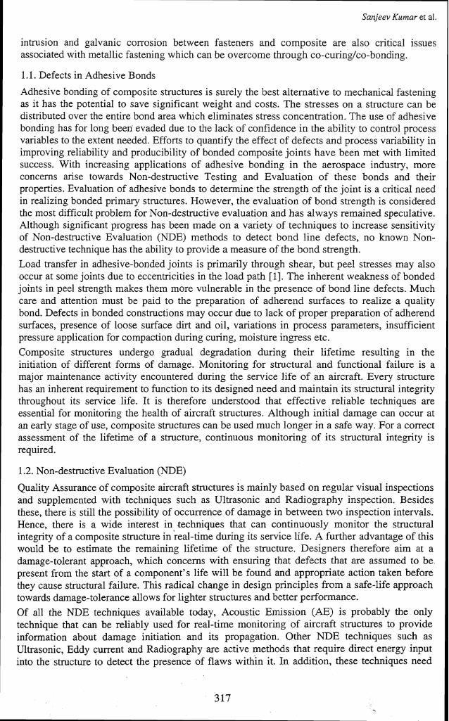
3. Experimental Setup A 20 channel AE system (MISTRAS 2001) from Physical Acoustics Corporation was used to monitor the AE activity during fatigue cycling of the composite control surface. Resonant (R15D) piezoelectric sensors with a frequency range of 100-1000 KHz were used. External preamplifiers were used to connect the sensors to the equipment. A total of eighteen sensors were mounted on the top side of the control surface whose locations are as shown in Fig. 2. This would cover all the rib locations to monitor debonds in the structure.
J
FIG:2 RE LOCATIONS ON OUTBOARD FLnP
Fig. 2. Acoustic emission sensor locations.
4. Structural Testing of Outboard Flap
It is mandatory from the certifying agencies that all control surfaces of an aircraft have to be subjected to static load testing unto limit load and Ultimate loads to qualify for flight. Limit load regime is the maximum load sustained by the structure during normal operations. The Ultimate load case was 1.98 times the limit load, taking all safety factors into consideration. The static ultimate load test up to 198% of Limit load was conducted on the structure. During testing, the structure withstood the ultimate load successfully without any failure. NDE carried out after the test showed no new flaws in the structure. Also, no growth in the existing debonds at the skin-rib interfaces were detected. The inference that was drawn from the test is that the structure is safe for one static cycle of loading with debonds present in it. If it can be assumed
Acoustic emission for debond growtlz.. ...
that one static cycle of loading is equivalent to one flight of the aircraft, it can be concluded that the flap can complete one flight safely. But an important question that arose after the static testing was, how would the debonds behave when the structure is subjected to multiple load cycles and at what stage of the cyclic loading do they start growing and how fast? To answer these, the flap was subjected to fatigue cycling.
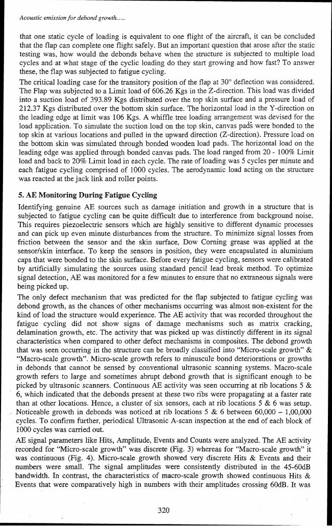
The critical loading case for the transitory position of the flap at 30" deflection was considered. The Flap was subjected to a Limit load of 606.26 Kgs in the Z-direction. This load was divided into a suction load of 393.89 Kgs distributed over the top skin surface and a pressure load of 212.37 Kgs distributed over the bottom skin surface. The horizontal load in the Y-direction on the leading edge at limit was 106 Kgs. A whiffle tree loading arrangement was devised for the load application. To simulate the suction load on the top skin, canvas pads were bonded to the top skin at various locations and pulled in the upward direction (2-direction). Pressure load on the bottom skin was simulated through bonded wooden load pads. The horizontal load on the leading edge was applied through bonded canvas pads. The load ranged from 20 - 100% Limit load and back to 20% Limit load in each cycle. The rate of loading was 5 cycles per minute and each fatigue cycling comprised of 1000 cycles. The aerodynamic load acting on the structure was reacted at the jack link and roller points.
5. AE Monitoring During Fatigue Cycling
Identifying genuine AE sources such as damage initiation and growth in a structure that is subjected to fatigue cycling can be quite difficult due to interference from background noise. This requires piezoelectric sensors which are highly sensitive to different dynamic processes and can pick up even minute disturbances from the structure. To minimize signal losses from friction between the sensor and the skin surface, Dow Corning grease was applied at the sensorkkin interface. To keep the sensors in position, they were encapsulated in aluminium caps that were bonded to the skin surface. Before every fatigue cycling, sensors were calibrated by artificially simulating the sources using standard pencil lead break method. To optimize signal detection, AE was monitored for a few minutes to ensure that no extraneous signals were being picked up.
The only defect mechanism that was predicted for the flap subjected to fatigue cycling was debond growth, as the chances of other mechanisms occumng was almost non-existent for the kind of load the structure would experience. The AE activity that was recorded throughout the fatigue cycling did not show signs of damage mechanisms such as matrix cracking, delamination growth, etc. The activity that was picked up was distinctly different in its signal characteristics when compared to other defect mechanisms in composites. The debond growth that was seen occurring in the structure can be broadly classified into "Micro-scale growth" & "Macro-scale growth". Micro-scale growth refers to minuscule bond deteriorations or growths in debonds that cannot be sensed by conventional ultrasonic scanning systems. Macro-scale growth refers to Iarge and sometimes abrupt debond growth that is significant enough to be picked by ultrasonic scanners. Continuous AE activity was seen occurring at rib locations 5 & 6, which indicated that the debonds present at these two ribs were propagating at a faster rate than at other locations. Hence, a cluster of six sensors, each at rib locations 5 & 6 was setup. Noticeable growth in debonds was noticed at rib locations 5 & 6 between 60,000 - 1,00,000 cycles. To confirm further, periodical Ultrasonic A-scan inspection at the end of each block of 1000 cycles was carried out.
AE signal parameters like Hits, Amplitude, Events and Counts were analyzed. The AE activity recorded for "Micro-scale growth" was discrete (Fig. 3) whereas for "Macro-scale growth" it was continuous (Fig. 4). Micro-scale growth showed very discrete Hits & Events and their numbers were small. The signal amplitudes were consistently distributed in the 45-60dB bandwidth. In contrast, the characteristics of macro-scale growth showed continuous Hits & Events that were comparatively high in numbers with their amplitudes crossing 60dB. It was

Sanjeev Kumar et al.
also observed that AE Hits & Events for micro-scale growth were consistently low and progressed on the same lines in a discrete manner. However, for macro-scale growth, the discrete Hits & Events ceased after some time and was transformed into a continuous one with substantial increase in the number of Hits & Events.
Fig. 4. AE parameters for macro-scale growth.
Acoustic emissiort for debotzd grolctfz.. ...
Propagation of debonds on a micro-scale was clearly picked up by AE, but subsequent ultrasonic A-scan inspection over ribs 5 and 6, did, not reveal any debond growth. This clearly shows the sensitivity of AE in detecting micro-scale damage initiation and propagation. However, ultrasonic A-scan inspection could clearly detect the growth of debonds on a macro- scale without ambiguity. Conclusions about micro-scale growth in debonds through ultrasonic A-scan can be quite subjective and inspector dependent. Micro-scale growth of debonds can also be defined as "Kissing bonds" whose nature is not well understood and does not fit into any other better- defined category of defect. The bond quality may be poor or as close to a total debond, but the surfaces of the adherend and the adhesive may still be in intimate contact without the presence of air gap between them. It has been pointed out that cIassicaI NDE techniques are not capable in detecting these kissing bonds [4].
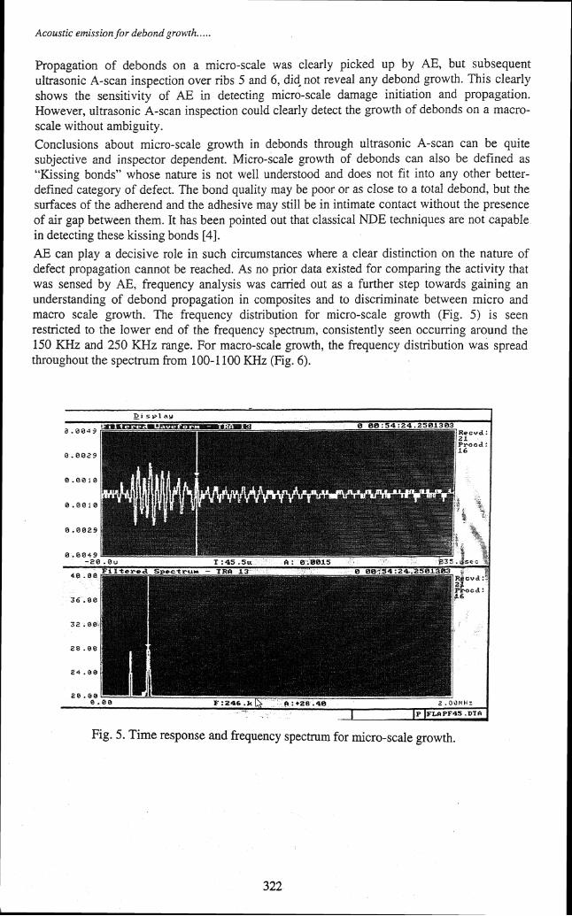
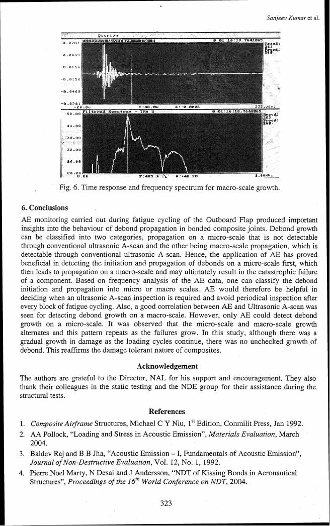
AE can play a decisive role in such circumstances where a clear distinction on the nature of defect propagation cannot be reached. As no prior data existed for comparing the activity that was sensed by AE, frequency analysis was carried out as a further step towards gaining an understanding of debond propagation in composites and to discriminate between micro and macro scale growth. The frequency distribution for micro-scale growth (Fig. 5) is seen restricted to the lower end of the frequency spectrum, consistently seen occurring around the 150 KHz and 250 KHz range. For macro-scale growth, the frequency distribution was spread throughout the spectrum from 100-1 100 KHz (Fig. 6).
Fig. 5. Time response and frequency spectrum for micro-scale growth.
Sanjeev Kurnar et al.
Fig. 6. Time response and frequency spectrum for macro-scale growth.
6. Conclusions
AE monitoring carried out during fatigue cycling of the Outboard Flap produced important insights into the behaviour of debond propagation in bonded composite joints. Debond growth can be classified into two categories, propagation on a micro-scale that is not detectable through conventional ultrasonic A-scan and the other being macro-scale propagation, which is detectable through conventional ultrasonic A-scan. Hence, the application of AE has proved beneficial in detecting the initiation and propagation of debonds on a micro-scale first, which then leads to propagation on a macro-scale and may ultimately result in the catastrophic failure of a component. Based on frequency analysis of the AE data, one can classify the debond initiation and propagation into micro or macro scales. AE would therefore be helpful in deciding when an ultrasonic A-scan inspection is required and avoid periodical inspection after every block of fatigue cycling. Also, a good correlation between AE and Ultrasonic A-scan was seen for detecting debond growth on a macro-scale. However, only AE could detect debond growth on a micro-scale. It was observed that the micro-scale and macro-scale growth alternates and this pattern repeats as the failures grow. In this study, although there was a gradual growth in damage as the loading cycles continue, there was no unchecked growth of debond. This reaffirms the damage tolerant nature of composites.
Acknowledgement
The authors are grateful to the Director, NAL for his support and encouragement. They also thank their colleagues in the static testing and the NDE group for their assistance during the structural tests.
References
1. Composite Airframe Structures, Michael C Y Niu, lS' Edition, Conmilit Press, Jan 1992. 2. AA Pollock, "Loading and Stress in Acoustic Emission", Materials Evaluation, March
2004. 3. Baldev Raj and B B Jha, "Acoustic Emission - I, Fundamentals of Acoustic Emission",
Journal of Non-Destructive Evaluation, Vol. 12, No. 1, 1992. 4. Pierre Noel Marty, N Desai and J Andersson, "NDT of Kissing Bonds in Aeronautical
Structures", Proceedings of the 161h World Conference on NDT, 2004.