xilinx platform specification format reference manual
TRANSCRIPT

UG642 (v14.1) April 24, 2012 [optional]
Platform Specification Format Reference ManualEmbedded Development Kit (EDK) 14.1
UG642 (v14.1) April 24, 2012
This document applies to the following software versions: ISE Design Suite 14.1 and laterThis document applies to the following software versions: ISE Design Suite 14.1 and laterThis document applies to the following software versions: ISE Design Suite 14.1 and laterThis document applies to the following software versions: ISE Design Suite 14.1 and later

Platform Specification Format Reference Manual www.xilinx.com UG642 (v14.1) April 24, 2012
Xilinx is disclosing this user guide, manual, release note, and/or specification (the “Documentation”) to you solely for use in the development of designs to operate with Xilinx hardware devices. You may not reproduce, distribute, republish, download, display, post, or transmit the Documentation in any form or by any means including, but not limited to, electronic, mechanical, photocopying, recording, or otherwise, without the prior written consent of Xilinx. Xilinx expressly disclaims any liability arising out of your use of the Documentation. Xilinx reserves the right, at its sole discretion, to change the Documentation without notice at any time. Xilinx assumes no obligation to correct any errors contained in the Documentation, or to advise you of any corrections or updates. Xilinx expressly disclaims any liability in connection with technical support or assistance that may be provided to you in connection with the Information.
THE DOCUMENTATION IS DISCLOSED TO YOU “AS-IS” WITH NO WARRANTY OF ANY KIND. XILINX MAKES NO OTHER WARRANTIES, WHETHER EXPRESS, IMPLIED, OR STATUTORY, REGARDING THE DOCUMENTATION, INCLUDING ANY WARRANTIES OF MERCHANTABILITY, FITNESS FOR A PARTICULAR PURPOSE, OR NONINFRINGEMENT OF THIRD-PARTY RIGHTS. IN NO EVENT WILL XILINX BE LIABLE FOR ANY CONSEQUENTIAL, INDIRECT, EXEMPLARY, SPECIAL, OR INCIDENTAL DAMAGES, INCLUDING ANY LOSS OF DATA OR LOST PROFITS, ARISING FROM YOUR USE OF THE DOCUMENTATION.
© Copyright 2012 Xilinx, Inc. XILINX, the Xilinx logo, Virtex, Spartan, ISE, and other designated brands included herein are trademarks of Xilinx in the United States and other countries. All other trademarks are the property of their respective owners.
Revision HistoryThe following table shows the revision history for this document.
Date Revision
03/31/2009 EDK 11.1 release.
06/24/2009 EDK 11.2 release.
04/19/2010 EDK 12.1 release.
07/23/2010 EDK 12.2 release.
09/21/2010 EDK 12.3 release.
03/01/2011 EDK 13.1 release.
07/06/2011 EDK 13.2 release.
• Modified description of RUN_NGCBUILD. • Changed allowable values in *_DATA_WIDTH parameters for AXI.• Changed references to tri-state to 3-state. • Added new IO_TYPE/IO_INTERFACE parameters.• Standardized the “Additional Resources” to refer to Appendix A.
01/18/2012 EDK 13.4 release.
• Added information about .mif files in Chapter 6, Black-Box Definition (BBD).
• Added information about .mui files in Chapter 5, Microprocessor-IP User Interface (MUI).
04/24/2012 EDK 14.1 release.
• Added information about the ADDITIONAL_OUTPUTS option keyword.

Platform Specification Format Reference Manual www.xilinx.com 3UG642 (v14.1) April 24, 2012
Revision History . . . . . . . . . . . . . . . . . . . . . . . . . . . . . . . . . . . . . . . . . . . . . . . . . . . . . . . . . . . . . 2
Chapter 1: IntroductionFiles . . . . . . . . . . . . . . . . . . . . . . . . . . . . . . . . . . . . . . . . . . . . . . . . . . . . . . . . . . . . . . . . . . . . . . . . . 7File and IP Naming Rules . . . . . . . . . . . . . . . . . . . . . . . . . . . . . . . . . . . . . . . . . . . . . . . . . . . . 8Load Path . . . . . . . . . . . . . . . . . . . . . . . . . . . . . . . . . . . . . . . . . . . . . . . . . . . . . . . . . . . . . . . . . . . . 9Creating Your IP . . . . . . . . . . . . . . . . . . . . . . . . . . . . . . . . . . . . . . . . . . . . . . . . . . . . . . . . . . . . 10Creating HDL Libraries for Your IP. . . . . . . . . . . . . . . . . . . . . . . . . . . . . . . . . . . . . . . . . . 11Verilog Include Directories. . . . . . . . . . . . . . . . . . . . . . . . . . . . . . . . . . . . . . . . . . . . . . . . . . 12
Chapter 2: Microprocessor Hardware Specification (MHS)MHS Syntax . . . . . . . . . . . . . . . . . . . . . . . . . . . . . . . . . . . . . . . . . . . . . . . . . . . . . . . . . . . . . . . . 13Bus Interface . . . . . . . . . . . . . . . . . . . . . . . . . . . . . . . . . . . . . . . . . . . . . . . . . . . . . . . . . . . . . . . . 17Global Parameter . . . . . . . . . . . . . . . . . . . . . . . . . . . . . . . . . . . . . . . . . . . . . . . . . . . . . . . . . . . 18Local Parameter . . . . . . . . . . . . . . . . . . . . . . . . . . . . . . . . . . . . . . . . . . . . . . . . . . . . . . . . . . . . . 18Global Port . . . . . . . . . . . . . . . . . . . . . . . . . . . . . . . . . . . . . . . . . . . . . . . . . . . . . . . . . . . . . . . . . 19Local Port . . . . . . . . . . . . . . . . . . . . . . . . . . . . . . . . . . . . . . . . . . . . . . . . . . . . . . . . . . . . . . . . . . . 21Design Considerations . . . . . . . . . . . . . . . . . . . . . . . . . . . . . . . . . . . . . . . . . . . . . . . . . . . . . . 21AXI Systems . . . . . . . . . . . . . . . . . . . . . . . . . . . . . . . . . . . . . . . . . . . . . . . . . . . . . . . . . . . . . . . . 23
Chapter 3: Microprocessor Peripheral Definition (MPD)MPD Syntax . . . . . . . . . . . . . . . . . . . . . . . . . . . . . . . . . . . . . . . . . . . . . . . . . . . . . . . . . . . . . . . . 27Bus Interface . . . . . . . . . . . . . . . . . . . . . . . . . . . . . . . . . . . . . . . . . . . . . . . . . . . . . . . . . . . . . . . . 31IO Interface . . . . . . . . . . . . . . . . . . . . . . . . . . . . . . . . . . . . . . . . . . . . . . . . . . . . . . . . . . . . . . . . . 33Option . . . . . . . . . . . . . . . . . . . . . . . . . . . . . . . . . . . . . . . . . . . . . . . . . . . . . . . . . . . . . . . . . . . . . . 34Parameter . . . . . . . . . . . . . . . . . . . . . . . . . . . . . . . . . . . . . . . . . . . . . . . . . . . . . . . . . . . . . . . . . . . 41Ports . . . . . . . . . . . . . . . . . . . . . . . . . . . . . . . . . . . . . . . . . . . . . . . . . . . . . . . . . . . . . . . . . . . . . . . . 55Design Considerations . . . . . . . . . . . . . . . . . . . . . . . . . . . . . . . . . . . . . . . . . . . . . . . . . . . . . . 67
Chapter 4: Peripheral Analyze Order (PAO)PAO Format. . . . . . . . . . . . . . . . . . . . . . . . . . . . . . . . . . . . . . . . . . . . . . . . . . . . . . . . . . . . . . . . . 73Verilog Include Directories. . . . . . . . . . . . . . . . . . . . . . . . . . . . . . . . . . . . . . . . . . . . . . . . . . 74PAO Example . . . . . . . . . . . . . . . . . . . . . . . . . . . . . . . . . . . . . . . . . . . . . . . . . . . . . . . . . . . . . . . 74
Chapter 5: Microprocessor-IP User Interface (MUI)Types of IP Dialog Boxes . . . . . . . . . . . . . . . . . . . . . . . . . . . . . . . . . . . . . . . . . . . . . . . . . . . . 75Organization of a MUI File . . . . . . . . . . . . . . . . . . . . . . . . . . . . . . . . . . . . . . . . . . . . . . . . . . 77Validating the MUI File . . . . . . . . . . . . . . . . . . . . . . . . . . . . . . . . . . . . . . . . . . . . . . . . . . . . . 80
Table of Contents

4 www.xilinx.com Platform Specification Format Reference ManualUG642 (v14.1) April 24, 2012
Chapter 6: Black-Box Definition (BBD)BBD Format . . . . . . . . . . . . . . . . . . . . . . . . . . . . . . . . . . . . . . . . . . . . . . . . . . . . . . . . . . . . . . . . . 81BBD Examples . . . . . . . . . . . . . . . . . . . . . . . . . . . . . . . . . . . . . . . . . . . . . . . . . . . . . . . . . . . . . . 82
Chapter 7: Microprocessor Software Specification (MSS)Overview . . . . . . . . . . . . . . . . . . . . . . . . . . . . . . . . . . . . . . . . . . . . . . . . . . . . . . . . . . . . . . . . . . . 83MSS Format. . . . . . . . . . . . . . . . . . . . . . . . . . . . . . . . . . . . . . . . . . . . . . . . . . . . . . . . . . . . . . . . . 83Global Parameters . . . . . . . . . . . . . . . . . . . . . . . . . . . . . . . . . . . . . . . . . . . . . . . . . . . . . . . . . . 86Instance-Specific Parameters . . . . . . . . . . . . . . . . . . . . . . . . . . . . . . . . . . . . . . . . . . . . . . . . 86
Chapter 8: Microprocessor Library Definition (MLD)Overview . . . . . . . . . . . . . . . . . . . . . . . . . . . . . . . . . . . . . . . . . . . . . . . . . . . . . . . . . . . . . . . . . . . 93Requirements . . . . . . . . . . . . . . . . . . . . . . . . . . . . . . . . . . . . . . . . . . . . . . . . . . . . . . . . . . . . . . . 93Library Definition Files . . . . . . . . . . . . . . . . . . . . . . . . . . . . . . . . . . . . . . . . . . . . . . . . . . . . . 93MLD Format Specification . . . . . . . . . . . . . . . . . . . . . . . . . . . . . . . . . . . . . . . . . . . . . . . . . . 94MLD Parameter Description Section. . . . . . . . . . . . . . . . . . . . . . . . . . . . . . . . . . . . . . . . . 98Design Rule Check (DRC) Section . . . . . . . . . . . . . . . . . . . . . . . . . . . . . . . . . . . . . . . . . . 105Library Generation (Generate) Section. . . . . . . . . . . . . . . . . . . . . . . . . . . . . . . . . . . . . . 105
Chapter 9: Microprocessor Driver Definition (MDD)Overview . . . . . . . . . . . . . . . . . . . . . . . . . . . . . . . . . . . . . . . . . . . . . . . . . . . . . . . . . . . . . . . . . . 107Requirements . . . . . . . . . . . . . . . . . . . . . . . . . . . . . . . . . . . . . . . . . . . . . . . . . . . . . . . . . . . . . . 107Driver Definition Files . . . . . . . . . . . . . . . . . . . . . . . . . . . . . . . . . . . . . . . . . . . . . . . . . . . . . 107MDD Format Specification . . . . . . . . . . . . . . . . . . . . . . . . . . . . . . . . . . . . . . . . . . . . . . . . . 108MDD Parameter Description . . . . . . . . . . . . . . . . . . . . . . . . . . . . . . . . . . . . . . . . . . . . . . . 111Design Rule Check (DRC) Section . . . . . . . . . . . . . . . . . . . . . . . . . . . . . . . . . . . . . . . . . . 115Driver Generation (Generate) Section . . . . . . . . . . . . . . . . . . . . . . . . . . . . . . . . . . . . . . 116
Chapter 10: Xilinx Board Description (XBD) FormatOverview . . . . . . . . . . . . . . . . . . . . . . . . . . . . . . . . . . . . . . . . . . . . . . . . . . . . . . . . . . . . . . . . . . 117XBD Syntax . . . . . . . . . . . . . . . . . . . . . . . . . . . . . . . . . . . . . . . . . . . . . . . . . . . . . . . . . . . . . . . . 117Global Attribute Commands . . . . . . . . . . . . . . . . . . . . . . . . . . . . . . . . . . . . . . . . . . . . . . . 119Local Attribute Commands . . . . . . . . . . . . . . . . . . . . . . . . . . . . . . . . . . . . . . . . . . . . . . . . . 120Local Parameter Commands . . . . . . . . . . . . . . . . . . . . . . . . . . . . . . . . . . . . . . . . . . . . . . . . 121Local Parameter Subproperties . . . . . . . . . . . . . . . . . . . . . . . . . . . . . . . . . . . . . . . . . . . . . 121Local Port Commands . . . . . . . . . . . . . . . . . . . . . . . . . . . . . . . . . . . . . . . . . . . . . . . . . . . . . . 122Local Port Subproperties . . . . . . . . . . . . . . . . . . . . . . . . . . . . . . . . . . . . . . . . . . . . . . . . . . . 122Associating IPs with IO_INTERFACE in XBD . . . . . . . . . . . . . . . . . . . . . . . . . . . . . . 123Bridging IP with IO_INTERFACE . . . . . . . . . . . . . . . . . . . . . . . . . . . . . . . . . . . . . . . . . . 126XBD Load Path . . . . . . . . . . . . . . . . . . . . . . . . . . . . . . . . . . . . . . . . . . . . . . . . . . . . . . . . . . . . . 126Board-Specific IP Constraints . . . . . . . . . . . . . . . . . . . . . . . . . . . . . . . . . . . . . . . . . . . . . . 127BSB Restrictions . . . . . . . . . . . . . . . . . . . . . . . . . . . . . . . . . . . . . . . . . . . . . . . . . . . . . . . . . . . 127

Platform Specification Format Reference Manual www.xilinx.com 5UG642 (v14.1) April 24, 2012
Existing Xilinx IO Types . . . . . . . . . . . . . . . . . . . . . . . . . . . . . . . . . . . . . . . . . . . . . . . . . . . 127XBD2 . . . . . . . . . . . . . . . . . . . . . . . . . . . . . . . . . . . . . . . . . . . . . . . . . . . . . . . . . . . . . . . . . . . . . . 129
Appendix A: Additional ResourcesXilinx Resources . . . . . . . . . . . . . . . . . . . . . . . . . . . . . . . . . . . . . . . . . . . . . . . . . . . . . . . . . . . 131EDK Documentation . . . . . . . . . . . . . . . . . . . . . . . . . . . . . . . . . . . . . . . . . . . . . . . . . . . . . . . 131EDK Additional Resources . . . . . . . . . . . . . . . . . . . . . . . . . . . . . . . . . . . . . . . . . . . . . . . . . 132

6 www.xilinx.com Platform Specification Format Reference ManualUG642 (v14.1) April 24, 2012

Platform Specification Format Reference Manual www.xilinx.com 7UG642 (v14.1) April 24, 2012
Chapter 1
Introduction
Embedded Toolkit (EDK) tools are designed to operate in a data-driven manner. Meta-data files capture information about IPs, drivers, and software libraries used in the EDK tools. ASCII files also capture both the hardware and software information about your design. The set of all these meta-data formats is referred to as the Platform Specification Format or PSF.
Files
MHS - Microprocessor Hardware SpecificationThe Microprocessor Hardware Specification (MHS) file defines the hardware components. You supply an MHS file as an input to the Platform Generator (Platgen) tool.
Refer to Chapter 2, Microprocessor Hardware Specification (MHS), for more information.
MPD - Microprocessor Peripheral DefinitionThe Microprocessor Peripheral Definition (MPD) file defines the interface of the peripheral.
Refer to Chapter 3, Microprocessor Peripheral Definition (MPD), for more information.
PAO - Peripheral Analyze OrderA PAO (Peripheral Analyze Order) file contains a list of HDL files that are needed for synthesis and defines the analyze order for compilation.
Refer to Chapter 4, Peripheral Analyze Order (PAO), for more information.
BBD - Black Box Definition The Black Box Definition (BBD) file manages the file locations of optimized hardware netlists for the black-box sections of your peripheral design.
Refer to Chapter 6, Black-Box Definition (BBD), for more information.
MSS - Microprocessor Software SpecificationYou supply an MSS file as an input to the Library Generator (Libgen). The MSS file contains directives for customizing libraries, drivers, and file systems.
Refer to Chapter 7, Microprocessor Software Specification (MSS), for more information.

8 www.xilinx.com Platform Specification Format Reference ManualUG642 (v14.1) April 24, 2012
Chapter 1: Introduction
MLD - Microprocessor Library DefinitionAn MLD file contains directives for customizing software libraries and operating systems.
Refer to Chapter 8, Microprocessor Library Definition (MLD) for more information.
MDD - Microprocessor Driver DefinitionAn MDD file contains directives for customizing software drivers.
Refer to Chapter 9, Microprocessor Driver Definition (MDD), for more information.
XBD - Xilinx Board DefinitionAn XBD file contains a definition of logical interfaces present on a board and how they are connected to the FPGA. Refer to Chapter 10, Xilinx Board Description (XBD) Format, for more information.
File and IP Naming RulesFile and IP names must be lower-case to ensure consistency across the following:
• OS: Linux (case-sensitive) vs. Win (case-insensitive)
• HDL: Verilog (case-sensitive) vs. VHDL (case-insensitive)
A lower-case naming convention is used in these combinations. For example: MYCORE_v2_1_0 and mycore_v2_1_0 would mean two different files in Linux, whereas in Windows, they would be the same.
Assembly of lower-level cores into the top-level are merged by name reference; the names must match.
Version SchemeThe format of file version levels is X.Y.Z
• X - major revision
• Y - minor revision
• Z - patch level
Version Setting for MHS and MSSIn the body of the MHS and MSS file, add the following statement:
PARAMETER VERSION = 2.1.0
The version is specified as a literal of the form 2.1.0.

Platform Specification Format Reference Manual www.xilinx.com 9UG642 (v14.1) April 24, 2012
Load Path
Version Setting for BBD, MPD, and PAOThe version level is concatenated to the base name of the data files. The literal form of the version level is vX_Y_Z.
• <ipname>_vX_Y_Z.mpd
• <ipname>_vX_Y_Z.bbd
• <ipname>_vX_Y_Z.pao
• <ipname>_vX_Y_Z.mdd
Load Path
Peripheral and pcore Directory StructuresTo specify additional directories, use one of the following options:
• Current directory
• Set the EDK tool -lp option.
EDK tools use a search priority mechanism to locate peripherals, as follows:
1. Search the pcores directory in the project directory.
2. Search <library_path>/<Library Name>/pcores as specified by the -lp option. Figure 1-1 shows the peripheral directory structure.
X-Ref Target - Figure 1-1.
3. Search XILINX_EDK/hw/<Library Name>/pcores. Figure 1-2, page 10 shows the pcore directory structure.
Figure 1-1: Peripheral Directory Structure
X10133
-lp<library_path>
drivers bsp sw_services

10 www.xilinx.com Platform Specification Format Reference ManualUG642 (v14.1) April 24, 2012
Chapter 1: Introduction
X-Ref Target - Figure 1-2
Using VersionsYou can create multiple versions of your peripheral. The version is specified as a literal of the form 1.00.a. The version is always specified in lower case.
At the MHS level, use the HW_VER parameter to set the hardware version. The EDK Tools concatenate a _v and translates periods to underscores. The peripheral name and HW_VER are joined together to form a name for a search level in the load path. For example, if your peripheral is version 1.00.a, then the MPD, BBD, and PAO files are found in:
• <repository_dir>/pcores/<ipname>_v1_00_a/data (Linux)
• <repository_dir>\pcores\<ipname>_v1_00_a\data (PC)
Creating Your IPHow you build your own reference depends on the characteristics of your design.
Is Your IP Pure HDL?Read about MPD and PAO files in the following chapters:
• Chapter 3, Microprocessor Peripheral Definition (MPD)
• Chapter 4, Peripheral Analyze Order (PAO)
Is Your IP Only a Black-Box Netlist? Read about MPD and BBD files in the following chapters:
• Chapter 3, Microprocessor Peripheral Definition (MPD)
• Chapter 6, Black-Box Definition (BBD)
Figure 1-2: pcore Directory Structure
X11000
pcores
<mycore_v1_00_a>
data
.mpd .pao .bbd .tcl
.vhd
.v
vhdl htmlverilog
hdl doc
change_log.html

Platform Specification Format Reference Manual www.xilinx.com 11UG642 (v14.1) April 24, 2012
Creating HDL Libraries for Your IP
Is Your IP a Mixture of Black-Box Netlists and VHDL or Verilog?Read about the MPD, PAO, and BBD files in the following chapters:
• Chapter 3, Microprocessor Peripheral Definition (MPD)
• Chapter 4, Peripheral Analyze Order (PAO)
• Chapter 6, Black-Box Definition (BBD)
Creating HDL Libraries for Your IPThere are two classes of design libraries: primary libraries and resource libraries.
Primary LibraryThe library into which the library unit resulting from the analysis of an IP is placed. A primary library contains all the primary HDL files for the IP, and is referenced in the PAO as <ipname>_v1_00_a.
Only primary libraries contain an MPD file; resource libraries do not.
Resource Library A resource library contains library units that are referenced within the IP being analyzed, and contains all the resource HDL files for the IP, and is referenced in the PAO file as <resource_name>_v1_00_a.
Resource libraries must contain a PAO file to enable primary libraries access to the PAO file set from the resource library. To accomplish this from the primary library PAO, use the all keyword. For example:
# primary_core PAOlib reference_lib_v1_00_a all
Resource Libraries and PAO Files
If a resource library defines a PAO, the language field must be present. Refer to Chapter 4, Peripheral Analyze Order (PAO) for complete details.
For example:
# reference_lib PAOlib reference_lib_v1_00_a file2.vhd vhdllib reference_lib_v1_00_a file1.vhd vhdl
Library File LocationsPrimary and resource libraries are physically located in <repository_dir>/pcores.
Resource HDL File Locations
For VHDL:
<repository_dir>/pcores/<resource_name>_v1_00_a/hdl/vhdl
For Verilog:
<repository_dir>/pcores/<resource_name>_v1_00_a/hdl/verilog

12 www.xilinx.com Platform Specification Format Reference ManualUG642 (v14.1) April 24, 2012
Chapter 1: Introduction
Primary HDL File Locations
For VHDL:
<repository_dir>/pcores/<ipname>_v1_00_a/hdl/vhdl
For Verilog:
<repository_dir>/pcores/<ipname>_v1_00_a/hdl/verilog
Verilog Include DirectoriesYou must use relative paths to allow project maneuverability from development platform to development platform. Use the `include compiler directive in your Verilog HDL files to insert the contents of an entire file.
The following is an example Verilog HDL file:
`include "global_consts.v"`include "pcore_v1_00_a/hdl/verilog/consts.v"
By default, all known EDK repositories are automatically included to the calls that process Verilog:
<proj_dir>/pcores$XILINX_EDK/hw/XilinxBFMinterface/pcores$XILINX_EDK/hw/XilinxProcessorIPLib/pcores$XILINX_EDK/hw/XilinxReferenceDesigns/pcores
You need only specify include paths that are not default. User-specified paths have a higher precedence over the default paths.
FormatUse the following format:
vlgincdir <library> <relative path from library>
RestrictionsIf you intend to define a library file of text macros, you must give each text macro a unique name. The IEEE document 1364-2006 Section 3.12 defines the Verilog name space.
The text macro name space is global. The text macro names are defined in the linear order of appearance in the set of input files that make up the description of the design unit.
Subsequent definitions of the same name override the previous definitions for the balance of the input files.
Use unique names, as follows:
`define PCORE_V1_00_A_MASKVAL 2’b10
(Do not use `define MASKVAL 2’b10.)
When multiple vlgincdir options are in use, it is possible for the compiler to read an unwanted included file. The preferred use of text inclusion within Verilog files is to include the relative path of the pcore library in use, as shown in the following example:
`include "pcore_v1_00_a/hdl/verilog/consts.v"

Platform Specification Format Reference Manual www.xilinx.com 13UG642 (v14.1) April 24, 2012
Chapter 2
Microprocessor Hardware Specification (MHS)
The Microprocessor Hardware Specification (MHS) file defines the hardware component. An MHS file defines the configuration of the embedded processor system, and includes the following:
• Bus architecture
• Peripherals
• Processor
• Connectivity
• Address space
MHS Syntax
About the SyntaxMHS file syntax is case insensitive. The current version is 2.1.0.
MHS parameter, component, instance, and signal names must be HDL, VHDL, and Verilog compliant. VHDL and Verilog have certain naming rules and conventions that must be followed.
Because the MHS stands as a neutral format on top of HDL, VHDL, and Verilog, it is possible to generate invalid VHDL or Verilog, even if the MHS is syntactically correct. You might, therefore, be violating syntax rules in either VHDL or Verilog in the downstream HDL compliant synthesis and simulation tools.
For example, it is invalid in VHDL to use an instance name that already exists as a component name. Consider the following example:
microBlazeport map ( <snip> );

14 www.xilinx.com Platform Specification Format Reference ManualUG642 (v14.1) April 24, 2012
Chapter 2: Microprocessor Hardware Specification (MHS)
However, Verilog allows such a declaration:
microblaze microblaze ( <snip> );
It is also invalid in VHDL to declare an object (parameter, component, instance, or signal) name that already exists as the name of another object. For example, it is invalid to declare a signal name in VHDL as MYTESTNAME and also to declare an instance name of MYTESTNAME.
signal MYTESTNAME : std_logic;MYTESTNAME : microblazeport map ( <snip> );
However, this is valid in Verilog.
It is your responsibility to recognize the output format and comply with the rules of the HDL language.
CommentsYou can insert comments in the MHS file without disrupting processing. The guidelines for inserting comments are:
• Precede comments with the pound sign (#).
• Comments can continue to the end of the line.
• Comments can be anywhere on the line.
FormatUse the following format at the beginning of a component definition:
BEGIN peripheral_name
The BEGIN keyword signifies the beginning of a new component.
Use the following format for assignment commands:
command name = value
Use the following format to end a component definition:
END
There are three assignment commands:
• BUS_INTERFACE
• PARAMETER
• PORT

Platform Specification Format Reference Manual www.xilinx.com 15UG642 (v14.1) April 24, 2012
MHS Syntax
MHS ExampleThe following is an example MHS file:
# ParametersPARAMETER VERSION = 2.1.0
# Global Ports
# Assign power signalsPORT vcc_out = net_vcc, DIR=OUTPUTPORT gnd_out = net_gnd, DIR=OUTPORT gnd_out6 = net_gnd, DIR=OUTPUT, VEC=[0:5]
PORT intr1 = intr_1, DIR=IN, SENSITIVITY=EDGE_RISING, SIGIS=INTERRUPTPORT intr2 = intr2, DIR=INPUT, SENSITIVITY=LEVEL_HIGH, SIGIS=INTERRUPT
# Assign constant signalsPORT const1 = 0b1010, DIR=OUTPUT, VEC=[0:3]PORT const2 = 0xC, DIR=OUTPUT, VEC=[0:3]
PORT sys_rst = sys_rst, DIR=INPORT sys_clk = sys_clk, DIR=IN, SIGIS=CLK, CLK_FREQ=100000000PORT gpio_io = gpio_io, DIR=INOUT, VEC=[0:31]
# Sub Components
######################################################################BEGIN lmb_v10PARAMETER INSTANCE = ilmb_v10PARAMETER HW_VER = 1.00.aPORT LMB_Clk = sys_clkPORT SYS_Rst = sys_rstEND######################################################################BEGIN lmb_v10PARAMETER INSTANCE = dlmb_v10PARAMETER HW_VER = 1.00.aPORT LMB_Clk = sys_clkPORT SYS_Rst = sys_rstEND######################################################################BEGIN opb_v20PARAMETER INSTANCE = myopb_busPARAMETER HW_VER = 1.10.cPARAMETER C_PROC_INTRFCE = 0PORT OPB_Clk = sys_clkPORT SYS_Rst = sys_rstEND######################################################################BEGIN opb_gpioPARAMETER INSTANCE = mygpioPARAMETER HW_VER = 1.00.aPARAMETER C_GPIO_WIDTH = 32PARAMETER C_BASEADDR = 0xffff0100PARAMETER C_HIGHADDR = 0xffff01ffPORT GPIO_IO = gpio_ioBUS_INTERFACE SOPB = myopb_busEND

16 www.xilinx.com Platform Specification Format Reference ManualUG642 (v14.1) April 24, 2012
Chapter 2: Microprocessor Hardware Specification (MHS)
######################################################################BEGIN bram_blockPARAMETER INSTANCE = bram1PARAMETER HW_VER = 1.00.aBUS_INTERFACE PORTA = ilmb1_portaBUS_INTERFACE PORTB = dlmb1_portbEND######################################################################BEGIN lmb_bram_if_cntlrPARAMETER INSTANCE = my_ilmb_cntlr1PARAMETER HW_VER = 1.00.bPARAMETER C_BASEADDR = 0x00000000PARAMETER C_HIGHADDR = 0x00000fffBUS_INTERFACE SLMB = ilmb_v10BUS_INTERFACE BRAM_PORT = ilmb1_portaEND######################################################################BEGIN lmb_bram_if_cntlrPARAMETER INSTANCE = my_dlmb_cntlr1PARAMETER HW_VER = 1.00.bPARAMETER C_BASEADDR = 0x00000000PARAMETER C_HIGHADDR = 0x00000fffBUS_INTERFACE SLMB = dlmb_v10BUS_INTERFACE BRAM_PORT = dlmb1_portbEND######################################################################BEGIN microblazePARAMETER INSTANCE = mblazePARAMETER HW_VER = 4.00.aBUS_INTERFACE DLMB = dlmb_v10BUS_INTERFACE ILMB = ilmb_v10BUS_INTERFACE DOPB = myopb_busPORT Interrupt = mblaze_intrEND####################################################################### Priorities are numbered N downto 1, where 1 is the highest priorityBEGIN opb_intcPARAMETER INSTANCE = opb_intc_1PARAMETER HW_VER = 1.00.cPARAMETER C_HIGHADDR = 0xC800001FPARAMETER C_BASEADDR = 0xC8000000PARAMETER C_HAS_IPR = 1 # Interrupt Pending Register presentPARAMETER C_HAS_SIE = 0 # Set Interrupt Enable bits not presentPARAMETER C_HAS_CIE = 0 # Clear Interrupt Enable bits not presentPARAMETER C_HAS_IVR = 0 # Interrupt Vector Register not presentBUS_INTERFACE SOPB = myopb_busPORT Intr = intr2 & intr_1 # intr_1 has highest priorityPORT Irq = mblaze_intrEND

Platform Specification Format Reference Manual www.xilinx.com 17UG642 (v14.1) April 24, 2012
Bus Interface
Bus Interface
DefinitionA bus interface is a grouping of interconnecting signals that are related.
Several components often have many of the same ports, requiring redundant port declarations for each component.
A bus interface provides a high level of abstraction for the component connectivity of a common interface. Components can use a bus interface as if it were a single port. In its simplest form, a bus interface can be considered a bundle of signals.
Table 2-1 lists the recommendations for bus labels.
For components that have more than one bus interface, refer to the MPD file for a definition of listed bus interface labels. For example, the data-side OPB and instruction-side OPB are named DOPB and IOPB, respectively.
A bus interface is assigned by name to an instance of the bus in your system.
ExampleFor the SPLB bus instance named “mb_plb,” and a connection to the SPLB slave interface of the OPB Uart Lite is made with the bus_interface command.
BEGIN xps_uartlite PARAMETER INSTANCE = RS232 PARAMETER C_FAMILY = spartan3 PARAMETER C_BAUDRATE = 9600 PARAMETER C_DATA_BITS = 8 PARAMETER C_USE_PARITY = 0 PARAMETER C_ODD_PARITY = 0 PARAMETER HW_VER = 1.01.a PARAMETER C_BASEADDR = 0x84000000 PARAMETER C_HIGHADDR = 0x8400ffff BUS_INTERFACE SPLB = mb_plb PORT RX = fpga_0_RS232_RX_pin PORT TX = fpga_0_RS232_TX_pin
Table 2-1: Bus Labels
Bus Name Description
SDCR Slave DCR interface
SLMB Slave LMB interface
MPLB Master PLB interface
MSPLB Master-slave PLB interface
SPLB Slave PLB interface
S_AXI Slave AXI interface
M_AXI Master AXI interface

18 www.xilinx.com Platform Specification Format Reference ManualUG642 (v14.1) April 24, 2012
Chapter 2: Microprocessor Hardware Specification (MHS)
Bus Interface Keyword(s)
POSITION
Use the POSITION keyword to set the position of the bus interface on the bus. For example, use to define master request priority, or DCR slave rank, in the following format:
BUS_INTERFACE PLB=plb_bus_inst, POSITION=N
Where N is a positive integer. Order is defined from 1 to N.
The order of assignment is retained as listed in the MHS in top-to-bottom order.
Note: When specifying bus interfaces of masters-slaves like MSPLB, there is a possibility that Platgen can error out when you have more masters than slaves on the bus. The reason is that the MSPLB is assigned a position. This means the master interface and the slave interface must reside at the same position. There is a possibility that the assigned position of the slave interface is out of range to the number of slaves on the bus.
Global Parameter
DefinitionA global parameter is defined outside of an instance BEGIN-END block.
Global Parameter
VERSION
Use the VERSION keyword to set the MHS version in the following format:
PARAMETER VERSION = 2.1.0
The version is specified as a literal of the form 2.1.0.
Note: This is the only supported top-level XPS parameter.
Local Parameter
DefinitionA local parameter is defined between an instance BEGIN-END block.
Local ParametersApart from the parameters which are present in the MPD of the core, the following two parameters are allowed in the MHS instance to specify the version and instance name of the core. No other parameters (that are not present in the MPD of the core), can be present in the MHS file; with the exception of AXI designs.:
HW_VERUse the HW_VER keyword to set the hardware version in the following format:
PARAMETER HW_VER = 1.00.a
The version is specified as a literal of the form 1.00.a.

Platform Specification Format Reference Manual www.xilinx.com 19UG642 (v14.1) April 24, 2012
Global Port
INSTANCE
Use the INSTANCE keyword to set the instance name of the peripheral. This keyword is mandatory, and the instance name must be specified in lower-case, in the following format:
PARAMETER INSTANCE = my_uart0
Note: In the case of cores that have an AXI interface, a bunch of other parameters (specified in the Interconnect related parameters section of the MPD chapter) are also allowed to be specified in the MHS.
Global Port
Global Port Keyword SummaryA global port is defined outside of an instance BEGIN-END block. It can have the keywords (sub-properties) listed:
Global Port Keyword Definitions
BUFFER_TYPE
Selects the type of buffer to be inserted on the input port using the BUFFER_TYPE keyword in the following format:
PORT CLK = "", DIR=I, BUFFER_TYPE=IBUF
The available values are the following: bufgdll, ibufg, bufgp, ibuf, bufr, and none.
If the BUFFER_TYPE exists on the MPD port, Platgen raises the property up to the top-level port that is directly connected. If the BUFFER_TYPE exists on the top-level MHS port, it overrides any MPD port definition of BUFFER_TYPE.
The BUFFER_TYPE is translated into an XST pragma resident in the top-level <system> HDL.
Note: This constraint selects the type of buffer to be inserted on the input port. In general, it is best to avoid using this constraint and allow XST to infer the proper buffer. Avoidance of this constraint allows for flexibility across device migration or synthesis tool selection.
For an EDK submodule flow, XST does not infer the buffer as defined by the BUFFER_TYPE. This is correct behavior because it is not expected that IO buffers are present for a submodule flow.
CLK_FREQ
The frequency of the top-level clock port of the system can be specified in the MHS using the CLK_FREQ keyword, as in the following format:
BUFFER_TYPE
CLK_FREQ
DIFFERENTIAL_POLARITY
DIR
RST_POLARITY
SENSITIVITY
SIGIS
VEC

20 www.xilinx.com Platform Specification Format Reference ManualUG642 (v14.1) April 24, 2012
Chapter 2: Microprocessor Hardware Specification (MHS)
PORT sys_clk = sys_clk, DIR = IN, SIGIS = CLK, CLK_FREQ = 100000000
This keyword should only be used with the top-level clock ports. For the tools to read the clock frequency specified using the CLK_FREQ keyword, the port must have the SIGIS=CLK sub-property.
DIFFERENTIAL_POLARITY
Defines the associative ports of the differential buffer.
A differential buffer captures a design level interface signal that is represented as two distinct ports (I and IB), one deemed the “Master” and the other the “slave”.
This is translated to either the IBUFDS, OBUFDS, OBUFTDS, or IOBUFDS.
UNISIM primitives where the I port is represented by the DIFFERENTIAL_POLARITY=P, and the IB port is represented by the DIFFERENTIAL_POLARITY=N keyword-value pairs, and is expressed in the following format:
PORT DATA_p = DATA, DIR=I, DIFFERENTIAL_POLARITY=PPORT DATA_n = DATA, DIR=I, DIFFERENTIAL_POLARITY=N
DIR
The driver direction of a signal is specified by the DIR keyword in the following format:
PORT mysignal = "", DIR=direction
In this example, direction is either I, O, or IO.
RST_POLARITY
The reset polarity of the top-level reset port in the system can be specified in the MHS using the RST_POLARITY keyword, as in the following format:
PORT sys_rst = sys_rst, DIR = IN, SIGIS = RST, RST_POLARITY=1
SENSITIVITY
The sensitivity of an interrupt signal is specified by the SENSITIVITY keyword. This keyword supersedes the EDGE and LEVEL keywords in the following format:
PORT interrupt = "", DIR=O, SENSITIVITY=value, SIGIS=INTERRUPT
In this example, the value is either EDGE_FALLING, EDGE_RISING, LEVEL_HIGH or LEVEL_LOW.
SIGIS
The class of a signal is specified by the SIGIS keyword in the following format:
PORT mysig = "", DIR=O, SIGIS=value
In this example, the value is either CLK, INTERRUPT, or RST. Table 2-2 describes SIGIS usage.

Platform Specification Format Reference Manual www.xilinx.com 21UG642 (v14.1) April 24, 2012
Local Port
VEC
The vector width of a signal is specified by the VEC keyword in the following format:
PORT mysignal = "", DIR=I, VEC=[A:B]
In this example, A and B are positive integer expressions.
Local PortA local port is a port defined between an instance BEGIN-END block. A local port does not have keywords.
Design ConsiderationsThis section identifies general design considerations.
Defining Memory SizeMemory sizes are based on C_BASEADDR and C_HIGHADDR settings. Use the following format when defining memory size:
PARAMETER C_HIGHADDR= 0xFFFF00FFPARAMETER C_BASEADDR= 0xFFFF0000
All memory sizes must be 2N, where N is a positive integer and 2N boundary overlaps are not allowed.
The range specified by C_BASEADDR and C_HIGHADDR must comprise a complete, contiguous power-of-two range, such that range = 2N and the N least significant bits of C_BASEADDR must be zero.
Power Signals (net_gnd/net_vcc)Power signals are constantly driven with either GND (net_gnd) or VCC (net_vcc) in the following format:
PORT mysignal = power_signal
Table 2-2: SIGIS Usage
SIGIS Usage
CLK • XPS
Displays all clock signals.
• Platgen
For all bus components, the clock signals are automatically connected to the clock input of the peripherals on the bus.
INTERRUPT • XPS
Displays all interrupt signals.
• Platgen
Encodes the priority interrupt vector.
RST • XPS
Displays all reset signals.

22 www.xilinx.com Platform Specification Format Reference ManualUG642 (v14.1) April 24, 2012
Chapter 2: Microprocessor Hardware Specification (MHS)
In this example, power_signal is either net_vcc or net_gnd. Platgen expands net_vcc or net_gnd to the appropriate vector size. Therefore, it is not legal to use net_vcc or net_gnd in a concatenation construct because the number of bits that are consumed is unknown.
Unconnected PortsUnconnected output ports are assigned open, and unconnected input ports are either set to GND (net_gnd) or VCC (net_vcc).
An unconnected output port is identified as an empty double-quote (““) string.
Platgen resolves the driver value on unconnected input ports with the INITIALVAL keyword, as defined in the MPD in the following format:
PORT mysignal = "", INITIALVAL=VCC
Constant AssignmentsUse the 0b denotation to define a binary constant, or 0x for a hex constant. An underscore (_) can be used for readability in the following format:
PORT mysignal = 0b1010_0101 # mysignal is 8-bits
Or
PORT mysignal = 0xA5 # mysignal is 8-bits
In general, use the 0b syntax for bitwidths that are not evenly divided by 4. Use the 0x syntax for bitwidths that are multiples of 4.
ConcatenationConcatenation is performed with the ampersand (&) operator and allows you to group signals together. It is not legal to use net_vcc or net_gnd in a concatenation construct because the number of bits that are consumed is unknown.
Concatenation combines signals in their bit order. Note, for example, the following top-level port declarations:
PORT A = A, DIR=INPUTPORT B = B, DIR=INPUT, VEC[1:0]PORT C = C, DIR=INPUTPORT D = D, DIR=INPUT, VEC[0:3]PORT Y = A & B & C & D, DIR=OUTPUT, VEC=[7:0]
Concatenation is accomplished on A, B, C, and D connecting to port Y of [7:0]. This maps to the following: Y[7]=A, Y[6]=B[1], Y[5]=B[0], Y[4]=C, Y[3]=D[0], Y[2]=D[1], Y[1]=D[2], and Y[0]=D[3].
Concatenation is also useful for extending the length of a vector. Use the 0b denotation to define a binary constant, or the 0x for a hex constant. An underscore (_) can be used for readability.
Note, for example, the following top-level port:
PORT E = E, DIR=INPUT, VEC=[1:0]PORT Z = 0b00 & E, DIR=OUTPUT, VEC=[0:3]
In this example, the ampersand (&) operator is used to extend the signal E to 4 bits. This maps to the following: Z[0]=0b0, Z[1]=0b0, Z[2]=E[1], and Z[3]=E[0].

Platform Specification Format Reference Manual www.xilinx.com 23UG642 (v14.1) April 24, 2012
AXI Systems
Note: MHS syntax does not support vector indexing. For example, the following syntax is unsupported. The usage of B[1] and B[0] is unsupported.
PORT Y = A & B[1] & B[0] & C & D, DIR=OUTPUT, VEC=[7:0]
Internal vs. External SignalsBy default, all signals defined between a BEGIN-END block are internal signals.
External signals are available through the port-declaration of the top-level module. Use the PORT command outside of a BEGIN-END block to declare the external signal.
External Interrupt SignalsFor internal interrupts, each interruptible, peripheral instance defines an interrupt signal locally.
For external interrupts, use the PORT command outside of a BEGIN-END block to declare the external signal and define the interrupt sensitivity in the following format:
PORT my_int1 = my_int1, LEVEL=HIGH, DIR=I
AXI SystemsTheoretically, an AXI Master (memory mapped) can be directly connected to an AXI Slave (memory mapped). However, XPS tools always requires you to instantiate an AXI Interconnect core between the masters and slaves. The AXU Interconnect degenerates to wires if there is only 1 master and 1 slave on the AXI Interconnect and no data width conversions are required.
The block diagram of a sample AXI system is shown in Figure 2-1. X-Ref Target - Figure 2-1
Figure 2-1: Sample AXI System Block Diagram

24 www.xilinx.com Platform Specification Format Reference ManualUG642 (v14.1) April 24, 2012
Chapter 2: Microprocessor Hardware Specification (MHS)
The following is the MHS representation of the sample AXI system.
BEGIN microblazePARAMETER INSTANCE = mb_0PARAMETER HW_VER = 8.00.aPARAMETER C_INTERCONNECT = 2PARAMETER C_INTERCONNECT_M_AXI_DP_AW_REGISTER = 1BUS_INTERFACE M_AXI_DP = axi_0PORT MB_RESET = mb_resetEND
BEGIN microblazePARAMETER INSTANCE = mb_1PARAMETER HW_VER = 8.00.aPARAMETER C_INTERCONNECT = 2PARAMETER C_INTERCONNECT_M_AXI_DC_AW_REGISTER = 1PARAMETER C_INTERCONNECT_M_AXI_IC_AW_REGISTER = 1BUS_INTERFACE M_AXI_DP = axi_0BUS_INTERFACE M_AXI_DC = axi_1BUS_INTERFACE M_AXI_IC = axi_1PORT CLK = sys_clk_sPORT MB_RESET = mb_resetEND
BEGIN axi_interconnectPARAMETER INSTANCE = axi_0PARAMETER HW_VER = 1.00.aPARAMETER C_INTERCONNECT_DATA_WIDTH = 256PORT INTERCONNECT_ACLK = sys_clk_sPORT INTERCONNECT_ARESETN = sys_bus_reset_nEND
BEGIN axi_interconnectPARAMETER INSTANCE = axi_1PARAMETER HW_VER = 1.00.aPORT INTERCONNECT_ACLK = sys_clk_sPORT INTERCONNECT_ARESETN = sys_bus_reset_nEND
BEGIN axi_gpioPARAMETER INSTANCE = axi_gpio_0PARAMETER HW_VER = 1.00.aPARAMETER C_INTERCONNECT_S_AXI_MASTERS = mb_0.M_AXI_DP & mb_1.M_AXI_DP
PARAMETER C_BASEADDR = 0x81440000PARAMETER C_HIGHADDR = 0x8144ffffBUS_INTERFACE S_AXI = axi_0PORT GPIO_IO_O = fpga_0_LEDs_Positions_GPIO_IO_pin PORT S_AXI_ACLK = sys_clk_sEND
BEGIN axi_v6_ddrxPARAMETER INSTANCE = axi_v6_ddrx_0PARAMETER HW_VER = 1.00.aPARAMETER C_INTERCONNECT_S_AXI_MASTERS = mb_1.M_AXI_DC & mb_1.M_AXI_ICPARAMETER C_BASEADDR = 0x40000000PARAMETER C_HIGHADDR = 0x5fffffff

Platform Specification Format Reference Manual www.xilinx.com 25UG642 (v14.1) April 24, 2012
AXI Systems
BUS_INTERFACE S_AXI = axi_1PORT clk = sys_clk_sEND
BEGIN axi_emcPARAMETER INSTANCE = axi_emc_0PARAMETER HW_VER = 1.00.aPARAMETER C_INTERCONNECT_S_AXI_MASTERS = mb_1.M_AXI_DCPARAMETER C_S_AXI_MEM0_BASEADDR = 0x60000000PARAMETER C_S_AXI_MEM0_HIGHADDR = 0x61ffffffBUS_INTERFACE S_AXI = axi_0PORT S_AXI_ACLK = sys_clk_sEND
BEGIN chipscope_axi_monitorPARAMETER INSTANCE = monitor_1PARAMETER HW_VER = 1.00.aBUS_INTERFACE MON_AXI = mb_1.M_AXI_ICEND
This MHS representation of AXI systems is very similar to that of PLB systems. The addresses of the slaves are still specified on the slaves using the BASEADDR and HIGHADDR parameters.
However, there are four important differences between the MHS representations of PLB designs and AXI designs.
1. The MASTERS parameter: The AXI Interconnect IP is a crossbar. This means that not all masters are connected to all the slaves. There needs to be a mechanism in which slaves that are connected to the AXI Interconnect can specify which masters can access them. This is specified using the C_INTERCONNECT_<BusIf>_MASTERS parameter.
In the previous example, the C_INTERCONNECT_S_AXI_MASTERS parameter on the axi_gpio_0 IP indicates that the M_AXI_DP interface of mb_0 and mb_1 have access. The value of this parameter is an '&' separated list of master interfaces.
2. The INTERCONNECT parameters: Some parameters specified in the mb_0 and mb_1 instances of the Microblaze™ processor core in the MHS are not present in the MPD (of the Microblaze core). These parameters start with the prefix C_INTERCONNECT_<Busif>. An example is PARAMETER C_INTERCONNECT_M_AXI_DP_AW_REGISTER = 1.
The Local Parameter section states that parameters that are not present in the MPD of the cores cannot be present in the MHS, with the exception of the INSTANCE, HW_VER parameters. Also, AXI systems are an exception. This is because some AXII Interconnect-related settings are captured on the end point (masters and slaves) IP interfaces as INTERCONNECT parameters. These parameters are not present in the MPD of the end-point IPs. However, these parameters are allowed in the MHS, as if they were present in the MPD of the cores. The list and description of those parameters is available in Chapter 3, Microprocessor Peripheral Definition (MPD).
3. Clock connections: One other difference between the PLB systems and AXI systems is that in the case of AXI systems, the clock port must be connected explicitly for all the IPs in the design (with the exception of monitors and the axi2axi_connector, for which the tools automate the clock connections).

26 www.xilinx.com Platform Specification Format Reference ManualUG642 (v14.1) April 24, 2012
Chapter 2: Microprocessor Hardware Specification (MHS)
4. Monitor core: Unlike PLB systems where a monitor core monitors the entire bus, the AXI monitor cores can be added in a design to monitor individual interfaces. The MHS syntax in the preceding example is:
BEGIN chipscope_axi_monitorPARAMETER INSTANCE = monitor_1PARAMETER HW_VER = 1.00.aBUS_INTERFACE MON_AXI = mb1.M_AXI_ICEND
The monitor_1 core monitors the M_AXI_IC interface of mb_1 core.
axi2axi_connector core: The axi2axi_connector core is used when two AXI Interconnects need to be cascaded. A sample design is shown in Figure 2-2:
A snippet of the MHS file for the design shown in Figure 2-2, page 26 is:
BEGIN axi2axi_connectorPARAMETER INSTANCE = axi2axi_0PARAMETER HW_VER = 1.00.aPARAMETER C_INTERCONNECT_S_AXI_MASTERS = mb_0.M_AXI_DPPARAMETER C_S_AXI_BASEADDR = 0x81440000PARAMETER C_S_AXI_HIGHADDR = 0x8144ffffBUS_INTERFACE S_AXI = axi_0BUS_INTERFACE M_AXI = axi_1END
BEGIN axi_gpioPARAMETER INSTANCE = axi_gpio_1PARAMETER HW_VER = 1.00.aPARAMETER C_INTERCONNECT_S_AXI_MASTERS = axi2axi_0.M_AXIPARAMETER C_BASEADDR = 0x81440000PARAMETER C_HIGHADDR = 0x8144ffffBUS_INTERFACE S_AXI = axi_1PORT S_AXI_ACLK = sys_clk_sEND
Note: The axi2axi_0 core specifies the masters that can access it using the C_INTERCONNECT_S_AXI_MASTERS parameter. Also, its address range must be specified such that it contains all the addresses of the slaves that are connected on the other side of the axi2axi_connector. The slaves connected on the other side of the axi2axi_connector (to the axi_1 AXI Interconnect), must specify the axi2axi_0.M_AXI as their master.
X-Ref Target - Figure 2-2
Figure 2-2: AXI Sample Design

Platform Specification Format Reference Manual www.xilinx.com 27UG642 (v14.1) April 24, 2012
Chapter 3
Microprocessor Peripheral Definition (MPD)
The Microprocessor Peripheral Definition (MPD) file defines the interface of the peripheral.
An MPD file:
• Lists ports and default connectivity for bus interfaces
• Lists parameters and default values
• Overwrites any MPD parameter by the equivalent MHS assignment.
MPD Syntax
DefinitionMPD file syntax is case insensitive. The version is 2.1.0.
The MPD parameter or signal name must be Hardware Description Language (HDL) compliant. VHDL and Verilog have certain naming rules and conventions that must be followed.
The MPD file is supplied by the IP provider and provides peripheral information. This file lists ports and default connectivity to the bus interface. Parameters that you set in this file are mapped to generics for VHDL, or to parameters for Verilog (with the exception of NON_HDL parameters, which you should specify with the TYPE=NON_HDL keyword).
CommentsYou can insert comments in the MPD file without disrupting processing. The following are guidelines for inserting comments:
• Precede comments with the pound sign (#).
• Comments continue to the end of the line.
• Comments can be anywhere on the line.
FormatUse the following format at the beginning of a component definition:
BEGIN peripheral_name
The BEGIN keyword signifies the beginning of a new peripheral.

28 www.xilinx.com Platform Specification Format Reference ManualUG642 (v14.1) April 24, 2012
Chapter 3: Microprocessor Peripheral Definition (MPD)
Use the following format for assignment commands:
command name = value
Use the following format to end a peripheral definition:
END
Assignment Commands
There are five assignment commands:
• BUS_INTERFACE
• IO_INTERFACE
• OPTION
• PARAMETER
• PORT
MPD ExampleThe following is an example MPD file:
BEGIN xps_gpio
## Peripheral OptionsOPTION IPTYPE = PERIPHERALOPTION IMP_NETLIST = TRUEOPTION HDL = VHDLOPTION LAST_UPDATED = 9.2OPTION USAGE_LEVEL = BASE_USEROPTION DESC = XPS General Purpose IOOPTION LONG_DESC = General Purpose Input/Output (GPIO) core for thePLBV46 bus.
OPTION IP_GROUP = General Purpose IO:MICROBLAZE:PPCOPTION ARCH_SUPPORT_MAP = (spartan3=PREFERRED, virtex4lx=PREFERRED,virtex4sx=PREFERRED, virtex4fx=PREFERRED, spartan3e=PREFERRED,virtex5lx=PREFERRED, virtex5sx=PREFERRED, spartan3a=PREFERRED,spartan3adsp=PREFERRED)
IO_INTERFACE IO_IF = gpio_0, IO_TYPE = XIL_GPIO_V1
## Bus InterfacesBUS_INTERFACE BUS = SPLB, BUS_STD = PLBV46, BUS_TYPE = SLAVE
## Generics for VHDL or Parameters for VerilogPARAMETER C_BASEADDR = 0xffffffff, DT = std_logic_vector(0 to 31), BUS = SPLB, ADDRESS = BASE, PAIR = C_HIGHADDR, MIN_SIZE = 0x200,ASSIGNMENT = REQUIRE
PARAMETER C_HIGHADDR = 0x00000000, DT = std_logic_vector(0 to 31), BUS = SPLB, ADDRESS = HIGH, PAIR = C_BASEADDR, ASSIGNMENT = REQUIRE
PARAMETER C_SPLB_AWIDTH = 32, DT = INTEGER, BUS = SPLB, ASSIGNMENT = CONSTANT
PARAMETER C_SPLB_DWIDTH = 32, DT = INTEGER, BUS = SPLBPARAMETER C_SPLB_P2P = 0, DT = INTEGER, BUS = SPLBPARAMETER C_SPLB_MID_WIDTH = 1, DT = INTEGER, BUS = SPLBPARAMETER C_SPLB_NUM_MASTERS = 1, DT = INTEGER, BUS = SPLBPARAMETER C_SPLB_NATIVE_DWIDTH = 32, DT = INTEGER, BUS = SPLB,ASSIGNMENT = CONSTANT
PARAMETER C_SPLB_SUPPORT_BURSTS = 0, DT = INTEGER, BUS = SPLB,

Platform Specification Format Reference Manual www.xilinx.com 29UG642 (v14.1) April 24, 2012
MPD Syntax
ASSIGNMENT = CONSTANTPARAMETER C_FAMILY = virtex5, DT = STRINGPARAMETER C_GPIO_WIDTH = 32, DT = INTEGER, RANGE = (1:32), PERMIT = BASE_USER, DESC = GPIO Data Width, IO_IF = gpio_0, IO_IS = num_bits
PARAMETER C_ALL_INPUTS = 0, DT = INTEGER, RANGE = (0,1), PERMIT = BASE_USER, DESC = Data pins are all inputs, IO_IF = gpio_0,IO_IS = all_inputs, VALUES = (0= FALSE , 1= TRUE )
PARAMETER C_INTERRUPT_PRESENT = 0, DT = INTEGER, RANGE = (0,1)PARAMETER C_IS_BIDIR = 1, DT = INTEGER, RANGE = (0,1), PERMIT = BASE_USER, DESC = Data pins are bidirectional, IO_IF = gpio_0, IO_IS = is_bidir, VALUES = (0= FALSE , 1= TRUE )
PARAMETER C_DOUT_DEFAULT = 0x00000000, DT = std_logic_vectorPARAMETER C_TRI_DEFAULT = 0xffffffff, DT = std_logic_vectorPARAMETER C_IS_DUAL = 0, DT = INTEGER, RANGE = (0,1), DESC = Use Dual GPIO, IO_IF = gpio_0, IO_IS = is_dual
PARAMETER C_ALL_INPUTS_2 = 0, DT = INTEGER, RANGE = (0,1), DESC = GPIO2Data All Inputs, IO_IF = gpio_0, IO_IS = all_inputs_2, VALUES = (0=FALSE, 1=TRUE)
PARAMETER C_IS_BIDIR_2 = 1, DT = INTEGER, RANGE = (0,1), DESC = Use GPIO2 Bidir IO Pin, IO_IF = gpio_0, IO_IS = is_bidir_2,VALUES = (0=FALSE, 1=TRUE)
PARAMETER C_DOUT_DEFAULT_2 = 0x00000000, DT = std_logic_vectorPARAMETER C_TRI_DEFAULT_2 = 0xffffffff, DT = std_logic_vector
## PortsPORT SPLB_Clk = ““, DIR = I, SIGIS = Clk, BUS = SPLBPORT SPLB_Rst = SPLB_Rst, DIR = I, SIGIS = Rst, BUS = SPLBPORT PLB_ABus = PLB_ABus, DIR = I, VEC = [0:31], BUS = SPLBPORT PLB_UABus = PLB_UABus, DIR = I, VEC = [0:31], BUS = SPLBPORT PLB_PAValid = PLB_PAValid, DIR = I, BUS = SPLBPORT PLB_SAValid = PLB_SAValid, DIR = I, BUS = SPLBPORT PLB_rdPrim = PLB_rdPrim, DIR = I, BUS = SPLBPORT PLB_wrPrim = PLB_wrPrim, DIR = I, BUS = SPLBPORT PLB_masterID = PLB_masterID, DIR = I, VEC = [0:(C_SPLB_MID_WIDTH-1)], BUS = SPLB
PORT PLB_abort = PLB_abort, DIR = I, BUS = SPLBPORT PLB_busLock = PLB_busLock, DIR = I, BUS = SPLBPORT PLB_RNW = PLB_RNW, DIR = I, BUS = SPLBPORT PLB_BE = PLB_BE, DIR = I, VEC = [0:((C_SPLB_DWIDTH/8)-1)], BUS = SPLB
PORT PLB_MSize = PLB_MSize, DIR = I, VEC = [0:1], BUS = SPLBPORT PLB_size = PLB_size, DIR = I, VEC = [0:3], BUS = SPLBPORT PLB_type = PLB_type, DIR = I, VEC = [0:2], BUS = SPLBPORT PLB_lockErr = PLB_lockErr, DIR = I, BUS = SPLBPORT PLB_wrDBus = PLB_wrDBus, DIR = I, VEC = [0:(C_SPLB_DWIDTH-1)], BUS = SPLB
PORT PLB_wrBurst = PLB_wrBurst, DIR = I, BUS = SPLBPORT PLB_rdBurst = PLB_rdBurst, DIR = I, BUS = SPLBPORT PLB_wrPendReq = PLB_wrPendReq, DIR = I, BUS = SPLBPORT PLB_rdPendReq = PLB_rdPendReq, DIR = I, BUS = SPLBPORT PLB_wrPendPri = PLB_wrPendPri, DIR = I, VEC = [0:1], BUS = SPLBPORT PLB_rdPendPri = PLB_rdPendPri, DIR = I, VEC = [0:1], BUS = SPLBPORT PLB_reqPri = PLB_reqPri, DIR = I, VEC = [0:1], BUS = SPLBPORT PLB_TAttribute = PLB_TAttribute, DIR = I, VEC = [0:15], BUS = SPLBPORT Sl_addrAck = Sl_addrAck, DIR = O, BUS = SPLBPORT Sl_SSize = Sl_SSize, DIR = O, VEC = [0:1], BUS = SPLBPORT Sl_wait = Sl_wait, DIR = O, BUS = SPLBPORT Sl_rearbitrate = Sl_rearbitrate, DIR = O, BUS = SPLB

30 www.xilinx.com Platform Specification Format Reference ManualUG642 (v14.1) April 24, 2012
Chapter 3: Microprocessor Peripheral Definition (MPD)
PORT Sl_wrDAck = Sl_wrDAck, DIR = O, BUS = SPLBPORT Sl_wrComp = Sl_wrComp, DIR = O, BUS = SPLBPORT Sl_wrBTerm = Sl_wrBTerm, DIR = O, BUS = SPLBPORT Sl_rdDBus = Sl_rdDBus, DIR = O, VEC = [0:(C_SPLB_DWIDTH-1)], BUS = SPLB
PORT Sl_rdWdAddr = Sl_rdWdAddr, DIR = O, VEC = [0:3], BUS = SPLBPORT Sl_rdDAck = Sl_rdDAck, DIR = O, BUS = SPLBPORT Sl_rdComp = Sl_rdComp, DIR = O, BUS = SPLBPORT Sl_rdBTerm = Sl_rdBTerm, DIR = O, BUS = SPLBPORT Sl_MBusy = Sl_MBusy, DIR = O, VEC = [0:(C_SPLB_NUM_MASTERS-1)], BUS = SPLB
PORT Sl_MWrErr = Sl_MWrErr, DIR = O, VEC = [0:(C_SPLB_NUM_MASTERS-1)],BUS = SPLB
PORT Sl_MRdErr = Sl_MRdErr, DIR = O, VEC = [0:(C_SPLB_NUM_MASTERS-1)],BUS = SPLB
PORT Sl_MIRQ = Sl_MIRQ, DIR = O, VEC = [0:(C_SPLB_NUM_MASTERS-1)], BUS = SPLB
PORT IP2INTC_Irpt = ““, DIR = O, SIGIS = INTERRUPT, SENSITIVITY = LEVEL_HIGH, INTERRUPT_PRIORITY = MEDIUM
PORT GPIO_IO = ““, DIR = IO, VEC = [0:(C_GPIO_WIDTH-1)], THREE_STATE = TRUE, TRI_I = GPIO_IO_I, TRI_O = GPIO_IO_O, TRI_T = GPIO_IO_T, ENABLE = MULTI, PERMIT = BASE_USER, DESC = ‘GPIO1 Data IO’, IO_IF = gpio_0, IO_IS = gpio_io
PORT GPIO_IO_I = ““, DIR = I, VEC = [0:(C_GPIO_WIDTH-1)]PORT GPIO_IO_O = ““, DIR = O, VEC = [0:(C_GPIO_WIDTH-1)]PORT GPIO_IO_T = ““, DIR = O, VEC = [0:(C_GPIO_WIDTH-1)]PORT GPIO_in = ““, DIR = I, VEC = [0:(C_GPIO_WIDTH-1)], PERMIT = BASE_USER, DESC = ‘GPIO1 Data In’, IO_IF = gpio_0, IO_IS = gpio_data_in
PORT GPIO_d_out = ““, DIR = O, VEC = [0:(C_GPIO_WIDTH-1)], PERMIT = BASE_USER, DESC = ‘GPIO1 Data Out’, IO_IF = gpio_0, IO_IS = gpio_data_out
PORT GPIO_t_out = ““, DIR = O, VEC = [0:(C_GPIO_WIDTH-1)], PERMIT = BASE_USER, DESC = ‘GPIO1 3-state Out’, IO_IF = gpio_0, IO_IS = gpio_tri_out
PORT GPIO2_IO = ““, DIR = IO, VEC = [0:(C_GPIO_WIDTH-1)], THREE_STATE = TRUE, TRI_I = GPIO2_IO_I, TRI_O = GPIO2_IO_O, TRI_T = GPIO2_IO_T, ENABLE = MULTI, PERMIT = BASE_USER, DESC = ‘GPIO2 Data IO’, IO_IF = gpio_0, IO_IS = gpio_io_2
PORT GPIO2_IO_I = ““, DIR = I, VEC = [0:(C_GPIO_WIDTH-1)]PORT GPIO2_IO_O = ““, DIR = O, VEC = [0:(C_GPIO_WIDTH-1)]PORT GPIO2_IO_T = ““, DIR = O, VEC = [0:(C_GPIO_WIDTH-1)]PORT GPIO2_in = ““, DIR = I, VEC = [0:(C_GPIO_WIDTH-1)], PERMIT = BASE_USER, DESC = ‘GPIO2 Data In’, IO_IF = gpio_0, IO_IS = gpio_data_in_2
PORT GPIO2_d_out = ““, DIR = O, VEC = [0:(C_GPIO_WIDTH-1)], PERMIT = BASE_USER, DESC = ‘GPIO2 Data Out’, IO_IF = gpio_0, IO_IS = gpio_data_out_2
PORT GPIO2_t_out = ““, DIR = O, VEC = [0:(C_GPIO_WIDTH-1)], PERMIT = BASE_USER, DESC = ‘GPIO2 3-state Out’, IO_IF = gpio_0, IO_IS = gpio_tri_out_2
END

Platform Specification Format Reference Manual www.xilinx.com 31UG642 (v14.1) April 24, 2012
Bus Interface
Bus Interface
DefinitionA bus interface is a grouping of interface ports that are related.
Several components often have many of the same ports, requiring redundant port declarations for each component. Every component connected to a PLB v4.6 bus, for example, must have the same ports defined and connected.
A bus interface provides a high level of abstraction for the component connectivity of a common interface. Components can use a bus interface as if it were a single port. In its simplest form, a bus interface can be considered a bundle of signals.
Bus Interface Keyword Definitions
BUS
The label of a bus interface is specified by the BUS keyword. It is expressed in the following format in which bus_label is a string:
BUS_INTERFACE BUS=bus_label, BUS_STD=bus_std, BUS_TYPE=bus_type
BUS_STD
The bus standard for a bus interface is specified by the BUS_STD keyword. It is expressed in the following format:
BUS_INTERFACE BUS=bus_label, BUS_STD=bus_std, BUS_TYPE=bus_type
The Xilinx-known BUS_STD values are DCR, LMB, OPB, PLB, DSOCM, ISOCM, FSL. You can also define your own bus standards.
Note: BUS_STD = TRANSPARENT is deprecated. It should be replaced with a user-defined “compatibility” string for any point-to-point connections.
BUS_TYPE
The bus type for a bus interface is specified by the BUS_TYPE keyword. It represents the relationship of the interface to the connection. The BUS_TYPE keyword is expressed in the following format:
BUS_INTERFACE BUS=bus_label, BUS_STD=bus_std, BUS_TYPE=bus_type
For centrally connected buses (for example, PLBv4.6), valid values of BUS_TYPE are MASTER, MASTER_SLAVE, SLAVE, and MONITOR.
Note: BUS_TYPE = MASTER_SLAVE is deprecated.
For point-to-point connected bus_interfaces, valid values are INITIATOR, TARGET.
EXCLUDE_BUSIF
Defines all BUS_INTERFACE connections when other BUS_INTERFACE connections are present. Supports a colon-separated list of elements, but can also take a single element.
For example, if two interfaces are defined for an IP as master-slave, or as a slave interface, then only one of them can be used to connect the IP. This keyword is expressed in the following format:

32 www.xilinx.com Platform Specification Format Reference ManualUG642 (v14.1) April 24, 2012
Chapter 3: Microprocessor Peripheral Definition (MPD)
BUS_INTERFACE BUS=MSPLB, BUS_STD=PLB, BUS_TYPE=MASTER_SLAVE, EXCLUDE_BUSIF=SPLBBUS_INTERFACE BUS=SPLB, BUS_STD=PLB, BUS_TYPE=SLAVE, EXCLUDE_BUSIF=MSPLB
GENERATE_BURSTS
Specifies that a non-bridge master generates bursts. This is only valid for BUS_INTERFACEs of BUS_TYPE=MASTER. The keyword is expressed in the following format:
BUS_INTERFACE BUS = MPLB, BUS_STD = PLBV46, BUS_TYPE = MASTER, GENERATE_BURSTS = [FALSE|TRUE]
EDK tools observe all masters and slaves that could communicate through a given bridge. If there is at least one master that has the GENERATE_BURSTS=TRUE, and if there is at least one slave that can support bursts, the bridge is configured to support bursts. To determine whether a slave can support bursts, the EDK tools use the following method:
• If slave does not have the C_<busif>_SUPPORT_BURSTS parameter, the slave BUS_INTERFACE does not support bursts. This means any slave that always supports bursts must also have the parameter.
• If a slave has the C_<busif>_SUPPORT_BURSTS parameter, it is assumed that it can support bursts.
ISVALID
The ISVALID keyword defines the validity of a BUS_INTERFACE to an expression. If the expression evaluates true, the BUS_INTERFACE is included in the list of valid BUS_INTERFACEs for the defined system. If false, the BUS_INTERFACE is not included. It is expressed in the following format:
BUS_INTERFACE BUS = SPLB0, BUS_STD = PLBV46, BUS_TYPE = SLAVE, ISVALID = (C_NUM_PORTS > 0 && C_PIM0_BASETYPE == 2)
SHARES_ADDR
Defines all BUS_INTERFACE address space regions that need to be checked against one another. The default is ALL. This keyword supports a colon-separated list of elements, but can also take a single element.
For example, the LMB and OPB memory mapped peripherals of a MicroBlaze™ processor must not conflict. The PLB and OCM address spaces for a PowerPC® 405 processor must not conflict. This keyword is expressed in the following format:
BUS_INTERFACE BUS=DOPB, BUS_STD=OPB, BUS_TYPE=MASTER, SHARES_ADDR=DLMBBUS_INTERFACE BUS=IOPB, BUS_STD=OPB, BUS_TYPE=MASTER, SHARES_ADDR=ILMBBUS_INTERFACE BUS=DLMB, BUS_STD=LMB, BUS_TYPE=MASTER, SHARES_ADDR=DOPBBUS_INTERFACE BUS=ILMB, BUS_STD=LMB, BUS_TYPE=MASTER, SHARES_ADDR=IOPB

Platform Specification Format Reference Manual www.xilinx.com 33UG642 (v14.1) April 24, 2012
IO Interface
Bus Interface Naming ConventionsTable 3-1 lists recommendations for bus labels.
For the MSPLB bus interface, you should separate the master interface and slave interface as MPLB and SPLB, respectively, because the MSPLB is assigned its own position. This means that the master interface and the slave interface must reside at the same position. If given as separate interfaces for MPLB and SPLB, then each interface can have its own position assignment.
IO Interface
DefinitionDefines an interface between the IP and some external off-chip device. Associated with each IO Interface are sets of ports that the Base System Builder (BSB) Wizard defines as the systems top-level ports, and a set of parameters that BSB characterizes from the off-chip device. In an MPD file, you can define an IO_INTERFACE by assigning it a unique IO_IF name and an IO type (IO_TYPE). You can then specify which ports and parameters are associated with this interface by adding the IO_IF and IO_IS tags to those ports and parameters.
The tools in use the IO_INTERFACE with information from the Xilinx® Board Description (XBD) files to make intelligent decisions for the user regarding system connectivity and parameterization. The IO_INTERFACE declaration and associated tags are not required for core functionality.
I/O Interface KeywordsAn I/O interface can have the following keywords:
IO_IF
A unique, user-defined label assigned an IO_INTERFACE. All ports and parameters declared in an MPD file that are associated with the name IO_INTERFACE have the same IO_IF value assigned to them. This keyword is expressed in the following format, in which io_label is the name of the IO_INTERFACE. This is a user-defined string:
IO_INTERFACE IO_IF=io_label, IO_TYPE=io_type
Table 3-1: Recommended Bus Labels
Bus Label Description
SDCR Slave DCR interface
SLMB Slave LMB interface
MPLB Master PLB interface
MSPLB Master-slave PLB interface
SPLB Slave PLB interface
S_AXI Slave AXI interface
M_AXI Master AXI interface

34 www.xilinx.com Platform Specification Format Reference ManualUG642 (v14.1) April 24, 2012
Chapter 3: Microprocessor Peripheral Definition (MPD)
IO_TYPE
Specifies the I/O type of an I/O interface, expressed in the following format:
IO_INTERFACE IO_IF=io_label, IO_TYPE=io_type
Here, io_type is one of the following values: XIL_DDR_V1, XIL_EMC_V1, XIL_Ethernet_V1, XIL_GPIO_V1, XIL_IIC_V1, XIL_PCI_ARBITER_V1, XIL_PCI32_V1, XIL_SDRAM_V1, XIL_SPI_V1, XIL_SYSACE_V1, or XIL_UART_V1.
Option
DefinitionAn option defines a tool directive.
Option Keyword SummaryAn option can have the following keywords. Select the linked keyword name to go to the description.
Option Keyword Definitions
ADDITIONAL_OUTPUTS
This option must be provided for pcores that produce constraint files and support 7 series devices and above. It can take the following values:
ADDITIONAL_OUTPUTS
ALERT
ARCH_SUPPORT
ARCH_SUPPORT_MAP
BUS_STD
CLK_FREQ_RATIOS
CORE_STATE
DESC
EARLY_ACCESS_ARCH_SUPPORTELABORATE_PROC HDL
IMP_NETLIST
IP_GROUP
IPLEVEL_DRC_PROC
IPTYPE
LAST_UPDATED
LONG_DESC
MAX_MASTERS
MAX_SLAVES
PAY_CORE
PLATGEN_SYSLEVEL_UPDATE_PROC
RUN_NGCBUILD
SPECIAL
STYLE
SYSLEVEL_DRC_PROC
SYSLEVEL_UPDATE_PROC
TCL_FILE
USAGE_LEVEL
Table 3-2: ADDITIONAL_OUTPUTS Values
ADDITIONAL_OUTPUTS Values Definition
CONSTRAINTS The pcore generates both XDC and UCF files.
UCF_CONSTRAINTS The pcore generates only UCF files.
XDC_CONSTRAINTS The pcore generates only XDC files.

Platform Specification Format Reference Manual www.xilinx.com 35UG642 (v14.1) April 24, 2012
Option
ALERT
A message alert for the IP core is specified with the ALERT keyword in the following format:
OPTION ALERT = “This belongs to Xilinx”
ARCH_SUPPORT
Deprecated. Subsumed by ARCH_SUPPORT_MAP.
ARCH_SUPPORT_MAP
This is a list of supported FPGA architectures. Valid values are the various FPGA architectures supported by EDK.
The keys of the map are the architecture names. The architecture names are composed of a concatenation of C_FAMILY and C_SUBFAMILY. The parameter C_FAMILY contains VIRTEX4 and VIRTEX5 as valid values. The C_SUBFAMILY has an FX, LX, or SX designation for VIRTEX4, an LX or SX designation for VIRTEX5, and an empty “” for other architectures.
The key is the primary family name, and value is the core state. It is followed by a comma-separated list of devices. The format is <key name>=<key value>, <key name>=<key value>
The following is an example of the format:
OPTION ARCH_SUPPORT_MAP = (virtex2p=PREFERRED, virtex4=PREFERRED, spartan3a=AVAILABLE, spartan3e=AVAILABLE, virtex5fx=EARLY_ACCESS, spartan2=OBSOLETE)
You can use OTHERS as a key name that expands to all undefined architectures with a common core state, illustrated as follows:
OPTION ARCH_SUPPORT_MAP = (virtex2p = PREFERRED, others = AVAILABLE)OPTION ARCH_SUPPORT_MAP = (others = DEVELOPMENT)
Table 3-3: ARCH_SUPPORT_MAP Values
ARCH_SUPPORT_MAP Definition
PREFERRED Core is active (full uninhibited use) by EDK.
AVAILABLE Core is available (full uninhibited use) by EDK and info message is given to that user.
BETA Core is in beta stage and a warning is issued to the user
DEPRECATED Core is deprecated. EDK tools allow use of core, but issues a warning that the core is deprecated.
DEVELOPMENT Core is in development and is synthesized each time Platgen is executed (no cache of synthesis results).
Note: The Base System Builder in XPS does not recognize cores with ARCH_SUPPORT_MAP value of DEVELOPMENT.
EARLY_ACCESS Core is in early access stage and a warning is issued to the user.
OBSOLETE Core is obsolete. EDK tools issue an error that this core is no longer valid.

36 www.xilinx.com Platform Specification Format Reference ManualUG642 (v14.1) April 24, 2012
Chapter 3: Microprocessor Peripheral Definition (MPD)
Note: Parentheses enclose the beginning and ending of the mapping section. The MPD parse rules require that this be done within one line of the MPD file. You do not have the option to cross multiple lines. However, for descriptive purposes, examples are shown to cross multiple lines.
BUS_STD
This keyword defines the bus standard of BUS or BUS_ARBITER cores, as follows:OPTION BUS_STD = value
In this example, value is one of the following Xilinx®-supported bus standards: DCR, DSOCM, FSL, ISOCM, LMB, OPB, PLBV46, or PLB. You can also define your own bus standard. There is no default.
CLK_FREQ_RATIOS
This option specifies the allowed ratios between clocks in an IP. Its value is a list of comma-separated, name-value pairs. Each such pair has a name that describes:
• The ports whose ratio must be computed
• A value that is the actual ratio allowed
The value can include multiple ratios and is therefore expressed as a comma-separated list. The syntax to specify the value for this option is as follows:
OPTION CLK_FREQ_RATIOS = ( P1/P2 = ( N1/D2, [N2:N3]/D2, N4/[D3:D4], N5 ), (P1,P2)/P3 = ( N6, [N7:N8]/[D5:D6] ) )
In this expression, P1, P2, and P3 are the clock ports in the IP. N is the numerator in the ratio, and D is the denominator. The syntax rules to specify the ratio are given as follows:
• The whole value of the CLK_FREQ_RATIOS option must be specified in parentheses.
• The value of the option is a comma-separated list of name-value pairs, where name is the ratio of ports and value is the list of supported ratios with the syntax Name = (list of values).
• The list of values must be enclosed in parentheses, even if the list has only one element.
• A ratio must be specified as N/D, where N is the numerator and D is the denominator.
• A range (in the numerator or denominator) is only allowed in the list of values section, and it must be specified by using square brackets and a colon. Otherwise, it is considered illegal syntax.
• A range, if specified, cannot contain fractions. Both bounds must be positive integers.
If this option is specified in the MPD of the IP, the tools perform a design rule check (DRC) to verify that the clocks satisfy the ratio requirements in this option. The DRC passes at the first ratio in the list that matches the computed ratio.
CORE_STATE
Deprecated. Subsumed by ARCH_SUPPORT_MAP.
DESC
This keyword allows a short description of the core to be displayed by the GUI tools. The short description replaces the core name in the display field of the core, as in the following format:
OPTION DESC = “XPS GPIO”

Platform Specification Format Reference Manual www.xilinx.com 37UG642 (v14.1) April 24, 2012
Option
EARLY_ACCESS_ARCH_SUPPORT
Deprecated. Subsumed by ARCH_SUPPORT_MAP.
This keyword is a list of FPGA architectures that the core supports in an early access form. There is no default value. It supports a colon-separated list of elements, but can also take a single element, as in the following formats:
OPTION EARLY_ACCESS_ARCH_SUPPORT = virtex5:spartan3eOPTION EARLY_ACCESS_ARCH_SUPPORT = virtex5
ELABORATE_PROC
Defines the Tcl entry point for the IP core’s elaboration. This procedure is run after Platgen completes the merge of MPD and MHS descriptions, and it is suitable for use in Tcl to generate VHDL/VERILOG for the IP core being elaborated.
It is expressed in the following format:
OPTION ELABORATE_PROC = proc_name
HDL
Deprecated. The HDL availability of the IP is specified with the HDL keyword, as in the following format:
OPTION HDL = VERILOG
IMP_NETLIST
The IMP_NETLIST keyword directs Platgen to write an implementation netlist file for the peripheral, as in the following format:
OPTION IMP_NETLIST = TRUE
The default is FALSE. If FALSE, Platgen does not generate an implementation netlist (NGC) file. You must provide a mechanism to synthesize your IP.
IP_GROUP
The IP_GROUP keyword defines the IP group classification. The keyword is expressed in the following format, in which ipgroup_label is a string:
OPTION IP_GROUP = ipgroup_label
If you have more than one IP group sharing the parameter, then use a colon to separate each IP group in the list.
IPLEVEL_DRC_PROC
The IPLEVEL_DRC_PROC keyword defines the Tcl entry point for the IP-level DRC routine. DRCs are based only on IP-level settings. The IPLEVEL_DRC_PROC keyword is expressed following format:
OPTION IPLEVEL_DRC_PROC = proc_name

38 www.xilinx.com Platform Specification Format Reference ManualUG642 (v14.1) April 24, 2012
Chapter 3: Microprocessor Peripheral Definition (MPD)
IPTYPE
Defines the type of the component, as in the following format:
OPTION IPTYPE = PERIPHERAL
Table 3-4 lists IPTYPE values.
Note: The values BRIDGE, IP, and BUS_ARBITER for IPTYPE are deprecated. The following conventions are used to model them:
• IPTYPE=IP is modeled as IPTYPE=PERIPHERAL, and the IP has no address parameters.
• IPTYPE=BUS_ARBITER is modeled as IPTYPE=BUS, and the IP has address parameters.
• IPTYPE=Bridge is modeled at the ADDRESS parameter level using ADDR_TYPE=BRIDGE and BRIDGE_TO tags.
LAST_UPDATED
Indicates the release for which an IP was last updated. It includes the HDL, MPDs, and Tcl files for each IP. The syntax is as follows:
OPTION LAST_UPDATED = <edk_release_number>
The edk_release_number is expressed as a version number, for example, 9.2.
LONG_DESC
Allows a long description of the core to be displayed by the GUI tools. The long description allows the GUI tools to display a floating text box that contains additional help information. There is no default, as in the following format:
OPTION LONG_DESC = "XPS GPIO - IO only, GPIO"
MAX_MASTERS
Defines the maximum number of masters allowed for cores marked as IPTYPE=BUS or IPTYPE=BUS_ARBITER. No default, as in the following format:
OPTION MAX_MASTERS = 8
MAX_SLAVES
Defines the maximum number of slaves allowed for cores marked as IPTYPE=BUS or IPTYPE=BUS_ARBITER. There is no default, as in the following format:
OPTION MAX_SLAVES = 8
Table 3-4: IPTYPE Values
IPTYPE Definition
BUS Bus component.
PERIPHERAL Component that is address-mapped to a bus.
PROCESSOR Processor component.

Platform Specification Format Reference Manual www.xilinx.com 39UG642 (v14.1) April 24, 2012
Option
PAY_CORE
Deprecated. This keyword identifies a core as being free or purchased. PAY_CORE is Xilinx IP-specific and should be used only by Xilinx IPs. PAY_CORE allows a sub-property, ISVALID, which the tools use internally to identify the license status of the core.
PAY_CORE_MAP
Only one definition of PAY_CORE_MAP or PAY_CORE can exist in the MPD. If both exist, PAY_CORE_MAP takes precedence.
The general syntax is:
OPTION PAY_CORE_MAP = (libname:license_key1 = (ISVALID expression1),libname:license_key2 = (ISVALID expression2))
Where:
• libname—Is the HDL file library that contains the defined feature and license pragma.
• license_key—Is the license key for the defined feature.
• ISVALID—Is the conditional expression. If license_key is not conditioned upon an expression, then this field is given a constant value of (1).
Example:
OPTION PAY_CORE_MAP = {soft_temac_wrap_v2_02_a:soft_temac_wrap_v2 = (C_TEMAC_TYPE == 2),avb_wrap_v1_00_a:avb_wrap_v1 = (C_FEATURE2_USED == 1)}
Example:
OPTION PAY_CORE_MAP = {xps_usb2_device_v2_00_a:xps_usb2_device_v2 = (1)}
PLATGEN_SYSLEVEL_UPDATE_PROC
Defines the Tcl entry point for the system-level update routine. This procedure is run after Platgen completes the merge of MPD and MHS descriptions, and it is suitable for use in Tcl to generate UCF entries. The updates are based on system-level settings only, and are expressed in the following format:
OPTION PLATGEN_SYSLEVEL_UPDATE_PROC = proc_name
40 www.xilinx.com Platform Specification Format Reference ManualUG642 (v14.1) April 24, 2012
Chapter 3: Microprocessor Peripheral Definition (MPD)
RUN_NGCBUILD
Directs Platgen to execute NGCBUILD to execute NGCBuild to merge multiple hardware netlists into a single deliverable hardware netlist.
The flow, as implemented in Platgen, is to run XST to generate a netlist from the HDL referred to in the Peripheral Analyze Order (PAO) file. The output netlists (of multiple XST runs) are then combined by running NCGBUILD to create a new IP-level netlist.
RUN_NGCBUILD is required when edk_generatecore is used. It is intuited when a Black Box Definition (BBD) file is present. The RUN_NGCBUILD keyword is expressed in the following format:
OPTION RUN_NGCBUILD = TRUE
The default is FALSE.
SPECIAL
Reserved for internal use only. The SPECIAL keyword defines a class of components that require special handling, as in the following format:
OPTION SPECIAL = BRAM_CNTLR
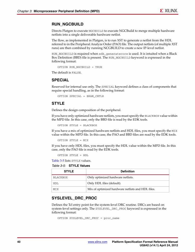
STYLE
Defines the design composition of the peripheral.
If you have only optimized hardware netlists, you must specify the BLACKBOX value within the MPD file. In this case, only the BBD file is read by the EDK tools.
OPTION STYLE = BLACKBOX
If you have a mix of optimized hardware netlists and HDL files, you must specify the MIX value within the MPD file. In this case, the PAO and BBD files are read by the EDK tools.
OPTION STYLE = MIX
If you have only HDL files, you must specify the HDL value within the MPD file. In this case, only the PAO file is read by the EDK tools.
OPTION STYLE = HDL
Table 3-5 lists STYLE values.
SYSLEVEL_DRC_PROC
Defines the Tcl entry point for the system-level DRC routine. DRCs are based on system-level settings only. The SYSLEVEL_DRC_PROC keyword is expressed in the following format:
OPTION SYSLEVEL_DRC_PROC = proc_name
Table 3-5: STYLE Values
STYLE Definition
BLACKBOX Only optimized hardware netlists.
HDL Only HDL files (default).
MIX Mix of optimized hardware netlists and HDL files.

Platform Specification Format Reference Manual www.xilinx.com 41UG642 (v14.1) April 24, 2012
Parameter
SYSLEVEL_UPDATE_PROC
Defines the Tcl entry point for the system-level update routine. The updates are based upon system-level settings only. The keyword is expressed in the following format:
OPTION SYSLEVEL_UPDATE_PROC = proc_name
TCL_FILE
Deprecated. The TCL_FILE keyword defines the Tcl file name. The keyword is expressed in the following format:
OPTION TCL_FILE = opb_gpio_v2_1_0.tcl
USAGE_LEVEL
Defines a tool option BSB uses to determine whether or not BSB should configure this IP module. It is expressed in the following format:
OPTION USAGE_LEVEL = BASE_USER
Table 3-6 lists the USAGE_LEVEL values.
Parameter
DefinitionA parameter defines a constant that is passed into the entity (VHDL) or module (Verilog) declaration.
Parameter Keyword SummaryA parameter can have the following keywords:
Table 3-6: USAGE_LEVEL Values
USAGE_LEVEL Definition
ADVANCED_USER IP cannot be configured by BSB.
BASE_USER IP can be configured by BSB.
ADDRESS
ADDR_TYPE
ASSIGNMENT
BRIDGE_TO
BUS
CACHEABLE
CLK_PORT
CLK_UNIT
DESC
DT
IO_IF
IO_IS
IPLEVEL_DRC_PROC
IPLEVEL_UPDATE_VALUE_PROC
ISVALID
LONG_DESC
MIN_SIZE
PAIR
PERMIT
RANGE
SYSLEVEL_DRC_PROC
SYSLEVEL_UPDATE_VALUE_PROC
TYPE
VALUES

42 www.xilinx.com Platform Specification Format Reference ManualUG642 (v14.1) April 24, 2012
Chapter 3: Microprocessor Peripheral Definition (MPD)
Parameter Keyword Definitions
ADDRESS
Identifies a named parameter as a valid address parameter. The keyword is expressed in the following format:
PARAMETER C_BASEADDR=0xFFFFFFFF, MIN_SIZE=0x2000, ADDRESS=BASE
Table 3-7 lists ADDRESS values.
ADDR_TYPE
Identifies an address parameter of a defined memory class, expressed in the following format:
PARAMETER C_BASEADDR=0xFFFFFFFF, MIN_SIZE=0x2000, ADDR_TYPE=REGISTER
Table 3-8 lists ADDR_TYPE values.
Table 3-7: ADDRESS Values
ADDRESS Definition
BASE Identify base address (default for C_BASEADDR)
HIGH Identify high address (default for C_HIGHADDR)
SIZE Deprecated. Identify size of address (paired with ADDRESS=HIGH or ADDRESS=BASE)
NONE Disable identification of address parameter
Table 3-8: ADDR_TYPE Values
ADDR_TYPE Definition
BRIDGE Address window on the bridge. An address of this type is forwarded to the bus which is slave to the bridge.
MEMORY Address window on the memory controller. An address of this type points to a storage memory, such as SDRAM, DDR, FLASH, or block RAM.
REGISTER Address of its own registers. An address of this type points to registers in the peripheral. These could be status, control, data registers, or some FIFO registers in the peripheral. This is the default.

Platform Specification Format Reference Manual www.xilinx.com 43UG642 (v14.1) April 24, 2012
Parameter
ASSIGNMENT
Defines the assignment usage level. The keyword is expressed in the following format:PARAMETER C_HAS_EXTERNAL_XIN=0, DT=integer, ASSIGNMENT=OPTIONAL
Table 3-9 lists the ASSIGNMENT keyword values.
Examples:
• MPD example of ASSIGNMENT=OPTIONAL_UPDATE:
SYSLEVEL_UPDATE_VALUE_PROCPARAMETER C_MASK=0x00800000, SYSLEVEL_UPDATE_VALUE_PROC = update_syslevel_mask, ASSIGNMENT = OPTIONAL_UPDATE
It is recommended that the IP developer also provide a DRC procedure to validate the user-specified MHS value. Use the SYSLEVEL_DRC_PROC to define the name of the DRC entry point.
• MPD example pairing SYSLEVEL_UPDATE_VALUE_PROC and SYSLEVEL_DRC_PROC (ASSIGNMENT=OPTIONAL_UPDATE inferred):
PARAMETER C_MASK=0x00800000, SYSLEVEL_UPDATE_VALUE_PROC = update_syslevel_mask, SYSLEVEL_DRC_PROC = check_syslevel_mask
In this example, the ASSIGNMENT=OPTIONAL_UPDATE is not listed because it is inferred from the pairing of the SYSLEVEL_UPDATE_VALUE_PROC and SYSLEVEL_DRC_PROC subproperties.
The pairing of IPLEVEL_UPDATE_VALUE_PROC and IPLEVEL_DRC_PROC or SYSLEVEL_UPDATE_VALUE_PROC and SYSLEVEL_DRC_PROC infers the ASSIGNMENT=OPTIONAL_UPDATE.
BRIDGE_TO
Allows an address to be visible through the bridge, expressed in the following format: PARAMETER C_BASEADDR=0xFFFFFFFF, BRIDGE_TO=MPLB
Table 3-9: ASSIGNMENT Values
ASSIGNMENT Definition
CONSTANT This value is a constant; it cannot be modified.
OPTIONAL If you do not specify a value, the EDK batch tools use the default.
OPTIONAL_UPDATE You can specify an MHS value for any parameter associated with a Tcl procedure. The MHS value has precedence over the Tcl-calculated value, as called through IPLEVEL_UPDATE_VALUE_PROC or SYSLEVEL_UPDATE_VALUE_PROC.
REQUIRE You must specify a value.
UPDATE Value is computed by the EDK batch tools; and is not user-specified.
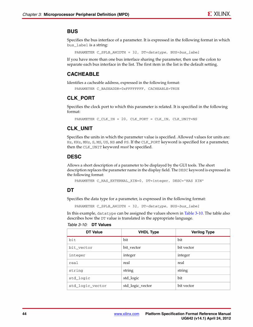
44 www.xilinx.com Platform Specification Format Reference ManualUG642 (v14.1) April 24, 2012
Chapter 3: Microprocessor Peripheral Definition (MPD)
BUS
Specifies the bus interface of a parameter. It is expressed in the following format in which bus_label is a string:
PARAMETER C_SPLB_AWIDTH = 32, DT=datatype, BUS=bus_label
If you have more than one bus interface sharing the parameter, then use the colon to separate each bus interface in the list. The first item in the list is the default setting.
CACHEABLE
Identifies a cacheable address, expressed in the following format: PARAMETER C_BASEADDR=0xFFFFFFFF, CACHEABLE=TRUE
CLK_PORT
Specifies the clock port to which this parameter is related. It is specified in the following format:
PARAMETER C_CLK_IN = 20, CLK_PORT = CLK_IN, CLK_UNIT=NS
CLK_UNIT
Specifies the units in which the parameter value is specified. Allowed values for units are: Hz, KHz, MHz, S, MS, US, NS and PS. If the CLK_PORT keyword is specified for a parameter, then the CLK_UNIT keyword must be specified.
DESC
Allows a short description of a parameter to be displayed by the GUI tools. The short description replaces the parameter name in the display field. The DESC keyword is expressed in the following format:
PARAMETER C_HAS_EXTERNAL_XIN=0, DT=integer, DESC="HAS XIN"
DT
Specifies the data type for a parameter, is expressed in the following format:
PARAMETER C_SPLB_AWIDTH = 32, DT=datatype, BUS=bus_label
In this example, datatype can be assigned the values shown in Table 3-10. The table also describes how the DT value is translated in the appropriate language.
Table 3-10: DT Values
DT Value VHDL Type Verilog Type
bit bit bit
bit_vector bit_vector bit vector
integer integer integer
real real real
string string string
std_logic std_logic bit
std_logic_vector std_logic_vector bit vector

Platform Specification Format Reference Manual www.xilinx.com 45UG642 (v14.1) April 24, 2012
Parameter
IO_IF
The I/O interface association name is expressed in the following format:
PARAMETER C_HAS_EXTERNAL_RCLK=0, IO_IF=uart_0, IO_IS=has_ext_rclk
IO_IS
Defines an XBD relationship marker. IO_IS implies that the parameter value can be dictated by a feature on the external hardware to which this IP is connected. Without a corresponding XBD value the tag has no effect.
A parameter that has an IO_IS must also have an IO_IF association with a particular IO_INTERFACE in the MPD. There are special values of IO_IS that do not have an IO_IF association. This occurs when those values are not specific to a particular IO_INTERFACE. These special values are clk_freq and polarity.
An MPD could have more than one IO_INTERFACE. Therefore, a parameter with an IO_IS must be associated with only one of them. This keyword is expressed in the following format:
PARAMETER C_FAMILY=virtex, IO_IF=uart_0, IO_IS=C_FAMILY
IPLEVEL_DRC_PROC
Defines the Tcl entry point for the IP-level DRC routine. A DRC based only on IP-level settings is done. The IPLEVEL_DRC_PROC keyword is expressed in the following format:
PARAMETER C_SPLB_AWIDTH = 32, IPLEVEL_DRC_PROC = proc_name
IPLEVEL_UPDATE_VALUE_PROC
Defines the Tcl entry point for the IP-level update routine on parameters. An update based on only IP-level settings is done. The IPLEVEL_UPDATE_VALUE_PROC keyword is expressed in the following format:
PARAMETER C_SPLB_AWIDTH = 32, IPLEVEL_UPDATE_VALUE_PROC = proc_name
ISVALID
Defines the validity of a parameter to an expression. If the expression evaluates true, the PARAMETER is included in the list of valid PARAMETERs of the defined system for DRC processing. If false, the PARAMETER is not included, and no DRC is performed. However, the PARAMETER remains listed in the HDL. The ISVALID keyword is expressed in the following format:
PARAMETER C_BASEADDR = 0xFFFFFFFF, ISVALID = (C_PROC_INTRFCE==1)
If the ISVALID expression includes a string comparison, it cannot be specified using the == operator. Instead, the following Tcl procedure and syntax should be used.
PARAMETER C_MEM_PART_DATA_DEPTH = 0, DT = INTEGER, ISVALID = ([xstrncmp C_MEM_PARTNO CUSTOM])
In this example, the expression is valid when the value of the parameter C_MEM_PARTNO is CUSTOM.

46 www.xilinx.com Platform Specification Format Reference ManualUG642 (v14.1) April 24, 2012
Chapter 3: Microprocessor Peripheral Definition (MPD)
LONG_DESC
Allows a long description of the parameter to be displayed by the GUI tools. The long description allows the GUI tools to display a hover help. There is no default, and LONG_DESC is expressed in the following format:
PARAMETER C_HAS_EXTERNAL_XIN=0, DT=integer, LONG_DESC=”XIN? What XIN?”
MIN_SIZE
Specifies the minimum size for an address window, expressed in the following format:
Note: The MIN_SIZE number for an address window must be a power of 2.
PARAMETER C_BASEADDR = 0xFFFFFFFF, DT=std_logic_vector, MIN_SIZE=0x100
PAIR
Tags unidentified BASEADDR-HIGHADDR pairs.
If non-standard names are used instead of *_BASEADDR and *_HIGHADDR, address parameters must identify pairs that define the BASE and HIGH. You must use the ADDRESS keyword to identify the parameter as BASE address or HIGH address. It is expressed in the following format:
PARAMETER C_HIGH=0x00000000, PAIR=C_BASE, ADDRESS=HIGHPARAMETER C_BASE=0xFFFFFFFF, PAIR=C_HIGH, ADDRESS=BASE
PERMIT
Specifies whether BSB should display and lets users edit the parameter. Allowed values are ADVANCED_USER (default) and BASE_USER. Only parameters that are tagged as BASE_USER are shown in BSB. PERMIT is expressed in the following format:
PARAMETER C_HAS_EXTERNAL_XIN=0, DT=integer, PERMIT = BASE_USER, ...
RANGE
Defines a range of allowed valid values. It covers sequences like 8,16,24,32, or breaks in ranges, for example: RANGE=(1:4,8,16). The RANGE keyword is expressed in the following format:
PARAMETER C_HAS_EXTERNAL_XIN=0, DT=integer, RANGE=(0:1)
SYSLEVEL_DRC_PROC
Defines the Tcl entry point for the system level DRC routine. A DRC based on only system-level settings is done. The SYSLEVEL_DRC_PROC keyword is expressed in the following format:
PARAMETER C_SPLB_AWIDTH = 32, SYSLEVEL_DRC_PROC = proc_name
SYSLEVEL_UPDATE_VALUE_PROC
Defines the Tcl entry point for the system-level update routine on parameters. The updates are based only on system-level settings and are expressed in the following format:
PARAMETER C_SPLB_AWIDTH = 32, SYSLEVEL_UPDATE_VALUE_PROC = proc_name

Platform Specification Format Reference Manual www.xilinx.com 47UG642 (v14.1) April 24, 2012
Parameter
TYPE
Defines the kind of parameter. Values are:
• HDLcorrelates to a generic for VHDL, or to a parameter for Verilog.
• NON_HDLthis parameter is not present in the HDL of the IP, and it is tools specific.
If the TYPE keyword is not specified, the default is assumed to be HDL.
Note: The TYPE keyword was introduced to support NON_HDL parameters. Previously, there was a requirement that all parameters of an IP in the MHS and MPD files must be present in the HDL for the IP. However, there were cases in which the tools need user input (specified using parameters) for configuring the IP. Dummy parameters were therefore introduced in the HDL. You can now avoid this workaround by specifying those parameters as NON_HDL using the TYPE keyword.
VALUES
Lists the name-value pairs. The name is a parameter value in the range of allowed valid values. The value is a GUI-representable display string.
The VALUES keyword is expressed in the following format:
PARAMETER C_ODD_PARITY=1, RANGE=(0:1), VALUES=(0=Even, 1=Odd)
Parameter Naming ConventionsAn MPD parameter correlates to a generic for VHDL, or to a parameter for Verilog. The parameter name must be HDL (VHDL, Verilog) compliant. VHDL and Verilog have naming rules and conventions that must be followed.
In the PSF format, any parameter that matches the regular expressions <prefix>_BASEADDR or C_<BUSIFNAME>_BASEADDR is assumed to be an address parameter. The address is associated with slave bus interface associated with the IP.
Similarly, the tools perform automatic clock DRCs and check to see if the frequency (or period) values specified for clock-related parameters in the MHS and MPD files are equal to the values computed by the tools. For this purpose, the tools rely on certain sub-properties (CLK_PORT and CLK_UNIT) to be present for that parameter. If the tools do not find those sub-properties, they try to infer them from the name of the parameter.
If the parameter name follows the convention C_<clock_port>_FREQ_<clock_units> or C_<clock_port>_PERIOD_<clock_units>
The tools then infer the clock name and clock units for that parameter.
Examples:
(a) PARAMETER C_PLB_Clk_FREQ_HZ = 50000000
(b) PARAMETER C_PLB_Clk_PERIOD_NS = 20
• In (a), the tools infer that the parameter is related to OPB_Clk clock port and the clock unit is Hz, that is, frequency = 50,000,000 Hz.
• In (b), the tools infer that the parameter is related to the PLB_Clk clock port and the clock unit is ns, that is, period = 20 ns.
All the parameters that are related to AXI peripherals follow the naming conventions of C_<BUSIF>_<parameter_name>. This can be seen in tables Table 3-11, page 48 through Table 3-14, page 51.

48 www.xilinx.com Platform Specification Format Reference ManualUG642 (v14.1) April 24, 2012
Chapter 3: Microprocessor Peripheral Definition (MPD)
Parameter Superscript Definitions
In Table 3-11, page 48 through Table 3-14, page 51 some parameters have a number as a superscript at the end of their name. The numbers have the definitions of:
• 1—Non-HDL parameter. These are parameters that are not present in the IP RTL code. They should have the MPD tag of TYPE=NON_HDL.
• 2—Auto-computed by EDK tools. In EDK, users do not have to specify value of these parameters as the tools compute it based upon system information. They must have the tag “ASSIGNMENT = UPDATE” in the MPD.
• 3—Transferred (by the tools) from the Master/Slave to the interconnect. EDK presents these parameters to the users in context of a particular Master or Slave interface for ease of use. The tools then gather this information and translate it into a set of parameters on the interconnect module.
• 4—These parameters are auto-computed by the tools (similar to #2), but can be overwritten in the MHS. They must have the tag “ASSIGNMENT = OPTIONAL_UPDATE” in the MPD.
Required AXI Peripheral Parameters For peripherals that have AXI interfaces, the parameters in Table 3-11 and Table 3-12 are required for corresponding to Master and Slave interfaces. There should be one set of such parameters for each interface.
Note: See the AXI Interconnect IP (DS768) for a complete list of AXI Interconnect parameters and values.
Table 3-11: AXI Master Interface Parameters
Parameter NameTools
Default Value
Format (Range)
Description
C_<BUSIF>_SUPPORTS_THREADS0
Integer
(0,1)
Whether the master generates more than 1 thread. If 0, the master does not generate or use threads.
C_<BUSIF>_THREAD_ID_WIDTH1
Integer
(>0)
Number of bits needed by the master for unique master IDs. Must be set to 1 if C_<BUSIF>_SUPPORTS_THREADS = 0.
C_<BUSIF>_ADDR_WIDTH32
Integer
(32)
Address width of <BUSIF>. Must be 32.
C_<BUSIF>_DATA_WIDTH
32Integer
(32, 64, 128, 256, 512, 1024)
Data width of <BUSIF>.
C_<BUSIF>_PROTOCOL
AXI4
String
(AXI3, AXI4LITE,
AXI4)
If the value of this parameter is AXI3, then it should not be made configurable. Alternately, if the value is either AXI4 or AXI4LITE, then the IP developer has the option to allow the user to be configurable/toggled between the two values.

Platform Specification Format Reference Manual www.xilinx.com 49UG642 (v14.1) April 24, 2012
Parameter
Generally, IPs support one AXI protocol (AXI3 AXI4, AXILITE). All such IP must set the value of the C_<BUSIF>_PROTOCOL parameter to the supported protocol; this value must remain a constant. To ensure that the value remains constant, use the ASSIGNMENT = CONSTANT tag in the MPD.
In some cases, the IP developer might create a single IP that can either be used as an AXI-4 IP (AXI4) or an AXI4-Lite (AXI4LITE) IP. Such IP would have a set of ports where some of those ports are valid or invalid based on the chosen AXI protocol (using the ISVALID tag). Such IPs must allow the user to change the value of this C_<BUSIF>_PROTOCOL parameter, only between AXI4 and AXI4LITE.
Note: The value cannot be changed from AXI4/AXI4LITE to another AXI protocol (such as AXI3). The C_<BUSIF>_ID_WIDTH is derived by the tools and is the final size of the ID signals used on all slaves and Interconnect slots after MasterID values have been prefixed to any of the AWID/ARID signals from the masters.
Table 3-12: Parameters for AXI Slave Interface
Parameter NameTools
Default Value
Format (Range)
Description
C_<BUSIF>_ID_WIDTH 4 Integer Width of all ID signals across the system
C_<BUSIF>_ADDR_WIDTH32
Integer (32)
Address width of BUSIF. The address width MUST be 32.
C_<BUSIF>_DATA_WIDTH
32
Integer (32, 64,
128, 256, 512, 1024)
Data Width of <BUSIF>.
C_<BUSIF>_PROTOCOL
AXI4
String (AXI3,
AXI4LITE, AXI4)
If the value of this parameter is AXI3, then it should not be made configurable. Alternately, if the value is either AXI4 or AXI4LITE, then the IP developer has the option to allow the user to be configurable/toggled between the two values.
C_<BUSIF>_BASEADDR0x
ffffffffBit32
Base address of the BUSIF. These parameters need not be used by the IP HDL code. If there is more than one address range, then this parameter is optional or it can be used to specify one of the ranges.
C_<BUSIF>_HIGHADDR 0x
00000000 Bit32
High address of the BUSIF. These parameters need not be used by the IP HDL code. If there is more than one address range, then this parameter is optional or it can be used to specify one of the ranges.

50 www.xilinx.com Platform Specification Format Reference ManualUG642 (v14.1) April 24, 2012
Chapter 3: Microprocessor Peripheral Definition (MPD)
Optional HDL Parameters for AXI PeripheralsFor peripherals that have AXI interfaces, there are optional HDL parameters listed in Table 3-13, page 50. and Table 3-14, page 51. The peripherals must have the following parameters only if their HDL supports them. There must be one set of such parameters for each interface.
Note: For an exact list and detailed usage descriptions of all the available AXI Interconnect-related parameters, see the AXI_Interconnect IP (DS768). Appendix A, Additional Resources, contains a link to the document.
Table 3-13: Optional HDL Parameters for AXI Master Interface
Parameter NameTools
Default Value
Format (Range)
Description
C_<BUSIF>_ACLK_FREQ_HZ none Integer Frequency (Hertz) of <BUSIF>_ACLK input.
C_<BUSIF>_SUPPORTS_READ
1Integer (0, 1)
Indicates whether <BUSIF> uses AR and R channels. Setting to zero indicates write-only (or skipped if C_<BUSIF>_SUPPORTS_WRITE is also zero).
C_<BUSIF>_SUPPORTS_WRITE
1Integer (0, 1)
Indicates whether <BUSIF> uses AW, W and B channels.
0 = read-only (or skipped if C_<BUSIF>_SUPPORTS_READ =0).
1= Supports write.
C_<BUSIF>_SUPPORTS_USER_SIGNALS
0Integer (0, 1)
Indicates if <BUSIF>_*USER signals are valid.
0 = Signals are not valid.
1 = Signals are valid.
C_<BUSIF>_AWUSER_WIDTH
1Integer (>=1)
Width of AWUSER signals for BUSIF.
Valid only if C_<BUSIF>_SUPPORTS_USER_SIGNALS=1.
C_<BUSIF>_ARUSER_WIDTH
1Integer (>=1)
Width of ARUSER signals for BUSIF.
Valid only if C_<BUSIF>_SUPPORTS_USER_ SIGNALS=1.
C_<BUSIF>_WUSER_WIDTH
1Integer (>=1)
Width of WUSER signals for BUSIF.
Valid only if
C_<BUSIF>_SUPPORTS_USER_ SIGNALS=1.
C_<BUSIF>_RUSER_WIDTH
1Integer (>=1)
Width of RUSER signals for BUSIF.
Valid only if C_<BUSIF>_SUPPORTS_USER_ SIGNALS=1.

Platform Specification Format Reference Manual www.xilinx.com 51UG642 (v14.1) April 24, 2012
Parameter
C_<BUSIF>_BUSER_WIDTH
1Integer (>=1)
Width of BUSER signals for BUSIF.
Valid only ifC_<BUSIF>_SUPPORTS_USER_ SIGNALS = 1.
C_<BUSIF>_SUPPORTS_NARROW_BURST
1 Integer (0, 1)
Indicates if the master interface supports narrow bursts.
Must be set to 0 if master interface never generates a narrow burst where AxSIZE is less than C_<BUSIF>_DATA_WIDTH, and master always sets modifiable bit, AxCACHE[1]=1. Value can be overridden in the MHS.
Table 3-13: Optional HDL Parameters for AXI Master Interface (Cont’d)
Parameter NameTools
Default Value
Format (Range)
Description
Table 3-14: Optional HDL Parameters for AXI Slave Interface
Parameter NameTools
Default Value
Format (Range)
Description
C_<BUSIF>_ACLK_FREQ_HZ none Integer Frequency (Hertz) of <BUSIF>_ACLK input.
C_<BUSIF>_NUM_ADDR_RANGES1
Integer (1-16)
Number of BASEADDR/HIGHADDR pairs per <BUSIF>.
C_<BUSIF>_RNGr_BASEADDR 0x
ffffffffBit32
Base address of RANGE 'r' of BUSIF (if C_<BUSIF>_NUM_ADDR_RANGES > 1) where r = 00 to 15.
C_<BUSIF>_RNGr_HIGHADDR 0x
00000000Bit32
High address of RANGE 'x' of BUSIF (if C_<BUSIF>_NUM_ADDR_RANGES > 1) where r = 00 to 15.
C_<BUSIF>_SUPPORTS_READ1
Integer (0,1)
Indicates whether <BUSIF> uses AR and R channels. Setting to zero indicates write-only (or skipped if C_<BUSIF>_SUPPORTS_WRITE=0.)
C_<BUSIF>_SUPPORTS_WRITE1
Integer (0, 1)
Indicates whether <BUSIF> uses AW, W and B channels. Setting to zero indicates read-only (or skipped if C_<BUSIF>_SUPPORTS_READ=0).
C_<BUSIF>_SUPPORTS_USER_SIGNALS 0 Integer(0, 1)
Indicates if <BUSIF>_*USER signals are valid/supported. 0 indicates the signals are not valid.
C_<BUSIF>_AWUSER_WIDTH
1 Integer (>=1)
Width of AWUSER signals for BUSIF.
Valid only if C_<BUIF>_SUPPORTS_USER_SIGNALS = 1.
C_<BUSIF>_ARUSER_WIDTH
1Integer (>=1)
Width of ARUSER signals for BUSIF.
Valid only if C_<BUSIF>_SUPPORTS_USER_ SIGNALS = 1.

52 www.xilinx.com Platform Specification Format Reference ManualUG642 (v14.1) April 24, 2012
Chapter 3: Microprocessor Peripheral Definition (MPD)
Reserved Parameters
Reserved Parameter Names Summary
The EDK tools automatically expand and populate a defined set of reserved parameters. This can help prevent errors when your peripheral requires information about the targeted design platform that is generated. The following list contains the reserved parameter names.
C_<BUSIF>_WUSER_WIDTH
1Integer (>=1)
Width of WUSER signals for BUSIF.
Valid only if C_<BUSIF>_SUPPORTS_USER_ SIGNALS = 1.
C_<BUSIF>_RUSER_WIDTH
1Integer (>=1)
Width of RUSER signals for BUSIF.
Valid only if C_<BUSIF>_SUPPORTS_USER_ SIGNALS = 1.
C_<BUSIF>_BUSER_WIDTH
1Integer (>=1)
Width of BUSER signals for BUSIF.
Valid only if C_<BUSIF>_SUPPORTS_USER_ SIGNALS = 1.
C_<BUSIF>_SUPPORTS_REORDERING
1Integer (0, 1)
Indicates whether the slave BUSIF supports response reordering. (Used in the interconnect to determine whether deadlock avoidance is needed.)
C_<BUSIF>_SUPPORTS_NARROW_BURST
1 Integer (0, 1)
Indicates if the slave interface supports narrow bursts (AXI3 and AXI4 only.
AXI4LITE IP is assumed to not support narrow bursts.
Tools update this value (set it to 0) if ALL masters connected to this slave have SUPPORT_NARROW_BURST=0.
Value can be overridden in the MHS.
Table 3-14: Optional HDL Parameters for AXI Slave Interface (Cont’d)
Parameter NameTools
Default Value
Format (Range)
Description
C_DEVICE
C_PACKAGE
C_SPEEDGRADE
C_FAMILY
C_INSTANCE
C_SUBFAMILY
C_<BUS NAME>_AWIDTH
C_<BUS NAME>_DWIDTH
C_<BUS NAME>_NUM_SLAVES
C_<BUS NAME>_MASTERS_SLAVES
C_<BUS NAME>_MID_WIDTH

Platform Specification Format Reference Manual www.xilinx.com 53UG642 (v14.1) April 24, 2012
Parameter
Reserved Parameter Descriptions
C_DEVICE
Defines the FPGA device. This parameter is automatically populated by the EDK tools, and is formatted as follows:
PARAMETER C_DEVICE = “4vlx100”, DT=string
C_PACKAGE
Defines the FPGA device package. This parameter is automatically populated by the EDK tools, and is formatted as follows:
PARAMETER C_PACKAGE = “ff1016”, DT=string
C_SPEEDGRADE
Defines the FPGA device speed grade. This parameter is automatically populated by the EDK tools, and is formatted as follows:
PARAMETER C_SPEEDGRADE = “-11”, DT=string
C_FAMILY
Defines the FPGA device family. This parameter is automatically populated by the EDK tools, and is formatted as follows:
PARAMETER C_FAMILY = “virtex4”, DT=string
C_INSTANCE
Defines the instance name of the component. This parameter is automatically populated by the EDK tools, and is formatted as follows:
PARAMETER C_INSTANCE = instance_name, DT=string
C_SUBFAMILY
Defines the FPGA subfamily specification. C_SUBFAMILY has an FX, LX, or SX designation for VIRTEX4, an LX or SX designation for VIRTEX5, and an empty “” for other architectures.
This parameter is automatically populated by the EDK tools, and is formatted as follows:
PARAMETER C_SUBFAMILY = “fx”, DT=string
C_<BUS NAME>_AWIDTH
Automatically populated by the EDK tools, and is formatted as follows:
PARAMETER C_<BUS NAME>_AWIDTH = integer, DT=integer
The <BUS NAME> is replaced with the name of the BUS_STD in use or the name of the BUS_INTERFACE in use.

54 www.xilinx.com Platform Specification Format Reference ManualUG642 (v14.1) April 24, 2012
Chapter 3: Microprocessor Peripheral Definition (MPD)
C_<BUS NAME>_DWIDTH
Automatically populated by the EDK tools, and is formatted as follows:
PARAMETER C_<BUS NAME>_DWIDTH = integer, DT=integer
The <BUS NAME> is replaced with the name of the BUS_STD in use, or the name of the BUS_INTERFACE in use.
C_<BUS NAME>_NUM_SLAVES
Automatically populated by the EDK tools, and is formatted as follows:
PARAMETER C_<BUS NAME>_NUM_SLAVES = integer, DT=integer
The <BUS NAME> is replaced with the name of the BUS_STD in use, or the name of the BUS_INTERFACE in use.
C_<BUS NAME>_MASTERS_SLAVES
Automatically populated by the EDK tools, and is formatted as follows:
PARAMETER C_<BUS NAME>_NUM_MASTERS = integer, DT=integer
The <BUS NAME> is replaced with the name of the BUS_STD in use or the name of the BUS_INTERFACE in use.
C_<BUS NAME>_MID_WIDTH
Defines the PLB master ID width in bits. This is determined by the number of PLB masters, as shown in Table 3-15.
This parameter is automatically populated by the EDK tools and is formatted as follows:
PARAMETER C_<BUS NAME>_MID_WIDTH = <num>, DT=integer
In this example, <num> is an integer value. The <BUS NAME> is replaced with the name of the BUS_STD or BUS_INTERFACE in use.
Table 3-15: C_<BUS NAME>_MID_WIDTH Calculation
C_<BUS NAME>_NUM_MASTERS(Number of PLB Masters)
C_<BUS NAME>_MID_WIDTH
0 to 2 1
3 to 4 2
5 to 8 3
9 to 16 4

Platform Specification Format Reference Manual www.xilinx.com 55UG642 (v14.1) April 24, 2012
Ports
Ports
DefinitionA port defines a data flow path that is passed into the entity (VHDL) or module (Verilog) declaration.
Port Keyword SummaryA port can have the following keywords:
Port Keyword Definitions
ASSIGNMENT
Defines assignment usage level. The keyword is expressed in the following format:PORT SPLB_Clk=””, DT=integer, ASSIGNMENT=REQUIRE
Table 3-16 lists ASSIGNMENT values.
ASSIGNMENT
BUFFER_TYPE
BUS
CLK_FACTOR
CLK_INPORT
CLK_PHASE
CONTRIBUTION
DESC
DIR
ENABLE
ENDIAN
INITIALVAL
INTERRUPT_PRIORITY
IOB_STATE
IO_IF
IO_IS
ISVALID
LONG_DESC
PERMIT
SENSITIVITY
SIGIS
THREE_STATE
TRI_I, TRI_O, and TRI_T
VEC
Table 3-16: ASSIGNMENT Values
ASSIGNMENT Definition
CONSTANT The value is a constant. You cannot modify this value.
OPTIONAL If you do not specify a value, the EDK batch tools use the default.
REQUIRE You must specify a value.
UPDATE You are not allowed to specify a value. The EDK batch tools compute the value.

56 www.xilinx.com Platform Specification Format Reference ManualUG642 (v14.1) April 24, 2012
Chapter 3: Microprocessor Peripheral Definition (MPD)
BUFFER_TYPE
This keyword is expressed in the following format:
PORT CLK = "", DIR=I, BUFFER_TYPE=IBUF
• If BUFFER_TYPE exists on the MPD port, Platgen moves the property to the top-level port that is directly connected.
• If BUFFER_TYPE exists on the top-level MHS port, it overrides any MPD port definition of BUFFER_TYPE.
The BUFFER_TYPE is translated into an XST pragma resident in the top-level <system> HDL.
Note: This constraint selects the type of buffer to be inserted on the input port or internal net. In general, you should avoid using this constraint and allow XST to infer the proper buffer. Avoiding this constraint allows for flexibility across device migration or synthesis tool selection.
For an EDK submodule flow, XST does not infer the buffer as defined by the BUFFER_TYPE. This is correct behavior because it is not expected that IO buffers be present for a submodule flow.
BUS
The bus interface association name is expressed in the following format, in which bus_label is a string:
PARAMETER C_PLB_NUM_MASTERS = 8, DT = INTEGER, BUS = MSPLB
If you have more than one bus interface sharing the parameter, then use the colon to separate each bus interface in the list. The first item in the list is the default setting, which is expressed in the following format:
PARAMETER C_PLB_NUM_MASTERS = 8, DT = INTEGER, BUS = MSPLB:SPLB
CLK_FACTOR
The factor by which the output clock varies with respect to the input clock can be specified with the keyword CLK_FACTOR, as follows:
PORT CLK2X = clk_out, SIGIS=CLK, DIR=O, CLK_FACTOR=2
The clock factor can also be specified in terms of other parameters, as follows:
PORT CLKFX = "", SIGIS=CLK, DIR=O, CLK_FACTOR = "1.0 * C_CLKFX_MULTIPLY/ C_CLKFX_DIVIDE"
Note: If the CLK_FACTOR expression includes a division, it is required that the clock factor be multiplied by 1.0 to ensure that Tcl does not trim off the decimals.
CLK_INPORT
This keyword should only be specified on clock ports when DIR=O (that is, output clock ports). The input clock port, on which the output clock ports value is dependent, is specified using the keyword CLK_INPORT, as follows:
PORT CLK_OUT = clk_out, CLK_INPORT=CLK_IN
If there is only one input clock in an IP, then the tools automatically infer it to be the input clock. If multiple input clocks are present, this keyword must be used so the tools can determine clock connectivity.
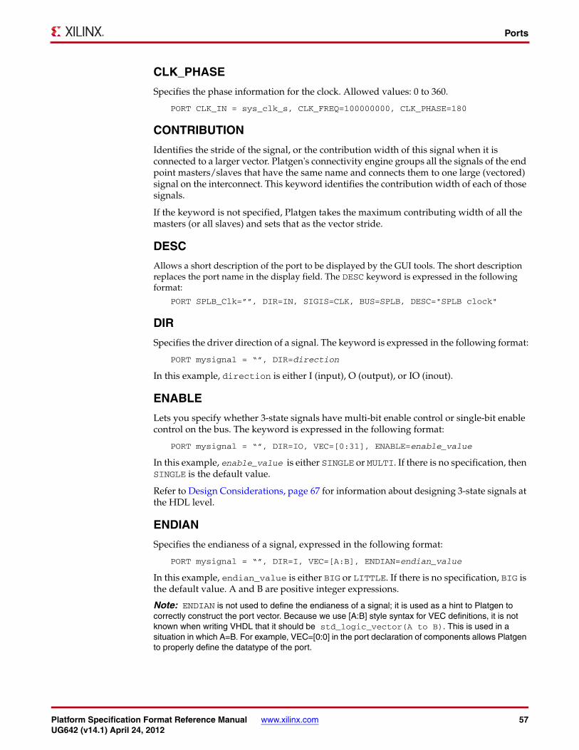
Platform Specification Format Reference Manual www.xilinx.com 57UG642 (v14.1) April 24, 2012
Ports
CLK_PHASE
Specifies the phase information for the clock. Allowed values: 0 to 360.
PORT CLK_IN = sys_clk_s, CLK_FREQ=100000000, CLK_PHASE=180
CONTRIBUTION
Identifies the stride of the signal, or the contribution width of this signal when it is connected to a larger vector. Platgen's connectivity engine groups all the signals of the end point masters/slaves that have the same name and connects them to one large (vectored) signal on the interconnect. This keyword identifies the contribution width of each of those signals.
If the keyword is not specified, Platgen takes the maximum contributing width of all the masters (or all slaves) and sets that as the vector stride.
DESC
Allows a short description of the port to be displayed by the GUI tools. The short description replaces the port name in the display field. The DESC keyword is expressed in the following format:
PORT SPLB_Clk=””, DIR=IN, SIGIS=CLK, BUS=SPLB, DESC="SPLB clock"
DIR
Specifies the driver direction of a signal. The keyword is expressed in the following format:
PORT mysignal = “”, DIR=direction
In this example, direction is either I (input), O (output), or IO (inout).
ENABLE
Lets you specify whether 3-state signals have multi-bit enable control or single-bit enable control on the bus. The keyword is expressed in the following format:
PORT mysignal = “”, DIR=IO, VEC=[0:31], ENABLE=enable_value
In this example, enable_value is either SINGLE or MULTI. If there is no specification, then SINGLE is the default value.
Refer to Design Considerations, page 67 for information about designing 3-state signals at the HDL level.
ENDIAN
Specifies the endianess of a signal, expressed in the following format:
PORT mysignal = “”, DIR=I, VEC=[A:B], ENDIAN=endian_value
In this example, endian_value is either BIG or LITTLE. If there is no specification, BIG is the default value. A and B are positive integer expressions.
Note: ENDIAN is not used to define the endianess of a signal; it is used as a hint to Platgen to correctly construct the port vector. Because we use [A:B] style syntax for VEC definitions, it is not known when writing VHDL that it should be std_logic_vector(A to B). This is used in a situation in which A=B. For example, VEC=[0:0] in the port declaration of components allows Platgen to properly define the datatype of the port.

58 www.xilinx.com Platform Specification Format Reference ManualUG642 (v14.1) April 24, 2012
Chapter 3: Microprocessor Peripheral Definition (MPD)
INITIALVAL
Specifies the signal driver value on unconnected input signals, expressed in the following format:
PORT mysignal = “”, DIR=INPUT, INITIALVAL=init_value
In this example, the init_value is either VCC or GND. If there is no specification, then GND is the default value.
INTERRUPT_PRIORITY
Defines the relative priority of interrupt signals. The keyword is expressed in the following format:
PORT Intr="", DIR=O, SENSITIVITY=EDGE_RISING, SIGIS=INTERRUPT, INTERRUPT_PRIORITY=LOW
The level is dependent upon the speed of the interface that the IP controls.
For example:
• AUART runs at default 19200 baud, which gives a byte-rate of around 2000 bytes/s.
• An Ethernet 100 runs at 100 MHz, which gives a byte-rate of 12 000 000 bytes/s.
Therefore, UART is LOW and Ethernet is HIGH.
Bus runs at 1 MHz and gives a byte-rate of 120 000 bytes/s, which would be MEDIUM. It is also dependent upon whether or not the IP has FIFO, which is a judgment that the designer must make.
IOB_STATE
Deprecated. If necessary, Platgen allows XST to infer all IOB primitives.
Used for DRC purposes to guard against specific I/O connectivity issues:
• INOUT ports must have the same port name and connector name if the pcore embeds an IOBUF. Use THREE_STATE=FALSE to check for condition (remains as a Platgen DRC).
• An INPUT port must have a connector if the pcore embeds an IBUF. Use Tcl SYSLEVEL_DRC_PROC to check the condition.
The IOB_STATE keyword identifies ports that instantiate or infer IOB primitives. The keyword is expressed in the following format:
PORT DDR_Addr = “”, DIR=OUT, VEC=[0:C_DDR_AWIDTH-1], IOB_STATE=REG
The values are BUF, INFER, or REG. The default is INFER.
When a port requires an IOB primitive (IOB_STATE=INFER), Platgen instantiates an IOB buffer. When a port has an IOB buffer (IOB_STATE=BUF) or IOB register (IOB_STATE=REG), Platgen does not instantiate an IOB primitive.
IO_IF
The I/O interface association name is formatted as follows:
PORT C405TRCCYCLE=””, DIR=O, IO_IF=trace_0, IO_IS=trace_clk

Platform Specification Format Reference Manual www.xilinx.com 59UG642 (v14.1) April 24, 2012
Ports
IO_IS
Defines an XBD relationship marker. IO_IS implies that the port can be pulled out to the FPGA boundary. Without a corresponding XBD value, the tag has no effect.
A port that has an IO_IS must also have an IO_IF association with a particular IO_INTERFACE in the MPD. An MPD could have more than one IO_INTERFACE. Therefore, a port with an IO_IS must be associated with only one of them. The IO_IS keyword is expressed in the following format:
PORT C405TRCCYCLE=””, DIR=O, IO_IF=trace_0, IO_IS=trace_clk
ISVALID
Defines the validity of a PORT to an expression. If the expression evaluates true, the PORT is included in the list of valid PORTs of the defined system for DRC processing.
If false, the PORT is not included and no DRC is performed. However, the PORT remains listed in the HDL. It is expressed in the following format:
PORT SDRAM_RAS_n = "", DIR = O, ISVALID = (C_MEM_TYPE == 2)
LONG_DESC
Allows a long description of the port to be displayed by the GUI tools. The long description allows the GUI tools to display a hover help. There is no default and the use of this keyword is formatted as follows:
PORT OPB_Clk="", DIR=I, SIGIS=CLK, BUS=SOPB, LONG_DESC="Clock from OPB"
PERMIT
Determines if BSB should specify a particular port as a top-level port in the MHS. Only those ports that have a PERMIT value of BASE_USER are connected by BSB to top-level ports. The default value is ADVANCED_USER. The PERMIT keyword is expressed in the following format:
PORT JTGC405TCK=JTGC405TCK, DIR=I, PERMIT = BASE_USER
SENSITIVITY
Specifies the interrupt sensitivity of an interrupt signal. This keyword supersedes the EDGE and LEVEL keywords. The SENSITIVITY keyword is expressed in the following format:
PORT interrupt="", DIR=O, SENSITIVITY=value, SIGIS=INTERRUPT
In this example, the value is either EDGE_FALLING, EDGE_RISING, LEVEL_HIGH, or LEVEL_LOW.

60 www.xilinx.com Platform Specification Format Reference ManualUG642 (v14.1) April 24, 2012
Chapter 3: Microprocessor Peripheral Definition (MPD)
SIGIS
The class of a signal is specified by the SIGIS keyword, which is expressed in the following format:
PORT mysig="", DIR=O, SIGIS=value
In this example, the value is CLK, INTERRUPT, or RST.. Table 3-17 describes SIGIS usage.
THREE_STATE
Enables or disables 3-state expansion. This supersedes the deprecated 3STATE keyword. The THREE_STATE keyword is expressed in the following format:
PORT PAR="", DIR=INOUT, THREE_STATE=FALSE, IOB_STATE=BUF
For output ports, the default value is FALSE. For inout ports, the default value is TRUE.
Refer to the 3-state (InOut and Output) Signals section of this chapter for information about designing 3-state signals at the HDL level.
TRI_I, TRI_O, and TRI_T
Define the associative ports of the 3-state. This directly correlates to the IOBUF UNISIM primitive where the:
• I port is represented by the TRI_O
• T port is represented by the TRI_T
• O port s represented by the TRI_I
This also directly correlates to the OBUFT UNISIM primitive where the I port is represented by the TRI_O keyword, the T port by TRI_T, and the TRI_I keyword is not defined. These properties are only valid when THREE_STATE=TRUE. The TRI_I, TRI_O, and TRI_T keywords are expressed in the following format:
PORT IPIO = ““, DIR=INOUT, TRI_T=x, TRI_O=y, TRI_T=z, THREE_STATE=TRUEPORT x = ““, DIR=OUTPORT y = ““, DIR=OUTPORT z = ““, DIR=IN
See the 3-state (InOut and Output) Signals, page 68 for information about designing 3-state signals at the HDL level.
Table 3-17: SIGIS Usage
SIGIS Usage
CLK • XPS
Displays all clock signals.
• Platgen
For all bus components, the clock signals are automatically connected to the clock input of the peripherals on the bus.
INTERRUPT • XPS
Displays all interrupt signals.
• Platgen
Encodes the priority interrupt vector
RST • XPS
Displays all reset signals.

Platform Specification Format Reference Manual www.xilinx.com 61UG642 (v14.1) April 24, 2012
Ports
VEC
Specifies the vector width of a signal, expressed in the following format:
PORT mysignal = “”, DIR=INPUT, VEC=[A:B]
A and B are positive integer expressions.
Port Naming ConventionsThis section provides naming conventions for bus interface signal names. These conventions are flexible to accommodate embedded processor systems that have more than one bus interface and more than one bus interface port per component.
The names must be HDL (VHDL or Verilog) compliant. As with any language, VHDL and Verilog have certain naming rules and conventions that you must follow.
Global Ports
The names for the global ports of a peripheral (such as clock and reset signals) are standardized. You can use any name for other global ports (such as the interrupt signal).
LMB - Clock and Reset
LMB_ClkLMB_Rst
PLB - Clock and Reset
PLB_ClkPLB_Rst
Slave DCR Ports
Naming conventions should be followed for that part of the identifier following the last underscore in the name.
DCR Slave Outputs
For interconnection to the DCR, all slaves must provide the following outputs in which <Sln> is a meaningful name or acronym for the slave output:
<Sln>_dcrDBus<Sln>_dcrAck
An additional requirement on <Sln> is that it must not contain the string DCR (upper, lower, or mixed case), so that slave outputs are not confused with bus outputs.
uart_dcrAckintc_dcrAckmemcon_dcrAck

62 www.xilinx.com Platform Specification Format Reference ManualUG642 (v14.1) April 24, 2012
Chapter 3: Microprocessor Peripheral Definition (MPD)
DCR Slave Inputs
For interconnection to the DCR, all slaves must provide the following inputs:
<nDCR>_ABus<nDCR>_Sl_DBus<nDCR>_Read<nDCR>_Write
In this example, <nDCR> is a meaningful name or acronym for the slave input. An additional requirement on <nDCR> is that the last three characters must contain the string DCR (upper, lower, or mixed case).
DCR_Sl_DBusbus1_DCR_Sl_DBus
Slave LMB Ports
Naming conventions should be followed for that part of the identifier following the last underscore in the name.
LMB Slave Outputs
For interconnection to the LMB, all slaves must provide the following outputs:
<Sln>_DBus<Sln>_Ready
In this example, <Sln> is a meaningful name or acronym for the slave output. An additional requirement on <Sln> is that it must not contain the string “LMB” (upper, lower, or mixed case), so that slave outputs are not confused with bus outputs.
d_Readyi_Ready
LMB Slave Inputs
For interconnection to the LMB, all slaves must provide the following inputs:
<nLMB>_ABus<nLMB>_ReadStrobe<nLMB>_AddrStrobe<nLMB>_WriteStrobe<nLMB>_WriteDBus<nLMB>_BE
In this example, <nLMB> is a meaningful name or acronym for the slave input. An additional requirement on <nLMB> is that the last three characters must contain the string LMB (upper, lower, or mixed case).
LMB_ABusbus1_LMB_ABus
Master PLB Ports
Naming conventions should be followed for that part of the identifier following the last underscore in the name.

Platform Specification Format Reference Manual www.xilinx.com 63UG642 (v14.1) April 24, 2012
Ports
PLB Master Outputs
For interconnection to the PLB, all masters must provide the following outputs:
<Mn>_ABus<Mn>_BE<Mn>_RNW<Mn>_abort<Mn>_busLock<Mn>_compress<Mn>_guarded<Mn>_lockErr<Mn>_MSize<Mn>_ordered<Mn>_priority<Mn>_rdBurst<Mn>_request<Mn>_size<Mn>_type<Mn>_wrBurst<Mn>_wrDBus
In this example, <Mn> is a meaningful name or acronym for the master output. An additional requirement for <Mn> is that it must not contain the string PLB (upper, lower, or mixed case), so that master outputs are not confused with bus outputs.
iM_requestbridge_requesto2ob_request
PLB Master Inputs
For interconnection to the PLB, all masters must provide the following inputs:
<nPLB>_MAddrAck<nPLB>_MBusy<nPLB>_MErr<nPLB>_MRdBTerm<nPLB>_MRdDAck<nPLB>_MRdDBus<nPLB>_MRdWdAddr<nPLB>_MRearbitrate<nPLB>_MWrBTerm<nPLB>_MWrDAck<nPLB>_MSSize
In this example, <nPLB> is a meaningful name or acronym for the master input. An additional requirement on <nPLB> is that the last three characters must contain the string PLB (upper, lower, or mixed case).
iPLB_MBusyPLB_MBusybus1_PLB_MBusy
Slave PLB Ports
Naming conventions should be followed for that part of the identifier following the last underscore in the name.

64 www.xilinx.com Platform Specification Format Reference ManualUG642 (v14.1) April 24, 2012
Chapter 3: Microprocessor Peripheral Definition (MPD)
PLB Slave Outputs
For interconnection to the PLB, all slaves must provide the following outputs:
<Sln>_addrAck<Sln>_MErr<Sln>_MBusy<Sln>_rdBTerm<Sln>_rdComp<Sln>_rdDAck<Sln>_rdDBus<Sln>_rdWdAddr<Sln>_rearbitrate<Sln>_SSize<Sln>_wait<Sln>_wrBTerm<Sln>_wrComp<Sln>_wrDAck
In this example, <Sln> is a meaningful name or acronym for the slave output. An additional requirement on <Sln> is that it must not contain the string PLB (upper, lower, or mixed case), so that slave outputs are not confused with bus outputs.
tmr_addrAck, uart_addrAck, intc_addrAck
PLB Slave Inputs
For interconnection to the PLB, all slaves must provide the following inputs:
<nPLB>_ABus<nPLB>_BE<nPLB>_PAValid<nPLB>_RNW<nPLB>_abort<nPLB>_busLock<nPLB>_compress<nPLB>_guarded<nPLB>_lockErr<nPLB>_masterID<nPLB>_MSize<nPLB>_ordered<nPLB>_pendPri<nPLB>_pendReq<nPLB>_reqPri<nPLB>_size<nPLB>_type<nPLB>_rdPrim<nPLB>_SAValid<nPLB>_wrPrim<nPLB>_wrBurst<nPLB>_wrDBus<nPLB>_rdBurst
In this example, <nPLB> is a meaningful name or acronym for the slave input. An additional requirement on <nPLB> is that the last three characters must contain the string PLB (upper, lower, or mixed case).
PLB_size, iPLB_size, dPLB_size

Platform Specification Format Reference Manual www.xilinx.com 65UG642 (v14.1) April 24, 2012
Ports
Reserved Port ConnectionsConnectivity of the DCR, LMB, OPB, and PLB buses to peripherals is done through a common set of signal connections.
Clock and Reset Ports
For interconnection to the clock and reset ports:
PORT <BUS NAME>_Clk = “”, DIR=I, SIGIS=CLKPORT <BUS NAME>_Rst = <BUS NAME>_Rst, DIR=I
The <BUS NAME> is replaced with the name of the BUS_STD in use or the name of the BUS_INTERFACE in use. Notice that the clock port has no default value. The clock port is an input to the bus that you assign in the MHS. Therefore, all peripherals on the bus must also be treated as a user input port. If a default value were given to <BUS NAME>_Clk, this would not match the clock you defined in the MHS, and the EDK tools would assume a short in the system and tie off the sourceless ports.
The reset port is an output from the bus and has a default value. All peripherals on the bus share the same default: <BUS NAME>_Rst. Your input to the bus is SYS_Rst, which has no default value.
Slave LMB Ports
For interconnection to the LMB, all slaves must provide the following connections:
PORT <Sln>_DBus = Sl_DBus, DIR=O, VEC=[0:C_LMB_DWIDTH-1], BUS=SLMBPORT <Sln>_Ready = Sl_Ready, DIR=O, BUS=SLMBPORT <nLMB>_ABus = LMB_ABus, DIR=I, VEC=[0:C_LMB_AWIDTH-1], BUS=SLMBPORT <nLMB>_ReadStrobe = LMB_ReadStrobe, DIR=I, BUS=SLMBPORT <nLMB>_AddrStrobe = LMB_AddrStrobe, DIR=I, BUS=SLMBPORT <nLMB>_WriteStrobe = LMB_WriteStrobe, DIR=I, BUS=SLMBPORT <nLMB>_WriteDBus = LMB_WriteDBus, DIR=I, VEC=[0:C_LMB_DWIDTH-1], BUS=SLMBPORT <nLMB>_BE = LMB_BE, DIR=I, VEC=[0:C_LMB_DWIDTH/8-1], BUS=SLMB
Master PLB Ports
For interconnection to the PLB, all masters must provide the following connections:
PORT <Mn>_ABus = M_ABus, DIR=O, VEC=[0:C_PLB_AWIDTH-1], BUS=MPLBPORT <Mn>_BE = M_BE, DIR=O, VEC=[0:C_PLB_DWIDTH/8-1], BUS=MPLBPORT <Mn>_RNW = M_RNW, DIR=O, BUS=MPLBPORT <Mn>_abort = M_abort, DIR=O, BUS=MPLBPORT <Mn>_busLock = M_busLock, DIR=O, BUS=MPLBPORT <Mn>_compress = M_compress, DIR=O, BUS=MPLBPORT <Mn>_guarded = M_guarded, DIR=O, BUS=MPLBPORT <Mn>_lockErr = M_lockErr, DIR=O, BUS=MPLBPORT <Mn>_MSize = M_MSize, DIR=O, VEC=[0:1], BUS=MPLBPORT <Mn>_ordered = M_ordered, DIR=O, BUS=MPLBPORT <Mn>_priority = M_priority, DIR=O, VEC=[0:1], BUS=MPLBPORT <Mn>_rdBurst = M_rdBurst, DIR=O, BUS=MPLBPORT <Mn>_request = M_request, DIR=O, BUS=MPLBPORT <Mn>_size = M_size, DIR=O, VEC=[0:3], BUS=MPLBPORT <Mn>_type = M_type, DIR=O, VEC=[0:2], BUS=MPLBPORT <Mn>_wrBurst = M_wrBurst, DIR=O, BUS=MPLBPORT <Mn>_wrDBus = M_wrDBus, DIR=O, VEC=[0:C_PLB_DWIDTH-1], BUS=MPLBPORT <nPLB>_MAddrAck = PLB_MAddrAck, DIR=I, BUS=MPLB

66 www.xilinx.com Platform Specification Format Reference ManualUG642 (v14.1) April 24, 2012
Chapter 3: Microprocessor Peripheral Definition (MPD)
PORT <nPLB>_MBusy = PLB_MBusy, DIR=I, BUS=MPLBPORT <nPLB>_MErr = PLB_MErr, DIR=I, BUS=MPLBPORT <nPLB>_MRdBTerm = PLB_MRdBTerm, DIR=I, BUS=MPLBPORT <nPLB>_MRdDAck = PLB_MRdDAck, DIR=I, BUS=MPLBPORT <nPLB>_MRdDBus = PLB_MRdDBus, DIR=I, VEC=[0:C_PLB_DWIDTH-1], BUS=MPLBPORT <nPLB>_MRdWdAddr = PLB_MRdWdAddr, DIR=I, VEC=[0:3], BUS=MPLBPORT <nPLB>_MRearbitrate = PLB_MRearbitrate, DIR=I, BUS=MPLBPORT <nPLB>_MWrBTerm = PLB_MWrBTerm, DIR=I, BUS=MPLBPORT <nPLB>_MWrDAck = PLB_MWrDAck, DIR=I, BUS=MPLBPORT <nPLB>_MSSize = PLB_MSSize, DIR=I, VEC=[0:1], BUS=MPLB
Slave PLB Ports
For interconnection to the PLB, all slaves must provide the following connections:
PORT <Sln>_addrAck = Sl_addrAck, DIR=O, BUS=SPLBPORT <Sln>_MErr = Sl_MErr, DIR=O, VEC=[0:C_NUM_MASTERS-1], BUS=SPLBPORT <Sln>_MBusy = Sl_MBusy, DIR=O, VEC=[0:C_NUM_MASTERS-1], BUS=SPLBPORT <Sln>_rdBTerm = Sl_rdBTerm, DIR=O, BUS=SPLBPORT <Sln>_rdComp = Sl_rdComp, DIR=O, BUS=SPLBPORT <Sln>_rdDAck = Sl_rdDAck, DIR=O, BUS=SPLBPORT <Sln>_rdDBus = Sl_rdDBus, DIR=O, VEC=[0:C_PLB_DWIDTH-1],BUS=SPLBPORT <Sln>_rdWdAddr = Sl_rdWdAddr, DIR=O, VEC=[0:3], BUS=SPLBPORT <Sln>_rearbitrate = Sl_rearbitrate, DIR=O, BUS=SPLBPORT <Sln>_SSize = Sl_SSize, DIR=O, VEC=[0:1], BUS=SPLBPORT <Sln>_wait = Sl_wait, DIR=O, BUS=SPLBPORT <Sln>_wrBTerm = Sl_wrBTerm, DIR=O, BUS=SPLBPORT <Sln>_wrComp = Sl_wrComp, DIR=O, BUS=SPLBPORT <Sln>_wrDAck = Sl_wrDAck, DIR=O, BUS=SPLBPORT <nPLB>_ABus = PLB_ABus, DIR=I, VEC=[0:C_PLB_AWIDTH-1], BUS=SPLBPORT <nPLB>_BE = PLB_BE, DIR=I, VEC=[0:(C_PLB_DWIDTH/8)-1], BUS=SPLBPORT <nPLB>_PAValid = PLB_PAValid, DIR=I, BUS=SPLBPORT <nPLB>_RNW = PLB_RNW, DIR=I, BUS=SPLBPORT <nPLB>_abort = PLB_abort, DIR=I, BUS=SPLBPORT <nPLB>_busLock = PLB_busLock, DIR=I, BUS=SPLBPORT <nPLB>_compress = PLB_compress, DIR=I, BUS=SPLBPORT <nPLB>_guarded = PLB_guarded, DIR=I, BUS=SPLBPORT <nPLB>_lockErr = PLB_lockErr, DIR=I, BUS=SPLBPORT <nPLB>_masterID = PLB_masterID, DIR=I,VEC=[0:C_PLB_MID_WIDTH-1], BUS=SPLBPORT <nPLB>_MSize = PLB_MSize, DIR=I, VEC=[0:1], BUS=SPLBPORT <nPLB>_ordered = PLB_ordered, DIR=I, BUS=SPLBPORT <nPLB>_pendPri = PLB_pendPri, DIR=I, VEC=[0:1], BUS=SPLBPORT <nPLB>_pendReq = PLB_pendReq, DIR=I, BUS=SPLBPORT <nPLB>_reqPri = PLB_reqPri, DIR=I, VEC=[0:1], BUS=SPLBPORT <nPLB>_size = PLB_size, DIR=I, VEC=[0:3], BUS=SPLBPORT <nPLB>_type = PLB_type, DIR=I, VEC=[0:2], BUS=SPLBPORT <nPLB>_rdPrim = PLB_rdPrim, DIR=I, BUS=SPLBPORT <nPLB>_SAValid = PLB_SAValid, DIR=I, BUS=SPLBPORT <nPLB>_wrPrim = PLB_wrPrim, DIR=I, BUS=SPLBPORT <nPLB>_wrBurst = PLB_wrBurst, DIR=I, BUS=SPLBPORT <nPLB>_wrDBus = PLB_wrDBus, DIR=I, VEC=[0:C_PLB_DWIDTH-1],BUS=SPLBPORT <nPLB>_rdBurst = PLB_rdBurst, DIR=I, BUS=SPLB

Platform Specification Format Reference Manual www.xilinx.com 67UG642 (v14.1) April 24, 2012
Design Considerations
Design Considerations
Unconnected PortsUnconnected output ports are assigned open, and unconnected input ports are either set to GND or VCC.
An unconnected port is identified as an empty double-quote (““) string.
The EDK tools resolve the driver value on unconnected input ports by the INITIALVAL keyword, using this format:
PORT mysignal = “”, DIR=OUTPUT
Scalable DatapathUsing an MPD keyword declaration, you can automatically scale the datapath width. Bus expressions are evaluated as arithmetic equation, and are formatted as follows.
PORT name = default_connection, VEC=[A:B]
In this example, A and B are positive integer expressions.
MPD Example
The following is an example MPD file:
BEGIN my_peripheral# Generics for vhdl or parameters for verilogPARAMETER C_BASEADDR = 0xB00000, DT=std_logic_vector(0 to 31)PARAMETER C_MY_PERIPH_AWIDTH = 17, DT=integer# Global portsPORT OPB_Clk = “”, DIR=IPORT OPB_Rst = “”, DIR=I# My peripheral signalsPORT MY_ADDR = “”, DIR=O, VEC=[0:C_MY_PERIPH_AWIDTH-1]# OPB signals..END
To change this default behavior, use the ENDIAN keyword, which should be formatted as follows:
PORT mysignal = “”, DIR=I, VEC=[0:0], ENDIAN=LITTLE
This builds the VHDL equivalent:
mysignal: in std_logic_vector(0 downto 0);
Interrupt Signals
Interrupt signals are identified by the SIGIS=INTERRUPT name-value.

68 www.xilinx.com Platform Specification Format Reference ManualUG642 (v14.1) April 24, 2012
Chapter 3: Microprocessor Peripheral Definition (MPD)
3-state (InOut and Output) Signals
Note: Read this section if you want the EDK tools to infer a 3-state port for your output or in/out port.
A system on a programmable device design methodology follows these general guidelines:
• Submodule port driver directions (modes) should be either IN or OUT
• Top-level module/entity is allowed to have ports of mode INOUT
The drive direction (mode) of a port impacts the partitioning of a design. The mode of a port must propagate through all levels of hierarchy, with the result that if the top-level requests an inout port, then a low-level module must provide an inout port for connectivity. Alternatively, at the top-level hierarchy, the user must describe the inout drive direction to connect the lower-level, unidirectional ports of the submodule to the top-level bidirectional inout port.
This methodology fits into an FGPA architecture because 3-state buffers are only available as an IOBUF primitive in the IOB cell.
A reduced implementation is a tri_output, which Platgen maps to the OBUFT primitive. 3-states in the CLB do not exist; the synthesis tool translates the 3-state logic to MUXes.
An abstract inout port on the MPD is defined for connectivity purposes. The abstract port allows a user to connect the top-level inout port to the lower-level abstract inout port without changing the partition or interface of the submodule in hardware.
At the MHS/MPD level, there is an abstract inout port in the MPD file that allows a connection through the IOBUF to the top-level inout port declaration in the MHS file. This corresponds to the usage of defining an inout port at the top level and preserving unidirectional ports at the lower level.
Figure 3-1 shows an IPIO port that is an abstract port of drive direction inout.X-Ref Target - Figure 3-1
Note: The 3-state enable is active-low. This allows a direct connection to the OBUFT or the IOBUF without an inversion of the 3-state enable port.
This port in Figure 3-1 is not listed on the port interface of the hardware module or entity, as demonstrated in the following code examples.
In the MPD file, an abstract inout port is identified by the inout direction mode and THREE_STATE=TRUE without defined TRI_I, TRI_O, and TRI_T keywords. In this case, the abstract inout port name must share a common basename across the basename_I, basename_O, and basename_T ports on the port interface of the hardware module or entity.
In Figure 3-1, the basename is IPIO. Platgen expands the inout port in the MPD file to _I, _O, and _T ports in the port interface declaration of the HDL file. This method does not allow the individual ports that construct the abstract port to be listed in the MPD.
Figure 3-1: OBUF Implementation
X9877
MY_IP
IOBUF
T
I
O
O
O
I
IPIO_T
IPIO_O IPIO
IPIO_I

Platform Specification Format Reference Manual www.xilinx.com 69UG642 (v14.1) April 24, 2012
Design Considerations
In the MPD file, an abstract inout port is identified by the inout or output (tri-output) direction mode and THREE_STATE=TRUE with defined TRI_I, TRI_O, and TRI_T keywords.
In this case, the abstract inout port name allows free connection to the individual ports that construct the abstract port. The abstract inout port or output (tri-output) is freely named. This method does allow the individual ports that construct the abstract port to be listed in the MPD.
3-state (InOut) With Single-Bit Enable
The following examples include a 3-state port with a single-bit enable.
VHDL Example
entity tri_state_single isgeneric (C_WIDTH: integer:= 9);port (
-- 3-state signalIPIO_I: in std_logic_vector(0 to C_WIDTH-1);IPIO_O: out std_logic_vector(0 to C_WIDTH-1);IPIO_T: out std_logic);
end entity tri_state_single;
MPD Example
BEGIN tri_state_singleOPTION IPTYPE=IPPARAMETER C_WIDTH=9, DT=integerPORT IPIO = “”, DIR=INOUT, VEC=[0:C_WIDTH-1], ENABLE=SINGLE, THREE_STATE=TRUEEND
3-state (InOut) With Multi-Bit Enable
The following examples include a 3-state port with a multi-bit enable.
VHDL Example
entity tri_state_multi isgeneric (C_WIDTH: integer:= 9);port (
-- 3-state signalIPIO_I: in std_logic_vector(0 to C_WIDTH-1);IPIO_O: out std_logic_vector(0 to C_WIDTH-1);IPIO_T: out std_logic_vector(0 to C_WIDTH-1));
end entity tri_state_multi;
MPD Example
BEGIN tri_state_multiOPTION IPTYPE=IPPARAMETER C_WIDTH = 9, DT=integerPORT IPIO = “”, DIR=INOUT, VEC=[0:C_WIDTH-1], ENABLE=MULTI, THREE_STATE=TRUEEND

70 www.xilinx.com Platform Specification Format Reference ManualUG642 (v14.1) April 24, 2012
Chapter 3: Microprocessor Peripheral Definition (MPD)
3-state (In/Out) With Single-Bit Enable With Freely Named Ports
The following examples include a 3-state port with a single-bit enable with freely named ports.
VHDL Example
entity tri_state_single isgeneric (C_WIDTH: integer:= 9);port (
-- 3-state signalITRI: in std_logic_vector(0 to C_WIDTH-1);OTRI: out std_logic_vector(0 to C_WIDTH-1);TTRI: out std_logic);
end entity tri_state_single;
MPD Example
BEGIN tri_state_singleOPTION IPTYPE=IPPARAMETER C_WIDTH=9, DT=integerPORT IPIO=“”, DIR=IO,VEC=[0:C_WIDTH-1],THREE_STATE=TRUE, TRI_I=ITRI, TRI_O=OTRI, TRI_T=TTRIPORT ITRI=””, DIR=I, VEC=[0:C_WIDTH-1]PORT OTRI=””, DIR=O, VEC=[0:C_WIDTH-1]PORT TTRI=””, DIR=IEND
3-state (InOut) With Multi-Bit Enable With Freely Named Ports
These examples show a 3-state port with a multi-bit enable with freely-named ports.
VHDL Example
entity tri_state_single isgeneric (C_WIDTH: integer:= 9);port (
-- 3-state signalITRI: in std_logic_vector(0 to C_WIDTH-1);OTRI: out std_logic_vector(0 to C_WIDTH-1);TTRI: out std_logic(0 to C_WIDTH-1));
end entity tri_state_single;
MPD Example
BEGIN tri_state_singleOPTION IPTYPE=IPPARAMETER C_W=9, DT=integerPORT IPIO=“”, DIR=IO, VEC=[0:C_WIDTH-1], ENABLE=MULTI, TRI_I=ITRI, TRI_O=OTRI, TRI_T=TTRIPORT ITRI=””, DIR=I, VEC=[0:C_WIDTH-1]PORT OTRI=””, DIR=O, VEC=[0:C_WIDTH-1]PORT TTRI=””, DIR=I, VEC=[0:C_WIDTH-1]END

Platform Specification Format Reference Manual www.xilinx.com 71UG642 (v14.1) April 24, 2012
Design Considerations
3-state (Output) With Single-Bit Enable
These examples include a 3-state output port with a single-bit enable.
VHDL Example
entity tri_state_output_single isgeneric (C_WIDTH: integer:= 9);port (-- 3-state signalIPO_O: out std_logic_vector(0 to C_WIDTH-1);IPO_T: out std_logic);end entity tri_state_output_single;
MPD Example
BEGIN tri_state_output_singleOPTION IPTYPE=IPPARAMETER C_WIDTH=9, DT=integerPORT IPO = “”, DIR=O, VEC=[0:C_WIDTH-1], ENABLE=SINGLE, THREE_STATE=TRUEEND
3-state (Output) With Multi-Bit Enable
These examples include a 3-state output port with a multi-bit enable.
VHDL Example
entity tri_state_output_multi isgeneric (C_WIDTH: integer:= 9);port (-- 3-state signalIPO_O: out std_logic_vector(0 to C_WIDTH-1);IPO_T: out std_logic_vector(0 to C_WIDTH-1));end entity tri_state_output_multi;
MPD Example
BEGIN tri_state_output_multiOPTION IPTYPE=IPPARAMETER C_WIDTH = 9, DT=integerPORT IPO = “”, DIR=O, VEC=[0:C_WIDTH-1], ENABLE=MULTI, THREE_STATE=TRUEEND
3-state (Output) With Single-Bit Enable With Freely Named Ports
These examples include a 3-state output port with a single-bit enable and with freely named ports.
VHDL Example
entity tri_state_output_single isgeneric (C_WIDTH: integer:= 9);port (-- 3-state signalOTRI: out std_logic_vector(0 to C_WIDTH-1);TTRI: out std_logic);end entity tri_state_output_single;

72 www.xilinx.com Platform Specification Format Reference ManualUG642 (v14.1) April 24, 2012
Chapter 3: Microprocessor Peripheral Definition (MPD)
MPD Example
BEGIN tri_state_output_singleOPTION IPTYPE=IPPARAMETER C_WIDTH=9, DT=integerPORT IPO=“”, DIR=O,VEC=[0:C_WIDTH-1],THREE_STATE=TRUE, TRI_O=OTRI, TRI_T=TTRIPORT OTRI=””, DIR=O, VEC=[0:C_WIDTH-1]PORT TTRI=””, DIR=IEND
3-state (Output) With Multi-Bit Enable With Freely Named Ports
These examples show a 3-state output port with a multi-bit enable and with freely named ports.
VHDL Example
entity tri_state_output_single isgeneric (C_WIDTH: integer:= 9);port (-- 3-state signalOTRI: out std_logic_vector(0 to C_WIDTH-1);TTRI: out std_logic(0 to C_WIDTH-1));end entity tri_state_output_single;
MPD Example
BEGIN tri_state_output_singleOPTION IPTYPE=IPPARAMETER C_W=9, DT=integerPORT IPO=“”, DIR=O, VEC=[0:C_WIDTH-1], ENABLE=MULTI, TRI_O=OTRI, TRI_T=TTRIPORT OTRI=””, DIR=O, VEC=[0:C_WIDTH-1]PORT TTRI=””, DIR=I, VEC=[0:C_WIDTH-1]END

Platform Specification Format Reference Manual www.xilinx.com 73UG642 (v14.1) April 24, 2012
Chapter 4
Peripheral Analyze Order (PAO)
A PAO (Peripheral Analyze Order) file contains a list of HDL files that are needed for synthesis and defines the analyze order for compilation.
If the STYLE option in the MPD file has a value of MIX or HDL, the core has a PAO file.
PAO Format
FormatUse the following format:
tooltarget libraryname <relative path from library>/filename[.v|.vhd] hdlang
• The tooltarget specifies the tool target. Valid values are lib, simlib, synlib, and vlgincdir. Files specified with lib are used for both synthesis and simulation. Files specified with simlib are for behavioral simulation only. The vlgincdir defines the relative path of the Verilog Include directories. Files specified with synlib are only for synthesis.
• The libraryname specifies the library that contains the file. All of the files for the IP should use the IP as the library name. The library name is given with the version appended. For example, for version 1.00.a the library name is libraryname_v1_00_a. The name is in lower case.
• The filename specifies the file name. The filename optionally can have a file extension. If the file extension is omitted, then for VHDL, the .vhd extension is added; for Verilog, the .v extension is added. If the MPD file specifies OPTION HDL=BOTH, then extensions cannot be specified.
The filename can specify the keyword all in place of a file name. This causes all the files from the given library to be included. Do not use the keyword all if you are referring to the same library to which the PAO belongs. Any sub-library that is referenced using the all keyword must have a valid PAO file associated with it. The name is in lower-case.
Note: The filename can optionally specify subfolders relative to the path of the hdl/verilog or hdl/vhdl folder.
• The hdllang specifies the language of the file name. Valid values are verilog and vhdl. This field is required when OPTION HDL=MIXED is used. If the language is not specified, the OPTION HDL value determines the value of this field.This field cannot be specified for OPTION HDL=BOTH. This field is ignored if the keyword all is used. In that particular case, the PAO of the sub-library determines the language of each of the files included from that library.

74 www.xilinx.com Platform Specification Format Reference ManualUG642 (v14.1) April 24, 2012
Chapter 4: Peripheral Analyze Order (PAO)
CommentsYou can insert comments without disrupting processing. The following are guidelines for inserting comments:
• Precede comments with the pound sign (#)
• Comments can continue to the end of the line
• Comments can be anywhere on the line
Verilog Include DirectoriesYou must use relative paths to allow project maneuverability from development platform to development platform. Use the `include compiler directive in your Verilog HDL files to insert the contents of an entire file.
The following is an example Verilog HDL file:
`include “global_consts.v”`include “pcore_v1_00_a/hdl/verilog/consts.v"
By default, all known EDK repositories are automatically included to the calls that process Verilog:
<proj_dir>/pcores$XILINX_EDK/hw/XilinxBFMinterface/pcores$XILINX_EDK/hw/XilinxProcessorIPLib/pcores$XILINX_EDK/hw/XilinxReferenceDesigns/pcores
You need only specify include paths that are not default. User-specified paths have a higher precedence over the default paths.
FormatUse the following format:
vlgincdir <library> <relative path from library>
PAO ExampleThe following is an example of a VHDL PAO file:
lib common_v1_00_a common_types_pkg.vhdlib common_v1_00_a pselect.vhdlib opb_gpio_v1_00_a gpio_corelib opb_gpio_v1_00_a opb_gpio
The following is an example of a MIXED PAO file:
lib libname_v2_00_a mysubfolder1/file1.vhd vhdllib ipname_v1_00_a file2.v veriloglib ipname_v1_00_a file3.vhd vhdlsimlib ipname_v1_00_a simfile.v verilogsynlib ipname_v1_00_a synfile.vhd vhdl

Platform Specification Format Reference Manual www.xilinx.com 75UG642 (v14.1) April 24, 2012
Chapter 5
Microprocessor-IP User Interface (MUI)A Microprocessor-IP User Interface (MUI) file is a configuration file in eXtended Markup Language (XML) format. You can use an MUI file to create a custom configuration dialog box for IP cores that are not already available in the XPS software.
Note: You should have some knowledge of XML in order to create an MUI file.
Types of IP Dialog BoxesThere are two types of dialog boxes, each of which gives you a different level of complexity for core configuration. The two types of dialog boxes are Simple and Basic.
Simple IP Dialog BoxA simple dialog box shows a core configuration based on the MPD parameters. It shows the MPD parameters in a simple format without tool tips or other advanced features that MUI files provide. In this type of dialog box, no extra data file is needed. The Simple dialog box is based on the MPD file in the absence of an MUI. For most cores without advanced features, using the MPD description is adequate.X-Ref Target - Figure 5-1
Figure 5-1: Simple Dialog Box

76 www.xilinx.com Platform Specification Format Reference ManualUG642 (v14.1) April 24, 2012
Chapter 5: Microprocessor-IP User Interface (MUI)
Basic IP Dialog BoxBasic dialog boxes offer more features than a simple dialog box provides, including:
• Plain-English text labels for parameters
• Tool tips
• Separate configuration tabs
• Parameter groups within a tab
It also has type checking to guarantee correct-by-construction.
To develop a Basic configuration dialog box, you can use any text editor to create the MUI file. After writing the MUI file, save it in the /data directory of a processor core. XPS will render the MUI file into a configuration dialog box during runtime.
Figure 5-2 shows an example of a Basic IP dialog box.X-Ref Target - Figure 5-2
Figure 5-2: Basic IP Dialog Box Example

Platform Specification Format Reference Manual www.xilinx.com 77UG642 (v14.1) April 24, 2012
Organization of a MUI File
Organization of a MUI FileAn MUI file is in a typical XML format. It comprises three sections: an external document type definition (DTD) reference, an internal entity definition section, and a set of entity references.
DTD Reference SectionThe DTD file ipdialog.dtd must be defined for all MUI files. This file is located in <EDK_Install>/hw/XilinxProcessorIPLib/pcores.
When referencing this file in the MUI file, use a relative path to the file. For MUI files that are correctly placed in the /data subfolder of the pcore, the relative link is:
../../ipdialog.dtd
For a MUI file to be correctly rendered into a dialog box, it must be well formed and DTD-compliant. The DTD file contains the schema of the MUI file and some common parameter definitions, such as those for PLBv46 and AXI.
Internal Entity Definition SectionSome common bus-related parameters are already defined in the external DTD file. However, core-specific parameters must be defined individually. You can use the internal entity definition section to list those parameter definitions.
Core-specific parameters comprise the following components:
• <key> – the name of the parameter in the MPD. The value of this tag must match the name in the MPD file.
• <label> – a short text description. This tag defines the label for the parameter in the dialog box.
• <tip> – a tool tip. This information displays in a pop-up window in the dialog box when the mouse is held over the parameter name. Content is not required for this tag.
The following example from the AXI_GPIO core shows an example of the beginning of an MUI file, including the required DTD reference along with a parameter definition. Figure 5-3 shows its rendering in the interface.
<?xml version="1.0" encoding="ISO-8859-1"?><!DOCTYPE doc SYSTEM "../../ipdialog.dtd" [ <!ENTITY C_GPIO_WIDTH ' <widget id="C_GPIO_WIDTH"> <key>C_GPIO_WIDTH</key> <label>GPIO Data Channel Width</label> <tip></tip> </widget> '> ... ]>

78 www.xilinx.com Platform Specification Format Reference ManualUG642 (v14.1) April 24, 2012
Chapter 5: Microprocessor-IP User Interface (MUI)
Entity Reference SectionThe entity reference section lists the parameters and organizes them hierarchically. Each parameter in the MPD file must have a corresponding entry in the MUI file.
The elements in the hierarchy are:
• <doc> element
This element, at the top of the hierarchy, is the root element. All of the interface parameters are listed in this element.
• <view> element
This element, in the second level of the hierarchy, identifies the tab name. In a basic dialog box, there are typically two <view> elements. The first is the User tab, which lists parameters that are specific to the IP, such as the input or output of a GPIO core. The other lists system properties such as addresses and bus parameters (width, P2P/shared topography).
For each tab, you can further divide parameters into groups. The view element should have an id attribute with a value of either User or System. There should be only one view for each id. The text in the <display> element defines the text of the correlating tab in the GUI.
X-Ref Target - Figure 5-3
Figure 5-3: Internal Entity Example

Platform Specification Format Reference Manual www.xilinx.com 79UG642 (v14.1) April 24, 2012
Organization of a MUI File
• <group> element
A group associates parameters so that they can be displayed as related in the IP configuration dialog box on the associated view (tab). Each group must have a unique id attribute. The display> element text defines the label of the corresponding group.
Note: To make some parameters invisible to the user, you can use a "hidden" group.
• <item> element
This element is a reference to the entity (parameter) definition.
Example
A partial example of the entities for a basic dialog box based on the AXI GPIO core is shown here. Most of the entity descriptions have been removed to simplify the example.
<?xml version="1.0" encoding="ISO-8859-1"?><!DOCTYPE doc SYSTEM "../../ipdialog.dtd" [ <!ENTITY C_GPIO_WIDTH ' <widget id="C_GPIO_WIDTH"> <key>C_GPIO_WIDTH</key> <label>GPIO Data Channel Width</label> <tip></tip> </widget> '> <!ENTITY C_ALL_INPUTS ' <widget id="C_ALL_INPUTS"> <key>C_ALL_INPUTS</key> <label>Channel 1 is Input Only </label> <tip></tip> </widget> '>
X-Ref Target - Figure 5-4
Figure 5-4: Example Output of Elements

80 www.xilinx.com Platform Specification Format Reference ManualUG642 (v14.1) April 24, 2012
Chapter 5: Microprocessor-IP User Interface (MUI)
... ]>
<doc> <view id="User"> <display>User</display> <group id="Common"> <display>Common</display> <item>&C_INTERRUPT_PRESENT;</item> <item>&C_IS_DUAL;</item> </group> <group id="Channel_1"> <display>Channel 1</display> <item>&C_GPIO_WIDTH;</item> <item>&C_DOUT_DEFAULT;</item> <item>&C_TRI_DEFAULT;</item> <item>&C_ALL_INPUTS;</item> </group> </view> <view id="System"> <display>System</display> <group id="Addresses"> <display>Addresses</display> <item>&C_BASEADDR;</item> <item>&C_HIGHADDR;</item> </group> <group id="Hidden"> <display>Hidden</display> <item>&C_FAMILY;</item> </group> </view></doc>
Validating the MUI FileThe MUI file must be consistent with the other files, especially the MPD file. It must be:
• Well-formed as an XML file.
• DTD-valid with regard to the ipdialog.dtd file.
• Consistent with the MPD file in the same directory. That is, there should be the same parameters references in the MUI file that directly correspond to the parameters in the MPD file.

Platform Specification Format Reference Manual www.xilinx.com 81UG642 (v14.1) April 24, 2012
Chapter 6
Black-Box Definition (BBD)
The Black Box Definition (BBD) file manages the file locations of optimized hardware netlists for the black-box sections of your peripheral design.
The STYLE option in the MPD with the values of MIX, or BLACKBOX, identify the core as having a BBD file.
BBD FormatThe BBD format is a look-up table that lists netlist files. The first line is the header of the look-up table. There can be as many entries as necessary in the header to make a selection. Header entries are available only if defined as MPD parameters. The last column of the table must be the FILES column.
The netlist directory in the IP directory can have its own underlying directory structure because the BBD file manages the relative file locations.
Each file is listed with the file extension of the hardware implementation netlist. Because implementation netlists have multiple file extensions (such as .edn, .edf, .edo, .ngo), it is important to identify the format.
In addition to netlist files listed in this chapter, BBD could also list .mif files. During netlist generation, while the netlist files are copied to implementation folder, Platgen copies the .mif files to the synthesis folder.
CommentsYou can insert comments without disrupting processing. The following are guidelines for inserting comments:
• Precede comments with the pound sign (#).
• Comments can continue to the end of the line.
• Comments can be anywhere on the line.
ListsIf you have multiple hardware implementation netlists, then use a comma to separate each individual netlist in the list.
Common Repository LibrarySupport for relative paths to a common repository library is specified with the (:) syntax. For example, ddr_common is used to release netlists for the DDR for both opb_ddr and plb_ddr.

82 www.xilinx.com Platform Specification Format Reference ManualUG642 (v14.1) April 24, 2012
Chapter 6: Black-Box Definition (BBD)
BBD Examples
File Selection Without OptionsThe following is an example of a file selection without options. The NGC netlist is copied into your implementation directory, regardless of specific options set on the core.
FILESblackbox.ngc
Multiple File Selections Without OptionsThe following is an example of multiple file selections without options. The set of NGC netlists are copied into the your implementation directory regardless of specific options set on the core.
FILESblackbox1.ngc, blackbox2.ngc, blackbox3.edn
File Selection With OptionsThe following is an example of a file selection with options. The specific EDIF netlist is copied into your implementation directory dependent on the C_FAMILY and C_BUS_CONFIG parameters set on the core.
C_FAMILY C_BUS_CONFIG FILESvirtex 1 virtex/ip1.edfvirtex 2 virtex/ip2.edfvirtexe 1 virtex/ip1.edfvirtexe 2 virtex/ip2.edfvirtex2 1 virtex2/ip1.edfvirtex2 2 virtex2/ip2.edfvirtex2p 1 virtex2/ip1.edfvirtex2p 2 virtex2/ip2.edf
File Selection With Common Repository LibraryThe following is an example of a file selection with a common repository library. The following example illustrates that the netlist ddr_v1_00_b_virtex2_async_fifo.edn is delivered from ddr_v1_00_b repository library.
C_FAMILY FILESvirtex2 ddr_v1_00_b:ddr_v1_00_b_virtex2_async_fifo.ednvirtex2p ddr_v1_00_b:ddr_v1_00_b_virtex2_async_fifo.edn
Platform Specification Format Reference Manual www.xilinx.com 83UG642 (v14.1) April 24, 2012
Chapter 7
Microprocessor Software Specification (MSS)
This chapter describes theMicroprocessor Software Specification (MSS) format.
OverviewYou supply an MSS file as an input to the Library Generator (Libgen). The MSS file contains directives for customizing operating systems (OSs), libraries, and drivers.
Note: The RevUp tool provides a way to convert the old MSS format to the new one used in this version of the EDK tools. For more information see Chapter 9, “Format Revision Tool,” in the Embedded System Tools Reference Manual (UG111). A link to that document is provided in Appendix A, Additional Resources.
MSS FormatYou supply an MSS file as an input to the Library Generator (Libgen). An MSS file is case insensitive and any reference to a file name or instance name in the MSS file is also case sensitive.
Comments can be specified anywhere in the file. A pound (#) character denotes the beginning of a comment, and all characters after it, right up to the end of the line, are ignored. All white spaces are also ignored and carriage returns act as sentence delimiters.

84 www.xilinx.com Platform Specification Format Reference ManualUG642 (v14.1) April 24, 2012
Chapter 7: Microprocessor Software Specification (MSS)
MSS KeywordsThe keywords that are used in an MSS file are as follows:
BEGIN
The keyword begins a driver, processor, or file system definition block. BEGIN should be followed by the driver, processor or filesys keywords.
END
This keyword signifies the end of a definition block.
PARAMETER
The MSS file has a simple name = value format for statements. The PARAMETER keyword is required before NAME and VALUE pairs. The format for assigning a value to a parameter is parameter name = value. If the parameter is within a BEGIN-END block, it is a local assignment; otherwise it is a global (system level) assignment.
RequirementsThe MSS file has a dependency on the MHS file. This dependency has to be specified as a command line option to Libgen using the -mhs option. Refer to the “Library Generator” chapter in the Embedded System Tools Reference Manual for more information. (For a link to the manual, see Appendix A, Additional Resources.) There is a resulting dependency on hardware for the software flow. Refer to Chapter 2, Microprocessor Hardware Specification (MHS) for more information on hardware configuration.
Prior to the EDK 6.1 release, this dependency was specified in the MSS file as parameter HW_SPEC_FILE = file_name.mhs. This parameter was deprecated in the EDK6.1 release, because the MHS file is given as a command line option to the Libgen tool.
The syntax of various files that the embedded development tools use is described by the Platform Specification Format (PSF). The current PSF version is 2.1.0. The MSS file should also contain version information in the form of parameter Version = 2.1.0, which represents the PSF version 2.1.0.

Platform Specification Format Reference Manual www.xilinx.com 85UG642 (v14.1) April 24, 2012
MSS Format
MSS ExampleAn example MSS file is as follows:
parameter VERSION = 2.1.0
BEGIN OSparameter PROC_INSTANCE = my_microblazeparameter OS_NAME = standaloneparameter OS_VER = 1.00.aparameter STDIN = my_uartlite_1parameter STDOUT = my_uartlite_1END
BEGIN PROCESSORparameter HW_INSTANCE = my_microblazeparameter DRIVER_NAME = cpuparameter DRIVER_VER = 1.00.aparameter XMDSTUB_PERIPHERAL = my_jtagEND
BEGIN OSparameter PROC_INSTANCE = my_ppcparameter OS_NAME = standaloneparameter OS_VER = 1.00.aparameter STDIN = my_uartlite_2parameter STDOUT = my_uartlite_2END
BEGIN PROCESSORparameter HW_INSTANCE = my_ppcparameter DRIVER_NAME = cpu_ppc405parameter DRIVER_VER = 1.00.aEND
BEGIN DRIVERparameter HW_INSTANCE = my_intcparameter DRIVER_NAME = intcparameter DRIVER_VER = 1.00.aEND
BEGIN DRIVERparameter HW_INSTANCE = my_uartlite_1parameter DRIVER_VER = 1.00.aparameter DRIVER_NAME = uartliteparameter INT_HANDLER = uart_1_handler, INT_PORT = InterruptEND
BEGIN DRIVERparameter HW_INSTANCE = my_uartlite_2parameter DRIVER_VER = 1.00.aparameter DRIVER_NAME = uartliteparameter INT_HANDLER = uart_2_handler, INT_PORT = InterruptEND
BEGIN DRIVERparameter HW_INSTANCE = my_timebase_wdtparameter DRIVER_VER = 1.00.aparameter DRIVER_NAME = timebase_wdt

86 www.xilinx.com Platform Specification Format Reference ManualUG642 (v14.1) April 24, 2012
Chapter 7: Microprocessor Software Specification (MSS)
parameter INT_HANDLER=my_timebase_hndl, INT_PORT = Timebase_Interruptparameter INT_HANDLER=my_timebase_hndl, INT_PORT = WDT_InterruptEND
BEGIN LIBRARYparameter LIBRARY_NAME = XilMfsparameter LIBRARY_VER = 1.00.aparameter NUMBYTES = 100000parameter BASE_ADDRESS = 0x80f00000END
BEGIN DRIVERparameter HW_INSTANCE = my_jtagparameter DRIVER_NAME = uartliteparameter DRIVER_VER = 1.00.aparameter INT_HANDLER = jtag_uart_handler, INT_PORT = InterruptEND
Global ParametersThese parameters are system-specific parameters and do not relate to a particular driver, file system, or library.
PSF VersionThis option specifies the PSF version of the MSS file. This option is mandatory, and is formatted as:
parameter VERSION = 2.1.0
Parameter INT_HANDLERThis option defines the interrupt handler software routine for an external interrupt port given in the MHS file, and is formatted as:
parameter INT_HANDLER = my_int_handl, INT_PORT = Interrupt
The external interrupt port that raises the interrupt is specified after the attribute as shown in the INT_PORT keyword. This port should match the port name (not the signal name) specified in the MHS file as a global external port.
Instance-Specific ParametersThese parameters are OS-, processor-, driver-, or library-specific. The parameters must be within a BEGIN and END block.

Platform Specification Format Reference Manual www.xilinx.com 87UG642 (v14.1) April 24, 2012
Instance-Specific Parameters
OS, Driver, Library, and Processor Block Parameters SummaryThe following list shows the parameters that can be used in OS, driver, library and processor blocks.
OS, Driver, Library, and Processor Block Parameters Definitions
PROC_INSTANCE
This option is required for the OS associated with a processor instances specified in the MHS file, and is formatted as:
parameter PROC_INSTANCE = instance_name
All OSs in EDK require processor instances to be associated with the OSs. The instance name that is given must match the name specified in the MHS file.
HW_INSTANCE
This option is required for drivers associated with peripheral instances specified in the MHS file and is formatted as:
parameter HW_INSTANCE = instance_name
All drivers in EDK require instances to be associated with the drivers. Even a processor definition block should refer to the processor instance. The instance name that is given must match the name specified in the MHS file.
OS_NAME
This option is needed for processor instances that have OSs associated with them and is formatted as:
parameter OS_NAME = standalone
Library Generator copies the OS directory specified to OUTPUT_DIR/processor_instance_name/libsrc directory and compiles the OS sources using makefiles provided. See the “Library Generator” chapter in the Embedded System Tools Reference Manual for more information. For a link to the manual, see the MSS Format, page 83.
OS_VER
The OS version is set using the OSVER option and is formatted as:
parameter OS_VER = 1.00.a
This version is specified in the following format: x.yz.a, where x,y and z are digits, and a is a character. This is translated to the OS directory searched by Libgen as follows:
USER_PROJECT/bsp/OS_NAME_vx_yz_a
XILINX_EDK/sw/lib/bsp/OS_NAME_vx_yz_a
PROC_INSTANCE
HW_INSTANCE
OS_NAME
OS_VER
DRIVER_NAME
DRIVER_VER
INT_HANDLER
LIBRARY_NAME
LIBRARY_VER

88 www.xilinx.com Platform Specification Format Reference ManualUG642 (v14.1) April 24, 2012
Chapter 7: Microprocessor Software Specification (MSS)
The MLD (Microprocessor Library Definition) files Libgen needs for each OS should be named OS_NAME_v2_1_0.mld and should be present in a subdirectory data/ within the driver directory. Refer to Chapter 8, Microprocessor Library Definition (MLD) for more information.
DRIVER_NAME
This option is needed for peripherals that have drivers associated with them and is formatted as:
parameter DRIVER_NAME = uartlite
Library Generator copies the driver directory specified to OUTPUT_DIR/processor_instance_name/libsrc directory and compiles the drivers using makefiles provided. Refer to the “Library Generator” chapter in the Embedded System Tools Reference Manual, for more information.
DRIVER_VER
The driver version is set using the DRIVER_VER option, and is formatted as:
parameter DRIVER_VER = 1.00.a
This version is specified in the following format: x.yz.a, where x,y and z are digits, and a is a character. This is translated to the driver directory searched by Libgen as follows:
• <USER_PROJECT>/drivers/DRIVER_NAME_vx_yz_a
• <USER_PROJECT>/pcores/DRIVER_NAME_vx_yz_a
• XILINX_EDK/sw/XilinxProcessorIPLib/drivers/DRIVER_NAME_vx_yz_a
The MDD (Microprocessor Driver Definition) files needed by Libgen for each driver should be named DRIVER_NAME_v2_1_0.mdd and should be present in a subdirectory data/ within the driver directory. Refer to Chapter 9, Microprocessor Driver Definition (MDD), for more information.
INT_HANDLER
This option defines the interrupt handler software routine for an interrupt port of the peripheral and is formatted as:
parameter INT_HANDLER = my_int_handl, INT_PORT = Interrupt
The interrupt port of the peripheral instance that raises the interrupt is specified after the attribute as shown with the INT_PORT keyword. This port should match the port name (and not the signal name) specified in the MHS file for that peripheral instance.
LIBRARY_NAME
This option is needed for libraries, and is formatted as:
parameter LIBRARY_NAME = xilmfs
Library Generator copies the library directory specified in the OUTPUT_DIR/processor_instance_name/libsrc directory and compiles the libraries using makefiles provided. See the “Library Generator” chapter in the Embedded System Tools Reference Manual (UG111), for more information.

Platform Specification Format Reference Manual www.xilinx.com 89UG642 (v14.1) April 24, 2012
Instance-Specific Parameters
LIBRARY_VER
The library version is set using the LIBRARY_VER option and is formatted as:
parameter LIBRARY_VER = 1.00.a
This version is specified in the following format: x.yz.a, where x,y and z are digits, and a is a character. This is translated to the library directory searched by Libgen as follows:
• <USER_PROJECT>/sw_services/LIBRARY_NAME_vx_yz_a
• XILINX_EDK/sw/lib/sw_services/LIBRARY_NAME_vx_yz_a
The MLD (Microprocessor Library Definition) files needed by Libgen for each library should be named LIBRARY_NAME_v_2_1_0.mld and should be present in a subdirectory data/ within the library directory. See Chapter 8, Microprocessor Library Definition (MLD) for more information.
MDD/MLD Specific ParametersParameters specified in the MDD/MLD file can be overwritten in the MSS file and formatted as
parameter PARAM_NAME = PARAM_VALUE
See Chapter 8, Microprocessor Library Definition (MLD) and Chapter 9, Microprocessor Driver Definition (MDD) for more information.
OS-Specific Parameters SummaryThe following list identifies all the parameters that can be specified only in an OS definition block.
STDIN
Identify the standard input device with the STDIN option, which is formatted as:.
parameter STDIN = instance_name
STDOUT
Identify the standard output device with the STDOUT option, which is formatted as:
parameter STDOUT = instance_name
Example: MSS Snippet Showing OS Options
BEGIN OSparameter PROC_INSTANCE = my_microblazeparameter OS_NAME = standaloneparameter OS_VER = 1.00.aparameter STDIN = my_uartlite_1parameter STDOUT = my_uartlite_1END

90 www.xilinx.com Platform Specification Format Reference ManualUG642 (v14.1) April 24, 2012
Chapter 7: Microprocessor Software Specification (MSS)
Processor-Specific Parameter SummaryFollowing is a list of all of the parameters that can be specified only in a processor definition block.
Processor-Specific Parameter Definitions
XMDSTUB_PERIPHERAL
The peripheral that is used to handle the XMDStub should be specified in the XMDSTUB_PERIPHERAL option. This is useful for the MicroBlaze™ processor only, and is formatted as follows:
parameter XMDSTUB_PERIPHERAL = instance_name
COMPILER
This option specifies the compiler used for compiling drivers and libraries. The compiler defaults to mb-gcc or powerpc-eabi-gcc depending on whether the drivers are part of the MicroBlaze™ processor or PowerPC® processor instance. Any other compatible compiler can be specified as an option, and should be formatted as follows:
parameter COMPILER = dcc
This example denotes the Diab compiler as the compiler to be used for drivers and libraries.
ARCHIVER
This option specifies the utility to be used for archiving object files into libraries. The archiver defaults to mb-ar or powerpc-eabi-ar depending on whether or not the drivers are part of the MicroBlaze or PowerPC processor instance. Any other compatible archiver can be specified as an option, and should be formatted as follows:
parameter ARCHIVER = ar
This example denotes the archiver ar to be used for drivers and libraries.
COMPILER_FLAGS
This option specifies compiler flags to be used for compiling drivers and libraries. If the option is not specified, Libgen automatically uses platform and processor-specific options. This option should not be specified in the MSS file if the standard compilers and archivers in EDK are used. The COMPILER_FLAGS option can be defined in the MSS if there is a need for custom compiler flags that override Libgen-generated flags. The EXTRA_COMPILER_FLAGS option is recommended if compiler flags must be appended to the ones Libgen already generates. Format this option as follows:
parameter COMPILER_FLAGS = ““
XMDSTUB_PERIPHERAL
COMPILER
ARCHIVER
COMPILER_FLAGS
EXTRA_COMPILER_FLAGS

Platform Specification Format Reference Manual www.xilinx.com 91UG642 (v14.1) April 24, 2012
Instance-Specific Parameters
EXTRA_COMPILER_FLAGS
This option can be used whenever custom compiler flags need to be used in addition to the automatically generated compiler flags, and should be formatted as follows:
parameter EXTRA_COMPILER_FLAGS = -g
This example specifies that the drivers and libraries must be compiled with debugging symbols in addition to the Libgen generated COMPILER_FLAGS.
Example MSS Snippet Showing Processor Options
BEGIN PROCESSORparameter HW_INSTANCE = my_microblazeparameter DRIVER_NAME = cpuparameter DRIVER_VER = 1.00.aparameter DEFAULT_INIT = xmdstubparameter XMDSTUB_PERIPHERAL = my_jtagparameter STDIN = my_uartlite_1parameter STDOUT = my_uartlite_1parameter COMPILER = mb-gccparameter ARCHIVER = mb-arparameter EXTRA_COMPILER_FLAGS = -g -O0parameter OS = standaloneEND
92 www.xilinx.com Platform Specification Format Reference ManualUG642 (v14.1) April 24, 2012
Chapter 7: Microprocessor Software Specification (MSS)

Platform Specification Format Reference Manual www.xilinx.com 93UG642 (v14.1) April 24, 2012
Chapter 8
Microprocessor Library Definition (MLD)
This chapter describes the Microprocessor Library Definition (MLD) format, Platform Specification Format 2.1.0.
OverviewAn MLD file contains directives for customizing software libraries and generating Board Support Packages (BSP) for Operating Systems (OS). This document describes the MLD format and the parameters that can be used to customize libraries and OSs. It is recommended that you read this document to become familiar with user-written libraries and OSs that must be configured by the Libgen tool.
RequirementsEach OS and library has an MLD file and a Tcl (Tool Command Language) file associated with it. The MLD file is used by the Tcl file to customize the OS or library, depending on different options in the MSS file. For more information on the MSS file format, see Chapter 7, Microprocessor Software Specification (MSS).
The OS and library source files and the MLD file for each OS and library must be located at specific directories if Libgen is to find the files and libraries. Refer to the “Library Generator” chapter in the Embedded System Tools Reference Manual, for a list of directories to be searched for OSs and libraries. A link to the Embedded System Tools Reference Manual (UG111) is provided in Appendix A, Additional Resources.
Library Definition FilesLibrary Definition involves defining Data Definition (MLD) and a Data Generation (Tcl) files.
Data Definition File
The MLD file (named as <library_name>_v2_1_0.mld or <os_name>_v2_1_0.mld) contains the configurable parameters. A detailed description of the various parameters and the MLD format is described in MLD Parameter Description Section, page 98.
Data Generation File
The second file (named as <library_name>_v2_1_0.tcl or <os_name>_v2_1_0.tcl, with the filename being the same as the MLD filename) uses the parameters configured in the MSS file for the OS or library to generate data.

94 www.xilinx.com Platform Specification Format Reference ManualUG642 (v14.1) April 24, 2012
Chapter 8: Microprocessor Library Definition (MLD)
Data generated includes, but is not limited to, generation of header files, C files, running DRCs for the OS or library and generating executables. The Tcl file includes procedures that are called by the Libgen tool at various stages of its execution. Various procedures in a Tcl file include: DRC (the name of the DRC given in the MLD file); generate (Libgen defined procedure) called after OS and library files are copied; post_generate (Libgen defined procedure) called after generate has been called on all OSs, drivers, and libraries; and execs_generate (a Libgen-defined procedure) called after the BSPs, libraries, and drivers have been generated. For more information on the workings of the Libgen tool refer to the “Library Generator” chapter in the Embedded System Tools Reference Manual (UG111). A link to this book is provided in the Appendix A, Additional Resources.
Note: An OS/library does not require a data generation file (Tcl file).
MLD Format SpecificationThe MLD format specification involves the MLD file Format specification and the Tcl file Format specification. The following subsections describe the MLD.
MLD File Format SpecificationThe MLD file format specification involves the description of parameters defined in the Parameter Description section.
Parameter Description Section
This data section describes configurable parameters in an OS/library. The format used to describe this section is discussed in MLD Parameter Description Section, page 98.
Tcl File Format SpecificationEach OS and library has a Tcl file associated with the MLD file. This Tcl file has the following sections:
DRC Section
This section contains Tcl routines that validate your OS and library parameters for consistency.
Generation Section
This section contains Tcl routines that generate the configuration header and C files based on the library parameters.

Platform Specification Format Reference Manual www.xilinx.com 95UG642 (v14.1) April 24, 2012
MLD Format Specification
ExamplesThis section explains the MLD format through an example MLD file and its corresponding Tcl file.
Example: MLD File for a Library
The following is an example of an MLD file for the xilmfs library:
OPTION psf_version = 2.1.0 ;
OPTION is a keyword identified by the Libgen tool. The option name following the OPTION keyword is a directive to the Libgen tool to do a specific action.
The psf_version of the MLD file is defined to be 2.1 in this example. This is the only option that can occur before a BEGIN LIBRARY construct now.
BEGIN LIBRARY xilmfs
The BEGIN LIBRARY construct defines the start of a library named xilmfs.
OPTION DRC = mfs_drc ; OPTION COPYFILES = all;
The COPYFILES option indicates the files to be copied for the library. The DRC option specifies the name of the Tcl procedure that the tool invokes while processing this library. The mfs_drc is the Tcl procedure in the xilmfs_v2_1_0.tcl file that would be invoked by Libgen while processing the xilmfs library.
PARAM NAME = numbytes, DESC = "Number of Bytes”, TYPE = int, DEFAULT = 100000, DRC = drc_numbytes ; PARAM NAME = base_address, DESC = "Base Address", TYPE = int, DEFAULT = 0x10000, DRC = drc_base_address ; PARAM NAME = init_type, DESC = "Init Type", TYPE = enum, VALUES = ("New file system"=MFSINIT_NEW, "MFS Image"=MFSINIT_IMAGE, "ROM Image"=MFSINIT_ROM_IMAGE), DEFAULT = MFSINIT_NEW ; PARAM NAME = need_utils, DESC = "Need additional Utilities?", TYPE = bool, DEFAULT = false ;
PARAM defines a library parameter that can be configured. Each PARAM has the following properties associated with it, whose meaning is self-explanatory: NAME, DESC, TYPE, DEFAULT, RANGE, DRC. The property VALUES defines the list of possible values associated with an ENUM type.
BEGIN INTERFACE file PROPERTY HEADER="xilmfs.h" ; FUNCTION NAME=open, VALUE=mfs_file_open ; FUNCTION NAME=close, VALUE=mfs_file_close ; FUNCTION NAME=read, VALUE=mfs_file_read ; FUNCTION NAME=write, VALUE=mfs_file_write ; FUNCTION NAME=lseek, VALUE=mfs_file_lseek ; END INTERFACE
An Interface contains a list of standard functions. A library defining an interface should have values for the list of standard functions. It must also specify a header file where all the function prototypes are defined.
PROPERTY defines the properties associated with the construct defined in the BEGIN construct. Here HEADER is a property with value “xilmfs.h”, defined by the file interface. FUNCTION defines a function supported by the interface.

96 www.xilinx.com Platform Specification Format Reference ManualUG642 (v14.1) April 24, 2012
Chapter 8: Microprocessor Library Definition (MLD)
The open, close, read, write, and lseek functions of the file interface have the values mfs_file_open, mfs_file_close, mfs_file_read, mfs_file_write, and mfs_file_lseek. These functions are defined in the header file xilmfs.h.
BEGIN INTERFACE filesystem
BEGIN INTERFACE defines an interface the library supports. Here file is the name of the interface.
PROPERTY HEADER=”xilmfs.h” ; FUNCTION NAME=cd, VALUE=mfs_change_dir ; FUNCTION NAME=opendir, VALUE=mfs_dir_open ; FUNCTION NAME=closedir, VALUE=mfs_dir_close ; FUNCTION NAME=readdir, VALUE=mfs_dir_read ; FUNCTION NAME=deletedir, VALUE=mfs_delete_dir ; FUNCTION NAME=pwd, VALUE=mfs_get_current_dir_name ; FUNCTION NAME=rename, VALUE=mfs_rename_file ; FUNCTION NAME=exists, VALUE=mfs_exists_file ; FUNCTION NAME=delete, VALUE=mfs_delete_file ; END INTERFACE
END LIBRARY
END is used with the construct name that was used in the BEGIN statement. Here END is used with INTERFACE and LIBRARY constructs to indicate the end of each of INTERFACE and LIBRARY constructs.
Example: Tcl File of a Library
The following is the xilmfs_v2_1_0.tcl file corresponding the xilmfs_v2_1_0.mld file described in the previous section. The mfs_drc procedure would be invoked by Libgen for the xilmfs library while running DRCs for libraries. The generate routine generates constants in a header file and a c file for xilmfs library based on the library definition segment in the MSS file.
proc mfs_drc {lib_handle} { puts "MFS DRC ..."}proc mfs_open_include_file {file_name} { set filename [file join "../../include/" $file_name] if {[file exists $filename]} {
set config_inc [open $filename a] } else {
set config_inc [open $filename a]xprint_generated_header $config_inc "MFS Parameters"
} return $config_inc}proc generate {lib_handle} {
puts "MFS generate ..." file copy "src/xilmfs.h" "../../include/xilmfs.h" set conffile [mfs_open_include_file "mfs_config.h"] puts $conffile "#ifndef _MFS_CONFIG_H" puts $conffile "#define _MFS_CONFIG_H" set need_utils [xget_value $lib_handle "PARAMETER" "need_utils"] puts $conffile "#include <xilmfs.h>" set value [xget_value $lib_handle "PARAMETER" "numbytes"] puts $conffile "#define MFS_NUMBYTES $value" set value [xget_value $lib_handle "PARAMETER" "base_address"]

Platform Specification Format Reference Manual www.xilinx.com 97UG642 (v14.1) April 24, 2012
MLD Format Specification
Example: MLD File for an OS
An example of an MLD file for the standalone OS is given below:
OPTION psf_version = 2.1.0 ;
OPTION is a keyword identified by the Libgen tool. The option name following the OPTION keyword is a directive to the Libgen tool to do a specific action. Here the psf_version of the MLD file is defined to be 2.1. This is the only option that can occur before a BEGIN OS construct at this time.
BEGIN OS standalone
The BEGIN OS construct defines the start of an OS named standalone.
OPTION DESC = “Generate standalone BSP”;OPTION COPYFILES = all;
The DESC option gives a description of the MLD. The COPYFILES option indicates the files to be copied for the OS.
PARAM NAME = stdin, DESC = "stdin peripheral ", TYPE = peripheral_instance, REQUIRES_INTERFACE = stdin, DEFAULT = none; PARAM NAME = stdout, DESC = "stdout peripheral ", TYPE = peripheral_instance, REQUIRES_INTERFACE = stdout, DEFAULT = none ; PARAM NAME = need_xilmalloc, DESC = "Need xil_malloc?", TYPE = bool, DEFAULT = false ;
PARAM defines an OS parameter that can be configured. Each PARAM has the following, associated properties: NAME, DESC, TYPE, DEFAULT, RANGE, DRC. The property VALUES defines the list of possible values associated with an ENUM type.
END OS
END is used with the construct name that was used in the BEGIN statement. Here END is used with OS to indicate the end of OS construct.
Example: Tcl File of an OS
The following is the standalone_v2_1_0.tcl file corresponding to the standalone_v2_1_0.mld file described in the previous section.The generate routine generates constants in a header file and a c file for xilmfs library based on the library definition segment in the MSS file.
proc generate {os_handle} {global env
set need_config_file "false"
#Copy over the right set of files as src based on processor type set prochandle [xget_processor]set proctype [xget_value $prochandle "OPTION" "IPNAME"]set mbsrcdir "./src/microblaze"set ppcsrcdir "./src/ppc405"switch $proctype {"microblaze" { foreach entry [glob -nocomplain [file join $mbsrcdir *]] {file copy -force $entry "./src/"
}set need_config_file "true”

98 www.xilinx.com Platform Specification Format Reference ManualUG642 (v14.1) April 24, 2012
Chapter 8: Microprocessor Library Definition (MLD)
}"ppc405" {foreach entry [glob -nocomplain [file join $ppcsrcdir *]] {file copy -force $entry "./src/"
}}"default" {puts "unknown processor type\n"}}
# Remove microblaze and ppc405 directories...file delete -force $mbsrcdirfile delete -force $ppcsrcdir
# Handle stdin and stdoutxhandle_stdin $os_handlexhandle_stdout $os_handle
# Create config file for microblaze interrupt handlingif {[string compare -nocase $need_config_file "true"] == 0} {xhandle_mb_interrupts
}
# Generate xil_malloc.h if requiredset xil_malloc [xget_value $os_handle "PARAMETER" "need_xil_malloc"]if {[string compare -nocase $xil_malloc "true"] == 0} {xcreate_xil_malloc_config_file
}}
MLD Parameter Description SectionThis section gives a detailed description of the constructs used in the MLD file.
Conventions[] Denotes optional values.
<> Value substituted by the MLD writer.
CommentsComments can be specified anywhere in the file. A “#” character denotes the beginning of a comment and all characters after the “#” right up to the end of the line are ignored. All white spaces are also ignored and semi-colons with carriage returns act as sentence delimiters.
OS or Library DefinitionThe OS or library section includes the OS or library name, options, dependencies, and other global parameters, using the following syntax:
OPTION psf_version = <psf version number> BEGIN LIBRARY/OS <library/os name> [OPTION drc = <global drc name>] [OPTION depends = <list of directories>] [OPTION help = <help file>][OPTION requires_interface = <list of interface names>]
Platform Specification Format Reference Manual www.xilinx.com 99UG642 (v14.1) April 24, 2012
MLD Parameter Description Section
PARAM <parameter description> [BEGIN CATEGORY <name of category> <category description>
END CATEGORY] BEGIN INTERFACE <interface name>
....... END INTERFACE]
END LIBRARY/OS
MLD or MDD Keyword SummaryThe keywords that are used in an MLD or MDD file are as follows:
MLD or MDD Keyword DefinitionsThe keywords that are used in an MLD or MDD file are as follows:
Note: The keyword ARRAY can only be used in MLD files. It is not allowed for MDD files.
BEGIN
The BEGIN keyword begins one of the following: os, library, driver, block, category, interface, array.
END
The END keyword signifies the end of a definition block.
PSF_VERSION
Specifies the PSF version of the library.
DRC
Specifies the DRC function name. This is the global DRC function, which is called by the GUI configuration tool or the command-line Libgen tool. This DRC function is called once you enter all the parameters and MLD or MDD writers can verify that a valid OS, library, or driver can be generated with the given parameters.
BEGIN
END
PSF_VERSION
DRC
OPTION
COPYFILES
DEPENDS
SUPPORTED_PERIPHERALS
LIBRARY_STATE
APP_COMPILER_FLAGS
APP_LINKER_FLAGS
OS_STATE
BSP
REQUIRES_INTERFACE
REQUIRES_OS
HELP
DEP
INTERFACE
HEADER
FUNCTION
CATEGORY
PARAM
PROPERTY
NAME
DESC
TYPE
DEFAULT
GUI_PERMIT
ARRAY

100 www.xilinx.com Platform Specification Format Reference ManualUG642 (v14.1) April 24, 2012
Chapter 8: Microprocessor Library Definition (MLD)
OPTION
Specifies that the name following the keyword option is an option to the Libgen or GUI tools.
COPYFILES
Specifies the files to be copied for the OS, library, or driver. If ALL is used, then Libgen copies all the OS, library, or driver files.
DEPENDS
Specifies the list of directories that needs to be compiled before the OS or library is built.
SUPPORTED_PERIPHERALS
Specifies the list of peripherals supported by the OS. The values of this option can be specified as a list, or as a regular expression. For example:
option supported_peripherals = (ppc405)
Indicates that the OS supports all versions of ppc_405. Regular expressions can be used in specifying the peripherals and versions. The regular expression (RE) is constructed as follows:
Single-Character REs
- Any character that is not a special character (to be defined) matches itself.
- A backslash (followed by any special character) matches the literal character itself. That is, this “escapes” the special character.
- The special characters are: + * ? . [ ] ^ $
- The period (.) matches any character except the new line. For example, .umpty matches either "Humpty" or “Dumpty.”
- A set of characters enclosed in brackets ([]) is a one-character RE that matches any of the characters in that set. For example, [akm] matches either an "a", "k", or "m". A range of characters can be indicated with a dash. For example, [a-z] matches any lower-case letter. However, if the first character of the set is the caret (^), then the RE matches any character except those in the set. It does not match the empty string. Example: [^akm] matches any character except "a", "k", or "m". The caret loses its special meaning if it is not the first character of the set.

Platform Specification Format Reference Manual www.xilinx.com 101UG642 (v14.1) April 24, 2012
MLD Parameter Description Section
Multi-Character REs
- A single-character RE followed by an asterisk (*) matches zero or more occurrences of the RE. Thus, [a-z]* matches zero or more lower-case characters.
- A single-character RE followed by a plus (+) matches one or more occurrences of the RE. Thus, [a-z]+ matches one or more lower-case characters.
- A question mark (?) is an optional element. The preceeding RE can occur zero or once in the string -- no more. Thus, xy?z matches either xyz or xz.
- The concatenation of REs is a RE that matches the corresponding concatenation of strings. For example, [A-Z][a-z]* matches any capitalized word.
- For example, the following matches an version of the ppc405 and ppc405_virtex4:
OPTION supported_peripherals = (ppc405_v[0-9]+_[1-9][0-9]_[a-z]ppc405_virtex4);
LIBRARY_STATE
Specifies the state of the library. Following is the list of values that can be assigned to LIBRARY_STATE:
ACTIVE
An active library. By default the value of LIBRARY_STATE is ACTIVE.
DEPRECATED
This library is deprecated.
OBSOLETE
This library is obsolete and will not be recognized by any tools. Tools error out on an obsolete library and a new library should be used instead.
APP_COMPILER_FLAGS
This option specifies what compiler flags must be added to the application when using this library. For example:
OPTION APP_COMPILER_FLAGS = “-D MYLIBRARY”
The GUI tools can use this option value to automatically set compiler flags automatically for an application.
APP_LINKER_FLAGS
This option specifies that linker flags must be added to the application when using a particular library or OS. For example:
OPTION APP_LINKER_FLAGS = “-lxilkernel”
The GUI tools can use this value to set linker flags automatically for an application.

102 www.xilinx.com Platform Specification Format Reference ManualUG642 (v14.1) April 24, 2012
Chapter 8: Microprocessor Library Definition (MLD)
BSP
Specifies a boolean keyword option that can be provided in the MLD file to identify when an OS component is to be treated as a third party BSP. For example
OPTION BSP = true;
This indicates that the SDK tools will offer this OS component as a board support package. If set to false, the component is handled as a native embedded software platform.
OS_STATE
Specifies the state of the operating system (OS). Following is the list of values that can be assigned to OS_STATE:
ACTIVE
This is an active OS. By default the value of OS_STATE is ACTIVE.
DEPRECATED
This OS is deprecated.
OBSOLETE
This OS is obsolete and will not be recognized by the tools. Tools error out on an obsolete OS and a new OS must be specified.
REQUIRES_INTERFACE
Specifies the interfaces that must be provided by other OSs, libraries, or drivers in the system.
REQUIRES_OS
Specifies the list of OSs with which the specified library will work. For example:
OPTION REQUIRES_OS = (standalone xilkernel_v4_[0-9][0-9]_[a-z])
The GUI tools use this option value to determine which libraries are offered for a given operating system choice. The values in the list can be regular expressions as shown in the example.
Note: This option must be used on libraries only.
HELP
Specifies the HELP file that describes the OS, library, or driver.
DEP
Specifies the condition that must be satisfied before processing an entity. For example to include a parameter that is dependent on another parameter (defined as a DEP, for dependent, condition), the DEP condition should be satisfied. Conditions of the form (operand1 OP operand2) are the only supported conditions.

Platform Specification Format Reference Manual www.xilinx.com 103UG642 (v14.1) April 24, 2012
MLD Parameter Description Section
INTERFACE
Specifies the interfaces implemented by this OS, library, or driver. It describes the interface functions and header files used by the library/driver.
BEGIN INTERFACE <interface name> OPTION DEP=<list of dependencies>; PROPERTY HEADER=<name of header file where the function is declared>;FUNCTION NAME=<name of interface function>, VALUE=<function name of
library/driver implementation> ;END INTERFACE
HEADER
Specifies the HEADER file in which the interface functions would be defined.
FUNCTION
Specifies the FUNCTION implemented by the interface. This is a name-value pair in which name is the interface function name and value is the name of the function implemented by the OS, library, or driver.
CATEGORY
Defines an unconditional block. This block gets included based on the default value of the category or if included in the MSS file.
BEGIN CATEGORY <category name> PARAM name = <category name>, DESC=<param description>,
TYPE=<category type>, DEFAULT=<default>, GUI_PERMIT=<value>, DEP = <condition> OPTION DEPENDS=<list of dependencies>, DRC=<drc name>, HELP=<help
file>; < parameters or categories description>
END CATEGORY
Nested categories are not supported through the syntax that specifies them. A category is selected in a MSS file by specifying the category name as a parameter with a boolean value TRUE. A category must have a PARAM with category name.
PARAM
The MLD file has a simple name = value format for most statements. The PARAM keyword is required before every such NAME, VALUE pairs. The format for assigning a value to a parameter is param name = <name>, default = value. The PARAM keyword specifies that the parameter can be overwritten in the MSS file.
PROPERTY
Specifies the various properties of the entity defined with a BEGIN statement
NAME
Specifies the name of the entity in which it was defined. (Examples: param and property.)
DESC
Describes the entity in which it was defined. (Examples: param and property.)

104 www.xilinx.com Platform Specification Format Reference ManualUG642 (v14.1) April 24, 2012
Chapter 8: Microprocessor Library Definition (MLD)
TYPE
Specifies the type for the entity in which it was defined. (Example: param.) The following types are supported:
bool
Boolean (true or false).
int
Integer
string
String value within “ " (quotes).
enum
List of possible values that a parameter can take.
library
Specify other library that is needed for building the library/driver.
peripheral_instance
Specify other hardware drivers that is needed for building the library.
DEFAULT
Specifies the default value for the entity in which it was defined.
GUI_PERMIT
Specifies the permissions for modification of values. The following permissions exist:
NONE
The value cannot be modified at all.
ADVANCED_USER
The value can be modified by all. The SDK GUI does not display this value by default. This is displayed only for the advanced option in the GUI.
ALL_USERS
The value can be modified by all. The SDK GUI displays this value by default. This is the default value for all the values. If GUI_PERMIT = NONE, the category is always active.

Platform Specification Format Reference Manual www.xilinx.com 105UG642 (v14.1) April 24, 2012
Design Rule Check (DRC) Section
ARRAY
ARRAY can have any number of PARAMs, and only PARAMs. It cannot have CATEGORY as one of the fields of an array element. The size of the array can be defined as one of the properties of the array. An array with default values specified in the default property leads to its size property being initialized to the number of values. If there is no size property defined, a size property is created before initializing it with the default number of elements. Each parameter in the array can have a default value. In cases in which size is defined with an integer value, an array of size elements would be created wherein the value of each element would be the default value of each of the parameters.
BEGIN ARRAY <array name> PROPERTY desc = <array description> ;PROPERTY size = <size of the array>; PROPERTY default = <List of Values for each element based on the size
of the array> # array field description as parameters PARAM name = <name of parameter>, desc = "description of param”, type
= <type of param>, default = <default value> ..... END ARRAY
Design Rule Check (DRC) Sectionproc mydrc { handle } {
}
The DRC function could be any Tcl code that checks your parameters for correctness. The DRC procedures can access (read-only) the Platform Specification Format database (which Libgen builds using the MHS and the MSS files) to read the parameter values that you set. The handle is associated with the current library in the database. The DRC procedure can get the OS and library parameters from this handle. It can also get any other parameter from the database by first requesting a handle and using the handle to get the parameters.
For errors, DRC procedures call the Tcl error command error "error msg" that displays in an error dialog box.
For warnings, DRC procedures return a string value that can be printed on the console.
On success, DRC procedures return without any value.
Library Generation (Generate) Sectionproc mygenerate { handle } {
}
Generate could be any Tcl code that reads your parameters and generates configuration files for the OS or library. The configuration files can be C files, Header files, Makefiles, etc. The generate procedures can access (read-only) the Platform Specification Format database (which Libgen builds using the MHS and the MSS files) to read the parameter values of the OS or library that you set. The handle is a handle to the current OS or library in the database. The generate procedure can get the OS or library parameters from this handle. It can also get any other parameter from the database by first requesting a handle and using the handle to get the parameter.

106 www.xilinx.com Platform Specification Format Reference ManualUG642 (v14.1) April 24, 2012
Chapter 8: Microprocessor Library Definition (MLD)

Platform Specification Format Reference Manual www.xilinx.com 107UG642 (v14.1) April 24, 2012
Chapter 9
Microprocessor Driver Definition (MDD)
This chapter describes the Microprocessor Driver Definition (MDD) format, Platform Specification Format 2.1.0.
OverviewAn MDD file contains directives for customizing software drivers. This document describes the MDD format and the parameters that can be used to customize drivers. For more information on drivers, refer to the Driver Reference Guide (xilinx_drivers.htm) and/or the Device Driver Programmer Guide (xilinx_drivers_guide.pdf), both contained in your EDK installation directory under docs/usenglish. It is recommended that you refer to these documents to gain an understanding of user-written drivers that must be configured by the Libgen tool.
RequirementsEach device driver has an MDD file and a Tcl file associated with it. The MDD file is used by the Tcl file to customize the driver, depending on different options configured in the MSS file. For more information on the MSS file format, refer to Chapter 7, Microprocessor Software Specification (MSS).
The driver source files and the MDD file for each driver must be located at specific directories in order for Libgen to find the files and the drivers. Refer to the “Library Generator” chapter in the Embedded System Tools Reference Manual for a list of directories that is searched for drivers. A link to the manual is provided in the section below.
Driver Definition FilesDriver Definition involves defining a Data Definition file (MDD) and a Data Generation file (Tcl file).
• Data Definition File - The MDD file (<driver_name>_v2_1_0.mdd) contains the configurable parameters. A detailed description of the parameters and the MDD format is described in MDD Parameter Description, section of this chapter.
• Data Generation File - The second file (<driver_name>_v2_1_0.tcl, with the filename being the same as the MDD filename) uses the parameters configured in the MSS file for the driver to generate data. Data generated includes but not limited to generation of header files, C files, running DRCs for the driver and generating executables. The Tcl file includes procedures that are called by the Libgen tool at various stages of its execution.
108 www.xilinx.com Platform Specification Format Reference ManualUG642 (v14.1) April 24, 2012
Chapter 9: Microprocessor Driver Definition (MDD)
Various procedures in a Tcl file includes: the DRC (name of the DRC given in the MDD file), generate (Libgen defined procedure) called after driver files are copied, post_generate (Libgen defined procedure) called after generate has been called on all drivers and libraries, and execs_generate (Libgen defined procedure) called after the libraries and drivers have been generated. For more information on the working of the Libgen tool, refer to the “Library Generator” chapter in the Embedded System Tools Reference Manual. A link to the document is provided in Appendix A, Additional Resources.
Note: A driver does not require the data generation file (Tcl file).
MDD Format SpecificationThe MDD format specification involves the MDD file Format specification and the Tcl file Format specification which are described in the following subsections.
MDD File Format SpecificationThe MDD file format specification describes the parameters defined in the Parameter Description section. This data section describes configurable parameters in a driver. The format used to describe these parameters is discussed in the MDD Parameter Description, section of this chapter.
Tcl File Format SpecificationEach driver has a Tcl file associated with the MDD file. This Tcl file has the following sections:
DRC Section
This section contains Tcl routines that validate your driver parameters for consistency.
Generation Section
This section contains Tcl routines that generate the configuration header and C files based on the driver parameters
ExampleThis section explains the MDD format through an example of an MDD file and its corresponding Tcl file.
MDD: File Example
The following is an example of an MDD file for the uartlite driver:
OPTION psf_version = 2.1;
OPTION is a keyword identified by the Libgen tool. The option name following the OPTION keyword is a directive to the Libgen tool to do a specific action. Here the psf_version of the MDD file is defined as 2.1. This is the only option that can occur before a BEGIN DRIVER construct.
BEGIN DRIVER uartlite
Platform Specification Format Reference Manual www.xilinx.com 109UG642 (v14.1) April 24, 2012
MDD Format Specification
The BEGIN DRIVER construct defines the start of a driver named uartlite.
PARAM NAME = level, DESC = “Driver Level”, TYPE = int, DEFAULT = 0, RANGE = (0, 1);
PARAM defines a driver parameter that can be configured. Each PARAM has the following properties associated with it: NAME, DESC, TYPE, DEFAULT, RANGE.
BEGIN BLOCK, DEP = (level = 0)
BEGIN BLOCK, DEP allows conditional inclusion of a set of parameters subject to a condition fulfillmen. The condition is given by the DEP construct. Here the set of parameters defined inside the BLOCK would be processed by Libgen tool only when “level” parameter has a value 0.
OPTION DEPENDS = (common_v1_00_a);OPTION COPYFILES = (xuartlite_l.c xuartlite_l.h Makefile); OPTION DRC = uartlite_drc;
The DEPENDS option specifies that the driver depends on the sources of a directory named common_v1_00_a. The area for searching the dependent directory is decided by the Libgen tool. The COPYFILES option indicates the files to be copied for a “level” 0 uartlite driver. The DRC option specifies the name of the Tcl procedure that the tool invokes while processing this driver. The uartlite_drc is the Tcl procedure in the uartlite_v2_1_0.tcl file that would be invoked by Libgen while processing the uartlite driver.
BEGIN INTERFACE stdin
BEGIN INTERFACE defines an interface the driver supports. The interface name is stdin.
PROPERTY header = xuartlite_l.h;FUNCTION name = inbyte, value = XUartLite_RecvByte;END INTERFACE
An Interface contains a list of standard functions. A driver defining an interface should have values for the list of standard functions. It must also specify a header file in which all the function prototypes are defined.
PROPERTY defines the properties associated with the construct defined in the BEGIN construct. The header is a property with the value xuartlite_l.h, defined by the stdin interface. FUNCTION defines a function supported by the interface. The inbyte function of the stdin interface has the value XUartLite_RecvByte. This function is defined in the header file xuartlite_l.h.
BEGIN INTERFACE stdout PROPERTY header = xuartlite_l.h; FUNCTION name = outbyte, value = XUartLite_SendByte; END INTERFACEBEGIN INTERFACE stdio PROPERTY header = xuartlite_l.h; FUNCTION name = inbyte, value = XUartLite_RecvByte; FUNCTION name = outbyte, value = XUartLite_SendByte; END INTERFACEBEGIN ARRAY interrupt_handler PROPERTY desc = "Interrupt Handler Information"; PROPERTY size = 1, permit = none; PARAM name = int_handler, default = XIntc_DefaultHandler, desc = "Name of Interrupt Handler", type = string; PARAM name = int_port, default = Interrupt, desc = "Interrupt pin associated with the interrupt handler", permit = none; END ARRAY

110 www.xilinx.com Platform Specification Format Reference ManualUG642 (v14.1) April 24, 2012
Chapter 9: Microprocessor Driver Definition (MDD)
The ARRAY construct defines an array of parameters. The interrupt_handler is the name of the array. The description (DESC) of the array and the size (SIZE) are defined as properties of the array interrupt_handler. The construct GUI_PERMIT is a directive to the tool that you cannot change the size of the array. The array defines int_handler and int_port as parameters of an element of the array.
END BLOCKBEGIN BLOCK, dep = (level = 1) OPTION depends = (common_v1_00_a uartlite_vxworks5_4_v1_00_a); OPTION copyfiles = all;BEGIN ARRAY interrupt_handler PROPERTY desc = "Interrupt Handler Information"; PROPERTY size = 1, permit = none; PARAM name = int_handler, default = XUartLite_InterruptHandler, desc = "Name of Interrupt Handler", type = string; PARAM name = int_port, default = Interrupt, desc = "Interrupt pin associated with the interrupt handler", permit = none; END ARRAYPARAM name = connect_to, desc = “Connect to operationg system”, type = enum, values = {“VxWorks5_4” = VxWorks5_4, “None” = none}, default = none; END BLOCKEND DRIVER
END is used with the construct name that was used in the BEGIN statement. Here END is used with BLOCK and DRIVER constructs to indicate the end of each BLOCK and DRIVER construct.
Example: Tcl File
The following is the uartlite_v2_1_0.tcl file corresponding to the uartlite_v2_1_0.mdd file described in the previous section. The “uartlite_drc” procedure would be invoked by Libgen for the uartlite driver while running DRCs for drivers. The generate routine generates constants in a header file and a c file for uartlite driver, based on the driver definition segment in the MSS file.
proc uartlite_drc {drv_handle} {puts “UartLite DRC”
}
proc generate {drv_handle} { set level [xget_value $drv_handle "PARAMETER" "level"] if {$level == 0} { xdefine_include_file $drv_handle "xparameters.h" "XUartLite" "NUM_INSTANCES" "C_BASEADDR" "C_HIGHADDR" } if {$level == 1} { xdefine_include_file $drv_handle "xparameters.h" "XUartLite" "NUM_INSTANCES" "C_BASEADDR" "C_HIGHADDR" "DEVICE_ID" "C_BAUDRATE" "C_USE_PARITY" "C_ODD_PARITY" xdefine_config_file $drv_handle "xuartlite_g.c" "XUartLite" "DEVICE_ID" "C_BASEADDR" "C_BAUDRATE" "C_USE_PARITY" "C_ODD_PARITY" }}

Platform Specification Format Reference Manual www.xilinx.com 111UG642 (v14.1) April 24, 2012
MDD Parameter Description
MDD Parameter DescriptionThis section gives a detailed description of the constructs used in the MDD file.
Conventions[] - Denotes optional values.
<> - Value substituted by the MDD writer.
CommentsComments can be specified anywhere in the file. A pound (#) character denotes the beginning of a comment, and all characters after it, right up to the end of the line, are ignored. All white spaces are also ignored and semicolons with carriage returns act as sentence delimiters.
Driver DefinitionThe driver section includes the driver name, options, dependencies, and other global parameters, using the following syntax:
OPTION psf_version = <psf version number> BEGIN DRIVER <driver name> [OPTION drc = <global drc name>] [OPTION depends = <list of directories>] [OPTION help = <help file>][OPTION requires_interface = <list of interface names>] PARAM <parameter description> [BEGIN BLOCK,dep = <condition>
....... END BLOCK] [BEGIN INTERFACE <interface name>
....... END INTERFACE]
END DRIVER
MDD Keyword Summary
BEGIN
END
PSF_VERSION
DRC
OPTION
COPYFILES
DEPENDS
SUPPORTED_PERIPHERALS
DRIVER_STATE
REQUIRES_INTERFACE
HELP
DEP
BLOCK
INTERFACE
HEADER
FUNCTION
PARAM
PROPERTY
NAME
DESC
TYPE
DEFAULT
GUI_PERMIT

112 www.xilinx.com Platform Specification Format Reference ManualUG642 (v14.1) April 24, 2012
Chapter 9: Microprocessor Driver Definition (MDD)
MDD Keyword Definitions
BEGIN
The BEGIN keyword begins with one of the following: library, drive, block, category, or interface.
END
The END keyword signifies the end of a definition block.
PSF_VERSION
Specifies the PSF version of the library.
DRC
Specifies the DRC function name. This is the global DRC function, which is called by the GUI configuration tool or the command line Libgen tool. This DRC function is called when you enter all the parameters and the MLD or MDD writers can verify that a valid library or driver can be generated with the given parameters.
OPTION
Specifies the name following the keyword OPTION is an option to the tool Libgen. The following five Libgen options are supported: COPYFILES, DEPENDS, SUPPORTED_PERIPHERALS, and DRIVER_STATE. The following subsections describe these options.
COPYFILES
Specifies the list of files to be copied for the driver. If ALL is specified as the value, Libgen copies all the driver files.
DEPENDS
Specifies the list of directories on which a driver depends for compilation.
SUPPORTED_PERIPHERALS
Specifies the list of peripherals supported by the driver. The values of this option can be specified as a list or as a regular expression. The following example indicates that the driver supports all versions of opb_jtag_uart and the opb_uartlte_v1_00_b version:
option supported_peripherals = (xps_uartlite_v1_00_a, xps_uart16550)
Regular expressions can be used in specifying the peripherals and versions. The regular expression (RE) is constructed as follows:
Single-Character REs
Any character that is not a special character (to be defined) matches itself.
A backslash (followed by any special character) matches the literal character itself. That is, it escapes the special character.
The special characters are: + * ? . [ ] ^ $

Platform Specification Format Reference Manual www.xilinx.com 113UG642 (v14.1) April 24, 2012
MDD Parameter Description
The period matches any character except the newline. For example, .umpty matches either Humpty or Dumpty.
A set of characters enclosed in brackets ([]) is a one-character RE that matches any of the characters in that set. For example, [akm] matches an a, k, or m. A range of characters can be indicated with a dash. For example, [a-z] matches any lower-case letter. However, if the first character of the set is the caret (^), then the RE matches any character except those in the set. It does not match the empty string.
Example: [^akm] matches any character except a, k, or m. The caret loses its special meaning if it is not the first character of the set.
Multi-Character REs
A single-character RE followed by an asterisk (*) matches zero or more occurrences of the RE. Therefore, [a-z]* matches zero or more lower-case characters.
A single-character RE followed by a plus (+) matches one or more occurrences of the RE. Therefore, [a-z]+ matches one or more lower-case characters.
A question mark (?) is an optional element. The preceding RE can occur no times or one time in the string. For example, xy?z matches either xyz or xz.
The concatenation of REs is an RE that matches the corresponding concatenation of strings. For example, [A-Z][a-z]* matches any capitalized word.
The following example matches any version of xps_uartlite, xps_uart16550 and mdm.
OPTION supported_peripherals = (xps_uartlite_v[0-9]+_[1-9][0-9]_[a-z]xps_uart16550 mdm);
DRIVER_STATE
Specifies the state of the driver. The following are the list of values that can be assigned to DRIVER_STATE:
ACTIVE
This is an active driver. By default the value of DRIVER_STATE is ACTIVE.
DEPRECATED
This driver is deprecated and is scheduled to be removed.
OBSOLETE
This driver is obsolete and is not recognized by any tools. Tools error out on an obsolete driver, and a new driver should be used instead.
REQUIRES_INTERFACE
Specifies the interfaces that must be provided by other libraries or drivers in the system.
HELP
Specifies the help file that describes the library or driver.
DEP
Specifies the condition that needs to be satisfied before processing an entity. For example to enter into a BLOCK, the DEP condition should be satisfied. Conditions of the form (operand1 OP operand2) are supported.

114 www.xilinx.com Platform Specification Format Reference ManualUG642 (v14.1) April 24, 2012
Chapter 9: Microprocessor Driver Definition (MDD)
BLOCK
Specifies the block is to be entered into when the DEP condition is satisfied. Nested blocks are not supported.
INTERFACE
Specifies the interfaces implemented by this library or driver and describes the interface functions and header files used by the library or driver.
BEGIN INTERFACE <interface name> OPTION DEP=<list of dependencies>; PROPERTY HEADER=<name of header file where the function is declared>;FUNCTION NAME=<name of interface function>, VALUE=<function name of
library/driver implementation> ;END INTERFACE
HEADER
Specifies the header file in which the interface functions would be defined.
FUNCTION
Specifies the function implemented by the interface. This is a name-value pair where name is the interface function name and value is the name of the function implemented by the library or driver.
PARAM
Generally, the MLD/MDD file has a name = value format for statements. The PARAM keyword is required before every such NAME, VALUE pair. The format for assigning a value to a parameter is param name = <name>, default= value. The PARAM keyword specifies that the parameter can be overwritten in the MSS file.
PROPERTY
Specifies the various properties of the entity defined with a BEGIN statement
NAME
Specifies the name of the entity in which it was defined (example: PARAM, PROPERTY).
DESC
Describes the entity in which it was defined (example: PARAM, PROPERTY).
TYPE
Specifies the type for the entity in which it was defined (example: PARAM). The following are the supported types:
bool
Boolean (true or false)
int
Integer

Platform Specification Format Reference Manual www.xilinx.com 115UG642 (v14.1) April 24, 2012
Design Rule Check (DRC) Section
string
String value within “ " (quotes).
enum
List of possible values, that this parameter can take.
library
Specify other library that is needed for building the library or driver.
peripheral_instance
Specify other hardware drivers needed for building the library or driver. Regular expressions can be used to specify the peripheral instance. Refer to the section SUPPORTED_PERIPHERALS, page 112 for more details on regular expressions.
DEFAULT
Specifies the default value for the entity in which it was defined.
GUI_PERMIT
Specifies the permissions for modification of values. The following permissions exist:
NONE
The value cannot be modified at all.
ADVANCED_USER
The value can be modified by all. The SDK GUI does not display this value by default. It is displayed only as an advanced option in the GUI.
ALL_USERS
The value can be modified by all. The SDK GUI displays this value by default. This is the default value for all the values.
If GUI_PERMIT = NONE, the category is always active.
Design Rule Check (DRC) Sectionproc mydrc { handle }
The DRC function can be any Tcl code that checks your parameters for correctness. The DRC procedures can access (read-only) the Platform Specification Format database (built by the Libgen tool using the MHS and the MSS files) to read the parameter values you set. The "handle" is a handle to the current driver in the database. The DRC procedure can get the driver parameters from this handle. It can also get any other parameter from the database, by first requesting a handle and using the handle to get the parameters.
• For errors, DRC procedures would call the Tcl error command error "error msg" that displays in an error dialog box.
• For warnings, DRC procedures return a string value that can be printed on the console.
• On success, DRC procedures just return without any value.

116 www.xilinx.com Platform Specification Format Reference ManualUG642 (v14.1) April 24, 2012
Chapter 9: Microprocessor Driver Definition (MDD)
Driver Generation (Generate) Sectionproc mygenerate { handle }
Generate could be any Tcl code that reads your parameters and generates configuration files for the driver. The configuration files can be C files, Header files, or Makefiles.
The generate procedures can access (read-only) the Platform Specification Format database (built by the Libgen tool using the MHS and the MSS files) to read the parameter values of the driver that you set.
The handle is a handle to the current driver in the database.
The generate procedure can get the driver parameters from this handle. It can also get any other parameters from the database by requesting a handle and then using the handle to get the parameter.

Platform Specification Format Reference Manual www.xilinx.com 117UG642 (v14.1) April 24, 2012
Chapter 10
Xilinx Board Description (XBD) Format
OverviewThe Xilinx® Board Description (XBD) file defines the contents of a particular board and how it interfaces with the FPGA devices on the board.
The Base System Builder (BSB) uses XBD files as documented in this chapter for PLBv46 based system creation only.
An XBD file has the following characteristics:
• Blocks that define the FPGA interfaces supported by the board
• Each block has list of attributes, parameters and ports
• Connectivity information between different ports or modules
• UCF Constraints information for each FPGA pin
XBD SyntaxXBD file syntax is case insensitive.
Note: The current XBD version is 2.2.0. The version number is reflected in the names of the XBD files read by the EDK tools.
Comments in XBDYou can insert comments in the XBD file without disrupting processing. Use the following guidelines:
• Precede comments with the pound sign (#).
• Comments continue to the end of the line.
• Comments can be anywhere on the line.

118 www.xilinx.com Platform Specification Format Reference ManualUG642 (v14.1) April 24, 2012
Chapter 10: Xilinx Board Description (XBD) Format
Format
Module Definitions
Use the following format at the beginning of a module definition:
BEGIN <block_type_keyword>
The BEGIN keyword signifies the beginning of a new module. There are three block types currently identified in XBD files:
IO_INTERFACE
An IO_INTERFACE specifies a physical module on the board. This does not include the FPGA itself. Each IO_INTERFACE also has a reference to soft IPs that you can use on the FPGA to interface with that module on the board.
IO_ADAPTER
An IO_ADAPTER specifies any soft glue-logic that might be needed to bridge any IO_INTERFACE pins with the ports of the soft-IP used for that IO_INTERFACE.
FPGA
An FPGA block represents the FPGA itself.
Use the following format to end a module definition:
END
Assignment Commands
Each BEGIN-END block contains multiple assignment commands. An assignment command is a name-value pair and can have one of more subproperty name-value pairs associated with it.
Use the following format for assignment commands:
<command> <name> = <value> {, <subproperty_name> = <subproperty_value>}
There are three assignment commands:
ATTRIBUTE
Names of all the ATTRIBUTEs are keywords. EDK tools perform certain actions or use the value of the attribute in a particular manner. You can use the ATTRIBUTE assignment command both inside or outside a BEGIN-END block.
PARAMETER
You can use any name for a PARAMETER. PARAMETER names specify values of PARAMETERs on the IPs connected to the IO_INTERFACE. A PARAMETER can be specified inside IO_INTERFACE blocks only.
Platform Specification Format Reference Manual www.xilinx.com 119UG642 (v14.1) April 24, 2012
Global Attribute Commands
PORT
Any name can be used for a PORT. PORT names specify connectivity between modules (including the FPGA) on the board. A PORT can be specified only inside IO_INTERFACE and IO_ADAPTER blocks.
Both PARAMETERs and PORTs can have subproperties associated with them. Each subproperty is a name-value pair. You must specify subproperties on the same line as the PARAMETER or the PORT. Subproperties must be comma-separated.
XBD ExampleYour EDK installation directory contains XBD files shipped with EDK.
The board files can be found at:
$XILINX_EDK/board/Xilinx/boards/<board_name>/data/<board_name>_<version>.xbd
In the example path, <board_name> might be Xilinx_ML505, for example. The current XBD version is 2.2.0, therefore, <version> would be 2_2_0.
Global Attribute CommandsGlobal Attribute commands have the following syntax:
ATTRIBUTE <name> = <value>
Global Attribute Command Definitions
VENDOR
Specifies the name of the vendor. Tools use this attribute to sort various board files based on vendor name, using the following format:
ATTRIBUTE VENDOR= Xilinx
NAME
The NAME attribute is a string representing the name of the board. This is the name the tools display for you when they select a board. It is expressed in the following format:
ATTRIBUTE NAME= <Board Name>
REVISION
The REVISION attribute identifies the revision number of the board that the XBD file represents. You must associate every board revision with an XBD file that is dedicated to that board revision alone. Use the following format to specify the revision:
ATTRIBUTE REVISION = C
CONTACT_INFO_URL
Displays a web URL link that you can use to contact Xilinx if you need assistance. The CONTACT_INFO_URL attribute is expressed in the following format:
ATTRIBUTE CONTACT_INFO_URL = http://www.xilinx.com/support/techsup/tappinfo.htm

120 www.xilinx.com Platform Specification Format Reference ManualUG642 (v14.1) April 24, 2012
Chapter 10: Xilinx Board Description (XBD) Format
SPEC_URL
Displays a URL that takes you to the Xilinx website. The SPEC_URL attribute is expressed in the following format:
ATTRIBUTE SPEC_URL = http://www.xilinx.com
DESC
Provides a short text description of the board. Base System Builder uses the DESC attribute value and displays it in the GUI. The DESC attribute is expressed in the following format:
ATTRIBUTE DESC = some text
LONG_DESC
Specifies a long text description for the board. Base System Builder uses the LONG_DESC attribute value and displays it in the GUI. If the description string contains embedded commas, it must be enclosed in single quotes because the comma is a name-value delimiter. The LONG_DESC attribute is expressed using the following format:
ATTRIBUTE TEXT= ‘some long text which gives an idea to user about the board’
Local Attribute CommandsA local attribute is defined between a BEGIN-END block and expressed in the following format:
ATTRIBUTE <name> = <value>Local Attribute Command Definitions
INSTANCE
Distinguishes one module from another. The INSTANCE attribute is expressed in the following format:
ATTRIBUTE INSTANCE = clk_module
CORENAME
Identifies the pcore that is instantiated in the MHS to represent the IO_ADAPTER. Use the CORENAME attribute only with IO_ADAPTER blocks. The CORENAME attribute is expressed in the following format:
ATTRIBUTE CORENAME = mypcore
VERSION
Specifies the HW_VER of the pcore to be instantiated in the MHS file. Use the VERSION attribute only with IO_ADAPTER blocks. The VERSION attribute is expressed in the following format:
ATTRIBUTE VERSION= 1.00.a
IOTYPE
Specifies what type of IO_INTERFACE block is being used. Use the IOTYPE attribute to match the pcore instantiated in the MHS. There are no versions for the IO_INTERFACE type.

Platform Specification Format Reference Manual www.xilinx.com 121UG642 (v14.1) April 24, 2012
Local Parameter Commands
Any version information must be embedded in the IOTYPE string itself. Use the IOTYPE attribute with IO_INTERFACE blocks only. The IOTYPE attribute is expressed in the following format:
ATTRIBUTE IOTYPE = XIL_GPIO_V1
EXCLUSIVE
Represents a group of IO_INTERFACEs that are exclusive to each other. If you use one IO_INTERFACE in this group, you cannot use others, mainly because they share the same ports with the FPGA on the board. The EXCLUSIVE attribute is expressed in the following format:
ATTRIBUTE EXCLUSIVE = excl_group
JTAG_POSITION
Determines the position of the FPGA in the JTAG chain. Base System Builder uses this information while creating the etc/download.cmd file for the project. The JTAG_POSITION attribute is expressed in the following format:
ATTRIBUTE JTAG_POSITION = 1
Local Parameter CommandsA module can have any number of parameters. Parameters have a subproperty called IO_IS. You can use the string value of the IO_IS subproperty to match the parameter whose value is the same value of the XBD local parameter. This parameter is expressed in the following format:
PARAMETER <name> = <value> {, <subprop_name> = <subprop_value>}
Note: The C_BASEADDR and C_HIGHADDR are normally used to define the location of a peripheral in the processor memory map, as well as the size of the peripheral memory space. When used in an XBD file, only the size of the peripheral memory space is used. The absolute location of the peripheral in the processor memory map is specified by Base System Builder.
Local Parameter SubpropertiesA subproperty on a local parameter is a name-value pair. A local parameter can have any number of subproperty name-value pairs associated with it. All the subproperties have to be specified on the same line as the parameter itself. Each name-value pair is separated by a comma.
The value of the IO_IS subproperty matches parameters on the IP with the parameters on the hardware component on the board. The IO_IS subproperty is expressed in the following format:
PARAMETER MYPARAM = 3, IO_IS = myparam
MEMORY_TYPE
The only allowed value of the MEMORY_TYPE subproperty is FLASH. Use the MEMORY_TYPE subproperty on the C_BASEADDR parameter of a flash memory module only. The following is an example of MEMORY_TYPE:
PARAMETER C_BASEADDR = 0x00000000, IO_IS=C_BASEADDR, MEMORY_TYPE=FLASHPARAMETER C_HIGHADDR = 0x0003FFFF, IO_IS=C_HIGHADDR

122 www.xilinx.com Platform Specification Format Reference ManualUG642 (v14.1) April 24, 2012
Chapter 10: Xilinx Board Description (XBD) Format
RANGE
The value of the RANGE subproperty is a comma-separated list of integers, intended for use only on the clock module. These integers specify a list of possible clock frequencies on the board. The following example shows a board with two clock frequencies of 66 and 100 MHz. The default frequency that BSB will use is 100 Mhz.
PARAMETER CLK_FREQ = 100000000, IO_IS=clk_freq, RANGE=(66000000, 100000000) # 66 Mhz or 100 Mhz
VALUE_NOTE
The value of the VALUE_NOTE subproperty provides a short text description of values associated with this parameter. It is expressed in the following format:
PARAMETER RST_POLARITY = 0, IO_IS = polarity, VALUE_NOTE = Active LOW
Local Port CommandsA local port is defined between the BEGIN-END block of a module. XBD supports local ports only; global ports are not supported. There are no reserved PORT names. You can specify local ports in all three block types. Local port commands are formatted as follows:
PORT <name> = <connector_name> {,<subprop_name> = <subprop_value>}
Local Port Subproperties
Local Port Subproperty SummaryYou can associate a local port with any number of subproperty name-value pairs. All the subproperties must be specified on the same line as the port itself. Each name-value pair is separated by a comma.
Local Port Subproperty Definitions
DIR
Specifies the FPGA port direction. The allowed value is IO, which designates the port as an IO port.
INTERRUPT_PRIORITY
The value of the INTERRUPT_PRIORITY subproperty defines the priority of an interrupt source. This affects the order in which various interrupts are connected to the interrupt controller (and, consequently, their priority). Use the INTERRUPT_PRIORITY subproperty only for those signals that are marked as SIGIS=INTERRUPT. The INTERRUPT_PRIORITY subproperty is formatted as follows:
PORT Intr = CONN_Intr, IO_IS=intr, SIGIS=INTERRUPT, INTERRUPT_PRIORITY=HIGH

Platform Specification Format Reference Manual www.xilinx.com 123UG642 (v14.1) April 24, 2012
Associating IPs with IO_INTERFACE in XBD
IO_IS
The value of the IO_IS subproperty matches ports on the FPGA to ports of peripherals instantiated in the MHS file.
If the value of IO_IS on a port matches that on a port in the MPD file of the IP which, in turn, matches the IO_IF, it is considered a match. If there is a match, that particular port of the instantiated IP is defined as a global port in the MHS file and connected to this port on the board. The IO_IS value is formatted as follows:
PORT LED1 = CONN_LED1, IO_IS=gpio_io<0>, VALUE=net_vcc
SENSITIVITY
For a signal of type SIGIS=INTERRUPT, the SENSITIVITY subproperty defines the signal type to which this interrupt is sensitive.
The global port created in MHS that corresponds to this signal is marked with the SENSITIVITY property. This subproperty is formatted as follows:
PORT Intr = CONN_Intr, SIGIS=INTERRUPT, SENSITIVITY=LEVEL_HIGH
SIGIS
SIGIS is a subproperty of PORT and designates a port as an interrupt port.
UCF_NET_STRINGS
Specifies the constraints associated with the NET for this PORT. The UCF_NET_STRINGS subproperty takes as value a comma separated list of strings. Each string in the list creates a separate line in the UCF file related to that net. This subproperty is formatted as:
PORT SDRAM_BA0 = CONN_SDRAM_8Mx32BA1, UCF_NET_STRINGS=("LOC = L4", "IOSTANDARD=LVDCI_25")
The above line in an XBD file would lead to the following lines in the UCF file:
NET “CONN_SDRAM_8Mx32BA1” LOC = L4NET “CONN_SDRAM_8Mx32BA1” IOSTANDARD=LVDCI_25
INITIALVAL
A subproperty of VALUE, INITIALVAL specifies the value to which a port must be driven if there is no corresponding port on the IP core connected to the device. In this case, a top-level output port for the system is created and driven with this constant value. This subproperty is formatted as follows:
PORT LED1 = CONN_LED1, IO_IS=gpio_io<0>, INITIALVAL = VCC
Associating IPs with IO_INTERFACE in XBDAs previously described, an XBD file contains a number of BEGIN-END blocks, each corresponding to a hardware module on the board. The type of the module is specified using the attribute IOTYPE, as in the following example:
BEGIN <iotype>
The IOTYPE string is used to match an IP that can communicate with this module. Refer to Chapter 3, Microprocessor Peripheral Definition (MPD) for more information. An MPD file describes the behavior of an IP. Each IP can have a number of IO_INTERFACEs.

124 www.xilinx.com Platform Specification Format Reference ManualUG642 (v14.1) April 24, 2012
Chapter 10: Xilinx Board Description (XBD) Format
Each IO_INTERFACE has a subproperty called IOTYPE. The value of this subproperty determines whether or not an IP can communicate with a particular hardware module on the board.
For example, consider the following line in the MPD file for IP xps_ethernetlite:
IO_INTERFACE NAME = Ethernet_0, iotype = XIL_Ethernet_V1
This IO_INTERFACE indicates that this particular IP can communicate with a module of type Ethernet.
Similarly, the XBD file for any board that has an Ethernet module should define a block as follows:
BEGIN IO_INTERFACEATTRIBUTE INSTANCE = myEthernetATTRIBUTE IOTYPE = XIL_Ethernet_V1PARAMETER ...PORT ...
END
When tools try to find an IP that can communicate with this module on the board, they search for MPDs that have an IO_INTERFACE with IOTYPE and that match the IOTYPE of the IO_INTERFACE module in the XBD file. If there are several such IPs, users can select any of them.
Once an IP has been selected for communicating with that particular module on the board, tools use the IO_IS subproperty to connect ports of the IP to the module on the board.
Generally, an IP is designed to be parametric (in terms of VHDL, the IP has generics). When used with a particular board, you can specify some parameter values based on board characteristics. The matching of parameters in the XBD module with that of parameters on the IP is also done using the IO_IS block.
For example, consider the MPD snippet for xps_gpio:
######## MPD Snippet ###########
BEGIN xps_gpio
## Peripheral OptionsOPTION ...
IO_INTERFACE NAME = gpio_0, iotype = XIL_GPIO_V1
## Bus InterfacesBUS_INTERFACE BUS = SPLB, BUS_STD = PLBV46, BUS_TYPE = SLAVE
## Generics for VHDL or Parameters for VerilogPARAMETER C_GPIO_WIDTH = 32, DT=integer, IO_IF=gpio_0, IO_IS=num_bitsPARAMETER C_ALL_INPUTS = 0, DT=integer, IO_IF=gpio_0, IO_IS=all_inputsPARAMETER ...
## PortsPORT GPIO_IO = "", DIR = INOUT, IO_IF = gpio_0, IO_IS = gpio_io, ...PORT ...
END
The MPD file defines an IO interface, gpio_0 of IOTYPE XIL_GPIO_V1. The gpio_0 IO_INTERFACE has two associated parameters: C_GPIO_WIDTH and C_ALL_INPUTS.

Platform Specification Format Reference Manual www.xilinx.com 125UG642 (v14.1) April 24, 2012
Associating IPs with IO_INTERFACE in XBD
This parameter-IO_INTERFACE association is specified with the IO_IF subproperty on the parameter. Similarly, PORT GPIO_IO is also associated with the gpio_0 IO_INTERFACE, using the IO_IF subproperty.
Consider the following XBD snippet from a hypothetical board that includes LEDs. These LEDs are of IOTYPE GPIO:
###### XBD Snippet ############
BEGIN IO_INTERFACE ATTRIBUTE INSTANCE = LEDs_4BitATTRIBUTE IOTYPE= XIL_GPIO_V1 PARAMETER num_bits =4, IO_IS=num_bits PARAMETER all_inputs =0, IO_IS=all_inputs# All outputs PORT LED1 = CONN_LED1, IO_IS=gpio_io[0], VALUE = net_vcc, UCF_NET_STRINGS = (“N1”) PORT LED2 = CONN_LED2, IO_IS=gpio_io[1], VALUE=net_vcc, UCF_NET_STRINGS = (“N2”) PORT LED3 = CONN_LED3, IO_IS=gpio_io[2], VALUE=net_vcc, UCF_NET_STRINGS = (“P1”) PORT LED4 = CONN_LED4, IO_IS=gpio_io[3], VALUE=net_vcc, UCF_NET_STRINGS = (“P2”)END
The IOTYPE XIL_GPIO_V1 of the IO_INTERFACE in the MPD file is matched with the IOTYPE XIL_GPIO_V1 of the module LEDs_4Bit in the XBD file. As a result, the IO_IS subproperty on ports in the MPD file and ports in the XBD file determine which ports connect to which. The following MHS instantiation results:
### MHS File Snippet #####
## Global PortsPORT LEDs_4Bit_GPIO_IO = LEDs_4Bit_GPIO_IO, VEC = [0:3], DIR = INOUT
## GPIO instanceBEGIN xps_gpioATTRIBUTE INSTANCE = LEDs_4BitPARAMETER HW_VER = 1.00.aPARAMETER C_GPIO_WIDTH = 4 ## IO_IS = num_bitsPARAMETER C_ALL_INPUTS = 0 ## IO_IS = all_inputsPORT GPIO_IO = LEDs_4Bit_GPIO_IO ## IO_IS = gpio_io...
END
The output UCF snippet is as follows:
############ UCF Snippet ########
Net LEDs_4Bit_GPIO_IO<0> LOC=N1;Net LEDs_4Bit_GPIO_IO<1> LOC=N2;Net LEDs_4Bit_GPIO_IO<2> LOC=P1;Net LEDs_4Bit_GPIO_IO<3> LOC=P2;

126 www.xilinx.com Platform Specification Format Reference ManualUG642 (v14.1) April 24, 2012
Chapter 10: Xilinx Board Description (XBD) Format
Bridging IP with IO_INTERFACEEach IP that communicates with modules outside the FPGA (on the board) has its ports connected to pins on the FPGA. The FPGA, in turn, is connected to the pins on the board module. For standard IPs and modules, there is usually a one-to-one correspondence between ports on the IP and the pins on the external modules. However, on some boards, the external modules might have slightly different requirements.
In such cases, a small amount of logic might need to be used before the IP ports can be connected to the external module. XBD allows you to specify such glue logic in the board file.
When creating the XBD file, you must be aware of parameter and port connection requirements for the board module. You must also associate at least one compatible soft-IP with that external module. (This is done by using the specific IOTYPE in IO_INTERFACE block.) If there is any mismatch, users can specify IO_ADAPTER in the XBD file to map the IO_INTERFACE on the board with the desired soft IP on the FPGA.
XBD Load PathSee Figure 10-1 for an illustration of the library directory structure. The SDK tools search the PSF files across libraries, and they search in the <library_name>/boards directory for boards.
Each of these libraries contains the /boards directory, which identifies where various boards are located. This is equivalent to the /pcores directory in the IP search mechanism.
The directory name for a board must be the same as the name of the board itself. Each board directory should contain a /data directory. The XBD file must reside in this data directory and must be called <board_name>_v2_2_0.xbd.
The directory called edk_user_repository appears at the same level as the EDK installation ($XILINX_EDK) and is automatically searched by all EDK tools for libraries. This feature was deprecated in EDK 10.1. It is recommended that you explicitly specify repositories that apply to projects. You can do this in SDK using Edit > Preferences > Application Preferences > Global Peripheral Repository.
For example, to make a hypothetical board called myboard “visible” to the EDK tools, create a library of boards, for example, MyEDKBoards, in a library search directory. Your directory structure must appear as follows:
<Peripheral Repository Directory>/MyEDKBoards/boards/myboard_rev1/data/ myboard_rev1_v2_2_0.xbd X-Ref Target - Figure 10-1
Figure 10-1: Library Directory Structure
X10066
<Library Name>
-lp <library_path>
boards drivers pcores sw_services

Platform Specification Format Reference Manual www.xilinx.com 127UG642 (v14.1) April 24, 2012
Board-Specific IP Constraints
The $XILINX_EDK/board directory is added as a default library search path for board files. Each library contains several boards. In Software Development Toolkit (SDK), you can specify a library search path that enables tools to locate additional board files.
Board-Specific IP ConstraintsSome IP have board-specific constraints. BSB can pick up the constraints when it delivers the IP on the board. The constraint file needs to have a naming path of <instance name>_<core name>.ucf. This file must be in the same directory as the board XBD file. BSB does not modify the content of this file but copies it into the final system.ucf file.
BSB RestrictionsWhile most of the BSB is data-driven, there are some exceptions. Special processing is done inside the BSB for these. Some of the restrictions are listed below:
• BSB clock module generation is not data-driven. BSB can only handle certain input clock frequencies and can only produce certain multiples of the input clocks. BSB does not support multiple DDR and PCI™ interfaces because they require special clock generation.
• The parameter customization of instantiated pcores is not data-driven. For each known type of IO interface, BSB presents certain selectable parameters. If there is an IO_INTERFACE in the XBD file but no matching soft IP, BSB does not display the configuration of parameters on that IP.
• The following DDR2 timing parameters on the Virtex®-5 “fxt” design have no mapping parameters on DDR2 controller core; instead they are on the PPC440_Virtex5 core:
• PARAMETER C_DDR_BANK_MASK = <some value>,
• IO_IS = C_PPC440MC_BANK_CONFLICT_MASK
• PARAMETER C_DDR_ROW_MASK = <some value>
• IO_IS = C_PPC440MC_ROW_CONFLICT_MASK
• PARAMETER C_PPC440MC_CONTROL = <some value>
• IO_IS = C_PPC440MC_CONTROL
Existing Xilinx IO TypesEstablishing a match between an MPD IO_INTERFACE and an IOTYPE module in XBD is through string comparison. Table 10-1, page 128 lists the I/O interfaces implemented by Xilinx IPs. For a new board that includes a module that communicates with the FPGA using a Xilinx-provided IP, the module and I/O interface names must be the same. This enables automatic connection between the board module and IP.

128 www.xilinx.com Platform Specification Format Reference ManualUG642 (v14.1) April 24, 2012
Chapter 10: Xilinx Board Description (XBD) Format
Table 10-1: Xilinx IP-Supported I/O INTERFACES
IOTYPE/IO_INTERFACE
Supporting IPs
XIL_CPUDEBUG_V1 ppc405, ppc440
XIL_EMC_V1 xps_mch_emc
XIL_EPC_V1 xps_epc
XIL_Ethernet_V1 xps_ethernetlite
XIL_GPIO_V1 xps_gpio
XIL_IIC_V1 xps_iic
XIL_MEMORY mpmc (supports DDR/DDR2/DDR3)
ppc440mc_ddr2 (DDR2)
XIL_PCI32_V1 plbv46_pci
XIL_PCI_ARBITER_V1 pci_arbiter
XIL_PCIE_V1 plbv46_pcie
XIL_SPI_V1 xps_spi
XIL_SYSACE_V1 xps_sysace
XIL_TEMAC_V1 xps_ll_temac
XIL_TRACE_V1 ppc405, ppc440
XIL_UART_V1 xps_uartlite
xps_uartns550
XIL_CLOCK_V1 None. Used by tools internally.
XIL_RESET_V1 None. Used by tools internally.
XIL_AXI_EMC_V1 axi_emc
XIL_AXI_IIC_V1 axi_iic
XIL_USB2DEVICE_V4 xps_usb2_device
XIL_AXI_V1 axi_ext_slave_connaxi_ext_master_conn
XIL_AXI_GPIO_V1 axi_gpio
XIL_AXIETHERNET_V1 axi_ethernet
XIL_AXI_USB2DEVICE_V1 axi_usb2_device
XIL_QSPI_V1 axi_quad_spi
AHB-Lite axi_ahblite_bridge ahblite_axi_bridge
XIL_AXI_SYSACE_V1 axi_sysace
XIL_AXI_SYSMON_V1 axi_sysmon_adc
XIL_MGT_PROTECTOR_V1 mgt_protector
XIL_TFT_V1 xps_tft

Platform Specification Format Reference Manual www.xilinx.com 129UG642 (v14.1) April 24, 2012
XBD2
XBD2The Xilinx® Base Description (XBD) file defines the supported interfaces of a given board, system, or sub-system. XBD lets you create a system-level design through the Base System Builder (BSB) in Xilinx Platform Studio (XPS), without knowledge of the board schematic, or pin constraint assignments.
The following information is included for a given board:
• FPGA Architecture (or family)
• Speed grade
• I/O list
• I/O configuration
• Peripheral constraints
The BSB reads IP-XACT natively when targeting Advanced eXtensible Interface (AXI) designs. The IP-XACT-based board file set is referenced as XBD2.
XBD2 models the FPGA device in IP-XACT as a component XML description which defines the interfaces available on the board. This allows designers familiar with IP-XACT to define a data-driven mechanism leveraging the BSB system data to assemble designs.
For board designers not familiar with IP-XACT, the board description can be captured in an ASCII text file similar to the MPD format defined to capture a pcore description. This MPD file is known as the Board-MPD. It includes a translation tool, MPDX, which generates the IP-XACT files on disk for the BSB repository.
Constraints are captured in a Comma Separated Value (CSV) file and a user-provided Tcl file. EDK provides the CSV file to capture pin constraints and the Tcl file to capture more complex constraints such as timing constraints.

130 www.xilinx.com Platform Specification Format Reference ManualUG642 (v14.1) April 24, 2012
Chapter 10: Xilinx Board Description (XBD) Format

Platform Specification Format Reference Manual www.xilinx.com 131UG642 (v14.1) April 24, 2012
Appendix A
Additional ResourcesXilinx Resources
• Xilinx® Device User Guides:http://www.xilinx.com/support/documentation/user_guides.htm
• Glossary of Terms: http://www.xilinx.com/company/terms.htm
• Xilinx Design Tools: Installation and Licensing Guide (UG798): http://www.xilinx.com/support/documentation/sw_manuals/xilinx14_1/iil.pdf
• Xilinx Design Tools: Release Notes Guide (UG631): http://www.xilinx.com/support/documentation/sw_manuals/xilinx14_1/irn.pdf
• Product Support and Documentation: http://www.xilinx.com/support
EDK DocumentationYou can also access the entire documentation set online at: http://www.xilinx.com/support/documentation/dt_edk_edk14-1.htm
Individual documents are linked below.
• EDK Concepts, Tools, and Techniques (UG683):http://www.xilinx.com/support/documentation/sw_manuals/xilinx14_1/edk_ctt.pdf
• EDK Profiling Guide (UG448):http://www.xilinx.com/support/documentation/xilinx14_1/edk_prof.pdf
• Embedded System Tools Reference Manual (UG111):http://www.xilinx.com/support/documentation/xilinx14_1/est_rm.pdf
• MicroBlaze™ Processor User Guide (UG081): http://www.xilinx.com/support/documentation/sw_manuals/xilinx14_1/mb_ref_guide.pdf
• PowerPC 405 Processor Block Reference Guide (UG018): http://www.xilinx.com/support/documentation/user_guides/ug018.pdf
• PowerPC 405 Processor Reference Guide (UG011):http://www.xilinx.com/support/documentation/user_guides/ug011.pdf
• PowerPC 440 Embedded Processor Block in Virtex™-5 FPGAs (UG200): http://www.xilinx.com/support/documentation/user_guides/ug200.pdf
• Zynq™ Concepts, Tools, and Techniques (UG873):http://www.xilinx.com/support/documentation/sw_manuals/xilinx14_1/ug873_zynq_ctt.pdf
• Zynq-7000 Software Developers Guide (UG821):http://www.xilinx.com/support/documentation/sw_manuals/xilinx14_1/ug821-zynq-7000-swdev.pdf
132 www.xilinx.com Platform Specification Format Reference ManualUG642 (v14.1) April 24, 2012
Appendix A: Additional Resources
EDK Additional Resources• EDK Tutorials website:
http://www.xilinx.com/support/documentation/dt_edk_edk14-1_tutorials.htm
• Platform Studio and EDK website:http://www.xilinx.com/ise/embedded_design_prod/platform_studio.htm
• XPS/EDK Supported IP website:http://www.xilinx.com/ise/embedded/edk_ip.htm