xiaodong wang dilip vasudevan hsien-hsin sean lee university of college cork georgia tech global...
TRANSCRIPT

Xiaodong Wang Dilip Vasudevan
Hsien-Hsin Sean Lee
University of College Cork Georgia Tech
Global Built-In Self-Repair for 3D Memories with Redundancy Sharing & Parallel Testing

3D Memory Architecture
• High Density• Low latency• Energy Efficiency• High Bandwidth
• Heterogeneous Integration
Core
Memory
TSVF2F via
[3D-MAPS, ISSCC 2012]

• Decoder redirection• Non-shareable local redundancy
Traditional 2D Built-In Self-Repair
• Complicated routing• Serial testing
Decoder Redirection BISR Fault Cache BISR

Two Goals of Global 3D BISR Memory Architecture
• Shareable Global Redundancy– True 3D sharing: No waste across layers– Redundancy to be shared by all memory layers
• Parallel Testing– Simultaneous built-in self-test (BIST) across all 3D
memory layers– Leverage the use of TSV

5
Our Contribution
3D Global Essential Spare Pivoting (3D-GESP) algorithm for
3D Memory
Global ESP +3D BISR

• GESP = Global + MESP[TVLSI’10]– Shareable global redundancy– High resource utilization rate
Global ESP (GESP)
MESP– Differentiate spare row & column at design time– Replacement starts at aligned boundary
GESP– Differentiate spare row & column at run time– Replacement starts at any arbitrary location

• Simplified routing via TSVs
3D BISR
• Simultaneous testing on all memory layers• FSM control• Dedicated layer with global redundancy, BISR control logic, and auxiliary circuits
Shared BISR Layer
Mem Layer 0
Mem Layer 1

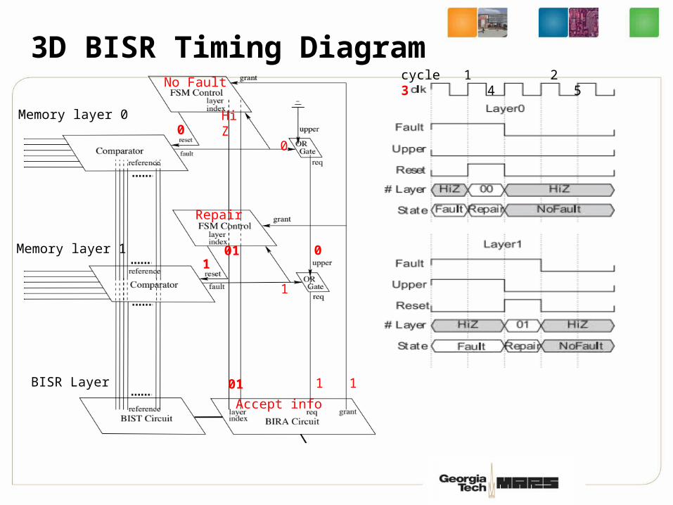
3D BISR Timing Diagram
Memory layer 0
Memory layer 1
0
1
1
1
HiZ
HiZ
cycle 1 2 3 4 5
0
0
Faulty
Faulty
Waiting
BISR Layer

Memory layer 0
Memory layer 1
1
1
1
1
00
HiZ
cycle 1 2 3 4 5
1
0
Repair
Faulty
00Accept info
BISR Layer
3D BISR Timing Diagram
0
1
Memory layer 0
Memory layer 1
1
1
0
1
HiZ
01
cycle 1 2 3 4 5
0
1
No Fault
Repair
01Accept info
BISR Layer
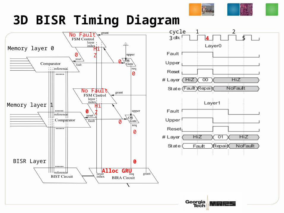
3D BISR Timing Diagram
0
Memory layer 0
Memory layer 1
0
0
0
0
0
HiZ
HiZ
cycle 1 2 3 4 5
0
0
No Fault
No Fault
Alloc GRU
BISR Layer
3D BISR Timing Diagram

12
We now have Parallel Testing
but still ….
Serial Layer-by-Layer Reporting

3D Redundant Cylinder for Repair
• Add redundant cylinder in BISR layer• Row, column, and cylinder replacement• Uncommon to have > 1 fault on a
cylinder
Memory layer 0
Memory layer 1
0
1
1
1
1
1
HiZ
HiZ
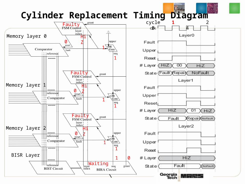
cycle 1 2 3 4
0
0
Faulty
Faulty
Waiting
Memory layer 2
BISR Layer
11
HiZ0
Faulty
Cylinder Replacement Timing Diagram

Cylinder Replacement Timing Diagram
Memory layer 0
Memory layer 1
0
1
1
1
1
1
00
HiZ
cycle 1 2 3 4
1
0
Repair
Faulty
Accept info
Memory layer 2
BISR Layer
11
HiZ0
Faulty
00
Memory layer 0
Memory layer 1
0
1
0
0
1
1
HiZ
01
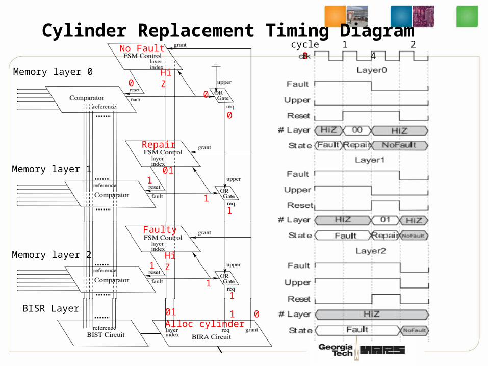
cycle 1 2 3 4
0
1
No Fault
Repair
Alloc cylinder
Memory layer 2
BISR Layer
11
HiZ1
Faulty
01
Cylinder Replacement Timing Diagram
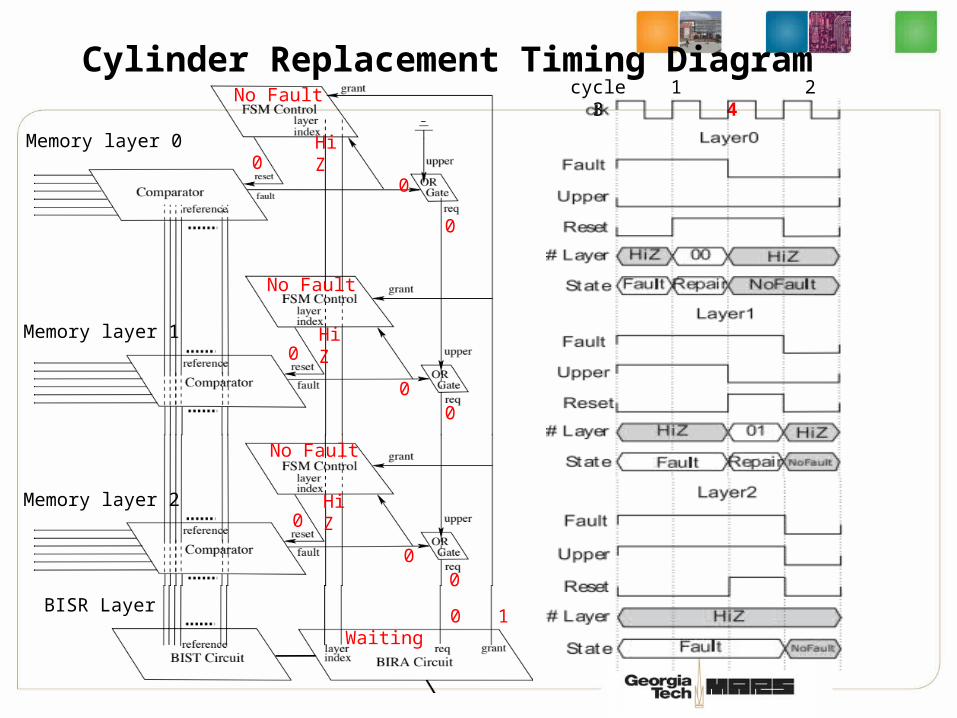
Memory layer 0
Memory layer 1
1
0
0
0
0
0
HiZ
HiZ
cycle 1 2 3 4
0
0
No Fault
No Fault
Waiting
Memory layer 2
BISR Layer
00
HiZ0
No Fault
Cylinder Replacement Timing Diagram

• 8-layer 3D memory• 1024×1024×8-bit per layer• Clustered fault model [Stapper, TCAD‘89]
• Assume certain susceptibility parameters of fabrication process [Lu et al., TVLSI’10]
• 23.5 faults per layer
Evaluation Baseline

Local vs. Global Redundancy
• Local: dedicated, non-shareable redundancy to each layer• Semi-global: Shareable within a 4-layer group, non-shareable
across groups• Global: Shareable redundancy across all memory layers• 27% higher repair rate over Local, 8.6% over Semi-Global.

3D BISR Comparison: GESP vs. MESP
• Grid: The width (x 8bits) of a row/column that a GRU can replace• 8.3% improvement (up to 27.6%)
Grid=4 Grid=8 Grid=16 Grid=32
Grid=64 Grid=128 Grid=256 Grid=512

Global Redundancy Sharing for 3D Memory
Parallelized BISR Procedure
New 3D Cylinder Repairing Structure
27% Higher Repair Rate over Local Scheme
8.3% Higher Repair Rate over MESP
Conclusion

That’s all, Folks !
Georgia TechECE MARS Labhttp://arch.ece.gatech.edu